WO2015045708A1 - 空調室外ユニット - Google Patents
空調室外ユニット Download PDFInfo
- Publication number
- WO2015045708A1 WO2015045708A1 PCT/JP2014/072259 JP2014072259W WO2015045708A1 WO 2015045708 A1 WO2015045708 A1 WO 2015045708A1 JP 2014072259 W JP2014072259 W JP 2014072259W WO 2015045708 A1 WO2015045708 A1 WO 2015045708A1
- Authority
- WO
- WIPO (PCT)
- Prior art keywords
- air
- rotor
- unit
- heat exchanger
- disposed
- Prior art date
- Legal status (The legal status is an assumption and is not a legal conclusion. Google has not performed a legal analysis and makes no representation as to the accuracy of the status listed.)
- Ceased
Links
Images




Classifications
-
- F—MECHANICAL ENGINEERING; LIGHTING; HEATING; WEAPONS; BLASTING
- F24—HEATING; RANGES; VENTILATING
- F24F—AIR-CONDITIONING; AIR-HUMIDIFICATION; VENTILATION; USE OF AIR CURRENTS FOR SCREENING
- F24F1/00—Room units for air-conditioning, e.g. separate or self-contained units or units receiving primary air from a central station
- F24F1/06—Separate outdoor units, e.g. outdoor unit to be linked to a separate room comprising a compressor and a heat exchanger
- F24F1/46—Component arrangements in separate outdoor units
-
- F—MECHANICAL ENGINEERING; LIGHTING; HEATING; WEAPONS; BLASTING
- F24—HEATING; RANGES; VENTILATING
- F24F—AIR-CONDITIONING; AIR-HUMIDIFICATION; VENTILATION; USE OF AIR CURRENTS FOR SCREENING
- F24F3/00—Air-conditioning systems in which conditioned primary air is supplied from one or more central stations to distributing units in the rooms or spaces where it may receive secondary treatment; Apparatus specially designed for such systems
- F24F3/12—Air-conditioning systems in which conditioned primary air is supplied from one or more central stations to distributing units in the rooms or spaces where it may receive secondary treatment; Apparatus specially designed for such systems characterised by the treatment of the air otherwise than by heating and cooling
- F24F3/14—Air-conditioning systems in which conditioned primary air is supplied from one or more central stations to distributing units in the rooms or spaces where it may receive secondary treatment; Apparatus specially designed for such systems characterised by the treatment of the air otherwise than by heating and cooling by humidification; by dehumidification
- F24F3/1411—Air-conditioning systems in which conditioned primary air is supplied from one or more central stations to distributing units in the rooms or spaces where it may receive secondary treatment; Apparatus specially designed for such systems characterised by the treatment of the air otherwise than by heating and cooling by humidification; by dehumidification by absorbing or adsorbing water, e.g. using an hygroscopic desiccant
- F24F3/1423—Air-conditioning systems in which conditioned primary air is supplied from one or more central stations to distributing units in the rooms or spaces where it may receive secondary treatment; Apparatus specially designed for such systems characterised by the treatment of the air otherwise than by heating and cooling by humidification; by dehumidification by absorbing or adsorbing water, e.g. using an hygroscopic desiccant with a moving bed of solid desiccants, e.g. a rotary wheel supporting solid desiccants
-
- F—MECHANICAL ENGINEERING; LIGHTING; HEATING; WEAPONS; BLASTING
- F24—HEATING; RANGES; VENTILATING
- F24F—AIR-CONDITIONING; AIR-HUMIDIFICATION; VENTILATION; USE OF AIR CURRENTS FOR SCREENING
- F24F3/00—Air-conditioning systems in which conditioned primary air is supplied from one or more central stations to distributing units in the rooms or spaces where it may receive secondary treatment; Apparatus specially designed for such systems
- F24F3/12—Air-conditioning systems in which conditioned primary air is supplied from one or more central stations to distributing units in the rooms or spaces where it may receive secondary treatment; Apparatus specially designed for such systems characterised by the treatment of the air otherwise than by heating and cooling
- F24F3/14—Air-conditioning systems in which conditioned primary air is supplied from one or more central stations to distributing units in the rooms or spaces where it may receive secondary treatment; Apparatus specially designed for such systems characterised by the treatment of the air otherwise than by heating and cooling by humidification; by dehumidification
- F24F3/147—Air-conditioning systems in which conditioned primary air is supplied from one or more central stations to distributing units in the rooms or spaces where it may receive secondary treatment; Apparatus specially designed for such systems characterised by the treatment of the air otherwise than by heating and cooling by humidification; by dehumidification with both heat and humidity transfer between supplied and exhausted air
-
- F—MECHANICAL ENGINEERING; LIGHTING; HEATING; WEAPONS; BLASTING
- F24—HEATING; RANGES; VENTILATING
- F24F—AIR-CONDITIONING; AIR-HUMIDIFICATION; VENTILATION; USE OF AIR CURRENTS FOR SCREENING
- F24F6/00—Air-humidification, e.g. cooling by humidification
- F24F6/02—Air-humidification, e.g. cooling by humidification by evaporation of water in the air
- F24F6/06—Air-humidification, e.g. cooling by humidification by evaporation of water in the air using moving unheated wet elements
Definitions
- the present invention relates to a unit outside an air conditioning room including a humidification unit.
- an air-conditioning outdoor unit equipped with a humidifying unit for humidifying the room separately from the outdoor unit on the outdoor unit that stores the compressor, the outdoor heat exchanger, the outdoor fan, and the like.
- a humidifying unit for humidifying the room separately from the outdoor unit on the outdoor unit that stores the compressor, the outdoor heat exchanger, the outdoor fan, and the like.
- the product size of the outdoor unit is increased because the humidification unit is mounted on the outdoor unit, so that the height of the outdoor unit increases.
- each component provided in the humidifying unit is moved to the upper part of the outdoor unit and incorporated in the outdoor unit.
- a unit outside the air conditioning room that has a humidification function and a reduced product size is realized.
- the inside of the air-conditioning outdoor unit is divided into a machine room in which a compressor or the like is arranged and a blower room in which an outdoor heat exchanger, an outdoor fan or the like is arranged.
- the rotor that is one of the components of the humidifying unit and adsorbs moisture from the outside air and releases the adsorbed moisture is disposed along the horizontal plane. Yes.
- the entire rotor is located in the blower chamber and is disposed in front of the outdoor heat exchanger.
- a part of the outdoor heat exchanger may be blocked by the humidification unit. If it does so, since it becomes difficult for external air to pass through the part blocked
- an object of the present invention is to provide an air-conditioning outdoor unit that can prevent the performance deterioration of the outdoor heat exchanger.
- the air-conditioning outdoor unit includes a casing, a compressor, an outdoor heat exchanger, an outdoor fan, and a humidification unit.
- the casing is divided into a blower room and a machine room that are lined up side by side.
- the compressor is disposed in the machine room.
- the outdoor heat exchanger is disposed in the blower room.
- the outdoor fan is disposed in the blower room.
- the outdoor fan passes outside air through the outdoor heat exchanger.
- the humidifying unit has a plate-like rotor.
- the rotor includes a moisture absorption region and a moisture release region.
- the hygroscopic region is a region that adsorbs moisture in the outside air.
- the moisture release area is an area for releasing moisture adsorbed on the moisture absorption area when heated.
- the rotor is disposed forward of the outdoor heat exchanger along the vertical plane. The rotor is arranged so that the moisture absorption area is located in the blower room and the moisture release area is located in the machine room. And the whole rotor drive motor which rotationally drives a rotor is arrange
- the rotor is disposed along the vertical plane, the moisture absorption area is located in the blower room, and the moisture release area is located in the machine room. For this reason, it is possible to increase the distance between the outdoor heat exchanger and the rotor as compared with the configuration in which the rotor is arranged along the horizontal plane, and the performance associated with the difficulty in flowing outside air to the outdoor heat exchanger. A decrease can be prevented.
- the portion of the rotor drive motor that rotationally drives the rotor is disposed across the blower chamber and the machine chamber, the portion of the rotor drive motor that is located on the blower chamber side is an outside generated by driving the outdoor fan.
- the part located on the machine room side is exposed to exhaust heat generated by driving a compressor or the like.
- the portion located on the blower chamber side is cooled and the portion located on the compressor chamber side is heated, so that the rotor drive motor is likely to be abnormal.
- the durability of the rotor drive motor is increased. It becomes difficult to secure sex.
- the entire rotor drive motor is disposed in the machine room. For this reason, it is possible to prevent an abnormality of the rotor drive motor resulting from the cooling of a part of the blower fan. Thereby, the durability of the rotor drive motor can be ensured.
- the air conditioning room outside unit is the air conditioning room outside unit according to the first aspect, and includes an electrical component box.
- the electrical component box stores electrical components for controlling devices including the compressor and the outdoor fan. And the electrical component box is arrange
- the electrical component box is arranged so that at least a part of the electrical component box overlaps the rotor when viewed from the front. For this reason, for example, the dimension of the left-right direction of a casing can be made smaller than arrange
- the air conditioner outside unit according to the third aspect of the present invention is the air conditioner outside unit according to the second aspect, in which the electrical component box is disposed along the vertical plane.
- the electrical component box and the rotor are arranged so as to be lined up in the front-rear direction.
- the rotor and the electrical component box are arranged along the vertical plane, and the electrical component box and the rotor are arranged so that they are arranged in the front and back.
- the width dimension in the front-rear direction of the casing can be made smaller than the case where the electrical component box is disposed so as to extend along.
- the electrical component box is arranged along the vertical plane because the electrical component box is not inclined at all with respect to the vertical plane, and the electrical component box is ⁇ 15 ° with respect to the vertical plane. It includes even those that are tilted.
- the air-conditioning outdoor unit according to the fourth aspect of the present invention is the air-conditioning outdoor unit according to the second or third aspect, wherein the machine room is formed so that the width in the left-right direction becomes wider toward the front. And the electrical component box is arrange
- the air-conditioning outdoor unit according to the fifth aspect of the present invention is the air-conditioning outdoor unit according to any of the first to fourth aspects, wherein the rotor has an upper end near the upper end of the outdoor heat exchanger or an outdoor heat exchanger. It arrange
- the air-conditioning outdoor unit is the air-conditioning outdoor unit according to any one of the first to fifth aspects, and the humidification unit has a heater.
- the heater is for heating the moisture release region.
- the heater is disposed in the machine room. In this outdoor unit, the heater and the rotor drive motor are arranged in the machine room, so that the wiring operation can be simplified. Thereby, assembly property and maintainability can be improved.
- the air-conditioning outdoor unit according to the seventh aspect of the present invention is the air-conditioning outdoor unit according to any one of the first to sixth aspects, and there is a gap between the outdoor heat exchanger and the rotor. For this reason, in this air conditioning outdoor unit, the rotor can be prevented from contacting the outdoor heat exchanger, and the rotor can be prevented from being damaged.
- the air conditioning outdoor unit includes a casing, a compressor, an outdoor heat exchanger, an outdoor fan, a humidification unit, and an electrical component box.
- the casing is divided into a blower room and a machine room that are lined up side by side.
- the compressor is disposed in the machine room.
- the outdoor heat exchanger is disposed in the blower room.
- the outdoor fan is disposed in the blower room.
- the outdoor fan passes outside air through the outdoor heat exchanger.
- the humidifying unit has a plate-like rotor.
- the rotor includes a moisture absorption region and a moisture release region.
- the hygroscopic region is a region that adsorbs moisture in the outside air.
- the moisture release area is an area for releasing moisture adsorbed on the moisture absorption area when heated.
- the rotor is disposed forward of the outdoor heat exchanger along the vertical plane.
- the electrical component box stores electrical components for controlling devices including the compressor and the outdoor fan.
- the rotor is arranged so that the moisture absorption area is located in the blower room and the moisture release area is located in the machine room.
- the electrical component box is arrange
- an air conditioning outdoor unit that includes an outdoor unit that stores a compressor, an outdoor heat exchanger, an outdoor fan, and the like, and a humidifying unit that has a rotor that adsorbs moisture from the outside air and releases the adsorbed moisture.
- the electrical component box which accommodates the electrical components for controlling a compressor, an outdoor fan, etc. is arrange
- the lateral dimension of the casing needs to be larger than the lateral dimension of the rotor and electrical component box. Become.
- the dimensions of the equipment to be accommodated must be taken into account.
- the product size of the unit outside the air-conditioning room increases as the dimensions of the casing increase.
- the air-conditioning outdoor unit is arranged so that at least a part of the electrical component box overlaps the rotor when viewed from the front. For this reason, the dimension of the left-right direction of a casing can be made small, for example rather than arrange
- the width dimension in the front-rear direction of the casing is the rotor or the electrical component box. It is necessary to design in consideration of the width dimension in the front-rear direction.
- the electrical component box is arranged along the vertical plane, and the electrical component box and the rotor are arranged so as to be lined up and down, for example, the longitudinal direction thereof
- the width dimension in the front-rear direction of the casing can be made smaller than that in which the electrical component box is disposed so as to extend along the horizontal plane.
- the electrical component box is arranged along the vertical plane because the electrical component box is not inclined at all with respect to the vertical plane, and the electrical component box is ⁇ 15 ° with respect to the vertical plane. It includes even those that are tilted.
- the machine room is formed so that the width in the left-right direction becomes wider toward the front, and the electrical component box is disposed in the front inside the machine room, Since the electrical component box is arranged in the front of the machine room, which is wider in the left-right direction than the interior rear of the machine room, the electrical component box can be moved in the left-right direction rather than disposed in the machine room.
- the dimensions can be increased.
- the humidifying unit has a heater for heating the moisture release region, and the rotor is rotationally driven by the rotor drive motor, so that not only the electrical component box but also the heater and the rotor drive motor If it is arranged in the machine room, the wiring operation can be simplified. Thereby, assembly property and maintainability can be improved.
- the air conditioning outdoor unit according to the first aspect of the present invention can prevent the performance of the outdoor heat exchanger from being degraded.
- the degree of freedom in designing the electrical component box can be improved.
- the assemblability and the maintainability can be improved.
- the rotor can be prevented from being damaged.
- the schematic refrigerant circuit figure of an air conditioning apparatus provided with the unit outside an air-conditioning room which concerns on one Embodiment of this invention.
- FIG. 1 The figure for demonstrating arrangement
- an air conditioner 10 including an air conditioning outdoor unit 30 includes an air conditioning indoor unit 20 in addition to the air conditioning outdoor unit 30.
- the indoor unit 20 and the air-conditioning outdoor unit 30 are configured to be connected by a communication pipe 12.
- the air conditioner 10 has a plurality of operation modes such as a cooling operation, a heating operation, a dehumidifying operation, a humidifying operation, and a ventilation operation, and these operation modes can be appropriately combined.
- the air conditioner 10 In order to cool or warm the indoor air, heat exchange is performed in the air conditioning indoor unit 20 and the air conditioning outdoor unit 30, and the air conditioning indoor unit 20 and the air conditioning outdoor unit 30 are connected through the communication pipe 12. There is heat transfer between.
- the air conditioner 10 has a refrigerant circuit as shown in FIG. A compressor 31, a four-way switching valve 32, an outdoor heat exchanger 33, an electric valve 34, and an indoor heat exchanger 21 are mainly connected to the refrigerant circuit.
- the indoor heat exchanger 21 is provided in the air conditioning indoor unit 20, and the compressor 31, the four-way switching valve 32, the outdoor heat exchanger 33, and the electric valve 34 are provided in the air conditioning outdoor unit 30.
- a liquid refrigerant pipe 14 and a gas refrigerant pipe 16 that substantially connect the air conditioning indoor unit 20 and the air conditioning outdoor unit 30 pass.
- the air-conditioning room outdoor unit 30 includes a humidification unit 60 having a function of taking moisture from outside air.
- the four-way switching valve 32 is connected to the solid line state shown in FIG. 1, and the refrigerant compressed and discharged by the compressor 31 is sent to the outdoor heat exchanger 33 via the four-way switching valve 32. .
- the refrigerant that has been deprived of heat by exchanging heat with the outside air in the outdoor heat exchanger 33 is sent to the motor-operated valve 34.
- the high-pressure liquid refrigerant is changed to a low-pressure state by the motor-operated valve 34.
- the refrigerant expanded by the electric valve 34 enters the indoor heat exchanger 21 through the filter 35 through the liquid closing valve 37 and the liquid refrigerant pipe 14.
- the refrigerant whose temperature has risen due to heat exchange with room air in the indoor heat exchanger 21 is sent to the four-way switching valve 32 through the gas refrigerant pipe 16 and the gas closing valve 38. Since the four-way switching valve 32 is in a state in which the gas closing valve 38 and the accumulator 36 are connected, the refrigerant sent from the indoor heat exchanger 21 through the gas refrigerant pipe 16 passes through the accumulator 36 to the compressor. 31 and is sucked into the compressor 31.
- the four-way switching valve 32 is connected to the broken line state shown in FIG. 1, and the refrigerant compressed and discharged by the compressor 31 is sent to the indoor heat exchanger 21. Then, the refrigerant exiting the outdoor heat exchanger 33 returns to the compressor 31 along a path opposite to that during cooling. That is, during heating, the compressor 31, the four-way switching valve 32, the gas refrigerant pipe 16, the indoor heat exchanger 21, the liquid refrigerant pipe 14, the electric valve 34, the outdoor heat exchanger 33, the four-way switching valve 32, the accumulator 36, and The refrigerant circulates in the order of the compressor 31.
- the air-conditioned indoor unit 20 includes an indoor fan 22 driven by a motor as shown in FIG. It is provided on the downstream side of the exchanger 21.
- the indoor fan 22 for example, a cross flow fan is employed.
- the indoor fan 22 is driven, the indoor air sucked from the air inlet 23 at the upper part of the air-conditioned indoor unit 20 passes through the indoor heat exchanger 21 and is blown out from the air outlet 24 at the lower part of the air-conditioned indoor unit 20.
- an air supply port 25 of the air supply duct 18 is provided in the upstream space of the indoor heat exchanger 21.
- the air supply duct 18 is connected to the humidification unit 60, and air sent from the humidification unit 60 is supplied from the air supply port 25 to the upstream space of the indoor heat exchanger 21.
- the blower outlet of the air-conditioning indoor unit 20 is driven by driving the indoor fan 22 with the air being supplied from the air supply port 25.
- the humidity of the conditioned air blown from 24 can be increased.
- the air conditioning indoor unit 20 can perform the humidification operation and the heating operation simultaneously.
- the air conditioning room outside unit 30 includes a casing 40. As shown in FIG. 1, the inside of the casing 40 is divided into a blower chamber S ⁇ b> 1 and a machine chamber S ⁇ b> 2 by a partition plate 43. In the unit 30 outside the air conditioning room, the blower room S1 and the machine room S2 are shielded by the partition plate 43 so that the wind does not enter the machine room S2 from the blower room S1.
- an outdoor fan 39 is disposed in front of the outdoor heat exchanger 33 in addition to the above-described devices constituting the refrigerant circuit and the humidification unit 60.
- the outdoor fan 39 and the outdoor heat exchanger 33 are disposed in the blower chamber S1, and the compressor 31, the four-way switching valve 32, the electric valve 34, and the accumulator 36 are disposed in the machine chamber S2. Has been placed.
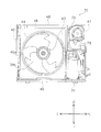
- FIG. 2 is a front view of the air conditioning room outside unit 30, and shows a state where the electrical component box 50, the grill and the front plate 46 are partly removed from the air conditioning room outside unit 30.
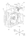
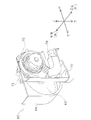
- FIG. 3 is a perspective view of the air conditioning room outside unit 30, and a part of the front plate 46 removed in FIG. 2 in the air conditioning room outside unit 30 from which the main body 51, the grille, and the top plate 48 of the electrical component box 50 are removed. Is a virtual plane.
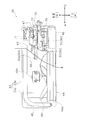
- FIG. 4 is a plan view of the unit 30 outside the air conditioning room, and shows a state where the top plate 48 of the unit 30 outside the air conditioning room is removed. In addition, the arrow of FIG. 4 has shown the flow of the air which passes along the moisture absorption area
- FIG. 4 has shown the flow of the air which passes along the moisture absorption area
- the casing 40 of the air conditioning outdoor unit 30 includes a front plate 46, a left side plate 45, a right side plate 47, a top plate 48, and a bottom plate 49, as shown in FIGS.
- a circular air outlet 44 is formed in the front plate 46, and a ring-shaped bell mouth 46 a is attached around the air outlet 44.
- the front side of the air outlet 44 is covered with a grill (not shown) so that a propeller 39b of an outdoor fan 39, which will be described later, does not come into contact with an object outside the air conditioning outdoor unit 30.
- the grill is attached to the front plate 46 of the casing 40.
- the left side plate 45 is formed in a lattice shape, and can guide outside air to the outdoor heat exchanger 33 from the left side.
- the right side plate 47 constitutes a part of the rear surface from the right end of the second portion 33b of the outdoor heat exchanger 33 to be described later to the right side surface and the entire right side surface.
- a protective wire mesh that covers the second portion 33b of the outdoor heat exchanger 33 is attached to the rear side of the blower chamber S1.
- the protective wire mesh is formed with an opening for introducing outside air to the second portion 33b of the outdoor heat exchanger 33.
- the right side plate 47 is formed with a suction port 72 serving as an inlet of a moisture release path described later.
- the partition plate 43 extends forward from the right end of the outdoor heat exchanger 33 and extends upward from the bottom plate 49. For this reason, it can be said that the inside of the casing 40 is divided into the blower chamber S1 and the machine chamber S2 arranged side by side with the partition plate 43 as a boundary. Further, the partition plate 43 is disposed obliquely with respect to the front-rear direction so that the width in the left-right direction of the machine room S2 increases toward the front (see FIG. 4). In the present embodiment, the partition plate 43 is curved. The rear portion of the partition plate 43 extends from the bottom plate 49 to the top plate 48.
- the electrical component box 50 includes a main body 51 and a heat sink 52.
- the main body 51 may be made of a metal such as aluminum, or may be made of an elastic resin.
- the resin material for example, HIPS (High-Impact-Polystyrene) and ABS (Acrylonitrile-Butadiene-Styrene) are used.
- the main body 51 is a box-shaped member that opens forward, and is arranged so that the opening is positioned forward in the front view of the air-conditioning room outside unit 30. That is, it can be said that the main body 51 is disposed in front of the machine room S2.
- the main body 51 is mounted with a control board (not shown) in which electronic components for driving various devices included in the air conditioning outdoor unit 30 are integrated.
- the control board is disposed such that the surface on which the electronic components and the like are disposed faces the opening of the main body 51.
- the front board 46 is arrange
- the main body 51 is disposed along a vertical plane. Note that the main body 51 is arranged along the vertical plane here, because the main body 51 is not inclined at all with respect to the vertical plane, and the main body 51 is inclined about ⁇ 15 ° with respect to the vertical plane. Up to what is arranged.
- the main body 51 of this embodiment is not inclined at all with respect to the vertical plane. For this reason, the main body 51 has a vertical arrangement in which the width direction (thickness direction) extends in the front-rear direction so as not to take a place in the front-rear direction.
- the heat sink 52 is a fin for escaping the heat generated by the electrical components stored in the main body 51 to the outside, and is disposed so as to protrude from the opening 43a into the blower chamber S1. In the present embodiment, the entire heat sink 52 is disposed on the blower chamber S1 side, but a part of the heat sink 52 may be disposed on the machine chamber S2 side.
- the front end of the partition plate 43 is attached in contact with the front
- the outdoor heat exchanger 33 has an L shape when viewed from above, and constitutes a first portion 33 a facing the left side plate 45 of the casing 40 and the back surface of the casing 40. And a second portion 33b facing the protective wire mesh.
- the outdoor heat exchanger 33 has a height that reaches the top plate 48 from the bottom plate 49. And the outdoor heat exchanger 33 has many fins extended long in a height direction, and the heat exchanger tube penetrated through the fins and attached horizontally.
- the heat transfer tubes are arranged in multiple rows in the height direction by being bent back and forth at both ends of the outdoor heat exchanger 33.
- Outdoor fan 39 is a fan that blows outside air sucked from the rear side (rear side) of the outdoor heat exchanger 33 through the outdoor heat exchanger 33 to the front side (front side) of the air-conditioning outdoor unit 30.
- the outdoor fan 39 includes a fan motor 39a and a propeller 39b driven by the fan motor 39a.
- the propeller 39b is arranged so that a part of the propeller 39b enters the space surrounded by the bell mouth 46a.
- the fan motor 39a is attached to the back side of the propeller 39b, and the rotation shaft of the propeller 39b and the drive shaft of the fan motor 39a are coupled.
- the fan motor 39a is supported by a fan motor base (not shown).
- the fan motor base is attached to a fixed plate (not shown) fixed to the bottom plate 49 and the upper end 33t of the outdoor heat exchanger 33.
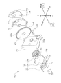
- FIG. 5 is an exploded view of the humidifying unit 60.
- the humidification unit 60 has a moisture absorption path and a moisture release path, and is arranged such that the moisture absorption path is located in the blower room S1 of the air conditioning room outside unit 30, and the moisture drying path is located in the machine room S2 of the air conditioning room outside unit 30. Has been.
- the upper end position of the humidifying unit 60 is arranged in the vicinity of the upper end (top) 33 t of the outdoor heat exchanger 33 or lower than the upper end 33 t of the outdoor heat exchanger 33. Yes.
- the upper end of the humidifying unit 60 is the upper end of the frame 70, and the height of the upper end of the frame 70 coincides with the height of the upper end 33t of the outdoor heat exchanger 33.
- the humidification unit 60 mainly includes a humidification rotor 63, a heater 71, and a turbo fan 75.
- a part of the humidification rotor 63 is arranged in the moisture absorption path, and the other part of the humidification rotor 63, the heater 71 and the turbo fan 75 are arranged in the moisture release path.
- the humidification rotor 63, the heater 71 and the turbo fan 75 are fixed to the frame 70. More specifically, the heater 71 and the humidifying rotor 63 are fixed to a support plate 73, and the support plate 73 is attached to the back side of the frame 70 (see FIG. 5).
- the turbo fan 75 is attached to the front side of the frame 70 opposite to the surface to which the support plate 73 is attached (see FIG. 5).
- the humidification rotor 63 is a single plate-like moisture absorbing / releasing material.
- the shape of the humidification rotor 63 may be any shape as long as it is a plate shape.
- the humidification rotor 63 has a disk shape.
- the single plate-like moisture absorbing / releasing material referred to here includes a single plate-like moisture absorbing / releasing material constituting the humidifying rotor 63 and a plurality of moisture absorbing / releasing materials having the same shape or different shapes. A combination that forms one plate-like humidification rotor 63 is also included.
- the humidification rotor 63 is a zeolite rotor having a honeycomb structure formed by firing of zeolite or the like.
- the humidification rotor 63 is mounted so as to rotate about the center of the disk as a rotation axis, and is rotationally driven by the power of the rotor drive motor 65 transmitted to the gear 64 provided around the humidification rotor 63.
- the entire rotor drive motor 65 is disposed in the machine room S2. Furthermore, in the present embodiment, the rotor drive motor 65 is disposed on the radially outer side from the outer periphery of the humidification rotor 63 so as not to overlap the humidification rotor 63 in a front view.
- the adsorbent such as zeolite forming the humidifying rotor 63 has a property of absorbing moisture from air at room temperature and releasing the moisture when the air is heated to a high temperature by a heater 71 or the like and becomes higher than room temperature. ing. That is, a region of the humidifying rotor 63 that is not exposed to high-temperature air becomes a moisture-absorbing region 63a that adsorbs moisture from the outside air, and a region that is exposed to high-temperature air releases moisture adsorbed. 63b.
- the humidification rotor 63 is arranged so that the rotation axis extends in the front-rear direction. That is, the humidification rotor 63 is disposed along the vertical plane. Note that the humidification rotor 63 is disposed along the vertical plane here because the humidification rotor 63 is not inclined at all with respect to the vertical plane, so that the humidification rotor 63 is ⁇ 15 with respect to the vertical plane. It includes even those arranged at an angle of about °. And the humidification rotor 63 of this embodiment shall not be inclined at all with respect to the vertical plane. For this reason, the humidification rotor 63 is arranged vertically so that the width direction (thickness direction) extends in the front-rear direction so as not to take up space in the front-rear direction.
- the moisture absorption area 63 a of the humidification rotor 63 is located in the blower room S ⁇ b> 1 of the unit 30 outside the air conditioning room, and the moisture release area 63 b of the humidification rotor 63 is located in the machine room S ⁇ b> 2 of the unit 30 outside the air conditioning room.
- the humidification rotor 63 is disposed in the opening 43 a of the partition plate 43.
- region 63a of the humidification rotor 63 of this embodiment is arrange
- the outdoor heat exchanger 33 is disposed with a gap so as to face the second portion 33b of the outdoor heat exchanger 33. For this reason, the moisture absorption area
- the upper end 63t of the humidification rotor 63 of the present embodiment is at a position lower than the upper end 33t of the outdoor heat exchanger 33.
- the relationship of the height position of the humidification rotor 63 and the outdoor heat exchanger 33 is not limited to this.
- the height position of the upper end 63 t of the humidification rotor 63 may be at a height position near the upper end 33 t of the outdoor heat exchanger 33.
- the height of the upper end 63t of the humidifying rotor 63 may coincide with the height of the upper end 33t of the outdoor heat exchanger 33, and is slightly higher than the upper end 33t of the outdoor heat exchanger 33 (for example, The position may be 10% higher than the height of the outdoor heat exchanger 33).
- the humidification rotor 63 is disposed so as to overlap at least a part of the electrical component box 50 disposed along the vertical plane in a front view (see FIG. 3).
- the vertical surface of the electrical component box 50 and the vertical surfaces of the moisture release area 63b and the reheat area 63c of the humidification rotor 63 are located facing each other when viewed from the front.
- the humidification rotor 63 and the electrical component box 50 are arrange
- the heater 71 is provided on the side of the moisture release area 63 b of the humidification rotor 63.
- the heater 71 has a structure in which a heating wire (not shown) is provided in a cylindrical casing, and heats the outside air sucked from the suction port 72 and sent to the humidification rotor 63 with a heating wire.
- a heating wire not shown
- the humidification rotor 63 when the heated air passes through the honeycomb structure opening of the humidification rotor 63, the air sucked into the turbofan 75 is humidified by being dehumidified from the humidification rotor 63.
- the heater 71 is attached to a heater support member 74 as shown in FIG.
- the heater support member 74 has a semicircular base portion 74a and an outer wall portion 74b erected from the peripheral edge portion of the base portion 74a, and the side (the humidifying rotor 63 side) is released.
- the heater 71 is attached to the base portion 74 a so as to be covered with the heater support member 74.
- the heater support member 74 constitutes a part of the moisture release path. Note that the casing of the heater 71 and the heater support member 74 are formed of sheet metal because heat resistance is required.
- the heater 71 is installed in the machine room S ⁇ b> 2 of the unit 30 outside the air-conditioning room, and is disposed on the side opposite to the electrical component box 50 with the humidification rotor 63 interposed therebetween.
- the vertical surface of the electrical component box 50 and the vertical surface of the heater support member 74 overlap each other at about 50% when viewed from the front.
- 80% or more of the vertical surface of the heater support member 74 may overlap the vertical surface of the electrical component box 50 in a front view.
- the turbo fan 75 generates an air flow from the air conditioned outdoor unit 30 toward the air conditioned indoor unit 20.
- the turbo fan 75 is disposed so as to face the heater 71 with the humidification rotor 63 interposed therebetween.
- the electrical component box 50 is disposed on the opposite side of the heater 71 with the turbo fan 75 and the humidification rotor 63 interposed therebetween. Furthermore, the turbo fan 75 is installed in the machine room S2 as shown in FIG. 2 and FIG.
- the turbo fan 75 has a fan motor 75a, an impeller 75b driven by the fan motor 75a, and a fan casing 75c that houses the impeller 75b, and air sucked from the rotation axis direction of the impeller 75b. Is blown out radially outward.
- the rotation shaft of the impeller 75b is arranged to extend in the front-rear direction.
- the turbo fan 75 has a vertically arranged arrangement that does not take up space in the front-rear direction.
- the suction portion 76 of the turbo fan 75 opens rearward. Further, the discharge part 77 of the turbo fan 75 opens downward.
- a humidification duct 78 is connected to the discharge unit 77, and the air supply duct 18 is attached to the humidification duct 78. For this reason, the air sucked from the suction portion 76 of the turbo fan 75 is guided to the air supply duct 18 via the humidification duct 78 and blown out from the air outlet 24 of the air conditioning indoor unit 20 via the air supply duct 18. become.
- FIG. 6 is a diagram for explaining the air flow in the humidification rotor 63.
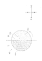
- FIG. 7 is a diagram for explaining the moisture release region 63b, the moisture absorption region 63a, and the reheat region 63c of the humidification rotor 63.
- region 63c are each shown.
- the flow of air during the humidifying operation will be described.
- the humidification operation is performed in combination with the heating operation. For this reason, during the humidifying operation, the compressor 31 and the outdoor fan 39 are driven.
- the humidifying rotor 63 is rotated at a predetermined rotational speed by the power of the rotor drive motor 65, and the heater 71 and the turbo fan 75 are driven. Since the humidification rotor 63 rotates, the moisture adsorbed by the humidification rotor 63 due to moisture absorption in the moisture absorption area 63a is carried to the moisture release area 63b as the humidification rotor 63 rotates, and the moisture release in the moisture release area 63b. The moisture adsorbed by the air is desorbed, so that the air around the moisture release region 63b is humidified.
- the humidification rotor 63 of the present embodiment rotates counterclockwise when viewed from the front, and when the portion functioning as the moisture absorption region 63a rotates and comes to a position facing the heater support member 74, the moisture release region 63b. Function as.
- the turbo fan 75 since the turbo fan 75 is driven during the humidification operation, the air flow from the air-conditioning room outdoor unit 30 to the air-conditioning indoor unit 20, that is, the outside air sucked from the suction port 72 passes through the humidification rotor 63 and the heater 71. Thus, an air flow blown out to the air supply duct 18 is generated. More specifically, the outside air sucked from the suction port 72 first circulates in front of the humidification rotor 63 and reaches the heater 71 through the humidification rotor 63 from the front to the rear. The outside air reaching the heater 71 passes through the casing of the heater 71. At this time, the outside air is heated by the heater 71.
- the air that has passed through the housing of the heater 71 proceeds to the moisture release region 63b of the humidification rotor 63, and passes through the moisture release region 63b of the humidification rotor 63 from the rear toward the front. At this time, the moisture release area 63b of the humidification rotor 63 is exposed to the air whose temperature has been increased by the heater 71 to release moisture. Then, the air that has passed through the moisture release region 63 b of the humidification rotor 63 is sucked into the turbo fan 75 through the opening 70 a formed in the frame 70 and blown out to the air supply duct 18 through the humidification duct 78. . The air humidified by the humidification rotor 63 in this way is guided to the air conditioning indoor unit 20 through the air supply duct 18.
- the part located in fan chamber S1 among the humidification rotors 63 becomes the moisture absorption area
- the portion located on the downstream side of the air flow from the heater 71 becomes the moisture release region 63b, and the other portion becomes the reheat region 63c.
- the reheat region 63 c is a portion where the outside air sucked from the suction port 72 first passes through the humidification rotor 63.
- the function of the humidification rotor 63 is switched in the order of the moisture absorption region 63a, the moisture release region 63b, and the reheat region 63c. Since the reheat region 63c is a portion that was the moisture release region 63b until immediately before, the temperature is high. For this reason, the outside air sucked from the suction port 72 is heated by the heat of the reheat region 63c by passing through the reheat region 63c. Further, the reheat area 63c is cooled by the passage of outside air, and then becomes the moisture absorption area 63a by the rotation of the humidification rotor 63.
- the humidification rotor is disposed along the horizontal plane, and the entire humidification rotor is located in the blower chamber, so that a part of the outdoor heat exchanger is blocked by the humidification unit, In the outdoor heat exchanger, it is difficult for outside air to pass through the portion blocked by the humidifying unit, and the performance of the outdoor heat exchanger may be deteriorated.
- the humidification rotor 63 is disposed along the vertical plane. Further, the moisture absorption area 63 a of the humidification rotor 63 is located in the blower room S 1 of the air conditioning room outside unit 30, and the moisture release area 63 b of the humidification rotor 63 is located in the machine room S 2 of the air conditioning room outside unit 30. For this reason, compared with the case where the humidification rotor 63 is arrange
- the humidification rotor 63 is disposed along the vertical plane, the depth of the air-conditioning outdoor unit 30, that is, in the front-rear direction, rather than the humidification rotor 63 disposed along the horizontal plane. Since the dimensions can be shortened, the product size can be reduced.
- the upper end 63t of the humidification rotor 63 of the present embodiment is at a position lower than the upper end 33t of the outdoor heat exchanger 33. For this reason, compared with the case where the humidification rotor 63 is arrange
- the upper end 63t of the humidification rotor 63 is located at a position lower than the top plate 48, the outside air easily flows efficiently into the moisture absorption region 63a of the humidification rotor 63.
- the heater 71, the rotor drive motor 65, and the main body 51 of the electrical component box 50 are arranged in the machine room S ⁇ b> 2 of the air conditioning room outside unit 30.
- the electrical parts are collectively arranged in the machine room S2, thereby simplifying wiring work such as wiring.
- the assembly property and maintenance property (service property) of the air-conditioning outdoor unit 30 can be improved.
- the moisture release area 63b of the humidification rotor 63 is located in the machine room S2 of the air conditioning room outside unit 30, the waste heat of the compressor 31 and electrical components is used to be sucked from the suction port 72.
- the outside air can be heated.
- the heater 71 is disposed on the side opposite to the electrical component box 50 with the humidification rotor 63 interposed therebetween.
- the heater 71 is arranged on the opposite side of the electrical component box 50 with the humidification rotor 63 interposed therebetween, thereby separating the heater 71 and the electrical component box 50 of the humidification unit 60 as much as possible. be able to. For this reason, it becomes difficult for the heat from the heater 71 to be directly transmitted to the electrical component box 50, and the possibility that the electronic components and the control board in the main body 51 of the electrical component box 50 are deteriorated by heat can be reduced.
- the degree of freedom of the members constituting the electrical component box 50 is increased. That is, for example, when the electrical component box 50 is formed of a material such as a resin, it is necessary to select the material in consideration of heat resistance. However, in the present embodiment, heat from the heater 71 is not easily transmitted to the electrical component box 50. Therefore, the degree of freedom of material selection increases.
- the heater 71 and the electrical component box 50 are arranged on the same side with respect to the humidification rotor 63, it is necessary to secure a space to keep the electrical component box 50 away from the heater 71. Since the electric component box 50 can be separated from the heater 71 by disposing the heater 71 on the opposite side of the electric component box 50 with the 63 interposed therebetween, a separate for separating the electric component box 50 and the heater 71 from each other is provided. It is not necessary to secure the space, and the space in the air conditioning room outside unit 30 can be effectively used.
- the vertical surface of the electrical component box 50 and the vertical surface of the heater support member 74 overlap each other at about 50% when viewed from the front.
- 80% or more of the vertical surface of the heater support member 74 may overlap the vertical surface of the electrical component box 50 in a front view.
- the turbo fan 75 is disposed so as to face the heater 71 with the humidifying rotor 63 interposed therebetween, and the electrical component box 50 is disposed on the opposite side of the heater 71 with the turbo fan 75 and the humidifying rotor 63 interposed therebetween.
- the electrical component box 50 is disposed on the opposite side of the heater 71 with the turbo fan 75 and the humidification rotor 63 interposed therebetween, so that the heater 71 and the electrical component box 50 are further separated by the turbo fan 75. Can be made. Thereby, it can further suppress that the heat from the heater 71 is transmitted to the electrical component box 50.
- the rotor drive motor 65 is disposed in the machine room S2. For this reason, the rotor drive motor 65 is not cooled by the driving of the outdoor fan 39, and the abnormality of the rotor drive motor 65 due to this can be prevented. As a result, the durability of the rotor drive motor 65 can be ensured.
- the rotor drive motor is arranged in the blower chamber and is arranged between the humidification rotor and the outdoor fan, the outside air does not flow to the humidification rotor due to the ventilation resistance of the rotor drive motor, and the humidification rotor There is a possibility that the hygroscopic performance of the product may be lowered.
- the rotor drive motor 65 is disposed radially outside the outer periphery of the humidification rotor 63 so that the rotor drive motor 65 and the humidification rotor 63 do not overlap in front view. For this reason, the fall of the moisture absorption performance of the humidification rotor 63 resulting from the ventilation resistance of the rotor drive motor 65 can be prevented.
- At least a part of the electrical component box 50 is disposed so as to overlap the humidification rotor 63 in a front view.
- the dimension of the left-right direction of the casing 40 can be made small rather than arrange
- each of the humidification rotor 63 and the electrical component box 50 is disposed along a vertical plane. Further, the humidification rotor 63 and the electrical component box 50 are arranged so as to be arranged in the front-rear direction. For this reason, for example, when the electrical component box 50 is disposed such that the longitudinal direction thereof extends along the horizontal plane, that is, when the electrical component box 50 is disposed horizontally, the casing 40 is disposed in the front-rear direction. The width dimension can be reduced. Thereby, the thickness reduction of the air-conditioning outdoor unit 30 can be realized.
- the machine room S2 is formed so that the width in the left-right direction becomes wider toward the front.
- the electrical component box 50 is disposed in front of the machine room S2. For this reason, the dimension in the left-right direction of the electrical component box 50 can be increased as compared with the electrical component box 50 disposed behind the machine room S2. As a result, the degree of freedom in designing the electrical component box 50 can be improved.
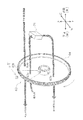
- FIG. 9 is a perspective view of the guide 69.
- FIG. 10 is a perspective view of the humidifying unit 60 to which the guide 69 is attached.
- FIG. 11 is a plan view of the air conditioning room outside unit 30 including the humidification unit 60 to which the guide 69 is attached, and shows a state where the top plate 48 of the air conditioning room outside unit 30 is removed. Note that the arrows shown in FIG. 11 indicate the flow of air passing through the moisture absorption region 63 a of the humidification rotor 63.
- the humidifying unit 60 may be provided with a guide 69 that constitutes a part of the moisture absorption path.
- the guide 69 should just be provided so that it may extend toward the outdoor heat exchanger 33 from the outer periphery of the humidification rotor 63, or its vicinity.
- the guide 69 may extend from the outer peripheral edge of the humidification rotor 63 to the vicinity of the outdoor heat exchanger 33.
- the tip of the guide 69 is in contact with the outdoor heat exchanger 33.
- the space between the moisture absorption area 63a of the humidification rotor 63 and the outdoor heat exchanger 33 may be configured as a closed space by the partition plate 43, the guide 69, and the top plate 48.
- the shape of the guide 69 is not particularly limited as long as the shape extends from the outer peripheral edge of the humidifying rotor 63 or the vicinity thereof toward the outdoor heat exchanger 33. Further, in the guide 69, when the end on the outdoor heat exchanger 33 side is the inlet side end and the end on the humidifying rotor 63 side is the outlet side end, the shape of the inlet side end is particularly the outdoor heat exchanger 33. It is preferable that the design is based on the capacity and the moisture absorption capacity of the humidification rotor 63.
- the guide 69 extending from the outer peripheral edge of the moisture absorption region 63 a of the humidification rotor 63 toward the outdoor heat exchanger 33, the outside air that has passed through the outdoor heat exchanger 33 is absorbed by the humidification rotor 63. It is possible to reach 63a and easily pass through the moisture absorption region 63a. As a result, it is possible to avoid a situation in which outside air does not pass through the moisture absorption region 63a of the humidification rotor 63 due to ventilation resistance. Thereby, the possibility that the moisture adsorption amount may be reduced in the humidification rotor 63 can be reduced.
- the present invention can prevent the performance degradation of the outdoor heat exchanger, and is effective when applied to an air-conditioning outdoor unit equipped with a humidifying unit.
- Air-conditioning outdoor unit 31 Compressor 33 Outdoor heat exchanger 33t Upper end of outdoor heat exchanger 39 Outdoor fan 40 Casing 60 Humidification unit 63 Humidification rotor (rotor) 63a Moisture absorption area 63b Moisture release area 63t Upper end of humidification rotor 65 Rotor drive motor 71 Heater
Landscapes
- Engineering & Computer Science (AREA)
- Chemical & Material Sciences (AREA)
- Combustion & Propulsion (AREA)
- Mechanical Engineering (AREA)
- General Engineering & Computer Science (AREA)
- Other Air-Conditioning Systems (AREA)
- Air Humidification (AREA)
- Central Air Conditioning (AREA)
Abstract
Description
寸法を大きくすることができる。
本発明の一実施形態に係る空調室外ユニット30を備える空気調和装置10は、図1に示すように、空調室外ユニット30の他に、空調室内ユニット20を備えており、空調室内ユニット20と空調室外ユニット30とが連絡配管12によって接続されて構成されている。この空気調和装置10は、冷房運転、暖房運転、除湿運転、加湿運転及び換気運転などの複数の運転モードを有しており、これらの運転モードを適宜組み合わせることもできる。
冷媒回路の動作は従来からあるものと変わらないが、図1に示す冷媒回路の動作について簡単に説明する。
(2-1)空調室内ユニット20の構成
空調室内ユニット20には、室内熱交換器21の他に、図1に示すように、モータで駆動される室内ファン22が室内熱交換器21の下流側に設けられている。室内ファン22としては、例えばクロスフローファンが採用される。室内ファン22が駆動されると、空調室内ユニット20上部の吸込口23から吸い込まれた室内空気が、室内熱交換器21を通過して空調室内ユニット20下部の吹出口24から吹き出される。
(2-2-1)空調室外ユニット30の構成の概要
空調室外ユニット30は、ケーシング40を備えている。そして、図1に示すように、ケーシング40の内部は、仕切板43によって送風機室S1と機械室S2とに分けられている。空調室外ユニット30では、送風機室S1から機械室S2に風が回り込まないように、送風機室S1と機械室S2とが仕切板43によって遮蔽されている。
図2は、空調室外ユニット30の正面図であり、空調室外ユニット30から電装品箱50、グリル及び前板46の一部が取り外された状態を示している。図3は、空調室外ユニット30の斜視図であり、電装品箱50の本体51、グリル及び天板48が取り外された空調室外ユニット30において、図2で取り外されている前板46の一部を仮想面とした状態を示している。図4は、空調室外ユニット30の平面図であり、空調室外ユニット30の天板48が取外された状態を示している。なお、図4に記載の矢印は、加湿ロータ63の吸湿領域63aを通る空気の流れを示している。
室外熱交換器33は、図3及び図4に示すように、上面視L型の形状を呈しており、ケーシング40の左側板45に正対する第1部分33aと、ケーシング40の背面を構成する保護金網に正対する第2部分33bとを有する。
室外ファン39は、室外熱交換器33の背面側(後方側)から室外熱交換器33を通して吸い込まれた外気を、空調室外ユニット30の正面側(前方側)に吹き出させるファンであって、本実施形態では、プロペラファンである。室外ファン39は、ファンモータ39aと、ファンモータ39aによって駆動されるプロペラ39bを有する。プロペラ39bは、その一部がベルマウス46aで囲まれた空間内に入るように配置されている。また、ファンモータ39aはプロペラ39bの背面側に取り付けられており、プロペラ39bの回転軸とファンモータ39aの駆動軸とが結合されている。さらに、ファンモータ39aは、ファンモータ台(図示せず)によって支持されている。ファンモータ台は、底板49及び室外熱交換器33の上端33tに固定された固定板(図示せず)に取り付けられている。
図5は、加湿ユニット60の分解図である。加湿ユニット60は、吸湿経路と放湿経路とを有しており、吸湿経路が空調室外ユニット30の送風機室S1に、放湿経路が空調室外ユニット30の機械室S2に位置するように配設されている。
加湿ロータ63は、1つの板状の吸放湿材である。なお、加湿ロータ63の形状は板状であればどのような形状であってもよい。本実施形態では、加湿ロータ63は、円盤状を呈するものとする。また、ここでいう1つの板状の吸放湿材には、単体の板状の吸放湿材が加湿ロータ63を構成しているものの他、同一形状又は異なる形状の吸放湿材が複数組み合わされて1つの板状の加湿ロータ63を構成しているものも含まれる。加湿ロータ63は、ゼオライト等の焼成によって形成されたハニカム構造のゼオライトロータである。加湿ロータ63は、円盤の中心を回転軸として回転するように取り付けられ、加湿ロータ63の周囲に設けられているギア64に伝達されるロータ駆動モータ65の動力によって回転駆動される。ロータ駆動モータ65は、その全体が機械室S2に配置されている。さらに、本実施形態では、ロータ駆動モータ65は、正面視において、加湿ロータ63と重ならないように、加湿ロータ63の外周よりも径方向外側に配置されている。
ヒータ71は、加湿ロータ63の放湿領域63bの側方に設けられている。ヒータ71は、筒状の筐体の中に電熱線(図示省略)が設けられた構造であり、吸入口72から吸入されて加湿ロータ63に送られる外気を電熱線で加熱する。加湿ロータ63では、加湿ロータ63のハニカム構造の開口を加熱された空気が通り抜けるときに、加湿ロータ63から放湿されることで、ターボファン75に吸い込まれる空気が加湿される。
ターボファン75は、空調室外ユニット30から空調室内ユニット20へと向かう空気流れを生成する。また、ターボファン75は、加湿ロータ63を挟んでヒータ71と対向ように配置されている。そして、電装品箱50は、ターボファン75及び加湿ロータ63を挟んでヒータ71とは反対側に配置されている。さらに、ターボファン75は、図2や図4に示すように、機械室S2に設置されている。
図6は、加湿ロータ63における空気流れを説明するための図である。図7は、加湿ロータ63の放湿領域63b、吸湿領域63a及び再熱領域63cを説明するための図である。なお、図7では、加湿ロータ63を正面から見た場合の放湿領域63b、吸湿領域63a及び再熱領域63cをそれぞれ示している。以下に、加湿運転時における空気の流れについて説明する。なお、空気調和装置10では、加湿運転は暖房運転と組み合わせて行われるものとする。このため、加湿運転時には、圧縮機31及び室外ファン39が駆動している。また、加湿運転時には、加湿ロータ63がロータ駆動モータ65の動力によって所定の回転速度で回転しており、ヒータ71及びターボファン75が駆動している。なお、加湿ロータ63は回転するので、吸湿領域63aでの吸湿によって加湿ロータ63に吸着された水分は加湿ロータ63の回転に伴って放湿領域63bに運ばれ、放湿領域63bでの放湿によって吸着されていた水分が脱着されることで放湿領域63bの周囲の空気が加湿される。また、本実施形態の加湿ロータ63は、正面から見て反計回りに回転しており、吸湿領域63aとして機能した部分が回転してヒータ支持部材74に対向する位置に来ると放湿領域63bとして機能する。
(4-1)
従来の空調室外ユニットには、加湿ロータが水平面に沿って配設されており、加湿ロータ全体が送風機室に位置していることで、室外熱交換器の一部が加湿ユニットで塞がれ、室外熱交換器において加湿ユニットで塞がれた部分を外気が通りにくくなり、室外熱交換器の性能が低下してしまうことがある。
本実施形態の加湿ロータ63の上端63tは、室外熱交換器33の上端33tよりも低い位置にある。このため、加湿ロータ63が、室外熱交換器33の上端33tよりも高い位置に配置されている場合と比較して、空調室外ユニット30の高さ寸法を抑えることができる。これにより、室外熱交換器33の能力を低減させずに製品サイズが大きくなるのを抑制することができている。
本実施形態では、ヒータ71、ロータ駆動モータ65、及び電装品箱50の本体51は、空調室外ユニット30の機械室S2に配置されている。このように電機部品が機械室S2にまとめて配置されていることで、配線の取り回しなど配線作業が簡易になる。これにより、空調室外ユニット30の組立性及びメンテナンス性(サービス性)を向上させることができている。
本実施形態では、加湿ロータ63と室外熱交換器33との間には隙間がある。このため、加湿ロータ63が室外熱交換器33に接触しないようにすることができる。これにより、加湿ロータ63の破損を防止することができている。特に、破損防止の観点から、本実施形態の加湿ロータ63のように回転する部材は室外熱交換器33に接触しないように構成することが好ましい。
本実施形態では、ヒータ71が、加湿ロータ63を挟んで電装品箱50とは反対側に配置されている。このように、空調室外ユニット30においてヒータ71が加湿ロータ63を挟んで電装品箱50とは反対側に配置されていることで、加湿ユニット60のヒータ71と電装品箱50とをできるだけ離隔することができる。このため、ヒータ71からの熱が電装品箱50に直接伝わりにくくなり、電装品箱50の本体51内の電子部品及び制御基板が熱により劣化するおそれを低減することができる。また、加湿ユニット60のヒータ71と電装品箱50とをできるだけ離隔することで、ヒータ71からの熱を電装品箱50に伝わり難くして、ヒートシンク52からの放熱が阻害されるおそれを低減することができる。
本実施形態では、ターボファン75が加湿ロータ63を挟んでヒータ71と対向ように配置されており、電装品箱50がターボファン75及び加湿ロータ63を挟んでヒータ71とは反対側に配置されている。このように、電装品箱50がターボファン75及び加湿ロータ63を挟んでヒータ71とは反対側に配置されていることで、ターボファン75の分だけさらにヒータ71と電装品箱50とを離隔させることができる。これにより、ヒータ71からの熱が電装品箱50に伝わるのをさらに抑制できる。
本実施形態では、ロータ駆動モータ65が機械室S2に配置されている。このため、室外ファン39の駆動によりロータ駆動モータ65が冷却されることがなく、これに起因するロータ駆動モータ65の異常を防ぐことができる。これによって、ロータ駆動モータ65の耐久性の確保を実現することができている。
本実施形態では、正面視において、電装品箱50の少なくとも一部が加湿ロータ63と重なるように配設されている。このため、例えば、加湿ロータ63と電装品箱50とが正面視において重ならないように左右に並んで配置されているよりも、ケーシング40の左右方向の寸法を小さくすることができる。
本実施形態では、加湿ロータ63及び電装品箱50それぞれが鉛直面に沿って配設されている。また、加湿ロータ63と電装品箱50とは、前後に並ぶように配置されている。このため、例えば、その長手方向が水平面に沿って延びるように電装品箱50が配設されている場合、すなわち電装品箱50が横置き配置されている場合よりも、ケーシング40の前後方向の幅寸法を小さくすることができる。これによって、空調室外ユニット30の薄型化を実現することができている。
本実施形態では、機械室S2が、前方に向かうにつれて左右方向の幅が広くなるように形成されている。また、電装品箱50は、機械室S2の内部前方に配置される。このため、電装品箱50が機械室S2の内部後方に配置されるよりも、電装品箱50の左右方向の寸法を大きくすることができる。これによって、電装品箱50の設計の自由度を向上させることができている。
(5-1)変形例A
上記実施形態の空調室外ユニット30では、後方から前方に向かって、加湿ユニット60、電装品箱50の順に配置されている。しかしながら、加湿ロータ63が仕切板43を跨ぐように配置されていれば、加湿ユニット60及び電装品箱50の位置関係はこれに限定されるものではなく、例えば、図8に示すように、後方から前方に向かって、電装品箱50、加湿ユニット60の順に配置されていてもよい。
上記実施形態の空調室外ユニット30では、室外ファン39が駆動することで、外気は、室外熱交換器33を通過した直後に加湿ロータ63の吸湿領域63aへと至っている。しかしながら、加湿ロータ63の吸湿領域63aを通る吸湿経路はこれに限定されるものではない。例えば、グリルの一部に閉鎖面を設け、室外ファン39によって生じる空気流れの一部が該閉鎖面に押し当たり、加湿ロータ63の吸湿領域63aへと至るようにしてもよい。
図9は、ガイド69の斜視図である。図10は、ガイド69が取り付けられた加湿ユニット60の斜視図である。図11は、ガイド69が取り付けられた加湿ユニット60を備える空調室外ユニット30の平面図であり、空調室外ユニット30の天板48が取外された状態を示している。なお、図11に記載の矢印は、加湿ロータ63の吸湿領域63aを通る空気の流れを示している。
31 圧縮機
33 室外熱交換器
33t 室外熱交換器の上端
39 室外ファン
40 ケーシング
60 加湿ユニット
63 加湿ロータ(ロータ)
63a 吸湿領域
63b 放湿領域
63t 加湿ロータの上端
65 ロータ駆動モータ
71 ヒータ
Claims (7)
- 内部が左右に並ぶ送風機室(S1)と機械室(S2)とに分かれるケーシング(40)と、
前記機械室に配置される圧縮機(31)と、
前記送風機室に配置される室外熱交換器(33)と、
前記送風機室に配置されており、前記室外熱交換器に外気を通す室外ファン(39)と、
外気中の水分を吸着する吸湿領域(63a)と加熱されることで前記吸湿領域に吸着した水分を放出する放湿領域(63b)とを含み鉛直面に沿って前記室外熱交換器よりも前方に配設される板状のロータ(63)、を有する加湿ユニット(60)と、
を備え、
前記ロータは、前記吸湿領域が前記送風機室に位置し、前記放湿領域が前記機械室に位置するように配置されており、
前記ロータを回転駆動させるロータ駆動モータ(65)の全体が、前記機械室に配置されている、
空調室外ユニット(30)。 - 前記圧縮機及び前記室外ファンを含む機器の制御を行うための電装品を収納する電装品箱(50)、
を備え、
前記電装品箱は、正面視において、少なくともその一部が前記ロータと重なるように配置されている、
請求項1に記載の空調室外ユニット。 - 前記電装品箱は、鉛直面に沿って配設されており、
前記電装品箱と前記ロータとは、前後に並ぶように配置されている、
請求項2に記載の空調室外ユニット。 - 前記機械室は、前方に向かうにつれて左右方向の幅が広くなるように形成されており、
前記電装品箱は、前記機械室の内部前方に配置されている、
請求項2又は3に記載の空調室外ユニット。 - 前記ロータは、その上端(63t)が、前記室外熱交換器の上端(33t)近傍、或いは前記室外熱交換器の上端よりも低い位置にあるように配置されている、
請求項1から4のいずれか1項に記載の空調室外ユニット。 - 前記加湿ユニットは、前記放湿領域を加熱するためのヒータ(71)、を有し、
前記ヒータは、前記機械室に配置される、
請求項1から5のいずれか1項に記載の空調室外ユニット。 - 前記室外熱交換器と前記ロータとの間には、隙間がある、
請求項1から6のいずれか1項に記載の空調室外ユニット。
Priority Applications (4)
| Application Number | Priority Date | Filing Date | Title |
|---|---|---|---|
| EP14847370.5A EP3054226B1 (en) | 2013-09-30 | 2014-08-26 | Air-conditioner outdoor unit |
| ES14847370.5T ES2660022T3 (es) | 2013-09-30 | 2014-08-26 | Unidad de exterior de acondicionamiento de aire |
| CN201480053431.2A CN105579781B (zh) | 2013-09-30 | 2014-08-26 | 空调室外单元 |
| AU2014325645A AU2014325645B2 (en) | 2013-09-30 | 2014-08-26 | Air-conditioning outdoor unit |
Applications Claiming Priority (2)
| Application Number | Priority Date | Filing Date | Title |
|---|---|---|---|
| JP2013204187 | 2013-09-30 | ||
| JP2013-204187 | 2013-09-30 |
Publications (1)
| Publication Number | Publication Date |
|---|---|
| WO2015045708A1 true WO2015045708A1 (ja) | 2015-04-02 |
Family
ID=52742860
Family Applications (1)
| Application Number | Title | Priority Date | Filing Date |
|---|---|---|---|
| PCT/JP2014/072259 Ceased WO2015045708A1 (ja) | 2013-09-30 | 2014-08-26 | 空調室外ユニット |
Country Status (6)
| Country | Link |
|---|---|
| EP (1) | EP3054226B1 (ja) |
| JP (1) | JP5800074B2 (ja) |
| CN (1) | CN105579781B (ja) |
| AU (1) | AU2014325645B2 (ja) |
| ES (1) | ES2660022T3 (ja) |
| WO (1) | WO2015045708A1 (ja) |
Families Citing this family (3)
| Publication number | Priority date | Publication date | Assignee | Title |
|---|---|---|---|---|
| JP2017083147A (ja) * | 2015-10-30 | 2017-05-18 | ダイキン工業株式会社 | 空調機の室外ユニット |
| JP2018179362A (ja) * | 2017-04-07 | 2018-11-15 | ダイキン工業株式会社 | 調湿ユニット |
| CN113418242A (zh) * | 2021-06-03 | 2021-09-21 | 重庆海尔空调器有限公司 | 无水加湿装置、空调器 |
Citations (2)
| Publication number | Priority date | Publication date | Assignee | Title |
|---|---|---|---|---|
| JP2010261711A (ja) * | 2010-07-20 | 2010-11-18 | Daikin Ind Ltd | 空気調和機 |
| JP2012251692A (ja) | 2011-06-01 | 2012-12-20 | Daikin Industries Ltd | 空気調和装置の室外機 |
Family Cites Families (5)
| Publication number | Priority date | Publication date | Assignee | Title |
|---|---|---|---|---|
| JP3567857B2 (ja) * | 2000-06-13 | 2004-09-22 | ダイキン工業株式会社 | 加湿装置およびそれを用いた空気調和機 |
| JP4677658B2 (ja) * | 2000-09-12 | 2011-04-27 | ダイキン工業株式会社 | 空気調和機 |
| JP2002089896A (ja) * | 2000-09-12 | 2002-03-27 | Daikin Ind Ltd | 空気調和機 |
| JP2003164721A (ja) * | 2001-11-29 | 2003-06-10 | Daikin Ind Ltd | 空気調和装置の加湿ユニット |
| CN1176330C (zh) * | 2001-12-20 | 2004-11-17 | 丁静 | 自动调节湿度空调装置及其用途 |
-
2014
- 2014-08-22 JP JP2014169016A patent/JP5800074B2/ja not_active Expired - Fee Related
- 2014-08-26 WO PCT/JP2014/072259 patent/WO2015045708A1/ja not_active Ceased
- 2014-08-26 ES ES14847370.5T patent/ES2660022T3/es active Active
- 2014-08-26 CN CN201480053431.2A patent/CN105579781B/zh not_active Expired - Fee Related
- 2014-08-26 AU AU2014325645A patent/AU2014325645B2/en not_active Ceased
- 2014-08-26 EP EP14847370.5A patent/EP3054226B1/en not_active Not-in-force
Patent Citations (2)
| Publication number | Priority date | Publication date | Assignee | Title |
|---|---|---|---|---|
| JP2010261711A (ja) * | 2010-07-20 | 2010-11-18 | Daikin Ind Ltd | 空気調和機 |
| JP2012251692A (ja) | 2011-06-01 | 2012-12-20 | Daikin Industries Ltd | 空気調和装置の室外機 |
Also Published As
| Publication number | Publication date |
|---|---|
| EP3054226A1 (en) | 2016-08-10 |
| ES2660022T3 (es) | 2018-03-20 |
| CN105579781B (zh) | 2017-08-25 |
| JP2015092130A (ja) | 2015-05-14 |
| CN105579781A (zh) | 2016-05-11 |
| JP5800074B2 (ja) | 2015-10-28 |
| EP3054226A4 (en) | 2016-12-14 |
| AU2014325645A1 (en) | 2016-04-28 |
| EP3054226B1 (en) | 2018-01-17 |
| AU2014325645B2 (en) | 2016-05-12 |
Similar Documents
| Publication | Publication Date | Title |
|---|---|---|
| JP5796618B2 (ja) | 空調室外ユニット | |
| JP5234205B2 (ja) | 空気調和装置の室外機 | |
| JP2016114344A (ja) | 空気調和機 | |
| JP5800074B2 (ja) | 空調室外ユニット | |
| JP5532100B2 (ja) | 空気調和装置の室外機 | |
| JP5672284B2 (ja) | 空気調和装置の室外機 | |
| JP5790162B2 (ja) | 空気調和装置の室外機 | |
| JP5532099B2 (ja) | 空気調和装置の室外機 | |
| JP5533970B2 (ja) | 空気調和装置の室外機 | |
| JP2015098997A (ja) | 加湿装置 | |
| WO2015046013A1 (ja) | 空調室外ユニット | |
| JP5910697B2 (ja) | 空気調和装置の室外機 | |
| JP2015098992A (ja) | 空調室外ユニット | |
| WO2015064537A1 (ja) | 空調室外ユニット | |
| JP5659954B2 (ja) | 空気調和装置の室外機 | |
| JP5862058B2 (ja) | 空気調和装置の室外機 | |
| JP2012251691A (ja) | 空気調和装置の室外機 | |
| WO2015076289A1 (ja) | 空調室外ユニット | |
| WO2015045684A1 (ja) | 空調室外ユニット | |
| CN110462297B (zh) | 调湿单元 |
Legal Events
| Date | Code | Title | Description |
|---|---|---|---|
| WWE | Wipo information: entry into national phase |
Ref document number: 201480053431.2 Country of ref document: CN |
|
| 121 | Ep: the epo has been informed by wipo that ep was designated in this application |
Ref document number: 14847370 Country of ref document: EP Kind code of ref document: A1 |
|
| NENP | Non-entry into the national phase |
Ref country code: DE |
|
| ENP | Entry into the national phase |
Ref document number: 2014325645 Country of ref document: AU Date of ref document: 20140826 Kind code of ref document: A |
|
| REEP | Request for entry into the european phase |
Ref document number: 2014847370 Country of ref document: EP |
|
| WWE | Wipo information: entry into national phase |
Ref document number: 2014847370 Country of ref document: EP |