WO2015046348A1 - プローブユニット、処置具及び処置システム - Google Patents
プローブユニット、処置具及び処置システム Download PDFInfo
- Publication number
- WO2015046348A1 WO2015046348A1 PCT/JP2014/075460 JP2014075460W WO2015046348A1 WO 2015046348 A1 WO2015046348 A1 WO 2015046348A1 JP 2014075460 W JP2014075460 W JP 2014075460W WO 2015046348 A1 WO2015046348 A1 WO 2015046348A1
- Authority
- WO
- WIPO (PCT)
- Prior art keywords
- treatment
- probe
- marking
- unit
- living tissue
- Prior art date
- Legal status (The legal status is an assumption and is not a legal conclusion. Google has not performed a legal analysis and makes no representation as to the accuracy of the status listed.)
- Ceased
Links
- 0 CCC*N1CC1 Chemical compound CCC*N1CC1 0.000 description 1
Images







Classifications
-
- A—HUMAN NECESSITIES
- A61—MEDICAL OR VETERINARY SCIENCE; HYGIENE
- A61B—DIAGNOSIS; SURGERY; IDENTIFICATION
- A61B17/00—Surgical instruments, devices or methods
- A61B17/32—Surgical cutting instruments
- A61B17/320068—Surgical cutting instruments using mechanical vibrations, e.g. ultrasonic
-
- A—HUMAN NECESSITIES
- A61—MEDICAL OR VETERINARY SCIENCE; HYGIENE
- A61B—DIAGNOSIS; SURGERY; IDENTIFICATION
- A61B1/00—Instruments for performing medical examinations of the interior of cavities or tubes of the body by visual or photographical inspection, e.g. endoscopes; Illuminating arrangements therefor
- A61B1/32—Devices for opening or enlarging the visual field, e.g. of a tube of the body
-
- A—HUMAN NECESSITIES
- A61—MEDICAL OR VETERINARY SCIENCE; HYGIENE
- A61B—DIAGNOSIS; SURGERY; IDENTIFICATION
- A61B17/00—Surgical instruments, devices or methods
- A61B17/02—Surgical instruments, devices or methods for holding wounds open, e.g. retractors; Tractors
- A61B17/025—Joint distractors
-
- A—HUMAN NECESSITIES
- A61—MEDICAL OR VETERINARY SCIENCE; HYGIENE
- A61B—DIAGNOSIS; SURGERY; IDENTIFICATION
- A61B17/00—Surgical instruments, devices or methods
- A61B17/16—Instruments for performing osteoclasis; Drills or chisels for bones; Trepans
-
- A—HUMAN NECESSITIES
- A61—MEDICAL OR VETERINARY SCIENCE; HYGIENE
- A61B—DIAGNOSIS; SURGERY; IDENTIFICATION
- A61B17/00—Surgical instruments, devices or methods
- A61B17/16—Instruments for performing osteoclasis; Drills or chisels for bones; Trepans
- A61B17/1604—Chisels; Rongeurs; Punches; Stamps
-
- A—HUMAN NECESSITIES
- A61—MEDICAL OR VETERINARY SCIENCE; HYGIENE
- A61B—DIAGNOSIS; SURGERY; IDENTIFICATION
- A61B17/00—Surgical instruments, devices or methods
- A61B17/16—Instruments for performing osteoclasis; Drills or chisels for bones; Trepans
- A61B17/1613—Component parts
-
- A—HUMAN NECESSITIES
- A61—MEDICAL OR VETERINARY SCIENCE; HYGIENE
- A61B—DIAGNOSIS; SURGERY; IDENTIFICATION
- A61B17/00—Surgical instruments, devices or methods
- A61B17/16—Instruments for performing osteoclasis; Drills or chisels for bones; Trepans
- A61B17/1613—Component parts
- A61B17/1628—Motors; Power supplies
-
- A—HUMAN NECESSITIES
- A61—MEDICAL OR VETERINARY SCIENCE; HYGIENE
- A61B—DIAGNOSIS; SURGERY; IDENTIFICATION
- A61B17/00—Surgical instruments, devices or methods
- A61B17/16—Instruments for performing osteoclasis; Drills or chisels for bones; Trepans
- A61B17/1613—Component parts
- A61B17/1633—Sleeves, i.e. non-rotating parts surrounding the bit shaft, e.g. the sleeve forming a single unit with the bit shaft
-
- A—HUMAN NECESSITIES
- A61—MEDICAL OR VETERINARY SCIENCE; HYGIENE
- A61B—DIAGNOSIS; SURGERY; IDENTIFICATION
- A61B17/00—Surgical instruments, devices or methods
- A61B17/16—Instruments for performing osteoclasis; Drills or chisels for bones; Trepans
- A61B17/1657—Bone breaking devices
-
- A—HUMAN NECESSITIES
- A61—MEDICAL OR VETERINARY SCIENCE; HYGIENE
- A61B—DIAGNOSIS; SURGERY; IDENTIFICATION
- A61B17/00—Surgical instruments, devices or methods
- A61B17/16—Instruments for performing osteoclasis; Drills or chisels for bones; Trepans
- A61B17/1659—Surgical rasps, files, planes, or scrapers
-
- A—HUMAN NECESSITIES
- A61—MEDICAL OR VETERINARY SCIENCE; HYGIENE
- A61B—DIAGNOSIS; SURGERY; IDENTIFICATION
- A61B17/00—Surgical instruments, devices or methods
- A61B17/16—Instruments for performing osteoclasis; Drills or chisels for bones; Trepans
- A61B17/17—Guides or aligning means for drills, mills, pins or wires
-
- A—HUMAN NECESSITIES
- A61—MEDICAL OR VETERINARY SCIENCE; HYGIENE
- A61B—DIAGNOSIS; SURGERY; IDENTIFICATION
- A61B17/00—Surgical instruments, devices or methods
- A61B17/16—Instruments for performing osteoclasis; Drills or chisels for bones; Trepans
- A61B17/17—Guides or aligning means for drills, mills, pins or wires
- A61B17/1732—Guides or aligning means for drills, mills, pins or wires for bone breaking devices
-
- A—HUMAN NECESSITIES
- A61—MEDICAL OR VETERINARY SCIENCE; HYGIENE
- A61B—DIAGNOSIS; SURGERY; IDENTIFICATION
- A61B17/00—Surgical instruments, devices or methods
- A61B17/16—Instruments for performing osteoclasis; Drills or chisels for bones; Trepans
- A61B17/17—Guides or aligning means for drills, mills, pins or wires
- A61B17/1735—Guides or aligning means for drills, mills, pins or wires for rasps or chisels
-
- A—HUMAN NECESSITIES
- A61—MEDICAL OR VETERINARY SCIENCE; HYGIENE
- A61B—DIAGNOSIS; SURGERY; IDENTIFICATION
- A61B17/00—Surgical instruments, devices or methods
- A61B17/22—Implements for squeezing-off ulcers or the like on inner organs of the body; Implements for scraping-out cavities of body organs, e.g. bones; for invasive removal or destruction of calculus using mechanical vibrations; for removing obstructions in blood vessels, not otherwise provided for
-
- A—HUMAN NECESSITIES
- A61—MEDICAL OR VETERINARY SCIENCE; HYGIENE
- A61B—DIAGNOSIS; SURGERY; IDENTIFICATION
- A61B17/00—Surgical instruments, devices or methods
- A61B17/22—Implements for squeezing-off ulcers or the like on inner organs of the body; Implements for scraping-out cavities of body organs, e.g. bones; for invasive removal or destruction of calculus using mechanical vibrations; for removing obstructions in blood vessels, not otherwise provided for
- A61B17/22004—Implements for squeezing-off ulcers or the like on inner organs of the body; Implements for scraping-out cavities of body organs, e.g. bones; for invasive removal or destruction of calculus using mechanical vibrations; for removing obstructions in blood vessels, not otherwise provided for using mechanical vibrations, e.g. ultrasonic shock waves
-
- A—HUMAN NECESSITIES
- A61—MEDICAL OR VETERINARY SCIENCE; HYGIENE
- A61B—DIAGNOSIS; SURGERY; IDENTIFICATION
- A61B17/00—Surgical instruments, devices or methods
- A61B17/32—Surgical cutting instruments
-
- A—HUMAN NECESSITIES
- A61—MEDICAL OR VETERINARY SCIENCE; HYGIENE
- A61B—DIAGNOSIS; SURGERY; IDENTIFICATION
- A61B90/00—Instruments, implements or accessories specially adapted for surgery or diagnosis and not covered by any of the groups A61B1/00 - A61B50/00, e.g. for luxation treatment or for protecting wound edges
- A61B90/36—Image-producing devices or illumination devices not otherwise provided for
- A61B90/361—Image-producing devices, e.g. surgical cameras
-
- A—HUMAN NECESSITIES
- A61—MEDICAL OR VETERINARY SCIENCE; HYGIENE
- A61B—DIAGNOSIS; SURGERY; IDENTIFICATION
- A61B90/00—Instruments, implements or accessories specially adapted for surgery or diagnosis and not covered by any of the groups A61B1/00 - A61B50/00, e.g. for luxation treatment or for protecting wound edges
- A61B90/36—Image-producing devices or illumination devices not otherwise provided for
- A61B90/37—Surgical systems with images on a monitor during operation
-
- A—HUMAN NECESSITIES
- A61—MEDICAL OR VETERINARY SCIENCE; HYGIENE
- A61C—DENTISTRY; APPARATUS OR METHODS FOR ORAL OR DENTAL HYGIENE
- A61C1/00—Dental machines for boring or cutting ; General features of dental machines or apparatus, e.g. hand-piece design
- A61C1/02—Dental machines for boring or cutting ; General features of dental machines or apparatus, e.g. hand-piece design characterised by the drive of the dental tools
- A61C1/07—Dental machines for boring or cutting ; General features of dental machines or apparatus, e.g. hand-piece design characterised by the drive of the dental tools with vibratory drive, e.g. ultrasonic waves
-
- A—HUMAN NECESSITIES
- A61—MEDICAL OR VETERINARY SCIENCE; HYGIENE
- A61M—DEVICES FOR INTRODUCING MEDIA INTO, OR ONTO, THE BODY; DEVICES FOR TRANSDUCING BODY MEDIA OR FOR TAKING MEDIA FROM THE BODY; DEVICES FOR PRODUCING OR ENDING SLEEP OR STUPOR
- A61M29/00—Dilators with or without means for introducing media, e.g. remedies
-
- A—HUMAN NECESSITIES
- A61—MEDICAL OR VETERINARY SCIENCE; HYGIENE
- A61B—DIAGNOSIS; SURGERY; IDENTIFICATION
- A61B17/00—Surgical instruments, devices or methods
- A61B2017/00367—Details of actuation of instruments, e.g. relations between pushing buttons, or the like, and activation of the tool, working tip, or the like
- A61B2017/00371—Multiple actuation, e.g. pushing of two buttons, or two working tips becoming operational
-
- A—HUMAN NECESSITIES
- A61—MEDICAL OR VETERINARY SCIENCE; HYGIENE
- A61B—DIAGNOSIS; SURGERY; IDENTIFICATION
- A61B17/00—Surgical instruments, devices or methods
- A61B2017/00367—Details of actuation of instruments, e.g. relations between pushing buttons, or the like, and activation of the tool, working tip, or the like
- A61B2017/00371—Multiple actuation, e.g. pushing of two buttons, or two working tips becoming operational
- A61B2017/00384—Actuation of one tool by pushing two buttons simultaneously
-
- A—HUMAN NECESSITIES
- A61—MEDICAL OR VETERINARY SCIENCE; HYGIENE
- A61B—DIAGNOSIS; SURGERY; IDENTIFICATION
- A61B17/00—Surgical instruments, devices or methods
- A61B2017/00367—Details of actuation of instruments, e.g. relations between pushing buttons, or the like, and activation of the tool, working tip, or the like
- A61B2017/00389—Button or wheel for performing multiple functions, e.g. rotation of shaft and end effector
- A61B2017/00393—Button or wheel for performing multiple functions, e.g. rotation of shaft and end effector with means for switching between functions
-
- A—HUMAN NECESSITIES
- A61—MEDICAL OR VETERINARY SCIENCE; HYGIENE
- A61B—DIAGNOSIS; SURGERY; IDENTIFICATION
- A61B17/00—Surgical instruments, devices or methods
- A61B2017/00367—Details of actuation of instruments, e.g. relations between pushing buttons, or the like, and activation of the tool, working tip, or the like
- A61B2017/00398—Details of actuation of instruments, e.g. relations between pushing buttons, or the like, and activation of the tool, working tip, or the like using powered actuators, e.g. stepper motors, solenoids
-
- A—HUMAN NECESSITIES
- A61—MEDICAL OR VETERINARY SCIENCE; HYGIENE
- A61B—DIAGNOSIS; SURGERY; IDENTIFICATION
- A61B17/00—Surgical instruments, devices or methods
- A61B17/02—Surgical instruments, devices or methods for holding wounds open, e.g. retractors; Tractors
- A61B17/025—Joint distractors
- A61B2017/0256—Joint distractors for the spine
-
- A—HUMAN NECESSITIES
- A61—MEDICAL OR VETERINARY SCIENCE; HYGIENE
- A61B—DIAGNOSIS; SURGERY; IDENTIFICATION
- A61B17/00—Surgical instruments, devices or methods
- A61B17/02—Surgical instruments, devices or methods for holding wounds open, e.g. retractors; Tractors
- A61B17/025—Joint distractors
- A61B2017/0268—Joint distractors for the knee
-
- A—HUMAN NECESSITIES
- A61—MEDICAL OR VETERINARY SCIENCE; HYGIENE
- A61B—DIAGNOSIS; SURGERY; IDENTIFICATION
- A61B17/00—Surgical instruments, devices or methods
- A61B17/02—Surgical instruments, devices or methods for holding wounds open, e.g. retractors; Tractors
- A61B17/025—Joint distractors
- A61B2017/0275—Joint distractors for the hip
-
- A—HUMAN NECESSITIES
- A61—MEDICAL OR VETERINARY SCIENCE; HYGIENE
- A61B—DIAGNOSIS; SURGERY; IDENTIFICATION
- A61B17/00—Surgical instruments, devices or methods
- A61B17/22—Implements for squeezing-off ulcers or the like on inner organs of the body; Implements for scraping-out cavities of body organs, e.g. bones; for invasive removal or destruction of calculus using mechanical vibrations; for removing obstructions in blood vessels, not otherwise provided for
- A61B17/22004—Implements for squeezing-off ulcers or the like on inner organs of the body; Implements for scraping-out cavities of body organs, e.g. bones; for invasive removal or destruction of calculus using mechanical vibrations; for removing obstructions in blood vessels, not otherwise provided for using mechanical vibrations, e.g. ultrasonic shock waves
- A61B2017/22005—Effects, e.g. on tissue
-
- A—HUMAN NECESSITIES
- A61—MEDICAL OR VETERINARY SCIENCE; HYGIENE
- A61B—DIAGNOSIS; SURGERY; IDENTIFICATION
- A61B17/00—Surgical instruments, devices or methods
- A61B17/22—Implements for squeezing-off ulcers or the like on inner organs of the body; Implements for scraping-out cavities of body organs, e.g. bones; for invasive removal or destruction of calculus using mechanical vibrations; for removing obstructions in blood vessels, not otherwise provided for
- A61B17/22004—Implements for squeezing-off ulcers or the like on inner organs of the body; Implements for scraping-out cavities of body organs, e.g. bones; for invasive removal or destruction of calculus using mechanical vibrations; for removing obstructions in blood vessels, not otherwise provided for using mechanical vibrations, e.g. ultrasonic shock waves
- A61B2017/22005—Effects, e.g. on tissue
- A61B2017/22011—Combined types of vibration, e.g. ultrasonic and electrohydraulic
-
- A—HUMAN NECESSITIES
- A61—MEDICAL OR VETERINARY SCIENCE; HYGIENE
- A61B—DIAGNOSIS; SURGERY; IDENTIFICATION
- A61B17/00—Surgical instruments, devices or methods
- A61B17/28—Surgical forceps
- A61B17/29—Forceps for use in minimally invasive surgery
- A61B2017/2926—Details of heads or jaws
- A61B2017/2927—Details of heads or jaws the angular position of the head being adjustable with respect to the shaft
- A61B2017/2929—Details of heads or jaws the angular position of the head being adjustable with respect to the shaft with a head rotatable about the longitudinal axis of the shaft
-
- A—HUMAN NECESSITIES
- A61—MEDICAL OR VETERINARY SCIENCE; HYGIENE
- A61B—DIAGNOSIS; SURGERY; IDENTIFICATION
- A61B17/00—Surgical instruments, devices or methods
- A61B17/32—Surgical cutting instruments
- A61B17/320016—Endoscopic cutting instruments, e.g. arthroscopes, resectoscopes
- A61B17/32002—Endoscopic cutting instruments, e.g. arthroscopes, resectoscopes with continuously rotating, oscillating or reciprocating cutting instruments
- A61B2017/320028—Endoscopic cutting instruments, e.g. arthroscopes, resectoscopes with continuously rotating, oscillating or reciprocating cutting instruments with reciprocating movements
-
- A—HUMAN NECESSITIES
- A61—MEDICAL OR VETERINARY SCIENCE; HYGIENE
- A61B—DIAGNOSIS; SURGERY; IDENTIFICATION
- A61B17/00—Surgical instruments, devices or methods
- A61B17/32—Surgical cutting instruments
- A61B2017/320052—Guides for cutting instruments
-
- A—HUMAN NECESSITIES
- A61—MEDICAL OR VETERINARY SCIENCE; HYGIENE
- A61B—DIAGNOSIS; SURGERY; IDENTIFICATION
- A61B17/00—Surgical instruments, devices or methods
- A61B17/32—Surgical cutting instruments
- A61B17/320068—Surgical cutting instruments using mechanical vibrations, e.g. ultrasonic
- A61B2017/320071—Surgical cutting instruments using mechanical vibrations, e.g. ultrasonic with articulating means for working tip
-
- A—HUMAN NECESSITIES
- A61—MEDICAL OR VETERINARY SCIENCE; HYGIENE
- A61B—DIAGNOSIS; SURGERY; IDENTIFICATION
- A61B17/00—Surgical instruments, devices or methods
- A61B17/32—Surgical cutting instruments
- A61B17/320068—Surgical cutting instruments using mechanical vibrations, e.g. ultrasonic
- A61B2017/320072—Working tips with special features, e.g. extending parts
-
- A—HUMAN NECESSITIES
- A61—MEDICAL OR VETERINARY SCIENCE; HYGIENE
- A61B—DIAGNOSIS; SURGERY; IDENTIFICATION
- A61B17/00—Surgical instruments, devices or methods
- A61B17/32—Surgical cutting instruments
- A61B17/320068—Surgical cutting instruments using mechanical vibrations, e.g. ultrasonic
- A61B2017/320072—Working tips with special features, e.g. extending parts
- A61B2017/320074—Working tips with special features, e.g. extending parts blade
-
- A—HUMAN NECESSITIES
- A61—MEDICAL OR VETERINARY SCIENCE; HYGIENE
- A61B—DIAGNOSIS; SURGERY; IDENTIFICATION
- A61B17/00—Surgical instruments, devices or methods
- A61B17/32—Surgical cutting instruments
- A61B17/320068—Surgical cutting instruments using mechanical vibrations, e.g. ultrasonic
- A61B2017/320072—Working tips with special features, e.g. extending parts
- A61B2017/320074—Working tips with special features, e.g. extending parts blade
- A61B2017/320075—Working tips with special features, e.g. extending parts blade single edge blade, e.g. for cutting
-
- A—HUMAN NECESSITIES
- A61—MEDICAL OR VETERINARY SCIENCE; HYGIENE
- A61B—DIAGNOSIS; SURGERY; IDENTIFICATION
- A61B17/00—Surgical instruments, devices or methods
- A61B17/32—Surgical cutting instruments
- A61B17/320068—Surgical cutting instruments using mechanical vibrations, e.g. ultrasonic
- A61B2017/320089—Surgical cutting instruments using mechanical vibrations, e.g. ultrasonic node location
-
- A—HUMAN NECESSITIES
- A61—MEDICAL OR VETERINARY SCIENCE; HYGIENE
- A61B—DIAGNOSIS; SURGERY; IDENTIFICATION
- A61B17/00—Surgical instruments, devices or methods
- A61B17/34—Trocars; Puncturing needles
- A61B2017/348—Means for supporting the trocar against the body or retaining the trocar inside the body
-
- A—HUMAN NECESSITIES
- A61—MEDICAL OR VETERINARY SCIENCE; HYGIENE
- A61B—DIAGNOSIS; SURGERY; IDENTIFICATION
- A61B17/00—Surgical instruments, devices or methods
- A61B17/34—Trocars; Puncturing needles
- A61B2017/348—Means for supporting the trocar against the body or retaining the trocar inside the body
- A61B2017/3482—Means for supporting the trocar against the body or retaining the trocar inside the body inside
-
- A—HUMAN NECESSITIES
- A61—MEDICAL OR VETERINARY SCIENCE; HYGIENE
- A61B—DIAGNOSIS; SURGERY; IDENTIFICATION
- A61B17/00—Surgical instruments, devices or methods
- A61B17/34—Trocars; Puncturing needles
- A61B2017/348—Means for supporting the trocar against the body or retaining the trocar inside the body
- A61B2017/3482—Means for supporting the trocar against the body or retaining the trocar inside the body inside
- A61B2017/3484—Anchoring means, e.g. spreading-out umbrella-like structure
-
- A—HUMAN NECESSITIES
- A61—MEDICAL OR VETERINARY SCIENCE; HYGIENE
- A61B—DIAGNOSIS; SURGERY; IDENTIFICATION
- A61B17/00—Surgical instruments, devices or methods
- A61B17/34—Trocars; Puncturing needles
- A61B2017/348—Means for supporting the trocar against the body or retaining the trocar inside the body
- A61B2017/3482—Means for supporting the trocar against the body or retaining the trocar inside the body inside
- A61B2017/3484—Anchoring means, e.g. spreading-out umbrella-like structure
- A61B2017/3486—Balloon
Definitions
- the present invention relates to a probe unit, a treatment tool, and a treatment system used for treating a living tissue using ultrasonic vibration.
- the treatment target site should be marked in advance.
- a treatment instrument disclosed in Japanese Patent Application Laid-Open No. 2004-237100 can be used as another instrument.
- the flow of treatment in this case is to perform marking by accessing a treatment target site through an introduction conduit (port) while observing a treatment target site with an endoscope or the like. Thereafter, the treatment tool for marking is extracted from the introduction conduit, the treatment tool for treating the treatment target is placed in the introduction conduit, the site to be treated is accessed, and treatment is performed according to the marked position.
- a treatment tool that performs marking in order to define a site to be treated, and a treatment tool that has a probe for treating the marked treatment object are replaced from one introduction conduit. Is going. For this reason, it takes time to perform the operation of treating the treatment target.
- An object of the present invention is to provide a probe unit, a treatment tool, and a treatment system that can mark a site to be treated and can treat the marked treatment target.
- a probe unit used to treat a treatment target site of a biological tissue by ultrasonic vibration includes a vibration transmission unit that transmits ultrasonic vibration from a proximal end side to a distal end side; A probe having a treatment portion disposed on the distal end side of the vibration transmission portion and capable of treating the treatment target site by ultrasonic vibration transmitted through the vibration transmission portion; and a surface portion provided in the treatment portion; And a protruding marking portion that can be marked so as to define the treatment target site to be treated by the treatment portion on the living tissue by ultrasonic vibration transmitted to the treatment portion.
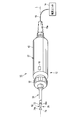
- FIG. 1 is a schematic view showing a treatment system according to the first embodiment.
- FIG. 2 is a schematic partial longitudinal sectional view showing the treatment tool of the treatment system according to the first embodiment.
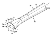
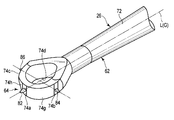
- FIG. 3A is a schematic perspective view showing a hook-type treatment portion and a marking portion of the probe unit of the treatment tool of the treatment system according to the first embodiment.
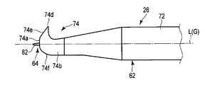
- FIG. 3B is a schematic side view showing a hook-type treatment portion and a marking portion of the probe unit of the treatment tool of the treatment system according to the first embodiment.
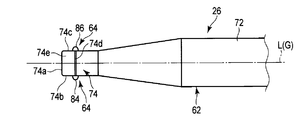
- FIG. 3C is a schematic top view showing a hook-type treatment portion and a marking portion of the probe unit of the treatment tool of the treatment system according to the first embodiment.
- FIG. 3A is a schematic perspective view showing a hook-type treatment portion and a marking portion of the probe unit of the treatment tool of the treatment system according to the first embodiment.
- FIG. 3B is a schematic side view showing a hook-type treatment portion and a marking portion of the probe unit of the treatment tool of the
- FIG. 4A is a marking portion provided on the distal end surface of the hook-type treatment portion of the probe unit of the treatment system of the treatment system according to the first embodiment, and a hole is made by ultrasonic vibration on the surface of the living tissue. It is the schematic which shows the state which has spaced the front end surface of the treatment part with respect to the surface of a biological tissue sometimes.
- FIG. 4B is a marking portion provided on the distal end surface of the hook-type treatment portion of the probe unit of the treatment system of the treatment system according to the first embodiment, and a hole is made by ultrasonic vibration on the surface of the living tissue. It is the schematic which shows the state which has contacted the front end surface of the treatment part with the surface of a biological tissue sometimes.
- FIG. 4A is a marking portion provided on the distal end surface of the hook-type treatment portion of the probe unit of the treatment system of the treatment system according to the first embodiment, and a hole is made by ultrasonic vibration on the surface of the living tissue. It is the schematic which shows the state
- FIG. 5 is a schematic view showing a state where dots are marked in the marking portions shown in FIGS. 3A to 4B so as to define the treatment target site of the living tissue using the treatment system according to the first embodiment.
- FIG. 6A is a schematic perspective view showing a hook-type treatment portion of a probe unit of a treatment tool of a treatment system according to a first modification of the first embodiment, and a knife-shaped marking portion having a different width and thickness.
- FIG. FIG. 6B is a schematic side view showing a hook-type treatment portion of the probe unit of the treatment tool of the treatment system according to the first modification of the first embodiment and a knife-shaped marking portion capable of recognizing the thickness. is there.
- FIG. 6A is a schematic perspective view showing a hook-type treatment portion of a probe unit of a treatment tool of a treatment system according to a first modification of the first embodiment, and a knife-shaped marking portion having a different width and thickness.
- FIG. 6B is a schematic side view showing a hook-
- FIG. 6C is a schematic top view showing a hook-type treatment portion of the probe unit of the treatment tool of the treatment system according to the first modification of the first embodiment and a knife-shaped marking portion that can recognize the width.
- FIG. 7A shows a linear shape of the living tissue by moving the gripping portion in the same direction as the width direction of the marker so as to define the treatment target site of the living tissue using the treatment system according to the first modification of the first embodiment. It is the schematic which shows the state marked to.
- FIG. 7B is a schematic diagram illustrating a state in which dots are marked so as to define a treatment target site of a living tissue using the treatment system according to the first modification of the first embodiment.
- FIG. 8A is a schematic side view showing a hook-type treatment portion and a marking portion of the probe unit of the treatment tool of the treatment system according to the second modification of the first embodiment.
- FIG. 8B is a schematic top view showing a hook-type treatment portion and a marking portion of the probe unit of the treatment tool of the treatment system according to the second modification of the first embodiment.
- FIG. 9A is a schematic side view showing a hook-type treatment portion and a marking portion of the probe unit of the treatment tool of the treatment system according to the third modification of the first embodiment.
- FIG. 9B is a schematic top view showing a hook-type treatment portion and a marking portion of the probe unit of the treatment tool of the treatment system according to a further modification of the third modification of the first embodiment.
- FIG. 10A is a schematic perspective view showing a rake-type treatment portion and a marking portion of the probe unit of the treatment tool of the treatment system according to the fourth modification example of the first embodiment.
- FIG. 10B is a schematic perspective view showing a rake type treatment portion and a marking portion of the probe unit of the treatment tool of the treatment system according to a further variation of the fourth variation of the first embodiment.
- FIG. 11A is a schematic perspective view showing a curette type treatment portion and a marking portion of a probe unit of a treatment tool of a treatment system according to a fifth modification of the first embodiment.
- FIG. 10A is a schematic perspective view showing a rake-type treatment portion and a marking portion of the probe unit of the treatment tool of the treatment system according to the fourth modification example of the first embodiment.
- FIG. 10B is a schematic perspective view showing a rake type treatment portion and a marking portion of the probe unit of the treatment tool of the treatment system according to a further variation of the fourth variation of the first embodiment
- FIG. 11B is a schematic perspective view showing a curette type treatment portion and a marking portion of the probe unit of the treatment tool of the treatment system according to a further variation of the fifth variation of the first embodiment.
- FIG. 12 is a schematic partial longitudinal sectional view showing a treatment system according to the second embodiment.
- FIG. 13A is a schematic side view showing a hook-type treatment portion of the probe unit of the treatment tool of the treatment system according to the second embodiment and a marking portion in a state of protruding from the distal end of the treatment portion.
- FIG. 13B is a schematic top view showing the hook-type treatment portion of the probe unit of the treatment tool of the treatment system according to the second embodiment and the marking portion in a state of protruding from the distal end of the treatment portion.
- a treatment system 10 includes a treatment tool 12 used for treating a living tissue (for example, bone, cartilage, etc.), a power supply unit (controller) 14, a foot switch, And a switch unit 16 such as a hand switch.
- the treatment instrument 12 and the power supply unit 14 are connected via a cable 18.
- the cable 18 transmits / receives a signal from the switch unit 16 to the power supply unit 14, and supplies power controlled by the power supply unit 14 to an ultrasonic transducer 52 described later of the treatment instrument 12.
- the cable 18 extends from the cable protector 18 a at the proximal end of the treatment instrument 12, and a connector (not shown) at the distal end of the cable 18 is detachable from the power supply unit 14.
- the switch unit 16 is described as a hand switch disposed on the grasping unit 22 of the treatment instrument 12, but a foot switch (not shown) connected to the power supply unit 14 is also preferably used. .
- the treatment instrument 12 includes a grip portion 22 that is gripped by a user, an ultrasonic transducer unit 24, and a probe unit 26.
- the treatment instrument 12 supports the probe unit 26, the ultrasonic transducer unit 24 that transmits ultrasonic vibrations to the probe unit 26, and the ultrasonic transducer unit 24, and the grip portion 22 that is gripped by the user. And have.
- the grip portion 22 has a central axis on the longitudinal axis L defined by the probe unit 26.
- a transducer unit 24, a probe unit 26, and a tubular body (sheath) 30 are disposed with respect to the grip portion 22 with the longitudinal axis L as a center.
- the grip portion 22 has a cylindrical outer case 42 that is preferably electrically insulating.
- the ultrasonic transducer unit 24 is supported inside the outer case 42.
- the vibrator unit 24 expands the amplitude of the ultrasonic vibration generated by the ultrasonic vibrator 52 and the ultrasonic vibrator 52 that generates ultrasonic vibration by supplying appropriate power from the power supply unit 14 shown in FIG. And a conical horn 54. That is, the transducer unit 24 generates ultrasonic vibrations according to the supply of power.
- the ultrasonic transducer 52 is, for example, a BLT type including a plurality of piezoelectric elements.
- the horn 54 is attached to the male screw 26 a at the base end of the probe unit 26 by a connection screw (female screw) 56.
- the horn 54 includes an outer flange 54 a that protrudes radially outward with respect to the longitudinal axis L of the horn 54.
- the outer flange 54a is in a vibration node position when ultrasonic vibration is transmitted from the ultrasonic vibrator 52.
- the outer case 42 is formed with an inner flange 42a that protrudes radially inward from the inner peripheral surface.
- the outer case 42 is disposed between the grip portion 22 and the ultrasonic transducer unit 24, and supports the ultrasonic transducer unit 24 at the node position of the ultrasonic vibration.
- the ultrasonic transducer unit 24 is supported inside the outer case 42
- the ultrasonic transducer unit 24 is detachable from the outer case 42. is there.
- the probe unit 26 shown in FIGS. 1 to 3C is designed so that the entire length is an integer multiple of a half wavelength of ultrasonic vibration.
- the probe unit 26 includes a rod-like probe 62 made of a metal such as a titanium alloy material, and a protruding marking portion 64 provided on the probe 62.
- the probe 62 has a rod-shaped probe main body (vibration transmitting portion) 72 and a treatment portion 74 provided on the distal end side of the probe main body 72.
- the ultrasonic vibration generated by the ultrasonic vibrator 52 is transmitted from the proximal end side to the distal end side of the probe main body 72 with the amplitude being enlarged by the horn 54, and is transmitted to the treatment section 74 through the probe main body 72.
- the treatment unit 74 can treat the treatment target site by ultrasonic vibration transmitted through the probe main body (vibration transmission unit) 72. For this reason, the probe 62 can transmit the ultrasonic vibration from the ultrasonic transducer unit 24, and can treat the living tissue by the action of the ultrasonic vibration transmitted to the treatment portion 74 at the distal end thereof.
- the tubular body 30 is formed of a cylindrical body.
- the tubular body 30 is provided on the distal end side of the grasping portion 22, and the treatment portion 74 at the distal end portion of the probe unit 26 is disposed on the distal end side with respect to the distal end 30a of the tubular body 30, and is exposed.
- the outer periphery of the probe main body 72 is covered.
- the tubular body 30 has a core material made of a material having rigidity such as a stainless alloy material, and the outer surface and the inner surface of the core material are each coated with a material having electrical insulation properties such as PTFE.
- a spacer is preferably disposed between the inner peripheral surface of the tubular body 30 and the vibration node position of the probe main body 72.
- the treatment portion 74 is formed in a hook shape.
- the treatment portion 74 includes a distal end (distal surface) 74a, a pair of side surfaces (surface portions) 74b and 74c, and a blade surface region (treatment surface) 74d formed on the proximal end side with respect to the distal end surface (surface portion) 74a.
- the front end surface 74a is formed as a flat portion.
- the longitudinal axis L intersects the distal end surface 74a, and the side surfaces 74b and 74c are located away from the longitudinal axis L.
- the tip surface 74a is preferably coated with a low friction that lowers the frictional force against the living tissue than other parts.
- the blade surface region 74d is located at or near the antinode position of the ultrasonic vibration, and can cut the abutted living tissue by transmitting the ultrasonic vibration in the abutting state with the living tissue.
- the continuous surface between the front end surface 74a and the blade surface region 74d indicated by reference numeral 74e is appropriately formed as a flat surface or a curved surface.
- a continuous surface 74f that is on the opposite side to the blade surface region (treatment surface) 74d, is orthogonal to the side surfaces 74b and 74c, and continues to the distal end surface 74a is formed as a curved surface.
- the boundary between the tip surface 74a and the continuous surface 74e, and the boundary between the tip surface 74a and the continuous surface 74f are formed as obtuse angles close to 180 ° that are larger than 90 ° and smaller than 180 °. ing. For this reason, the front end surface 74a and the continuous surface 74e and the front end surface 74a and the continuous surface 74f are smoothly continuous. In other words, there are no edges between the tip surface 74a and the continuous surface 74e and between the tip surface 74a and the continuous surface 74f. Of the continuous surfaces 74e and 74f, it is preferable that the position close to the tip surface 74a is also coated with low friction continuously after the coating of the tip surface 74a.
- the marking part 64 shown in FIGS. 3A to 3C is preferably integrated with the treatment part 74 of the probe 62.
- the marking portion 64 has a marker (protrusion) 82 that protrudes toward the distal end side with respect to the treatment portion 74 along the longitudinal axis L on the distal end surface 74 a of the treatment portion 74.
- the marking portion 64 has a longitudinal axis L defined by the probe main body 72 and the treatment portion 74, and the marking portion 64 is disposed on the distal end side along the longitudinal axis L of the treatment portion 74. For this reason, the marking part 64 is arrange
- the marking unit 64 can be marked so as to define a treatment target site to be treated by the treatment unit 74 on the living tissue by ultrasonic vibration transmitted to the treatment unit 74.
- the size (surface area) of the tip of the marker 82 of the marking portion 64 is sufficiently smaller than the surface area of the tip surface 74 a of the treatment portion 74 of the probe 62.
- the marker 82 is formed as a protrusion that protrudes with respect to the distal end surface 74 a of the treatment portion 74.
- the marker 82 is formed in, for example, a tapered shape, a hemispherical shape, or a substantially elliptical cone shape that tapers toward the tip, for example, when marking a living tissue such as bone or cartilage. Is preferred. For this reason, it is preferable that the marker 82 is formed symmetrically around the longitudinal axis L. Note that the area of the marker 82 that contacts the living tissue is sufficiently smaller than the area of the blade surface region 74d that contacts the living tissue. That is, the area where the marker 82 can cut the living tissue at a time is smaller than the area where the blade surface region 74d can cut the living tissue at a time.
- the marker 82 is preferably formed on a virtual centroid line G connecting the centroid positions from the proximal end side toward the distal end side in a cross section orthogonal to the longitudinal axis L of the probe 62. is there. That is, the marking portion 64 is disposed at the center of gravity position G in the distal end surface 74 a of the treatment portion 74. Further, the blade surface region 74d is located on the proximal side along the longitudinal axis L from the marker 82. For this reason, when ultrasonic vibration is transmitted from the proximal end side to the distal end side of the probe 62, the vibration balance is maintained, and improper vibration does not occur, and the living tissue in the blade surface region 74d of the treatment portion 74 is maintained. Can be appropriately treated.
- the rotary operation knob 92 shown in FIGS. 1 and 2 is attached to the exterior case 42 so as to be rotatable about the longitudinal axis L of the tubular body 30 in the direction around the axis.
- the rotation operation knob 92 supports the joint position of the probe main body 72 of the probe 62 so as to rotate together. For this reason, when the rotary operation knob 92 is rotated with respect to the outer case 42, the tubular body 30 and the probe unit 26, and further, the ultrasonic transducer unit 24 fixed to the proximal end side of the probe unit 26 are brought together. Rotate.
- the rotation operation knob 92 is disposed, but it is not always necessary.
- the rotation operation knob 92 may be provided as appropriate.
- the power supply unit 14 is electrically connected to the ultrasonic transducer 52. Then, by appropriately operating the switch unit 16 electrically connected to the power supply unit 14, power is supplied from the power supply unit 14 to the ultrasonic transducer 52, and ultrasonic vibration is appropriately generated from the ultrasonic transducer 52. Can be generated.
- the operation of the treatment system 10 will be described.
- the surface F (see FIGS. 4A to 5) of a biological tissue such as a bone is cut, it is performed while observing the biological tissue of a portion to be cut with an arthroscope (not shown) which is a kind of endoscope.
- an arthroscope (not shown) which is a kind of endoscope.
- the treatment section 74 of the probe unit 26 can be continuously observed with the arthroscope without moving the arthroscope.
- the user determines a site (treatment target site) to treat the living tissue based on the observation result of the arthroscope.
- the user observes the orientation of the probe unit 26 with respect to the surface F of the living tissue with an endoscope such as an arthroscope (not shown) while holding the grip portion 22.
- the rotation operation knob 92 is operated as necessary to rotate the marker 82 of the marking portion 64 around the longitudinal axis L so that it can be observed with an arthroscope.
- the switch unit 16 such as a hand switch is pressed, and the ultrasonic vibrator 52 is driven by the power from the power supply unit 14 to transmit the ultrasonic vibration to the probe unit 26.
- the longitudinal vibration from the ultrasonic transducer 52 is transmitted to the marker 82 of the marking unit 64 through the horn 54, the probe main body 72, and the treatment unit 74.
- the switch unit 16 is appropriately operated to transmit or not transmit the ultrasonic vibration to the probe unit 26.
- the grip portion 22 it is preferable to operate the grip portion 22 so that the distal end surface 74a of the treatment portion 74 does not contact the surface F of the living tissue.
- the distal end surface 74a of the treatment section 74 when the distal end surface 74a of the treatment section 74 is brought into contact with the surface F of the biological tissue, the distal end surface 74a functions as a regulating surface that regulates the entry of the marker 82 into the biological tissue. . That is, the distal end surface 74a of the treatment portion 74 functions as a stopper that defines the amount of the marker 82 (marking portion 64) entering the living tissue.
- the distal end surface 74a is a flat surface in which there is no portion that is caught by the living tissue, so that the treatment (cutting) is not performed on the contacting living tissue. It is formed with a curved surface.
- the amount of the marker 82 that enters the surface F of the living tissue is defined by the length along the longitudinal axis L of the marker 82.
- the distal end surface 74a of the treatment section 74 is formed to have a larger surface area than the distal end (operation area of ultrasonic vibration) of the marker 82 (marking section 64). For this reason, when ultrasonic vibration is transmitted to the treatment section 74, it is possible to prevent the biological tissue in contact with the distal end surface 74a from being affected by the ultrasonic vibration and protect the biological tissue.
- the tip surface 74a is coated with low friction, the influence of transmission of ultrasonic vibration to the living tissue that can come into contact with the tip surface 74a due to ultrasonic vibration is lower than when there is no coating. Can be made.
- a hole is further drilled at a position adjacent to the position where the hole is drilled by the tip of the marker 82 to which the ultrasonic vibration has been transmitted (action area of the ultrasonic vibration).
- action area of the ultrasonic vibration By repeating such operations, a hole is formed at an appropriate interval at the tip of the marker 82 in the living tissue, and the treatment target line portion (cutting line) CL (see FIG. 5) or the inside thereof is treated.
- An annular region and the like are defined. That is, the treatment target part itself is marked, or the outside of the treatment target part is marked.
- a living tissue is treated mainly along the line-shaped portion CL will be described.
- the rotary operation knob 92 is operated to rotate the probe unit 26 around the longitudinal axis L, so that the treatment target region and the blade surface region 74d of the treatment unit 74 are positioned close to the treatment target region. So that it can be observed with an arthroscope.
- the blade surface region 74d of the treatment portion 74 of the probe unit 26 is brought into contact with the vicinity of the line-shaped portion CL in the surface F of the living tissue.
- the ultrasonic transducer 52 is driven, and ultrasonic vibration is oscillated, that is, driven from the ultrasonic transducer unit 24.
- the blade surface region 74d of the treatment portion 74 enters from the surface F of the living tissue in the depth direction (direction in which the living tissue is cut) by the action of ultrasonic vibration.
- the user moves the gripping part 22 as appropriate, and cuts the biological tissue with the blade surface region 74 of the treatment part 74 along the line-shaped part CL defined by forming a hole, that is, treats it.
- the user performs cutting while confirming the cutting state of the living tissue with an arthroscope. And if it confirms that the line-shaped site
- the treatment is performed by appropriately cutting the inside of the annular area with the blade surface region 74d.
- the switch unit 16 is provided with a marking button and a treatment button, and the power supply unit 14 generates power output when the marking button is pressed and when the treatment button is pressed. It may be variable. For example, the power output from the power supply unit when the marking button is pressed may be smaller than the power output from the power supply unit when the treatment button is pressed.
- the work of marking the treatment target position and the work of treating the marked treatment target can be performed on the living tissue using one probe unit 26. For this reason, the operation
- the probe unit 26 is provided. Since a single marking and treatment can be performed, the number of ports can be reduced, and interference between treatment tools can be prevented. That is, the number of treatment tools that can access the living tissue at the same time can be reduced, and the living tissue can be treated with a smaller number of treatment tools. For this reason, a living tissue can be treated with less invasiveness.
- the probe unit 26, the treatment instrument 12, and the treatment system that can mark the treatment target portion and can treat the marked treatment target without requiring an exchange operation. 10 can be provided.
- the distal end surface 74a of the treatment portion 74 according to this modification is continuously formed on curved side surfaces 74b and 74c.
- the boundary between the front end surface 74a and the side surface 74b and the boundary between the front end surface 74a and the side surface 74c are formed as obtuse angles close to 180 ° that are larger than 90 ° and smaller than 180 °. For this reason, between the front end surface 74a and the side surface 74b and between the front end surface 74a and the side surface 74c are smoothly continuous.
- the distal end surface 74a of the treatment section 74 when the distal end surface 74a of the treatment section 74 is brought into contact with the surface F of the biological tissue, the distal end surface 74a serves as a regulating surface that regulates the entry of the marker 82 into the biological tissue. Function.
- the marker 82 of this modification is formed in a knife shape with a thin thickness shown in FIG. 6B with respect to the width shown in FIG. 6C.
- the marker 82 is preferably formed symmetrically with respect to the longitudinal axis L.
- the marker 82 can be pierced using ultrasonic vibration, as described in the first embodiment.
- the hole at this time is formed in accordance with the shape of the tip of the knife-like marker 82 (action region of ultrasonic vibration).
- a treatment target line-shaped part (cutting line) CL an annular region whose treatment object is inside, and the like are defined.
- the marker 82 of this modification can be marked so as to draw a line on a relatively soft biological tissue such as cartilage, for example, as shown in FIG. 7B by using ultrasonic vibration. Specifically, a hole is made in the surface of the living tissue by pressing the switch 16 shown in FIG. The state where the switch 16 is pressed is maintained, and the marker 82 is moved in a direction orthogonal to the axial direction. For this reason, the surface F of the living tissue is marked in a linear manner by the marker 82.
- FIGS. 8A and 8B a second modification of the first embodiment will be described with reference to FIGS. 8A and 8B.
- the same members as those described in the first embodiment or members having the same functions are denoted by the same reference numerals as much as possible, and the description thereof is omitted here.
- the distal end surface 74a of the treatment portion 74 is formed as a curved surface portion that smoothly continues to the continuous surfaces 74e and 74f.
- a portion close to the front end surface 74a is preferably coated with low friction.
- the distal end surface 74a functions as a restriction surface that restricts the marker 82 from entering the living tissue. That is, the distal end surface 74a of the treatment portion 74 functions as a stopper that defines the amount of the marker 82 (marking portion 64) entering the living tissue.
- the distal end surface 74a of the treatment portion 74 may be formed as a flat surface portion or a curved surface portion.
- FIGS. 9A and 9B a third modification of the first embodiment will be described with reference to FIGS. 9A and 9B.
- the same members as those described in the first embodiment or members having the same functions are denoted by the same reference numerals as much as possible, and the description thereof is omitted here.
- the marking unit 64 removes the marker 82 from the distal end surface 74a of the treatment unit 74, and instead, a pair of side surfaces 74b and 74c of the treatment unit 74 are paired.
- Markers 84 and 86 are arranged.
- the marking portions 64 are a pair, for example, one pair.
- the markers 84 and 86 are located away from the longitudinal axis L, and are formed at positions that prevent the vibration balance of the ultrasonic vibration transmitted to the treatment section 74 from being disturbed, that is, positions that prevent improper vibration.
- the markers 84 and 86 are formed at positions orthogonal to the virtual center of gravity line G (near the central portions of the side surfaces 74b and 74c).
- the side surfaces 74b and 74c are coated with a low friction that lowers the frictional force with respect to the living tissue than other portions.
- the size of the markers 84 and 86 of the marking part 64 is smaller than the treatment part 74 of the probe 62.
- the markers 84 and 86 are preferably formed in, for example, a hemispherical shape or a substantially elliptical cone shape.
- the side surface 74b of the treatment portion 74 when the side surface 74b of the treatment portion 74 is brought into contact with the surface F of the biological tissue, the side surface 74b functions as a regulating surface that regulates the entry of the marker 84 into the biological tissue. That is, the side surface 74b of the treatment unit 74 functions as a stopper that defines the amount of the marker 84 (marking unit 64) entering the living tissue. The amount of the marker 84 that enters the surface F of the living tissue is defined by the length along the longitudinal axis L of the marker 84.
- the side surface 74b of the treatment portion 74 is formed to have a larger surface area than the tip of the marker 84 (marking portion 64) (the ultrasonic vibration action region).
- the ultrasonic vibration when transmitted to the treatment section 74, it is possible to prevent the biological tissue contacting the side surface 74b from being affected by the ultrasonic vibration and to protect the biological tissue.
- the side surface 74b is coated with low friction, the influence of transmission of ultrasonic vibration to a living tissue that can come into contact with the side surface 74b due to ultrasonic vibration can be reduced as compared with the case where there is no coating. The same applies to the relationship between the side surface 74c and the marker 86.
- a treatment such as cutting the marked portion itself with the blade surface region 74d or a treatment such as cutting the treatment target portion inside the marked position with the blade surface region 74d is performed.
- the probe unit 26, the treatment tool 12, and the treatment system 10 that can mark a site to be treated and can treat the marked treatment target without requiring an exchange operation. Can be provided.
- the treatment part 74 of the first embodiment and the first to third modifications of the first embodiment has been described as being of a hook type.
- the treatment portion 74 of the probe 62 may be formed as a rake-shaped rake type.
- the blade surface region 74d of the rake type treatment section 74 is formed in an appropriate range in a direction orthogonal to the longitudinal axis L.
- the marking unit 64 includes a first marker 82 disposed on the distal end surface 74a of the treatment unit 74, and second and third markers 84 and 86 disposed on the side surfaces 74b and 74c of the treatment unit 74.
- first marker 82 disposed on the distal end surface 74a of the treatment unit 74
- second and third markers 84 and 86 disposed on the side surfaces 74b and 74c of the treatment unit 74.
- the probe unit 26 in a state where ultrasonic vibration is transmitted to the probe unit 26, it is possible to perform marking so as to define the treatment target site on the living tissue using at least one of the first to third markers 82, 84, 86. After the marking, the same probe unit 26 can be used to perform a treatment such as cutting the treatment target portion defined by the marking with the blade surface region 74d.
- the distal end surface 74a of the treatment portion 74 is formed as a flat portion. Further, the tip surface 74a and the continuous surface 74e and the tip surface 74a and the continuous surface 74f are respectively smoothly continuous. And the front end surface 74a of the treatment part 74 functions as a stopper which prescribes
- the side surfaces 74b and 74c are formed as curved surface portions.
- the size (surface area) of the tip 82 of the marker 82 of the marking portion 64 (surface area of ultrasonic vibration) is sufficiently smaller than the surface area of the tip surface 74 of the treatment portion 74 of the probe 62. For this reason, when ultrasonic vibration is transmitted to the treatment section 74, it is possible to prevent the biological tissue in contact with the distal end surface 74a from being affected by the ultrasonic vibration and protect the biological tissue.
- the side surfaces 74b and 74c of the treatment portion 74 where the markers 84 and 86 are arranged are formed as flat portions, but are curved surfaces. It can be easily understood that it may be formed as.
- the treatment portion 74 of the probe 62 may be formed as a curette type.
- the distal end surface 74a of the treatment portion 74 is formed as a flat portion on which the marker 82 is disposed.
- Side surfaces 74b and 74c of the treatment portion 74 are formed as flat portions on which the markers 84 and 86 are disposed.
- Curved surfaces 74g and 74h are formed between the tip surface 74a and the side surfaces 74b and 74c, respectively.
- the boundary between the tip surface 74a and the curved surface 74g, the boundary between the curved surface 74g and the side surface 74b, the boundary between the tip surface 74a and the curved surface 74h, and the boundary between the curved surface 74h and the side surface 74c are smooth. It is continuous.
- the distal end surface 74a functions as a restriction surface that restricts the marker 82 from entering the living tissue. That is, the distal end surface 74a of the treatment portion 74 functions as a stopper that defines the amount of the marker 82 (marking portion 64) entering the living tissue.
- the side surfaces 74b and 74c function as restriction surfaces that restrict the markers 84 and 86 from entering the living tissue. That is, the side surfaces 74b and 74c of the treatment portion 74 function as a stopper that defines the amount of the markers 84 and 86 (marking portion 64) entering the living tissue.
- the distal end surface 74a of the treatment section 74 is formed to have a larger surface area than the distal end (operation area of ultrasonic vibration) of the marker 82 (marking section 64). For this reason, when ultrasonic vibration is transmitted to the treatment section 74, it is possible to prevent the biological tissue in contact with the distal end surface 74a from being affected by the ultrasonic vibration and protect the biological tissue.
- the side surfaces 74b and 74c are formed to have a larger surface area than the distal end (the ultrasonic vibration action region) that is the tip of the markers 84 and 86 (marking portion 64). For this reason, when ultrasonic vibration is transmitted to the treatment section 74, it is possible to prevent the biological tissue in contact with the side surfaces 74b and 74c from being affected by the ultrasonic vibration, thereby protecting the biological tissue.
- the blade surface region 74d of the curette type treatment section 74 is formed in an appropriate range in a direction orthogonal to the longitudinal axis L.
- the blade surface region 74d of the curette-type treatment section 74 is formed in an annular shape.
- the probe 62 shown in FIG. 11A can be used in the same manner as the probe 62 shown in FIG. 11A.
- treatment section 74 shown in FIGS. 10A to 11B is preferably used, for example, for the treatment of cutting articular cartilage, similarly to the hook-type treatment section 74 described in the first embodiment.
- the treatment unit 74 can have various shapes.
- This embodiment is a modification of the first embodiment including each embodiment, and the same members as those described in the first embodiment or members having the same functions are denoted by the same reference numerals as much as possible. Is omitted.
- the probe unit 126 of the treatment instrument 112 includes a probe 162 and a marking portion 164 disposed in a pipe line 120 described later of the probe 162.
- the power supply unit 114 includes a high-frequency power source 14 a that supplies high-frequency energy to an electrode 182 (to be described later) of the marking unit 164, and an ultrasonic vibration power source 14 b that supplies power to the ultrasonic transducer unit 24.
- the probe 162 includes a probe main body (vibration transmission unit) 172 and a treatment unit 174.
- the treatment portion 174 will be described assuming that the treatment portion 174 is formed in the same manner as the hook-type treatment portion 74 described in the first embodiment except for the presence of the conduit 120 described later.
- the marker 82 described in the first embodiment is not provided on the distal end surface 74a of the treatment portion 174.
- a pipe line 120 is formed on the longitudinal axis L of the probe 162 and the ultrasonic transducer unit 24.
- the proximal end of the conduit 120 extends to the proximal end side from the proximal end of the ultrasonic transducer unit 24 and is supported by a conduit protector 120 a disposed at the proximal end of the outer case 42 of the grip portion 22. .
- the duct protector 120a is arranged on the cable 18.
- the pipe line 120 is formed by the probe 162 and the ultrasonic transducer unit 24 itself, and the proximal end side of the ultrasonic transducer unit 24 is formed by the tube 122.
- the distal end of the conduit 120 is on the distal end surface 74 a of the treatment portion 174 of the probe 162.
- the proximal end of the conduit 120 is the proximal end of the tube 122.
- the marking portion 164 is formed as a linear member that can be inserted into and removed from the duct 120.
- the marking portion 164 is preferably formed of a flexible material having flexibility, but it is also preferable that the marking portion 164 is formed of a material having rigidity that maintains a straight state.
- the probe 162 has a longitudinal axis L defined by the probe main body (vibration transmitting portion) 172 and the treatment portion 174, and the longitudinal axis L 1 of the marking portion 164 is arranged in parallel to the longitudinal axis L of the probe 162.
- the base end of the marking unit 164 is electrically connected to the high frequency power supply 14a of the power supply unit 114.
- the tip of the marking unit 164 is used as a first high-frequency electrode 182 that marks a living tissue.
- the base end side of the part used as the first high-frequency electrode 182 is covered with a material having electrical insulation. That is, the outer peripheral surface of the marking portion 164 is covered with the coating material 184 having electrical insulation, leaving the tip (first high-frequency electrode 182).
- the material of the covering material 184 preferably has heat resistance and wear resistance because ultrasonic vibration may be transmitted in a state where the marking portion 164 is inserted into the pipe line 120.
- a material of the covering material 184 for example, PTFE is used.
- the pipe line 120 can insert / remove the marking part 164 from its base end.
- the tip of the marking part 164 that is, the first high-frequency electrode 182 is placed on the tip side along the longitudinal axis L with respect to the tip surface 74 a of the treatment part 174, that is, the tip of the duct 120.
- the tip of the marking unit 164 is moved to the proximal end side along the longitudinal axis L with respect to the tip of the conduit 120, and the marking unit 164 with respect to the tip of the conduit 120 (the distal end surface 74 a of the treatment unit 174).
- the tip of can be pulled to the proximal side.
- the probe 162 has a pipe line 120 that penetrates the probe main body 172 and the treatment portion 174 along the longitudinal axis L and can move the marking portion 164 along the longitudinal axis L, and the marking portion 164 has a tip thereof. It can project and retract with respect to the tip of the pipe line 120.
- the probe 162 not only transmits ultrasonic vibrations but also functions as a second high-frequency electrode. For this reason, the probe 162 can flow a high-frequency current to the living tissue between the first high-frequency electrode 182 of the marking unit 164.
- the hand switch includes a first switch unit 16a and a second switch unit 16b.
- the first switch part 16a is set to apply high-frequency energy between the first high-frequency electrode 182 of the marking part 164 and the probe 162 as the second high-frequency electrode when pressed.
- the second switch portion 16b is set to drive the ultrasonic transducer 52 and transmit the ultrasonic vibration to the treatment portion 174 of the probe 162 when pressed.
- the marking portion 164 is disposed from the proximal end of the conduit 120 (the proximal end of the tube 122) toward the distal end (the distal end surface 74a of the treatment portion 174). At this time, it is preferable to arrange the marking part 164 so that the first high-frequency electrode 182 at the tip of the marking part 164 does not protrude from the tip of the pipe line 120.
- the treatment unit 174 is accessed from a port or the like not shown toward the biological tissue to be treated.
- the marking unit 164 is moved so as to be pushed into the gripping unit 22, and the distal end of the marking unit 164 protrudes from the distal end of the treatment unit 174 as shown in FIGS. 13A and 13B.
- the first switch unit 16a is operated with the first high-frequency electrode 182 at the tip of the marking unit 164 in contact with the living tissue, and the first high-frequency electrode 182 at the tip of the marking unit 164 and the probe 162, that is, the second high-frequency electrode.
- the living tissue for example, the periosteum (cortical bone surface)
- the living tissue is cauterized in order to clarify the treatment line (resection line) or to clarify the treatment range, it is only necessary to cauterize to such an extent that the color of the living tissue changes. For this reason, if cauterization can be performed to such an extent that the color of the living tissue changes at the tip of the first high-frequency electrode 182, the pressing of the first switch portion 16a is released, and the addition of high-frequency energy is stopped.
- the position where the tip of the marking portion 164 is contacted is cauterized to such an extent that the color changes. To do.
- Such operations are repeated to define a treatment target line-shaped part (cutting line) CL (see FIG. 5), an annular region having the inside as a treatment target, and the like. That is, the treatment target part itself is marked, or the outside of the treatment target part is marked.
- the second switch unit 16b is pressed to make the treatment target line-shaped portion CL or the inside thereof a treatment target.
- a treatment such as cutting is performed on the inside of the area.
- the treatment instrument 112 according to this embodiment can be used in substantially the same manner as the treatment instrument 12 described in the first embodiment.
- the probe unit 126, the treatment instrument 112, and the treatment system that can mark the treatment target portion and can treat the marked treatment target without requiring an exchange operation. 10 can be provided.
- the example in which the probe 162 is used as a bipolar type used as the second high-frequency electrode has been described.
- the counter electrode plate (not shown) to the patient without using the probe 162 as the second high-frequency electrode.
- it may be used as a monopolar type.
- the pair of markers 84 and 86 described in the first modification of the first embodiment can be formed on the side surfaces 74b and 74c of the treatment portion 174 according to this embodiment.
- the first high-frequency electrode 182 at the tip of the marking unit 164 can be used for marking by high-frequency energy
- the pair of markers 84 and 86 can be used for marking by ultrasonic vibration.
- the probe 120 is formed simultaneously with the marking portion 164 by forming the conduit 120 in the same manner as the conduit 120 described in this embodiment. 162 can be used.
Landscapes
- Health & Medical Sciences (AREA)
- Life Sciences & Earth Sciences (AREA)
- Surgery (AREA)
- Engineering & Computer Science (AREA)
- Public Health (AREA)
- Animal Behavior & Ethology (AREA)
- Veterinary Medicine (AREA)
- General Health & Medical Sciences (AREA)
- Nuclear Medicine, Radiotherapy & Molecular Imaging (AREA)
- Biomedical Technology (AREA)
- Heart & Thoracic Surgery (AREA)
- Medical Informatics (AREA)
- Molecular Biology (AREA)
- Oral & Maxillofacial Surgery (AREA)
- Dentistry (AREA)
- Orthopedic Medicine & Surgery (AREA)
- Pathology (AREA)
- Mechanical Engineering (AREA)
- Radiology & Medical Imaging (AREA)
- Vascular Medicine (AREA)
- Gynecology & Obstetrics (AREA)
- Epidemiology (AREA)
- Anesthesiology (AREA)
- Hematology (AREA)
- Physics & Mathematics (AREA)
- Biophysics (AREA)
- Optics & Photonics (AREA)
- Surgical Instruments (AREA)
Abstract
Description
図1に示すように、この実施形態に係る処置システム10は、生体組織(例えば、骨やや軟骨等)を処置するのに用いられる処置具12と、電源ユニット(コントローラ)14と、フットスイッチやハンドスイッチ等のスイッチ部16とを有する。処置具12と電源ユニット14とは、ケーブル18を介して接続されている。このケーブル18は、スイッチ部16から電源ユニット14に対して信号を送受信したり、電源ユニット14によって制御された電力を処置具12の後述する超音波振動子52に供給したりする。なお、本実施形態では、ケーブル18は処置具12の基端のケーブルプロテクタ18aから延出され、ケーブル18の遠位端の図示しないコネクタは電源ユニット14に対して着脱可能である。
なお、この実施形態では、回転操作ノブ92が配置されているが必ずしも必要ではなく、適宜に回転操作ノブ92を設ければ良い。
例えば骨などの生体組織の表面F(図4Aから図5参照)を削る際、例えば内視鏡の一種である関節鏡(図示せず)で削りたい部分の生体組織を観察しながら行う。ここでは、説明の簡略化のため、関節鏡を動かさずに関節鏡でプローブユニット26の処置部74を観察し続けることができるものとして説明する。
ここで、プローブ162は、プローブ本体(振動伝達部)172及び処置部174により長手軸Lが規定され、マーキング部164の長手軸L1はプローブ162の長手軸Lに平行に配置されている。
Claims (13)
- 超音波振動により生体組織の処置対象部位を処置するのに用いられるプローブユニットであって、
超音波振動が基端側から先端側に向かって伝達される振動伝達部と、前記振動伝達部の先端側に配置され前記振動伝達部を通して伝達された超音波振動により前記処置対象部位を処置可能な処置部と、前記処置部に設けられた面部とを有するプローブと、
前記プローブの前記面部に対して突出し前記処置部に伝達された超音波振動により前記生体組織に前記処置部で処置する前記処置対象部位を規定するようにマーキング可能な突起状のマーキング部と
を具備するプローブユニット。 - 前記面部は、前記生体組織に当接することで、前記マーキング部が前記生体組織に対して入り込む量を規定する、請求項1に記載のプローブユニット。
- 前記面部は、前記マーキング部のうち超音波振動の作用領域に対してその表面積が大きく形成され、前記処置部に前記超音波振動が伝達されたときに、前記面部に当接する生体組織を保護する、請求項1に記載のプローブユニット。
- 前記面部には、前記生体組織に対して低摩擦コーティングされている、請求項3に記載のプローブユニット。
- 前記面部は、前記マーキング部が設けられた平面部と、前記平面部に対して鈍角で連続する曲面部とを有する、請求項1に記載のプローブユニット。
- 前記面部は、平面部及び曲面部の少なくとも一方として形成されている、請求項1に記載のプローブユニット。
- 前記マーキング部は、前記プローブの前記処置部に一体化されている、請求項1に記載のプローブユニット。
- 前記プローブは、前記振動伝達部及び前記処置部により長手軸が規定され、
前記マーキング部は、前記処置部のうち前記長手軸に沿った先端側に配置されている、請求項1に記載のプローブユニット。 - 前記マーキング部は、前記処置部の先端のうち重心位置に配置されている、請求項8に記載のプローブユニット。
- 前記プローブは、前記振動伝達部及び前記処置部により長手軸が規定され、
前記マーキング部は、前記処置部のうち前記長手軸から外れた側面に配置されている、請求項1に記載のプローブユニット。 - 前記プローブは、前記振動伝達部及び前記処置部により長手軸が規定され、
前記マーキング部は、前記処置部のうち前記長手軸から外れた側面であって、前記処置部に伝達された超音波振動の振動バランスが乱れるのを防止する位置に、前記生体組織にマーキング可能な少なくとも1対のマーカを有する、請求項1に記載のプローブユニット。 - 請求項1に記載のプローブユニットと、
前記プローブユニットに超音波振動を伝達する超音波振動子ユニットと、
前記超音波振動子ユニットを支持するとともに、ユーザに把持される把持部と
を具備する処置具。 - 請求項12に記載の処置具と、
前記超音波振動子ユニットに電力を供給する電源ユニットと
を具備する処置システム。
Priority Applications (5)
| Application Number | Priority Date | Filing Date | Title |
|---|---|---|---|
| PCT/JP2014/075460 WO2015046348A1 (ja) | 2013-09-27 | 2014-09-25 | プローブユニット、処置具及び処置システム |
| CN201480053227.0A CN105578978B (zh) | 2013-09-27 | 2014-09-25 | 探头、处理器具及处理系统 |
| EP14848577.4A EP3050528A4 (en) | 2013-09-27 | 2014-09-25 | Probe unit, treatment tool, and treatment system |
| JP2015516305A JP5784863B1 (ja) | 2013-09-27 | 2014-09-25 | プローブ、処置具及び処置システム |
| US15/003,422 US9526517B2 (en) | 2013-09-27 | 2016-01-21 | Probe, treatment device, and treatment system |
Applications Claiming Priority (5)
| Application Number | Priority Date | Filing Date | Title |
|---|---|---|---|
| US201361883520P | 2013-09-27 | 2013-09-27 | |
| US61/883,520 | 2013-09-27 | ||
| PCT/JP2014/051945 WO2015045431A1 (ja) | 2013-09-27 | 2014-01-29 | プローブユニット、処置具及び処置システム |
| JPPCT/JP2014/051945 | 2014-01-29 | ||
| PCT/JP2014/075460 WO2015046348A1 (ja) | 2013-09-27 | 2014-09-25 | プローブユニット、処置具及び処置システム |
Related Child Applications (1)
| Application Number | Title | Priority Date | Filing Date |
|---|---|---|---|
| US15/003,422 Continuation US9526517B2 (en) | 2013-09-27 | 2016-01-21 | Probe, treatment device, and treatment system |
Publications (1)
| Publication Number | Publication Date |
|---|---|
| WO2015046348A1 true WO2015046348A1 (ja) | 2015-04-02 |
Family
ID=60990518
Family Applications (1)
| Application Number | Title | Priority Date | Filing Date |
|---|---|---|---|
| PCT/JP2014/075460 Ceased WO2015046348A1 (ja) | 2013-09-27 | 2014-09-25 | プローブユニット、処置具及び処置システム |
Country Status (5)
| Country | Link |
|---|---|
| US (1) | US9526517B2 (ja) |
| EP (1) | EP3050528A4 (ja) |
| JP (1) | JP5784863B1 (ja) |
| CN (1) | CN105578978B (ja) |
| WO (1) | WO2015046348A1 (ja) |
Cited By (4)
| Publication number | Priority date | Publication date | Assignee | Title |
|---|---|---|---|---|
| JP2018519917A (ja) * | 2015-07-01 | 2018-07-26 | エシコン エルエルシーEthicon LLC | 切断及び凝固特性が改善された超音波外科用ブレード |
| WO2021152854A1 (ja) * | 2020-01-31 | 2021-08-05 | オリンパス株式会社 | マーキングデバイス、マーキング方法、及び、骨孔形成方法 |
| USD974558S1 (en) | 2020-12-18 | 2023-01-03 | Stryker European Operations Limited | Ultrasonic knife |
| US12533178B2 (en) | 2024-01-15 | 2026-01-27 | Symphera Gmbh | Surgical system having interchangeable tool tips and methods of use thereof |
Families Citing this family (8)
| Publication number | Priority date | Publication date | Assignee | Title |
|---|---|---|---|---|
| WO2018078825A1 (ja) * | 2016-10-28 | 2018-05-03 | オリンパス株式会社 | 超音波プローブ |
| WO2018078828A1 (ja) | 2016-10-28 | 2018-05-03 | オリンパス株式会社 | 超音波プローブ |
| WO2019006602A1 (zh) * | 2017-07-03 | 2019-01-10 | 前海三雷斯医疗科技(深圳)有限公司 | 一种多功能电刀头 |
| TWM561513U (zh) * | 2018-02-09 | 2018-06-11 | Wen Shih Cheng | 具有鉤狀梳拉結構之骨膜剝離器 |
| GB202006665D0 (en) * | 2020-05-05 | 2020-06-17 | Versono Medical Ltd | Treatment of ischaemia |
| EP4101416A1 (en) * | 2020-02-05 | 2022-12-14 | Olympus Corporation | Ultrasonic probe and treatment system |
| US20240058882A1 (en) * | 2020-12-29 | 2024-02-22 | Ohio State Innovation Foundation | Ultrasonically assisted wire additive manufacturing process and apparatus |
| CN113413196B (zh) * | 2021-07-12 | 2025-04-15 | 艾剑英 | 一种可冲洗的内窥镜微创手术器械 |
Citations (5)
| Publication number | Priority date | Publication date | Assignee | Title |
|---|---|---|---|---|
| JPH07255736A (ja) | 1994-03-24 | 1995-10-09 | Sumitomo Bakelite Co Ltd | 外科手術用具 |
| JP2004237100A (ja) | 2003-02-04 | 2004-08-26 | Zimmer Technology Inc | 外科用器具 |
| WO2006048966A1 (ja) * | 2004-11-04 | 2006-05-11 | Olympus Medical Systems Corp. | 超音波処置装置、内視鏡装置および処置方法 |
| WO2010047395A1 (ja) * | 2008-10-23 | 2010-04-29 | オリンパスメディカルシステムズ株式会社 | 超音波処置具と超音波手術システム |
| WO2012079025A1 (en) * | 2010-12-10 | 2012-06-14 | Ethicon Endo-Surgery, Inc. | Surgical instrument |
Family Cites Families (10)
| Publication number | Priority date | Publication date | Assignee | Title |
|---|---|---|---|---|
| JPH10225460A (ja) | 1997-02-17 | 1998-08-25 | Olympus Optical Co Ltd | 超音波処置具 |
| EP1926442A4 (en) * | 2005-09-21 | 2011-06-22 | Childrens Hosp Medical Center | ENDOSCOPIC INSTRUMENTS AND METHOD FOR DISTRIBUTING A SPHERICAL COLUMN IMPLANT |
| EP1943972B1 (en) | 2005-09-26 | 2018-03-07 | Jichi Medical University | Instrument for endoscopic treatment |
| US20080194999A1 (en) | 2007-02-09 | 2008-08-14 | Norihiro Yamaha | Ultrasonic treatment apparatus and treatment method |
| JP2009261667A (ja) * | 2008-04-25 | 2009-11-12 | Miwatec:Kk | 超音波ホーン及び超音波ハンドピース |
| US8287485B2 (en) * | 2009-01-28 | 2012-10-16 | Olympus Medical Systems Corp. | Treatment system for surgery and control method of treatment system for surgery |
| JP5385930B2 (ja) | 2011-02-22 | 2014-01-08 | 富士フイルム株式会社 | 超音波手術装置 |
| EP2809246A1 (en) * | 2012-02-03 | 2014-12-10 | Satelec SAS | Cutting tips for ultrasonic surgical system |
| US9763688B2 (en) * | 2013-11-20 | 2017-09-19 | Ethicon Llc | Ultrasonic surgical instrument with features for forming bubbles to enhance cavitation |
| FR3018184B1 (fr) * | 2014-03-07 | 2018-04-06 | Nsk France | Instrument chirurgical ultrasonore pour rhinoplastie |
-
2014
- 2014-09-25 JP JP2015516305A patent/JP5784863B1/ja not_active Expired - Fee Related
- 2014-09-25 EP EP14848577.4A patent/EP3050528A4/en not_active Withdrawn
- 2014-09-25 CN CN201480053227.0A patent/CN105578978B/zh not_active Expired - Fee Related
- 2014-09-25 WO PCT/JP2014/075460 patent/WO2015046348A1/ja not_active Ceased
-
2016
- 2016-01-21 US US15/003,422 patent/US9526517B2/en not_active Expired - Fee Related
Patent Citations (5)
| Publication number | Priority date | Publication date | Assignee | Title |
|---|---|---|---|---|
| JPH07255736A (ja) | 1994-03-24 | 1995-10-09 | Sumitomo Bakelite Co Ltd | 外科手術用具 |
| JP2004237100A (ja) | 2003-02-04 | 2004-08-26 | Zimmer Technology Inc | 外科用器具 |
| WO2006048966A1 (ja) * | 2004-11-04 | 2006-05-11 | Olympus Medical Systems Corp. | 超音波処置装置、内視鏡装置および処置方法 |
| WO2010047395A1 (ja) * | 2008-10-23 | 2010-04-29 | オリンパスメディカルシステムズ株式会社 | 超音波処置具と超音波手術システム |
| WO2012079025A1 (en) * | 2010-12-10 | 2012-06-14 | Ethicon Endo-Surgery, Inc. | Surgical instrument |
Non-Patent Citations (1)
| Title |
|---|
| See also references of EP3050528A4 |
Cited By (6)
| Publication number | Priority date | Publication date | Assignee | Title |
|---|---|---|---|---|
| JP2018519917A (ja) * | 2015-07-01 | 2018-07-26 | エシコン エルエルシーEthicon LLC | 切断及び凝固特性が改善された超音波外科用ブレード |
| WO2021152854A1 (ja) * | 2020-01-31 | 2021-08-05 | オリンパス株式会社 | マーキングデバイス、マーキング方法、及び、骨孔形成方法 |
| JPWO2021152854A1 (ja) * | 2020-01-31 | 2021-08-05 | ||
| USD974558S1 (en) | 2020-12-18 | 2023-01-03 | Stryker European Operations Limited | Ultrasonic knife |
| USD1045078S1 (en) | 2020-12-18 | 2024-10-01 | Stryker European Operations Limited | Ultrasonic knife |
| US12533178B2 (en) | 2024-01-15 | 2026-01-27 | Symphera Gmbh | Surgical system having interchangeable tool tips and methods of use thereof |
Also Published As
| Publication number | Publication date |
|---|---|
| US9526517B2 (en) | 2016-12-27 |
| JP5784863B1 (ja) | 2015-09-24 |
| US20160143648A1 (en) | 2016-05-26 |
| CN105578978B (zh) | 2019-07-02 |
| JPWO2015046348A1 (ja) | 2017-03-09 |
| EP3050528A4 (en) | 2017-06-21 |
| EP3050528A1 (en) | 2016-08-03 |
| CN105578978A (zh) | 2016-05-11 |
Similar Documents
| Publication | Publication Date | Title |
|---|---|---|
| JP5784863B1 (ja) | プローブ、処置具及び処置システム | |
| JP5806074B2 (ja) | 電気外科的コブエレベータ器具 | |
| KR100595803B1 (ko) | 고주파 나이프 및 내시경 장치 | |
| US9370373B2 (en) | Surgical tool for LSS decompression | |
| EP1503679B1 (en) | A working tool for accurate lateral resection of biological tissue | |
| EP3245971A1 (en) | Multi-function handpieces for energy-based surgery | |
| WO2003096871A2 (en) | Multipurpose fluid jet surgical device | |
| EP2674124B1 (en) | Electrosurgical dissector with thermal management | |
| WO2012121213A1 (ja) | バイポーラ処置装置 | |
| JP4756951B2 (ja) | モノポーラ高周波処置装置 | |
| US20160051313A1 (en) | Attachment for Electrosurgical System | |
| US20140039480A1 (en) | Bipolar endoscopic tissue ablator with simple construction | |
| JP2007535972A (ja) | 内視鏡複数内孔装置及び関連する使用方法 | |
| CN104321030A (zh) | 具有两个半管电极的双极外科器械 | |
| WO2017013813A1 (ja) | 超音波処置具及び超音波処置アッセンブリ | |
| JP2011050743A (ja) | 絶縁コーティングを有する電気外科電極 | |
| CN100528095C (zh) | 高频处置工具 | |
| TW201906584A (zh) | 可延伸軸的鎖定機構 | |
| JP4137622B2 (ja) | 超音波トロッカーシステム | |
| WO2015045431A1 (ja) | プローブユニット、処置具及び処置システム | |
| US20150245868A1 (en) | Bendable and rebendable endoscopic electrosurgical device | |
| US20160278844A1 (en) | Microslotted electrosurgical device with smoke evacuation | |
| US20140276813A1 (en) | Suction electrocautery device having controlled irrigation and rotating auger | |
| EP3031420B1 (en) | Energizable attachment for surgical devices | |
| RU2016148450A (ru) | Одноразовая биполярная коаксиальная игла, система и способ радиочастотной абляции |
Legal Events
| Date | Code | Title | Description |
|---|---|---|---|
| WWE | Wipo information: entry into national phase |
Ref document number: 201480053227.0 Country of ref document: CN |
|
| ENP | Entry into the national phase |
Ref document number: 2015516305 Country of ref document: JP Kind code of ref document: A |
|
| 121 | Ep: the epo has been informed by wipo that ep was designated in this application |
Ref document number: 14848577 Country of ref document: EP Kind code of ref document: A1 |
|
| NENP | Non-entry into the national phase |
Ref country code: DE |
|
| REEP | Request for entry into the european phase |
Ref document number: 2014848577 Country of ref document: EP |
|
| WWE | Wipo information: entry into national phase |
Ref document number: 2014848577 Country of ref document: EP |