WO2015046427A1 - ピストンリング - Google Patents
ピストンリング Download PDFInfo
- Publication number
- WO2015046427A1 WO2015046427A1 PCT/JP2014/075630 JP2014075630W WO2015046427A1 WO 2015046427 A1 WO2015046427 A1 WO 2015046427A1 JP 2014075630 W JP2014075630 W JP 2014075630W WO 2015046427 A1 WO2015046427 A1 WO 2015046427A1
- Authority
- WO
- WIPO (PCT)
- Prior art keywords
- crn
- crcn
- layer
- piston ring
- film
- Prior art date
- Legal status (The legal status is an assumption and is not a legal conclusion. Google has not performed a legal analysis and makes no representation as to the accuracy of the status listed.)
- Ceased
Links
Images


Classifications
-
- F—MECHANICAL ENGINEERING; LIGHTING; HEATING; WEAPONS; BLASTING
- F16—ENGINEERING ELEMENTS AND UNITS; GENERAL MEASURES FOR PRODUCING AND MAINTAINING EFFECTIVE FUNCTIONING OF MACHINES OR INSTALLATIONS; THERMAL INSULATION IN GENERAL
- F16J—PISTONS; CYLINDERS; SEALINGS
- F16J9/00—Piston-rings, e.g. non-metallic piston-rings, seats therefor; Ring sealings of similar construction
- F16J9/26—Piston-rings, e.g. non-metallic piston-rings, seats therefor; Ring sealings of similar construction characterised by the use of particular materials
-
- B—PERFORMING OPERATIONS; TRANSPORTING
- B23—MACHINE TOOLS; METAL-WORKING NOT OTHERWISE PROVIDED FOR
- B23P—METAL-WORKING NOT OTHERWISE PROVIDED FOR; COMBINED OPERATIONS; UNIVERSAL MACHINE TOOLS
- B23P15/00—Making specific metal objects by operations not covered by a single other subclass or a group in this subclass
- B23P15/06—Making specific metal objects by operations not covered by a single other subclass or a group in this subclass piston rings from one piece
-
- B—PERFORMING OPERATIONS; TRANSPORTING
- B24—GRINDING; POLISHING
- B24B—MACHINES, DEVICES, OR PROCESSES FOR GRINDING OR POLISHING; DRESSING OR CONDITIONING OF ABRADING SURFACES; FEEDING OF GRINDING, POLISHING, OR LAPPING AGENTS
- B24B19/00—Single-purpose machines or devices for particular grinding operations not covered by any other main group
- B24B19/08—Single-purpose machines or devices for particular grinding operations not covered by any other main group for grinding non-circular cross-sections, e.g. shafts of elliptical or polygonal cross-section
- B24B19/11—Single-purpose machines or devices for particular grinding operations not covered by any other main group for grinding non-circular cross-sections, e.g. shafts of elliptical or polygonal cross-section for grinding the circumferential surface of rings, e.g. piston rings
-
- C—CHEMISTRY; METALLURGY
- C23—COATING METALLIC MATERIAL; COATING MATERIAL WITH METALLIC MATERIAL; CHEMICAL SURFACE TREATMENT; DIFFUSION TREATMENT OF METALLIC MATERIAL; COATING BY VACUUM EVAPORATION, BY SPUTTERING, BY ION IMPLANTATION OR BY CHEMICAL VAPOUR DEPOSITION, IN GENERAL; INHIBITING CORROSION OF METALLIC MATERIAL OR INCRUSTATION IN GENERAL
- C23C—COATING METALLIC MATERIAL; COATING MATERIAL WITH METALLIC MATERIAL; SURFACE TREATMENT OF METALLIC MATERIAL BY DIFFUSION INTO THE SURFACE, BY CHEMICAL CONVERSION OR SUBSTITUTION; COATING BY VACUUM EVAPORATION, BY SPUTTERING, BY ION IMPLANTATION OR BY CHEMICAL VAPOUR DEPOSITION, IN GENERAL
- C23C14/00—Coating by vacuum evaporation, by sputtering or by ion implantation of the coating forming material
- C23C14/0021—Reactive sputtering or evaporation
-
- C—CHEMISTRY; METALLURGY
- C23—COATING METALLIC MATERIAL; COATING MATERIAL WITH METALLIC MATERIAL; CHEMICAL SURFACE TREATMENT; DIFFUSION TREATMENT OF METALLIC MATERIAL; COATING BY VACUUM EVAPORATION, BY SPUTTERING, BY ION IMPLANTATION OR BY CHEMICAL VAPOUR DEPOSITION, IN GENERAL; INHIBITING CORROSION OF METALLIC MATERIAL OR INCRUSTATION IN GENERAL
- C23C—COATING METALLIC MATERIAL; COATING MATERIAL WITH METALLIC MATERIAL; SURFACE TREATMENT OF METALLIC MATERIAL BY DIFFUSION INTO THE SURFACE, BY CHEMICAL CONVERSION OR SUBSTITUTION; COATING BY VACUUM EVAPORATION, BY SPUTTERING, BY ION IMPLANTATION OR BY CHEMICAL VAPOUR DEPOSITION, IN GENERAL
- C23C14/00—Coating by vacuum evaporation, by sputtering or by ion implantation of the coating forming material
- C23C14/06—Coating by vacuum evaporation, by sputtering or by ion implantation of the coating forming material characterised by the coating material
- C23C14/0641—Nitrides
-
- C—CHEMISTRY; METALLURGY
- C23—COATING METALLIC MATERIAL; COATING MATERIAL WITH METALLIC MATERIAL; CHEMICAL SURFACE TREATMENT; DIFFUSION TREATMENT OF METALLIC MATERIAL; COATING BY VACUUM EVAPORATION, BY SPUTTERING, BY ION IMPLANTATION OR BY CHEMICAL VAPOUR DEPOSITION, IN GENERAL; INHIBITING CORROSION OF METALLIC MATERIAL OR INCRUSTATION IN GENERAL
- C23C—COATING METALLIC MATERIAL; COATING MATERIAL WITH METALLIC MATERIAL; SURFACE TREATMENT OF METALLIC MATERIAL BY DIFFUSION INTO THE SURFACE, BY CHEMICAL CONVERSION OR SUBSTITUTION; COATING BY VACUUM EVAPORATION, BY SPUTTERING, BY ION IMPLANTATION OR BY CHEMICAL VAPOUR DEPOSITION, IN GENERAL
- C23C14/00—Coating by vacuum evaporation, by sputtering or by ion implantation of the coating forming material
- C23C14/06—Coating by vacuum evaporation, by sputtering or by ion implantation of the coating forming material characterised by the coating material
- C23C14/0664—Carbonitrides
-
- C—CHEMISTRY; METALLURGY
- C23—COATING METALLIC MATERIAL; COATING MATERIAL WITH METALLIC MATERIAL; CHEMICAL SURFACE TREATMENT; DIFFUSION TREATMENT OF METALLIC MATERIAL; COATING BY VACUUM EVAPORATION, BY SPUTTERING, BY ION IMPLANTATION OR BY CHEMICAL VAPOUR DEPOSITION, IN GENERAL; INHIBITING CORROSION OF METALLIC MATERIAL OR INCRUSTATION IN GENERAL
- C23C—COATING METALLIC MATERIAL; COATING MATERIAL WITH METALLIC MATERIAL; SURFACE TREATMENT OF METALLIC MATERIAL BY DIFFUSION INTO THE SURFACE, BY CHEMICAL CONVERSION OR SUBSTITUTION; COATING BY VACUUM EVAPORATION, BY SPUTTERING, BY ION IMPLANTATION OR BY CHEMICAL VAPOUR DEPOSITION, IN GENERAL
- C23C14/00—Coating by vacuum evaporation, by sputtering or by ion implantation of the coating forming material
- C23C14/22—Coating by vacuum evaporation, by sputtering or by ion implantation of the coating forming material characterised by the process of coating
- C23C14/24—Vacuum evaporation
- C23C14/32—Vacuum evaporation by explosion; by evaporation and subsequent ionisation of the vapours, e.g. ion-plating
- C23C14/325—Electric arc evaporation
-
- C—CHEMISTRY; METALLURGY
- C23—COATING METALLIC MATERIAL; COATING MATERIAL WITH METALLIC MATERIAL; CHEMICAL SURFACE TREATMENT; DIFFUSION TREATMENT OF METALLIC MATERIAL; COATING BY VACUUM EVAPORATION, BY SPUTTERING, BY ION IMPLANTATION OR BY CHEMICAL VAPOUR DEPOSITION, IN GENERAL; INHIBITING CORROSION OF METALLIC MATERIAL OR INCRUSTATION IN GENERAL
- C23C—COATING METALLIC MATERIAL; COATING MATERIAL WITH METALLIC MATERIAL; SURFACE TREATMENT OF METALLIC MATERIAL BY DIFFUSION INTO THE SURFACE, BY CHEMICAL CONVERSION OR SUBSTITUTION; COATING BY VACUUM EVAPORATION, BY SPUTTERING, BY ION IMPLANTATION OR BY CHEMICAL VAPOUR DEPOSITION, IN GENERAL
- C23C28/00—Coating for obtaining at least two superposed coatings either by methods not provided for in a single one of groups C23C2/00 - C23C26/00 or by combinations of methods provided for in subclasses C23C and C25C or C25D
- C23C28/04—Coating for obtaining at least two superposed coatings either by methods not provided for in a single one of groups C23C2/00 - C23C26/00 or by combinations of methods provided for in subclasses C23C and C25C or C25D only coatings of inorganic non-metallic material
- C23C28/042—Coating for obtaining at least two superposed coatings either by methods not provided for in a single one of groups C23C2/00 - C23C26/00 or by combinations of methods provided for in subclasses C23C and C25C or C25D only coatings of inorganic non-metallic material including a refractory ceramic layer, e.g. refractory metal oxides, ZrO2, rare earth oxides
-
- C—CHEMISTRY; METALLURGY
- C23—COATING METALLIC MATERIAL; COATING MATERIAL WITH METALLIC MATERIAL; CHEMICAL SURFACE TREATMENT; DIFFUSION TREATMENT OF METALLIC MATERIAL; COATING BY VACUUM EVAPORATION, BY SPUTTERING, BY ION IMPLANTATION OR BY CHEMICAL VAPOUR DEPOSITION, IN GENERAL; INHIBITING CORROSION OF METALLIC MATERIAL OR INCRUSTATION IN GENERAL
- C23C—COATING METALLIC MATERIAL; COATING MATERIAL WITH METALLIC MATERIAL; SURFACE TREATMENT OF METALLIC MATERIAL BY DIFFUSION INTO THE SURFACE, BY CHEMICAL CONVERSION OR SUBSTITUTION; COATING BY VACUUM EVAPORATION, BY SPUTTERING, BY ION IMPLANTATION OR BY CHEMICAL VAPOUR DEPOSITION, IN GENERAL
- C23C28/00—Coating for obtaining at least two superposed coatings either by methods not provided for in a single one of groups C23C2/00 - C23C26/00 or by combinations of methods provided for in subclasses C23C and C25C or C25D
- C23C28/04—Coating for obtaining at least two superposed coatings either by methods not provided for in a single one of groups C23C2/00 - C23C26/00 or by combinations of methods provided for in subclasses C23C and C25C or C25D only coatings of inorganic non-metallic material
- C23C28/044—Coating for obtaining at least two superposed coatings either by methods not provided for in a single one of groups C23C2/00 - C23C26/00 or by combinations of methods provided for in subclasses C23C and C25C or C25D only coatings of inorganic non-metallic material coatings specially adapted for cutting tools or wear applications
-
- C—CHEMISTRY; METALLURGY
- C23—COATING METALLIC MATERIAL; COATING MATERIAL WITH METALLIC MATERIAL; CHEMICAL SURFACE TREATMENT; DIFFUSION TREATMENT OF METALLIC MATERIAL; COATING BY VACUUM EVAPORATION, BY SPUTTERING, BY ION IMPLANTATION OR BY CHEMICAL VAPOUR DEPOSITION, IN GENERAL; INHIBITING CORROSION OF METALLIC MATERIAL OR INCRUSTATION IN GENERAL
- C23C—COATING METALLIC MATERIAL; COATING MATERIAL WITH METALLIC MATERIAL; SURFACE TREATMENT OF METALLIC MATERIAL BY DIFFUSION INTO THE SURFACE, BY CHEMICAL CONVERSION OR SUBSTITUTION; COATING BY VACUUM EVAPORATION, BY SPUTTERING, BY ION IMPLANTATION OR BY CHEMICAL VAPOUR DEPOSITION, IN GENERAL
- C23C28/00—Coating for obtaining at least two superposed coatings either by methods not provided for in a single one of groups C23C2/00 - C23C26/00 or by combinations of methods provided for in subclasses C23C and C25C or C25D
- C23C28/30—Coatings combining at least one metallic layer and at least one inorganic non-metallic layer
- C23C28/34—Coatings combining at least one metallic layer and at least one inorganic non-metallic layer including at least one inorganic non-metallic material layer, e.g. metal carbide, nitride, boride, silicide layer and their mixtures, enamels, phosphates and sulphates
- C23C28/347—Coatings combining at least one metallic layer and at least one inorganic non-metallic layer including at least one inorganic non-metallic material layer, e.g. metal carbide, nitride, boride, silicide layer and their mixtures, enamels, phosphates and sulphates with layers adapted for cutting tools or wear applications
-
- C—CHEMISTRY; METALLURGY
- C23—COATING METALLIC MATERIAL; COATING MATERIAL WITH METALLIC MATERIAL; CHEMICAL SURFACE TREATMENT; DIFFUSION TREATMENT OF METALLIC MATERIAL; COATING BY VACUUM EVAPORATION, BY SPUTTERING, BY ION IMPLANTATION OR BY CHEMICAL VAPOUR DEPOSITION, IN GENERAL; INHIBITING CORROSION OF METALLIC MATERIAL OR INCRUSTATION IN GENERAL
- C23C—COATING METALLIC MATERIAL; COATING MATERIAL WITH METALLIC MATERIAL; SURFACE TREATMENT OF METALLIC MATERIAL BY DIFFUSION INTO THE SURFACE, BY CHEMICAL CONVERSION OR SUBSTITUTION; COATING BY VACUUM EVAPORATION, BY SPUTTERING, BY ION IMPLANTATION OR BY CHEMICAL VAPOUR DEPOSITION, IN GENERAL
- C23C28/00—Coating for obtaining at least two superposed coatings either by methods not provided for in a single one of groups C23C2/00 - C23C26/00 or by combinations of methods provided for in subclasses C23C and C25C or C25D
- C23C28/40—Coatings including alternating layers following a pattern, a periodic or defined repetition
- C23C28/42—Coatings including alternating layers following a pattern, a periodic or defined repetition characterized by the composition of the alternating layers
Definitions
- the present invention relates to a piston ring for an automobile engine, and more particularly to a piston ring in which a laminated hard film excellent in scuffing resistance, abrasion resistance, and film peeling resistance is coated by ion plating.
- piston rings have increased in combustion temperature and surface pressure load due to higher engine output and compliance with exhaust gas regulations, the use of low-viscosity lubricants, diversification of fuels such as bioethanol, Due to high-pressure fuel injection and the like, the usage environment has become severe year by year.
- a hard chromium nitride (CrN) coated piston ring with ion plating which is said to have the best scuffing and wear resistance, there is a situation where sufficient performance cannot be achieved due to film peeling problems including cracks and chipping. It has come to be scattered. Accordingly, there is a strong demand for a piston ring that is superior in scuff resistance, wear resistance, and film peeling resistance.
- Chromium nitride by the above ion plating generally has a problem that it is hard but easily chipped.
- crystal orientation, structure control, porosity (porosity) control, or addition of a third element, coating Various improvements have been made, such as stacking of layers.
- JP-A-62-265023 teaches that oxygen (O) and JP-A-6-300130 dissolve carbon (C) in order to improve the toughness of CrN. ing.
- the chromium nitride film has a columnar shape toward the film surface, the carbon concentration is 4 to 8% by weight with respect to the total of the main components consisting of chromium, nitrogen and carbon, and the Vickers hardness is A CrCN film with excellent wear resistance of 1600 or more and fracture toughness of 3 MPa ⁇ m or more is disclosed.
- JP-A-8-312779 describes that the CrN crystal of the film fracture surface is separated from the substrate surface.
- layers having a porosity of 0 to 0.5% by volume and layers having a porosity of 1.5 to 20% by volume are alternately laminated.
- 2005-187859 discloses that, for a composite nitride film of, for example, CrSiN or TiSiN, a high bias voltage condition that allows columnar crystals and a low bias voltage condition that does not allow columnar crystals are alternated at regular intervals.
- the stress relaxation layer of the composite nitride having a structure that is not a columnar crystal having a constant thickness is sandwiched in a hard film of the columnar crystal composite nitride at regular intervals to reduce internal stress and achieve high adhesion.
- a hard thick film with power is disclosed.
- JP-A-8-312779 and JP-A-2005-187859 both have different structures (columnar structure layer / non-columnar structure layer or porous structure layer / dense structure layer) within the same nitride range.
- JP-A-2005-82822 discloses a laminated film in which a metal layer is laminated as a stress relaxation layer as described in JP-A-2005-187859, that is, a laminated film containing different compositions. .
- the presence of the metal layer brings about an effect superior to the composite nitride layer of Japanese Patent Application Laid-Open No. 2005-187859 in terms of stress relaxation, it also has a drawback of acting negatively in terms of scuff resistance. .
- JP 2007-278314 discloses a piston ring having a laminated film in which a compound layer composed of titanium, carbon and nitrogen and a compound layer composed of chromium, carbon and nitrogen are alternately laminated.
- the fracture toughness value and hardness of a hard coating closely related to its performance The solid solution amount and porosity of the carbon are determined so that the hardness is about 3 MPa ⁇ m or more and the hardness is Hv 1700 or more.
- a laminated hard film excellent in scuffing resistance, abrasion resistance, and film peeling resistance which can be used in an environment with a high mechanical and thermal load of an engine, is coated by ion plating. It is an object to provide a piston ring and a manufacturing method thereof.
- the inventors pay attention to the residual stress introduced by the film formation in addition to the improvement of fracture toughness and hardness against the mechanical stress and thermal stress applied to the hard film coated on the piston ring by ion plating.
- the thickness of each layer was further reduced by laminating a CrCN layer with higher fracture toughness and hardness by dissolving C in CrN and a relatively low hardness CrN layer.
- the piston ring of the present invention is a piston ring in which a CrN type hard coating is coated on the outer peripheral sliding surface by 10 to 60 ⁇ m, and the CrN type hard coating is composed of a CrN layer and a CrCN layer in which C is dissolved in CrN.
- the unit thickness of the CrN layer 1 layer and the CrCN layer 1 layer is 30 mm or more
- the hardness of the CrN type hard film is Hv 1000 or more
- compression residual It is characterized by a stress of 1500 ⁇ MPa or less.
- the carbon concentration of the CrCN layer is preferably 2 to 8% by mass. Therefore, the carbon concentration of the CrN type hard film in which the CrN layer and the CrCN layer are laminated approximately 1: 1 is 1 to 4% by mass. Is preferred.
- the film In order to obtain a highly rigid and strong film for the CrN layer and the CrCN layer, it is preferable to make the film as highly crystalline as possible. It is preferably 30 to 100 nm, and is preferably in the range of 2 to 6 times the crystallite size obtained from the X-ray diffraction data of the CrN type hard coating.
- the X-ray diffraction intensity of the coated surface of the CrN type hard coating is maximized on the CrN (200) surface.
- the outermost surface of the outer peripheral sliding surface has a composite structure composed of a CrN phase and a CrCN phase in which C is dissolved in CrN.
- the surface roughness of the outer peripheral surface of the base material of the piston ring is adjusted to 0.5 to 3 ⁇ m with Rzjis82.
- the CrN layer and the CrCN layer in which Cr is dissolved in the CrN layer are alternately formed by arc ion plating to form a CrN / CrCN multilayer coating, and then the CrN / CrCN multilayer coating is polished. .
- nitrogen gas is used as the process gas for forming the CrN layer
- nitrogen gas, hydrocarbon gas, and argon gas are used as the process gas for forming the CrCN layer.
- the process gas is preferably controlled by a flow rate, and further, switching of the process gas when forming the CrN layer and the process gas when forming the CrCN layer is performed to maintain arc discharge of the metal Cr cathode. It is preferable to carry out as is.
- the CrN / CrCN laminated hard-coated piston ring with excellent scuffing resistance, abrasion resistance and film peeling resistance comprises a CrN layer with relatively low hardness and a CrCN layer with increased fracture toughness and hardness. Since the layers are alternately laminated, the CrN layer functions as a stress relaxation layer, suppresses the generation and / or propagation of cracks, and exhibits high film peeling resistance.
- FIG. 3 is a diagram schematically showing a cross section of a piston ring of a CrN / CrCN multilayer coating coated piston according to the present invention. It is the schematic of the arc ion plating apparatus used by this invention.
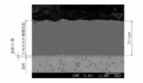
- 2 is a scanning electron micrograph showing a cross-section of the CrN / CrCN multilayer coating-coated piston ring of Example 1.
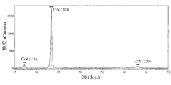
- FIG. 2 is a diagram showing an X-ray diffraction pattern of Example 1.
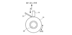
- FIG. It is the schematic of a rolling sliding fatigue testing machine.
- the piston ring of the present invention is a piston ring in which the outer peripheral sliding surface is coated with a CrN type hard coating of 10 to 60 ⁇ m, and the CrN type hard coating is alternately composed of a CrN layer and a CrCN layer in which C is dissolved in CrN.
- the laminated CrN / CrCN laminated film the laminated unit thickness of the CrN layer 1 layer and the CrCN layer 1 layer is 30 mm or more, the hardness of the CrN type hard film is Hv 1000 or more, the compressive residual stress is It is characterized by less than 1500 MPa.
- the CrN type chromium nitride may contain Cr 2 N type chromium nitride, but means that the main chromium nitride is CrN type.
- CrCN also has a crystal structure of CrN type, and C is a solid solution in a substitution type at a part of the N lattice position of CrN. Accordingly, since it is difficult to distinguish between CrN and CrCN peaks on the X-ray diffraction chart, the crystallite size of CrN / CrCN, which will be described later, is obtained from two overlapping peaks.
- the unit thickness of one CrN layer and one CrCN layer, that is, the sum of one CrN layer and one CrCN layer is 30 nm or more.
- the piston ring of the present invention for coating a hard film having a thickness of 10 to 60 ⁇ m is not preferable because the productivity is lowered.
- the stack unit thickness exceeds 100 nm, defects such as crystal grain boundaries and pores are likely to be introduced due to an increase in the growth rate of the film, and therefore the stack unit thickness is preferably 100 nm or less. More preferably, it is 80 nm or less.
- the hardness of the film is Hv 1000 or more. If the hardness of the film is less than Hv 1000, cracks perpendicular to the coated surface occur, which is not preferable.
- the residual stress of the film is a compressive stress of 1500 MPa or less.
- the compressive residual stress exceeds 1500 MPa, film peeling occurs and it cannot be used as a piston ring film.
- the hardness of the film is lowered when the compressive residual stress is lowered, it preferably has a residual compressive stress of at least 300 MPa or more.
- the carbon concentration in the CrCN layer is preferably 2 to 8% by mass.
- the carbon concentration of the CrN / CrCN multilayer coating is preferably 1 to 4% by mass when the thickness of the CrN layer and the CrCN layer is 1: 1.
- a laminated film in which different phases are laminated tends to propagate cracks along the interface because strain remains at the interface.
- CrN and CrCN basically have the same crystal structure and the lattice constant is very close, a highly consistent and strong interface is formed in the CrN / CrCN multilayer coating. If the thicknesses of the CrN layer and the CrCN layer are close to the crystallite size of the CrN layer and the CrCN layer, respectively, it can be regarded as a single crystal at least in the film thickness direction, and the rigidity is remarkably improved as compared with the polycrystal.
- the CrN layer and the CrCN layer are considered to be polycrystalline having a small tilt boundary in the direction parallel to the coating surface, and this configuration suppresses the propagation of cracks both at the interface of the laminated film and within the layer.
- the thickness of the laminated unit consisting of one CrN layer and one CrCN layer is preferably in the range of 2 to 6 times the crystallite size of CrN / CrCN, more preferably in the range of 2 to 4 times. .
- the thickness ratio of the CrN layer and the CrCN layer is not particularly limited, but is preferably in the range of 3: 7 to 7: 3 in consideration of the function of the CrN layer as a stress relaxation layer.
- the growth orientation of the stacked CrN layer and CrCN layer varies depending on the film formation conditions. Although this is not particularly limited, the CrN / CrCN laminated film preferably has the maximum diffraction intensity on the CrN (200) plane.
- the outermost sliding surface has a composite structure composed of CrN and CrCN. Even if the CrN / CrCN multilayer coating is formed parallel to a completely flat substrate surface, if the outer peripheral sliding surface is ground at an angle to the substrate surface, the outermost surface is a composite structure consisting of CrN and CrCN. It becomes. In the barrel face sliding surface preferably used in the pressure ring, since the outermost surface is not parallel to the substrate surface, a composite structure consisting essentially of CrN and CrCN is obtained. Moreover, as shown in FIG.
- a CrN (3) / CrCN (2) laminated film is formed on the substrate surface (1) on which the irregularities are formed, the laminated film is also formed in a wave shape, and the outer peripheral sliding surface is flat.
- a composite structure composed of CrN (3) and CrCN (2) is obtained on the outermost surface.
- the composite structure consisting of CrN (3) and CrCN (2) appearing on the outermost surface depends on the stacking thickness, the angle between the stacking surface and the polishing surface, the wavelength of the wavy stacked film, etc., but includes a contoured structure It is preferable.
- the average width of the phase showing the contoured structure is preferably 1 ⁇ m or less, and more preferably 0.4 ⁇ m or less.
- a metal layer for improving the adhesion may be formed between the laminated film and the substrate.
- the manufacturing method of the piston ring of the present invention is a manufacturing method of a piston ring in which the outer peripheral sliding surface is coated with 10-60 ⁇ m of CrN type hard coating, and the surface roughness of the outer peripheral surface of the base material of the piston ring is defined as Rzjis82.
- the above-mentioned CrN / CrCN multilayer coating is polished. It is characterized by processing.
- the surface roughness adjustment of the piston ring base material surface such as shot blasting so that the adhesion of the laminated film to the base material is ensured and the outermost surface of the outer peripheral sliding surface is a composite structure consisting of CrN and CrCN
- the surface roughness is adjusted to 0.5-3 ⁇ m.
- the polishing process after forming the CrN / CrCN laminated film by arc ion plating includes lapping and grinding with a grindstone, and plunge polishing is preferable if the purpose of forming the outer peripheral shape is included.
- the CrN / CrCN multilayer coating is formed using an arc ion plating apparatus having a schematic diagram (plan view from above) as shown in FIG.
- the object to be treated (16) (with piston rings stacked) is set in a vacuum vessel (10) having an inlet (11) and an outlet (12) for process gas, and the metal of the evaporation source.
- Cr cathodes (targets) (13, 14) are arranged at positions facing each other with the rotary table (15) in between.
- the workpiece (16) itself also rotates on the rotary table (15).
- the evaporation sources (13, 14) are connected to an anode (not shown) of an arc power source, and the rotary table (15) is connected to a bias power source (not shown).
- a heater (17) is installed on the wall of the apparatus.
- a process gas nitrogen (N 2 )
- N 2 nitrogen
- argon (Ar) gas to the nitrogen (N 2 ) gas and hydrocarbon (for example, CH 4 ) gas as the process gas.
- Ar argon
- N 2 nitrogen
- hydrocarbon for example, CH 4
- high ionization rate of metallic Cr can be achieved by high energy density.
- the vapor pressure of metal Cr is particularly high at the melting point, a high film formation speed can be obtained, and the film formation of 10 to 60 ⁇ m required for the piston ring is industrially possible.
- the CrN / CrCN multilayer coating can be formed by evaporating and ionizing Cr by discharge at a metal Cr cathode and switching the process gas.
- the process gas may be controlled by pressure, but is preferably controlled by flow rate in order to stabilize quickly.
- the process gas is preferably switched while maintaining the arc discharge of the metal Cr cathode.
- the composition of chromium nitride is determined by the amount of Cr evaporated from the metal Cr cathode and the partial pressure of nitrogen gas. Therefore, in the present invention, the arc current of the evaporation source and the nitrogen gas content are mainly composed of CrN type chromium nitride. Adjust pressure. Of course, the carbon concentration of the CrCN layer is adjusted by the partial pressure of the hydrocarbon gas. The thicknesses of the CrN layer and the CrCN layer are basically controlled by the formation time of each layer.
- the thickness of the CrN layer and the CrCN layer can be measured by direct observation using FE-SEM (Field-Emission--Scanning-Electron-Microscope) etc., but the unit thickness of the sum of the CrN layer and the CrCN layer is It is a value obtained by dividing the film thickness by the number of repeated lamination units, or a value obtained by multiplying the film formation rate ( ⁇ m / min) by the film formation time of one CrN layer and one CrCN layer. Since the deposition rate increases as the arc current increases, the unit thickness of the stack decreases as the arc current is decreased or the formation time of each layer is shortened.
- the crystal structure of the film formed by arc ion plating can be generally adjusted by the furnace pressure and bias voltage.
- the furnace pressure is increased and the bias voltage is lowered, columnar crystals are formed.
- the furnace pressure is lowered, It is said that a granular structure can be obtained by increasing the bias voltage.
- a bias voltage is increased, a columnar crystal is formed.
- the ion plating film formation environment is very complex.For example, if the equipment is changed, there is no guarantee that the same structure can be obtained even if the same arc current, furnace pressure and bias voltage are selected. is there.
- the structure in the furnace (arrangement of the object to be processed and the evaporation source, etc.) has a relatively large influence, and the film formation conditions are Must be set for each device.
- Example 1 A piston ring with a nominal diameter (d) of 96 mm, thickness (a1) of 3.8 mm, width (h1) of 2.5 mm, and a barrel face shape on the outer peripheral surface was prepared from SWOSC-V equivalent wire. 50 piston rings were stacked, and the outer peripheral surface was adjusted to a surface roughness of 1.9 ⁇ m by shot blasting with Rzjis82 and set in an arc ion plating apparatus (AIP-S40 made by Kobe Steel). As the evaporation source target, 99.9% pure metallic chromium was used.
- the inside of the apparatus was evacuated to 1.0 ⁇ 10 ⁇ 2 Pa, Ar gas was introduced to 1.0 Pa, and a bias voltage of ⁇ 900 V was applied to clean the outer peripheral surface of the piston ring as a base material by bombardment treatment. Ar gas having a purity of 99.99% was used. A metal Cr layer was formed to improve adhesion by performing ion plating for 10 minutes at an arc current of 150A, bias voltage of 0 V and table rotation speed of 3 rpm.
- Thickness measurement was performed by measuring the length from the substrate surface to the surface of the coating on a mirror-polished piston ring cross section perpendicular to the coated surface, using a scanning electron microscope (SEM) photograph. Film thickness.
- FIG. 3 shows an SEM photograph.
- the film thickness of the laminated film excluding the metallic Cr intermediate layer of Example 1 was 23.3 ⁇ m.
- the film (dark gray) contained a small amount of metallic Cr particles (obvious color).
- the lamination unit thickness one CrN layer + one CrCN layer was calculated as 0.0583 ⁇ m (58.3 nm) from the above-mentioned film thickness of 23.3 ⁇ m and the number of repetitions of the lamination unit (400 times).
- Carbon concentration measurement The carbon concentration in the film was determined by quantitative analysis of the film cross-section with EPMA (JEOL, JXA-8600S). The carbon concentration of Example 1 was 2.7% by mass.
- Hardness measurement was performed on a surface parallel to the mirror-polished coated surface using a micro Vickers hardness tester with a test force of 0.9807 N.
- the hardness of the CrN / CrCN multilayer coating of Example 1 was Hv 1266.
- FIG. 4 shows the X-ray diffraction pattern obtained in Example 1, showing the maximum peak intensity on the CrN (200) plane, followed by the CrN (111) plane and the CrN (220) plane, followed by diffraction peaks. .
- the CrN phase and the CrCN phase could not be distinguished.
- the crystallite size D hkl was calculated on the CrN (200) plane using the following Scherrer equation.
- Test piece CrC / CrCN multilayer coating coated piston ring cut piece, Load: 98-196 N, sine curve 50 Hz, Counterpart material (drum): 80 mm diameter SUJ2 material, Sliding speed: Forward / reverse rotation pattern operation ( ⁇ 2 m / sec), Hold for 10 seconds at speed ⁇ 2 m / s, acceleration 0.08 m / s 2 , Lubricant: pure water, 4 cc / min, Temperature: drum surface temperature 80 °C, Test time: 1 hour. In addition, the test result was determined by the presence or absence of film removal. As a result of the rolling sliding fatigue test of Example 1, there was no film falling off.
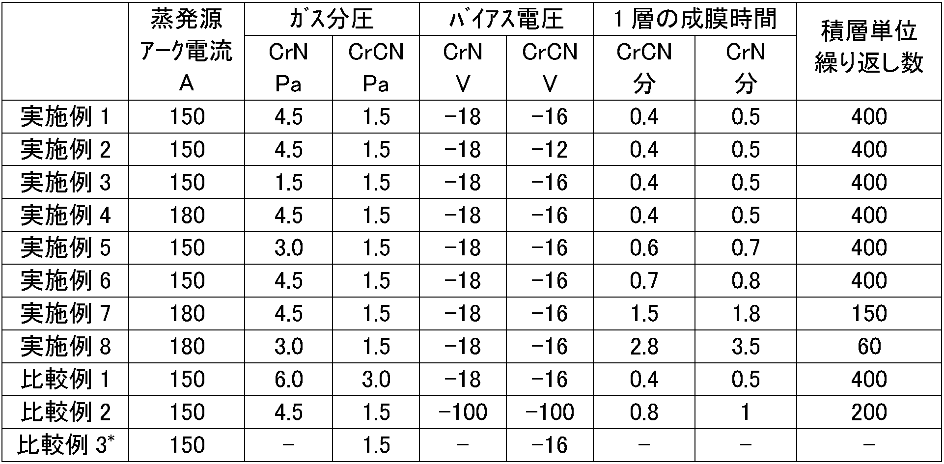
- Examples 2 to 8 and Comparative Examples 1 to 3 For Examples 2 to 8 and Comparative Examples 1 to 3, ion plating treatment was performed under the film forming conditions shown in Table 1. Table 1 also shows the film forming conditions of Example 1. In Example 2, the bias voltage during CrCN formation was lower than that in Example 1, and in Example 3, the gas partial pressure during CrN formation was lower than that in Example 1. In Example 4, the arc current of the evaporation source is increased to 180 A, and in Example 5, the gas partial pressure during CrN formation is intermediate between Example 1 and Example 3, and one layer of CrN layer and CrCN layer is formed. The film formation time was slightly increased.
- Example 6 the deposition time of the CrN layer and the CrCN layer was about 1.6 times that of Example 1, and in Examples 7 and 8, the arc current of the evaporation source was set higher than that of Example 1 in order to change the stack unit thickness.
- the film formation time of CrN layer and CrCN layer was increased.
- Comparative Example 1 increases the gas partial pressure during film formation
- Comparative Example 2 increases the bias voltage
- Comparative Example 3 is formed as a CrCN single phase instead of a laminated film. Filmed.
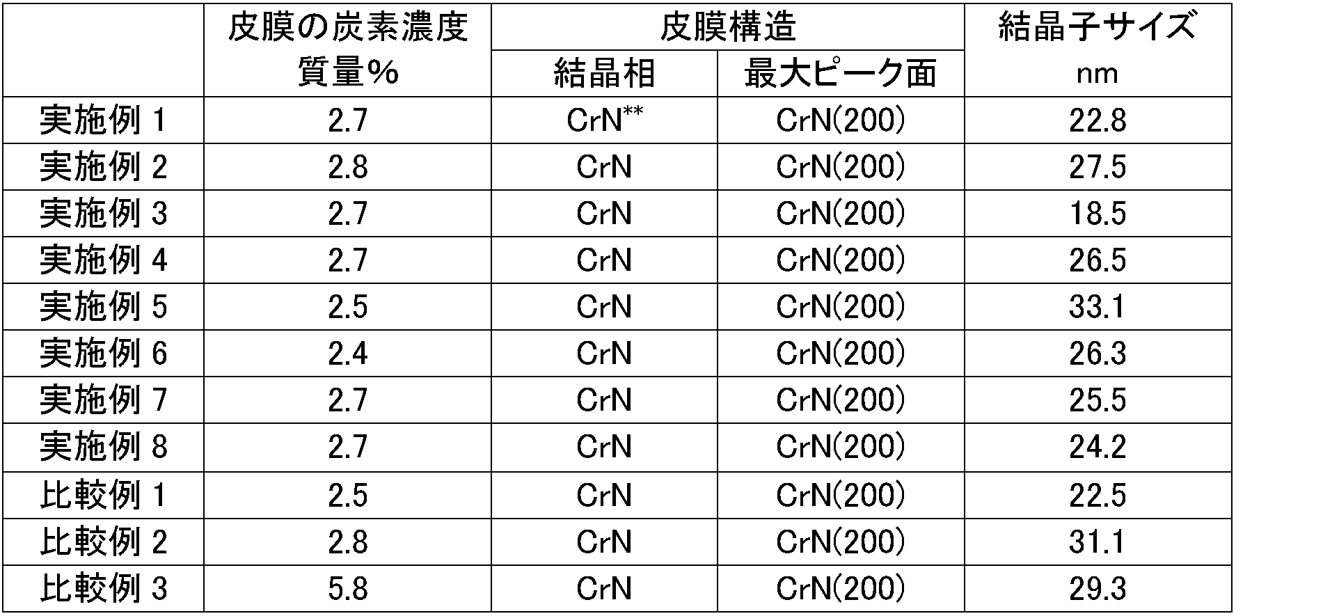
- Table 2 shows the results of carbon concentration measurement and X-ray diffraction measurement in the film by EPMA.
- the carbon concentration of the film was 2.4 to 2.8% by mass except for Comparative Example 3.
- the carbon concentration of Comparative Example 3 in which the entire film is made of CrCN was 5.8% by mass.
- the coating was composed of CrN type chromium nitride, and the maximum peak was obtained on the CrN (200) plane.
- the CrCN layer was indistinguishable from the CrN layer type on the X-ray diffraction chart.
- the crystallite size was 18.5 to 33.1 nm. Note that the ratio of the thickness of the CrN layer to the CrCN layer in the CrN / CrCN laminated film was approximately 1: 1.
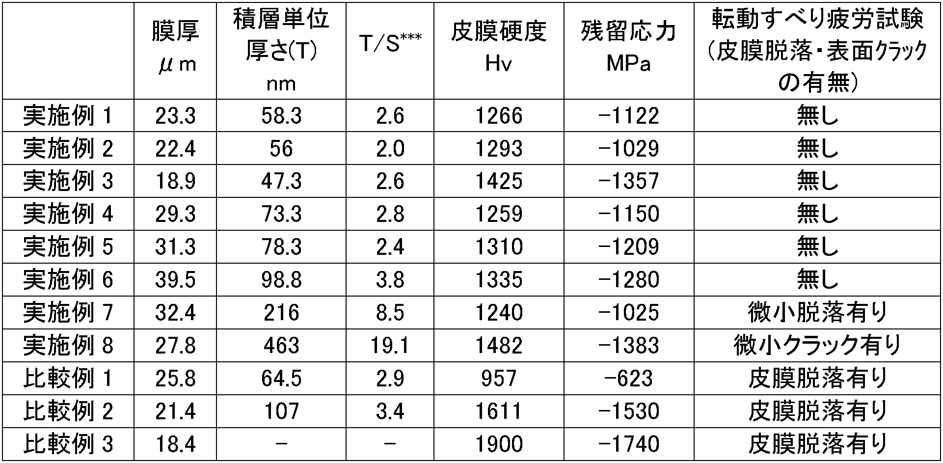
- Table 3 shows the results of film thickness, film hardness, compressive residual stress, and rolling sliding fatigue test.
- the film thickness was 18.9 to 39.5 ⁇ m.
- the stack unit thickness is 47.3 to 463 nm, and when the ratio to the crystallite size of the CrN type hard coating shown in Table 2 obtained from X-ray diffraction measurement is taken. 2.0 to 19.1.
- the film hardness was Hv 1240 to 1482 in Examples 1 to 8, and the residual stress was -1025 to -1383 (MPa (a negative symbol indicates compression).
- Comparative Example 1 The film hardness of Comparative Example 1 was 957, the residual stress was -623 MPa, the film hardness of Comparative Example 2 was 1611, the residual stress was -1530 MPa, the film hardness of Comparative Example 3 was 1900, and the residual stress was -1740 MPa. .
- Example 7 had minute dropouts and Example 8 had minute cracks, but Examples 1 to 6 had no film dropout or surface cracks.
- film loss was observed in Comparative Examples 1 to 3.
Landscapes
- Chemical & Material Sciences (AREA)
- Engineering & Computer Science (AREA)
- Mechanical Engineering (AREA)
- Metallurgy (AREA)
- Materials Engineering (AREA)
- Chemical Kinetics & Catalysis (AREA)
- Organic Chemistry (AREA)
- Inorganic Chemistry (AREA)
- General Engineering & Computer Science (AREA)
- Ceramic Engineering (AREA)
- Physical Vapour Deposition (AREA)
- Pistons, Piston Rings, And Cylinders (AREA)
- Grinding Of Cylindrical And Plane Surfaces (AREA)
Abstract
【課題】 エンジンの機械的及び熱的負荷の高い環境で使用することが可能な、耐スカッフ性、耐摩耗性、さらには耐皮膜剥離性に優れた積層硬質皮膜を被覆したピストンリングを提供するため、CrN層とCrNにCを固溶したCrCN層を交互に積層したCrN/CrCN積層皮膜を含み、CrN層1層とCrCN層1層からなる積層単位厚さが30 nm以上、硬度がHv 1000以上、圧縮残留応力が1500 MPa以下のCrN型硬質皮膜を、イオンプレーティングによりピストンリングの外周摺動面に10~60μm被覆する。
Description
本発明は、自動車エンジン用ピストンリングに関し、特に、耐スカッフ性、耐摩耗性、さらに耐皮膜剥離性に優れた積層硬質皮膜をイオンプレーティングにより被覆したピストンリングに関する。
近年、ピストンリングは、エンジンの高出力化や排気ガス規制対応に伴う燃焼温度の高温化や面圧負荷の増大、また、低粘度潤滑油の採用、バイオエタノール等の燃料の多様化、さらには高圧燃料噴射等により、その使用環境は年々過酷になってきている。耐スカッフ性及び耐摩耗性が最も優れるといわれているイオンプレーティングによる硬質窒化クロム(CrN)被覆ピストンリングでも、クラックや欠けの発生を含む皮膜剥離の問題により、十分な性能を発揮できない状況が散見されるようになってきた。従って、従来になく、耐スカッフ性、耐摩耗性、さらに耐皮膜剥離性に優れたピストンリングが強く求められている。
上記のイオンプレーティングによる窒化クロムは、一般的には、硬いが欠けやすいという課題があり、これまで、結晶方位、組織制御、空隙率(空孔率)制御、あるいは第三元素の添加、皮膜の積層化等、様々な改良がなされてきた。
窒化クロムへの第三元素の添加については、CrNの靱性を向上させるため、特開平6-265023は酸素(O)を、特開平6-300130は炭素(C)を固溶させることを教示している。さらに国際公開第2008/059791は、窒化クロム皮膜が皮膜表面に向かって柱状の形態を有し、クロムと窒素と炭素からなる主成分の合計に対する炭素濃度が4~8重量%で、ビッカース硬度が1600以上、破壊靱性値が3 MPa√m以上の耐摩耗性に優れ、欠けの発生しにくいCrCN皮膜を開示している。
また、皮膜の積層化については、例えば、ピストンリング外周皮膜表面のピッチング疲労に起因する欠け状剥離の問題を解決するため、特開平8-312779は、皮膜破断面のCrN結晶が基材表面から皮膜表面の方向に向かう柱状層と平滑状層を交互に積層させた皮膜、又は、空孔率0~0.5体積%の層と空孔率1.5~20体積%の層を交互に積層させた皮膜を開示している。さらに、特開2005-187859は、同様な観点で、例えば、CrSiNやTiSiNの複合窒化物皮膜について、柱状晶ができる高バイアス電圧条件と、柱状晶ができない低バイアス電圧条件を一定時間毎に交互に繰り返して、柱状晶の複合窒化物の硬質皮膜の中に、一定間隔毎に一定厚みの柱状晶ではない構造の該複合窒化物の応力緩和層を挟み込んで、内部応力を低減し、高い密着力をもった硬質厚膜皮膜を開示している。
上記の特開平8-312779及び特開2005-187859は、いずれも、同じ窒化物の範囲内で、異なる組織(柱状組織層/非柱状組織層、又は多孔質組織層/緻密質組織層)の窒化物層を積層したものであるが、特開2005-82822は、特開2005-187859でいう応力緩和層として金属層を積層する積層皮膜、すなわち、異なる組成を含む積層皮膜を開示している。しかし、金属層の存在が、応力緩和という観点では特開2005-187859の複合窒化物層より優れた効果をもたらすものの、耐スカッフ性という観点ではマイナスに作用してしまうという欠点も有していた。
特開2007-278314は、チタン、炭素及び窒素から構成される化合物層と、クロム、炭素及び窒素から構成される化合物層が、交互に積層された積層皮膜を有するピストンリングを開示している。そこでは、ディーゼルエンジンのトップリングに使用しても欠けを生じず、耐摩耗性にも優れた皮膜とするため、その性能に密接に関係する硬質皮膜の破壊靱性値と硬度について、破壊靱性値が約3 MPa√m以上、硬度がHv 1700以上となるように、炭素の固溶量や空孔率を決定している。
しかしながら、上述したような皮膜の積層化も、一部の非常に厳しい環境で使用されるピストンリングに対しては十分ではなく、硬質皮膜の疲労によるクラックや欠けの発生を含む皮膜剥離の問題を完全に解決できていないのが実情である。
本発明は、エンジンの機械的及び熱的負荷の高い環境で使用することが可能な、耐スカッフ性、耐摩耗性、さらには耐皮膜剥離性に優れた積層硬質皮膜をイオンプレーティングにより被覆したピストンリング及びその製造方法を提供することを課題とする。
本発明者らは、イオンプレーティングによりピストンリングに被覆した硬質皮膜に負荷される機械的応力及び熱応力に対し、破壊靱性及び硬度の改善に加え、成膜により導入された残留応力に注目して、鋭意研究した結果、CrNにCを固溶して破壊靱性と硬度を高めたCrCN層と、硬度が比較的低いCrN層とを積層することにより、さらには各層の厚さを各結晶子サイズに近い厚さに制御することにより、硬度や破壊靱性を改善し、残留応力を最適化した、耐スカッフ性、耐摩耗性及び耐皮膜剥離性に優れた積層硬質皮膜を被覆したピストンリングとすることができることに想到した。
すなわち、本発明のピストンリングは、外周摺動面にCrN型硬質皮膜が10~60μm被覆されたピストンリングであって、前記CrN型硬質皮膜がCrN層とCrNにCを固溶したCrCN層の交互に積層したCrN/CrCN積層皮膜を含み、前記CrN層1層と前記CrCN層1層からなる積層単位厚さが30 nm以上であり、前記CrN型硬質皮膜の硬度がHv 1000以上、圧縮残留応力が1500 MPa以下であることを特徴とする。前記CrCN層の炭素濃度は2~8質量%であることが好ましく、よって、CrN層とCrCN層をほぼ1:1に積層した前記CrN型硬質皮膜の炭素濃度は1~4質量%であることが好ましい。
前記CrN層と前記CrCN層について剛性が高く強度的に強い皮膜とするためには、できるだけ結晶性の高い皮膜とすることが好ましく、そのためには、前記CrN型硬質皮膜の前記積層単位厚さが、30~100 nmであって、前記CrN型硬質皮膜のX線回折データから得られる結晶子サイズの2~6倍の範囲内にあることが好ましい。
また、前記CrN型硬質皮膜の被覆面のX線回折強度が、CrN(200)面で最大となることが好ましい。
さらに、前記外周摺動面の最表面がCrN相とCrNにCを固溶したCrCN相からなる複合組織を有することが好ましい。
また、外周摺動面にCrN型硬質皮膜が10~60 μm被覆された本発明のピストンリングの製造方法は、前記ピストンリングの基材外周表面の表面粗さをRzjis82で0.5~3μmに調整し、アークイオンプレーティングによりCrN層とCrNにCを固溶したCrCN層の形成を交互に繰り返してCrN/CrCN積層皮膜を形成した後、前記CrN/CrCN積層皮膜を研磨加工することを特徴とする。
前記CrN層の形成にはプロセスガスとして窒素ガスを用い、前記CrCN層の形成にはプロセスガスとして窒素ガス、炭化水素ガス及びアルゴンガスを用いることが好ましい。また、前記プロセスガスは流量により制御されるのが好ましく、さらに、前記CrN層を形成する際のプロセスガスと前記CrCN層を形成する際のプロセスガスの切り替えを、金属Cr陰極のアーク放電を維持したまま行うことが好ましい。
本発明の耐スカッフ性、耐摩耗性及び耐皮膜剥離性に優れたCrN/CrCN積層硬質皮膜被覆ピストンリングは、相対的に硬度の低いCrN層と、破壊靱性と硬度を高めたCrCN層とを交互に積層しているので、CrN層が応力緩和層として機能し、クラックの発生及び/又は伝播を抑え、高い耐皮膜剥離性を示すことができる。また、クラックの伝播という観点では、ヤング率と硬度の高いCrCN層を積層することに加え、CrN層とCrCN層の積層単位厚さを各結晶の結晶子サイズの和に近い厚さとすることによって、高い結晶性、すなわち、高い剛性のCrN層及びCrCN層とし、クラックの伝播に高い耐性を示す皮膜とすることができる。このようにCrN層とCrCN層を積層した硬質皮膜を被覆したピストンリングは、結果的に、優れた耐スカッフ性、耐摩耗性、耐皮膜剥離性を発揮するバランスのとれた圧縮残留応力を有し、それにより多様化した厳しい環境下でも使用することを可能とする。
本発明のピストンリングは、外周摺動面にCrN型硬質皮膜が10~60μm被覆されたピストンリングであって、前記CrN型硬質皮膜がCrN層とCrNにCを固溶したCrCN層の交互に積層したCrN/CrCN積層皮膜を含み、前記CrN層1層と前記CrCN層1層からなる積層単位厚さが30 nm以上であり、前記CrN型硬質皮膜の硬度がHv 1000以上、圧縮残留応力が1500 MPa以下であることを特徴とする。すなわち、耐スカッフ性、耐摩耗性及び耐皮膜剥離性に優れたピストンリングを得るためにCrN/CrCN積層皮膜の積層構造及びその形成方法に特徴を有する。
CrN型の窒化クロムとは、Cr2N型の窒化クロムを含んでもよいが、主たる窒化クロムがCrN型であることを意味する。CrCNも結晶構造はCrN型であり、CrNのNの格子位置の一部にCが置換型に固溶したものである。従って、X線回折チャート上では、CrNとCrCNのピークを区別することは難しいので、後述するCrN/CrCNの結晶子サイズは、重なった二つのピークから求めたものとする。また、CrN層1層とCrCN層1層からなる積層単位厚さ、すなわち、CrN層1層の厚さとCrCN層1層の厚さの和は、30 nm以上とする。積層単位厚さが30 nm未満では、皮膜の成長速度を抑えざるを得ないため、10~60μmの硬質皮膜を被覆する本発明のピストンリングとしては製造性が低下し好ましくない。一方、積層単位厚さが100 nmを超えると、皮膜の成長速度の増加に起因して結晶粒界や気孔などの欠陥が導入されやすくなるため、積層単位厚さは100 nm以下が好ましい。より好ましくは80 nm以下とする。さらに、皮膜の硬度はHv 1000以上とする。皮膜の硬度がHv 1000未満では、被覆面に垂直なクラックが発生して好ましくない。高硬度側を考慮すると、好ましくはHv 1450以下とする。皮膜の残留応力は圧縮応力で1500 MPa以下とする。圧縮残留応力が1500 MPaを超えると、皮膜剥離が発生しピストンリングの皮膜としては使用できなくなる。逆に圧縮残留応力が低くなると皮膜の硬度も低下するため、少なくとも300 MPa以上の残留圧縮応力を有していることが好ましい。
CrCN層のCはCrNの一部のNの格子位置に置換型に固溶し、Cr及びN(又はC)の両方のイオン半径を歪ませ格子歪みを増加することによって硬度を増加する。一方、高硬度を維持しつつ結晶成長中に蓄積される内部エネルギーを低減して、マクロな残留応力を低く抑え、破壊靱性を高めているともいわれている。それらの特性を得るためには、CrCN層中の炭素濃度は2~8質量%が好ましい。CrN/CrCN積層皮膜の炭素濃度としては、CrN層とCrCN層の厚さが1:1とすれば1~4質量%が好ましい。
アークイオンプレーティングによりピストンリングに被覆した硬質皮膜にクラック又は欠けが発生する場合、皮膜表面又は内部に存在する欠陥を起点とし、摺動によって発生する皮膜最表面の引張応力又は皮膜内部の剪断応力によりクラックが伝播し、皮膜の欠けや脱落あるいは皮膜剥離という形態で破壊に至る。CrN/CrCN積層皮膜とすることにより得られたバランスのとれた皮膜の圧縮残留応力は、摩擦による引張応力や剪断応力を低減し、クラックの伝播を抑制する。また、積層した剛性(ヤング率及び硬度)の高いCrCN層は、被覆面に垂直なクラックを止める効果を有する。
さらに、異なる相を積層した積層皮膜は、一般には、その界面に歪みが残るため界面に沿ってクラックが伝播しやすい。しかし、CrNとCrCNは、基本的に同じ結晶構造を有し、格子常数も非常に近いため、CrN/CrCN積層皮膜では整合性の高い、強い界面が形成される。CrN層及びCrCN層の厚さが、それぞれCrN層及びCrCN層の結晶子サイズに近づけば、少なくとも膜厚方向には単結晶と見なすことができ、多結晶に比べ、剛性が格段に向上する。但し、前述したように、X線回折の測定ではCrN相とCrCN相のピークを区別できないため、両相とも同水準の結晶子サイズをもつものとして求めている。CrN層及びCrCN層は、被覆面に平行な方向には小傾角境界をもつ多結晶と考えられ、この構成は、積層皮膜の界面、層内の両方でのクラックの伝播を抑制する。CrN層1層とCrCN層1層からなる積層単位厚さは、CrN/CrCNの結晶子サイズの2~6倍の範囲内にあることが好ましく、2~4倍の範囲内であればより好ましい。
CrN層及びCrCN層の厚さの比率は、特に限定するものではないが、CrN層の応力緩和層としての機能を考慮すると、3:7~7:3の範囲とすることが好ましい。
積層したCrN層とCrCN層の成長方位は、成膜条件によって異なる。これも特に限定するものではないが、CrN/CrCN積層膜はCrN(200)面で最大の回折強度となることが好ましい。
また、本発明のピストンリングは、その外周摺動面の最表面がCrNとCrCNからなる複合組織を有することが好ましい。CrN/CrCN積層皮膜は、完全な平面の基材面に平行に形成したとしても、外周摺動面を基材面に角度を付けて研磨すれば、その最表面はCrNとCrCNからなる複合組織となる。圧力リングで好ましく使用されるバレルフェイス摺動面では、最表面が基材面に平行でないため、基本的にCrNとCrCNからなる複合組織が得られる。また、図1に示すように、凹凸を形成した基材面(1)にCrN(3)/CrCN(2)積層皮膜を形成すれば、積層皮膜も波状に形成され、外周摺動面を平面に研磨すれば、CrN(3)とCrCN(2)からなる複合組織がその最表面に得られる。一般に、基材面に凹凸を形成し、その上にCrN(3)/CrCN(2)積層皮膜を形成することがより好ましい。最表面に現れるCrN(3)とCrCN(2)からなる複合組織は、積層厚さ、積層面と研磨面との角度、波状積層膜の波長、等に依存するが、等高線状の組織を含むことが好ましい。等高線状の組織を示す相の幅は平均で1μm以下であることが好ましく、0.4μm以下であることがより好ましい。
なお、積層皮膜と基材との間に、その密着性を改善するための金属層を形成してもよい。
本発明のピストンリングの製造方法は、外周摺動面にCrN型硬質皮膜が10~60 μm被覆されたピストンリングの製造方法であって、前記ピストンリングの基材外周表面の表面粗さをRzjis82で0.5~3μmに調整し、アークイオンプレーティングによりCrN層とCrNにCを固溶したCrCN層の形成を交互に繰り返してCrN/CrCN積層皮膜を形成した後、前記CrN/CrCN積層皮膜を研磨加工することを特徴とする。ピストンリングの基材外周表面は、積層皮膜の基材への密着性確保と、外周摺動面の最表面がCrNとCrCNからなる複合組織となるよう、ショットブラスト処理のような表面粗さ調整手段により、Rzjis82で0.5~3μmの表面粗さに調整する。また、アークイオンプレーティングによりCrN/CrCN積層皮膜を形成した後の研磨加工は、ラップ研磨や砥石による研削加工を含み、外周形状形成の目的も含めればプランジ研磨が好ましい。
本発明では、CrN/CrCN積層皮膜は、図2に示すような概略図(上から見た平面図)のアークイオンプレーティング装置を用いて形成する。この装置では、プロセスガスの導入口(11)と排出口(12)を有する真空容器(10)中に、被処理物(16)(ピストンリングを重ねたもの)をセットし、蒸発源の金属Cr陰極(ターゲット)(13,14)を、回転テーブル(15)を挟んで対向した位置に配置している。被処理物(16)自体も回転テーブル(15)上で自転する。蒸発源(13,14)はアーク電源の陽極(図示しない)に接続され、回転テーブル(15)はバイアス電源(図示しない)に接続されている。なお、ヒーター(17)が装置の壁面に設置されている。アークイオンプレーティング法は、CrN層を形成する場合、真空容器(10)中にプロセスガス(窒素(N2))を導入し、蒸発源の金属Cr陰極表面にアークを発生させ、金属Crを瞬時に溶解、窒素プラズマ中でイオン化し、被処理物(16)に印加した負のバイアス電圧によってクロムイオンあるいは窒素プラズマと反応したCrNとして被覆面に引き込むことで、CrN層として堆積する方法である。CrCN層を形成する場合は、プロセスガスとして窒素(N2)ガスと炭化水素(例えば、CH4)ガスに、さらにアルゴン(Ar)ガスを加えることが好ましい。アークイオンプレーティングでは、高いエネルギー密度により、金属Crの高イオン化率を達成できる。また、金属Crは融点における蒸気圧が特に高いため、高い成膜速度が得られ、ピストンリングに要求される10~60μmの成膜が工業的に可能となる。
CrN/CrCN積層皮膜は、金属Cr陰極における放電によりCrを蒸発、イオン化させ、プロセスガスを切り替えることによって形成することができる。プロセスガスは、圧力により制御してもよいが、速く安定させるためには、流量により制御することが好ましい。また、プロセスガスの切り替えは、金属Cr陰極のアーク放電を維持したまま行うことが好ましい。CrN層とCrCN層を明確に区別できる積層皮膜を形成する上では、アーク放電を止めてプロセスガスの流量を安定させた後に再着火することが好ましいが、再着火の際にストライカーロッドに堆積した皮膜が飛散して一種のピット不良が増加するというデメリットがあるからである。さらに、窒化クロムの組成は、金属Cr陰極からのCrの蒸発量と窒素ガスの分圧によって決まるので、本発明では、CrN型窒化クロムが主体となるように蒸発源のアーク電流と窒素ガス分圧を調整する。CrCN層の炭素濃度は、もちろん炭化水素ガスの分圧によって調整する。CrN層とCrCN層の各層の厚さは、基本的に各層の形成時間により制御する。CrN層とCrCN層の厚さは、FE-SEM(Field Emission - Scanning Electron Microscope)等を利用した直接観察により測定できるが、CrN層1層とCrCN層1層の和の積層単位厚さは、膜厚を積層単位繰り返し数で除した値、又は、成膜速度(μm/min)にCrN層1層とCrCN層1層の成膜時間を乗じた値となる。成膜速度はアーク電流を上げると増加するので、アーク電流を下げるか又は各層の形成時間を短くすれば積層単位厚さは小さくなる。
アークイオンプレーティングによって形成した皮膜の結晶組織は、一般に、炉内圧とバイアス電圧により調整可能であり、炉内圧を高くし、バイアス電圧を低くすると柱状晶になり、逆に炉内圧を低くし、バイアス電圧を高くすると粒状組織が得られると言われている。しかし、特開2005-187859のようにバイアス電圧を高くすると柱状晶になるという教示もあり、一概にそういえないのが現実である。イオンプレーティングの成膜環境は非常に複雑であり、例えば、装置を変更すれば、同じアーク電流、炉内圧、バイアス電圧を選択したとしても、同じ組織が得られる保証が全くないのが実情である。もちろん、基材の材質、結晶構造、温度、表面状態等にも関係するが、炉内の構造(被処理物と蒸発源の配置等)も比較的大きな影響を及ぼしており、成膜条件は装置毎に設定されなければならない。
実施例1
SWOSC-V相当材の線材から呼称径(d)96 mm、厚さ(a1)3.8 mm、幅(h1)2.5 mmの矩形断面で、外周面をバレルフェイス形状としたピストンリングを作製し、このピストンリングを50本重ね、外周面をショットブラストによりRzjis82で1.9μmの表面粗さに調整し、アークイオンプレーティング装置(神戸製鋼製AIP-S40)内にセットした。蒸発源のターゲットとしては純度99.9 %の金属クロムを使用した。装置内を1.0×10⁻² Paまで真空引きした後、Arガスを1.0 Paまで導入、-900 Vのバイアス電圧を印加してボンバードメント処理により基材となるピストンリング外周面を清浄化した。Arガスは99.99 %の純度のものを用いた。金属クロム陰極のアーク電流を150A、バイアス電圧 0 V、テーブル回転速度3 rpmで、10分間イオンプレーティング処理を行うことにより、密着性改善を目的とした金属Cr層を成膜し、その後、純度99.999%のN2ガスを4.5 Paまで導入してバイアス電圧-18VでCrN層の成膜を24秒間行った後、N2ガスを0.87 Pa、上記Arガスを0.09 Pa、純度99.9%のCH4ガスを0.54 Paとなるように流量調節してバイアス電圧-16VでCrCN層の成膜を30秒間行った。このCrN層とCrCN層の形成を400回繰り返して、CrN/CrCN積層皮膜を成膜した。得られたCrN/CrCN積層皮膜被覆ピストンリングは、次の各種測定に供した。
SWOSC-V相当材の線材から呼称径(d)96 mm、厚さ(a1)3.8 mm、幅(h1)2.5 mmの矩形断面で、外周面をバレルフェイス形状としたピストンリングを作製し、このピストンリングを50本重ね、外周面をショットブラストによりRzjis82で1.9μmの表面粗さに調整し、アークイオンプレーティング装置(神戸製鋼製AIP-S40)内にセットした。蒸発源のターゲットとしては純度99.9 %の金属クロムを使用した。装置内を1.0×10⁻² Paまで真空引きした後、Arガスを1.0 Paまで導入、-900 Vのバイアス電圧を印加してボンバードメント処理により基材となるピストンリング外周面を清浄化した。Arガスは99.99 %の純度のものを用いた。金属クロム陰極のアーク電流を150A、バイアス電圧 0 V、テーブル回転速度3 rpmで、10分間イオンプレーティング処理を行うことにより、密着性改善を目的とした金属Cr層を成膜し、その後、純度99.999%のN2ガスを4.5 Paまで導入してバイアス電圧-18VでCrN層の成膜を24秒間行った後、N2ガスを0.87 Pa、上記Arガスを0.09 Pa、純度99.9%のCH4ガスを0.54 Paとなるように流量調節してバイアス電圧-16VでCrCN層の成膜を30秒間行った。このCrN層とCrCN層の形成を400回繰り返して、CrN/CrCN積層皮膜を成膜した。得られたCrN/CrCN積層皮膜被覆ピストンリングは、次の各種測定に供した。
[1] 膜厚測定
膜厚測定は、被覆面に垂直な鏡面研磨したピストンリング断面について、走査電子顕微鏡(SEM)による写真から、皮膜の基材面から表面までの長さを測定し、試料の膜厚とした。図3にSEM写真を示す。実施例1の金属Cr中間層を除いた積層皮膜の膜厚は23.3μmであった。また、皮膜は(暗灰色)は、僅かではあるが金属Crのパーティクル(明白色)を含んでいた。積層単位厚さ(CrN層1層+CrCN層1層)は、上記膜厚23.3μmと積層単位の繰り返し数(400回)から0.0583μm(58.3 nm)と算出された。
膜厚測定は、被覆面に垂直な鏡面研磨したピストンリング断面について、走査電子顕微鏡(SEM)による写真から、皮膜の基材面から表面までの長さを測定し、試料の膜厚とした。図3にSEM写真を示す。実施例1の金属Cr中間層を除いた積層皮膜の膜厚は23.3μmであった。また、皮膜は(暗灰色)は、僅かではあるが金属Crのパーティクル(明白色)を含んでいた。積層単位厚さ(CrN層1層+CrCN層1層)は、上記膜厚23.3μmと積層単位の繰り返し数(400回)から0.0583μm(58.3 nm)と算出された。
[2] 炭素濃度測定
皮膜中の炭素濃度は、皮膜断面をEPMA(JEOL, JXA-8600S)にて定量分析を実施して求めた。実施例1の炭素濃度は2.7質量%であった。
皮膜中の炭素濃度は、皮膜断面をEPMA(JEOL, JXA-8600S)にて定量分析を実施して求めた。実施例1の炭素濃度は2.7質量%であった。
[3] 硬度測定
硬度測定は、鏡面研磨した被覆面に平行な表面について、マイクロビッカース硬度計を使用し、試験力0.9807 Nで行った。実施例1のCrN/CrCN積層皮膜の硬度はHv 1266であった。
硬度測定は、鏡面研磨した被覆面に平行な表面について、マイクロビッカース硬度計を使用し、試験力0.9807 Nで行った。実施例1のCrN/CrCN積層皮膜の硬度はHv 1266であった。
[4] 残留応力測定
皮膜の残留応力σは、次のStoneyの式により算出した。
σ=-{Es(1-νs)hs 2}/6hfΔR ………………………………………(1)
ここで、Esは基材のヤング率(N/mm2)、νsは基材のポアソン比、hsは基材の厚さ、hfは皮膜厚さ、ΔRは曲率変化量である。なお、Es及びνsは、それぞれ、200,000 N/mm2及び0.3とした。実施例1の残留応力は-1,122 MPa(圧縮で1,122 MPa)であった。
皮膜の残留応力σは、次のStoneyの式により算出した。
σ=-{Es(1-νs)hs 2}/6hfΔR ………………………………………(1)
ここで、Esは基材のヤング率(N/mm2)、νsは基材のポアソン比、hsは基材の厚さ、hfは皮膜厚さ、ΔRは曲率変化量である。なお、Es及びνsは、それぞれ、200,000 N/mm2及び0.3とした。実施例1の残留応力は-1,122 MPa(圧縮で1,122 MPa)であった。
[5] X線回折測定
X線回折強度は、鏡面研磨した被覆面に平行な表面について、管電圧40 kV、管電流30mAのCu-Kα線を使用して2θ=35~70°の範囲で測定した。図4に実施例1で得られたX線回折パターンを示すが、CrN(200)面で最大ピーク強度を示し、続いてCrN(111)面、CrN(220)面と続く回折ピークを示した。CrN相とCrCN相を区別することはできなかった。また、CrN(200)面にて、次のScherrerの式を用いて結晶子サイズDhklを算出した。
Dhkl=Kλ/βcosθ……………………………………………………(2)
ここで、KはScherrerの定数で0.94、λはX線の波長(Cu:1.5406Å)、βは半値全幅(FWHM)、θはBragg角である。実施例1のCrN型硬質皮膜の結晶子サイズは22.8 nmであった。膜厚から計算した積層単位厚さ58.3 nmは、窒化クロム結晶子サイズの2.6倍であった。
X線回折強度は、鏡面研磨した被覆面に平行な表面について、管電圧40 kV、管電流30mAのCu-Kα線を使用して2θ=35~70°の範囲で測定した。図4に実施例1で得られたX線回折パターンを示すが、CrN(200)面で最大ピーク強度を示し、続いてCrN(111)面、CrN(220)面と続く回折ピークを示した。CrN相とCrCN相を区別することはできなかった。また、CrN(200)面にて、次のScherrerの式を用いて結晶子サイズDhklを算出した。
Dhkl=Kλ/βcosθ……………………………………………………(2)
ここで、KはScherrerの定数で0.94、λはX線の波長(Cu:1.5406Å)、βは半値全幅(FWHM)、θはBragg角である。実施例1のCrN型硬質皮膜の結晶子サイズは22.8 nmであった。膜厚から計算した積層単位厚さ58.3 nmは、窒化クロム結晶子サイズの2.6倍であった。
[6] 転動すべり疲労試験
実機試験での皮膜脱落を再現可能とする評価として、転動すべり疲労試験を行った。図5に試験機の概略を示すが、転動すべり疲労試験では、回転するドラム(19)と摺動する試験片(18)に、繰り返し荷重が加えられ、比較的短時間で皮膜の脱落が再現される。皮膜の脱落は、同一潤滑条件下においては、摩擦係数と荷重(最大ヘルツ応力)と繰り返し回数に依存する。試験条件は、次のとおりである。
試験片:CrC/CrCN積層皮膜被覆ピストンリング切断片、
荷重:98~196 N、サインカーブ 50 Hz、
相手材(ドラム):直径80 mmのSUJ2材、
摺動速度:正転逆転パターン運転(±2 m/秒)、
速度±2 m/秒で10秒保持、加速度0.08 m/秒2、
潤滑剤:純水、4 cc/min、
温度:ドラム表面温度80℃、
試験時間:1時間。
なお、試験結果は、皮膜脱落の有無で判定した。実施例1の転動すべり疲労試験の結果、皮膜脱落は無かった。
実機試験での皮膜脱落を再現可能とする評価として、転動すべり疲労試験を行った。図5に試験機の概略を示すが、転動すべり疲労試験では、回転するドラム(19)と摺動する試験片(18)に、繰り返し荷重が加えられ、比較的短時間で皮膜の脱落が再現される。皮膜の脱落は、同一潤滑条件下においては、摩擦係数と荷重(最大ヘルツ応力)と繰り返し回数に依存する。試験条件は、次のとおりである。
試験片:CrC/CrCN積層皮膜被覆ピストンリング切断片、
荷重:98~196 N、サインカーブ 50 Hz、
相手材(ドラム):直径80 mmのSUJ2材、
摺動速度:正転逆転パターン運転(±2 m/秒)、
速度±2 m/秒で10秒保持、加速度0.08 m/秒2、
潤滑剤:純水、4 cc/min、
温度:ドラム表面温度80℃、
試験時間:1時間。
なお、試験結果は、皮膜脱落の有無で判定した。実施例1の転動すべり疲労試験の結果、皮膜脱落は無かった。
実施例2~8及び比較例1~3
実施例2~8及び比較例1~3について表1に示す成膜条件でイオンプレーティング処理を行った。表1には実施例1の成膜条件も併せて示す。実施例2はCrCN形成時のバイアス電圧を実施例1より低くし、実施例3はCrN形成時のガス分圧を実施例1より小さくした。実施例4は蒸発源のアーク電流を180 Aまで高くし、実施例5はCrN形成時のガス分圧を実施例1と実施例3の中間とし、また、CrN層及びCrCN層の1層の成膜時間を若干増加した。実施例6はCrN層及びCrCN層の成膜時間を実施例1の約1.6倍にし、実施例7及び8は、積層単位厚さを変えるため、実施例1より蒸発源のアーク電流を高くし、CrN層及びCrCN層の成膜時間を増加した。さらに、比較例として、実施例1に対し、比較例1は成膜時のガス分圧を大きくし、比較例2はバイアス電圧を大きくし、比較例3は積層膜でなくCrCN単相として成膜した。
実施例2~8及び比較例1~3について表1に示す成膜条件でイオンプレーティング処理を行った。表1には実施例1の成膜条件も併せて示す。実施例2はCrCN形成時のバイアス電圧を実施例1より低くし、実施例3はCrN形成時のガス分圧を実施例1より小さくした。実施例4は蒸発源のアーク電流を180 Aまで高くし、実施例5はCrN形成時のガス分圧を実施例1と実施例3の中間とし、また、CrN層及びCrCN層の1層の成膜時間を若干増加した。実施例6はCrN層及びCrCN層の成膜時間を実施例1の約1.6倍にし、実施例7及び8は、積層単位厚さを変えるため、実施例1より蒸発源のアーク電流を高くし、CrN層及びCrCN層の成膜時間を増加した。さらに、比較例として、実施例1に対し、比較例1は成膜時のガス分圧を大きくし、比較例2はバイアス電圧を大きくし、比較例3は積層膜でなくCrCN単相として成膜した。
EPMAによる皮膜中の炭素濃度測定とX線回折測定の結果を表2に示す。皮膜の炭素濃度は、比較例3以外は、2.4~2.8質量%であった。なお、皮膜全体がCrCNで構成される比較例3の炭素濃度は、5.8質量%であった。また、全ての実施例及び比較例において、皮膜はCrN型窒化クロム構成され、CrN(200)面で最大ピークが得られた。CrCN層はX線回折チャート上ではCrN層型と区別できなかった。また、結晶子サイズは、18.5~33.1 nmであった。なお、CrN/CrCN積層膜におけるCrN層とCrCN層の厚さの比は、ほぼ1:1であった。
膜厚、皮膜硬度、圧縮残留応力、転動すべり疲労試験の結果を表3に示す。実施例1~8、及び比較例1~2では、膜厚は18.9~39.5μmであった。この値を使って積層単位繰り返し数から積層単位厚さを計算すると47.3~463 nmとなり、さらに、X線回折測定から求めた表2に示すCrN型硬質皮膜の結晶子サイズとの比を取ると、2.0~19.1であった。また、皮膜硬度は実施例1~8で、Hv 1240~1482、残留応力は-1025~-1383 MPa(負の記号は圧縮を示す)であった。比較例1の皮膜硬度は957、残留応力は-623 MPa、比較例2の皮膜硬度は1611、残留応力は-1530 MPa、比較例3の皮膜硬度は1900、残留応力は-1740 MPaであった。転動すべり疲労試験結果としては、実施例7で微小脱落、実施例8で微小クラックが有ったものの、実施例1~6では皮膜脱落も表面クラックも無かった。一方、比較例1~3では皮膜脱落が観察された。
Claims (9)
- 外周摺動面にCrN型硬質皮膜が10~60μm被覆されたピストンリングであって、前記CrN型硬質皮膜がCrN層とCrNにCを固溶したCrCN層の交互に積層したCrN/CrCN積層皮膜を含み、前記CrN層1層と前記CrCN層1層からなる積層単位厚さが30 nm以上であり、前記CrN型硬質皮膜の硬度がHv 1000以上、圧縮残留応力が1500 MPa以下であることを特徴とするピストンリング。
- 請求項1に記載のピストンリングにおいて、前記CrN型硬質皮膜の炭素濃度が1~4質量%であることを特徴とするピストンリング。
- 請求項1又は2に記載のピストンリングにおいて、前記CrN/CrCN積層皮膜の前記積層単位厚さが、30~100 nmであって、前記CrN型硬質皮膜のX線回折データから得られるCrNの結晶子サイズの2~6倍の範囲内にあることを特徴とするピストンリング。
- 請求項1~3のいずれかに記載のピストンリングにおいて、前記CrN型硬質皮膜の被覆面のX線回折強度が、CrN(200)面で最大となることを特徴とするピストンリング。
- 請求項1~4いずれかに記載のピストンリングにおいて、前記外周摺動面の最表面がCrN相とCrNにCを固溶したCrCN相からなる複合組織を有することを特徴とするピストンリング。
- 外周摺動面にCrN型硬質皮膜が10~60 μm被覆されたピストンリングの製造方法であって、前記ピストンリングの基材外周面の表面粗さをRzjis82で0.5~3μmに調整し、アークイオンプレーティングによりCrN層とCrNにCを固溶したCrCN層の形成を交互に繰り返してCrN/CrCN積層皮膜を形成した後、前記CrN/CrCN積層皮膜を研磨加工することを特徴とするピストンリングの製造方法。
- 請求項6に記載のピストンリングの製造方法において、前記CrN層の形成はプロセスガスとして窒素ガスを用い、前記CrCN層の形成はプロセスガスとして窒素ガス、炭化水素ガス及びアルゴンガスを用いることを特徴とするピストンリングの製造方法。
- 請求項7に記載のピストンリングの製造方法において、前記プロセスガスが流量により制御されることを特徴とするピストンリングの製造方法。
- 請求項6~8のいずれかに記載のピストンリングの製造方法において、前記CrN層を形成する際のプロセスガスと前記CrCN層を形成する際のプロセスガスの切り替えを、金属Cr陰極のアーク放電を維持したまま行うことを特徴とするピストンリングの製造方法。
Priority Applications (3)
| Application Number | Priority Date | Filing Date | Title |
|---|---|---|---|
| US15/025,732 US10006546B2 (en) | 2013-09-30 | 2014-09-26 | Piston ring |
| CN201480054094.9A CN105593581B (zh) | 2013-09-30 | 2014-09-26 | 活塞环 |
| EP14848323.3A EP3054200B1 (en) | 2013-09-30 | 2014-09-26 | Piston ring |
Applications Claiming Priority (2)
| Application Number | Priority Date | Filing Date | Title |
|---|---|---|---|
| JP2013-203425 | 2013-09-30 | ||
| JP2013203425A JP6339784B2 (ja) | 2013-09-30 | 2013-09-30 | ピストンリング |
Publications (1)
| Publication Number | Publication Date |
|---|---|
| WO2015046427A1 true WO2015046427A1 (ja) | 2015-04-02 |
Family
ID=52743553
Family Applications (1)
| Application Number | Title | Priority Date | Filing Date |
|---|---|---|---|
| PCT/JP2014/075630 Ceased WO2015046427A1 (ja) | 2013-09-30 | 2014-09-26 | ピストンリング |
Country Status (5)
| Country | Link |
|---|---|
| US (1) | US10006546B2 (ja) |
| EP (1) | EP3054200B1 (ja) |
| JP (1) | JP6339784B2 (ja) |
| CN (1) | CN105593581B (ja) |
| WO (1) | WO2015046427A1 (ja) |
Families Citing this family (10)
| Publication number | Priority date | Publication date | Assignee | Title |
|---|---|---|---|---|
| JP6343266B2 (ja) * | 2015-09-09 | 2018-06-13 | 株式会社リケン | 摺動部材及びピストンリング |
| CN108070858B (zh) * | 2016-11-14 | 2019-11-22 | 中国科学院宁波材料技术与工程研究所 | 纳米多层活塞环涂层及其制备方法与应用 |
| JP6808560B2 (ja) * | 2017-04-03 | 2021-01-06 | 株式会社豊田中央研究所 | 摺動システム |
| CN113165045B (zh) * | 2018-12-03 | 2023-06-27 | 日立金属株式会社 | 热冲压用被覆模具 |
| US11365806B2 (en) | 2019-09-09 | 2022-06-21 | Tenneco Inc. | Coated piston ring for an internal combustion engine |
| JP7462181B2 (ja) * | 2019-11-29 | 2024-04-05 | 国立研究開発法人理化学研究所 | 三次元微小硬さ分布測定方法及び三次元微小硬さ分布測定システム |
| CN112555409B (zh) * | 2020-11-20 | 2023-04-11 | 安庆帝伯格茨活塞环有限公司 | 一种具有织构结构的低摩擦类金刚石涂层活塞环及其制备方法 |
| JP7728082B2 (ja) * | 2020-12-23 | 2025-08-22 | Tpr株式会社 | CrN被膜、及び摺動部材 |
| CN113278938B (zh) * | 2021-05-24 | 2023-06-13 | 中国科学院宁波材料技术与工程研究所 | 一种具有高反光率、高硬度的铬涂层及其制备方法和应用 |
| CN119907884A (zh) * | 2023-08-29 | 2025-04-29 | 株式会社理研 | 活塞环 |
Citations (12)
| Publication number | Priority date | Publication date | Assignee | Title |
|---|---|---|---|---|
| JPH0610454B2 (ja) * | 1984-10-05 | 1994-02-09 | 株式会社リケン | ピストンリング |
| JPH06265023A (ja) | 1993-03-15 | 1994-09-20 | Teikoku Piston Ring Co Ltd | 硬質被覆材およびそれを被覆した摺動部材ならびにその製造方法 |
| JPH06300130A (ja) | 1993-04-08 | 1994-10-28 | Teikoku Piston Ring Co Ltd | 硬質被覆材およびそれを被覆した摺動部材ならびにその製造方法 |
| JPH08312779A (ja) | 1995-05-16 | 1996-11-26 | Riken Corp | 摺動材料およびピストンリング |
| JPH11335813A (ja) * | 1998-05-21 | 1999-12-07 | Sumitomo Electric Ind Ltd | 硬質被膜及び積層硬質被膜 |
| JP2005060810A (ja) * | 2003-08-20 | 2005-03-10 | Riken Corp | 被覆材及びその製造方法 |
| JP2005082822A (ja) | 2003-09-05 | 2005-03-31 | Ion Engineering Research Institute Corp | 硬質厚膜被膜およびその形成方法 |
| JP2005187859A (ja) | 2003-12-25 | 2005-07-14 | Ion Engineering Research Institute Corp | 硬質厚膜被膜およびその形成方法 |
| JP2007278314A (ja) | 2006-04-03 | 2007-10-25 | Riken Corp | 積層皮膜を有するピストンリング |
| JP2007290067A (ja) * | 2006-04-24 | 2007-11-08 | Mitsubishi Materials Corp | 軟質難削材の高速切削加工で硬質被覆層がすぐれた耐摩耗性を発揮する表面被覆超硬合金製切削工具 |
| WO2008059791A1 (fr) | 2006-11-14 | 2008-05-22 | Kabushiki Kaisha Riken | Film de revêtement en nitrure de chrome par dépôt ionique, son procédé de fabrication et segment de piston pour moteur à combustion interne |
| JP2011045970A (ja) * | 2009-08-27 | 2011-03-10 | Osg Corp | 硬質被膜、および硬質被膜被覆工具 |
Family Cites Families (7)
| Publication number | Priority date | Publication date | Assignee | Title |
|---|---|---|---|---|
| US5449547A (en) | 1993-03-15 | 1995-09-12 | Teikoku Piston Ring Co., Ltd. | Hard coating material, sliding member coated with hard coating material and method for manufacturing sliding member |
| US6395379B1 (en) * | 1996-09-03 | 2002-05-28 | Balzers Aktiengesellschaft | Workpiece with wear-protective coating |
| EP2152937A4 (en) * | 2007-03-30 | 2012-03-07 | Ca Nat Research Council | COATING |
| GB2450933A (en) * | 2007-07-13 | 2009-01-14 | Hauzer Techno Coating Bv | Method of providing a hard coating |
| US7587919B1 (en) * | 2008-04-01 | 2009-09-15 | Ford Global Technologies Llc | Wear resistant coated sheet metal die and method to manufacture a wear resistant coated sheet metal forming die |
| US8196600B1 (en) * | 2010-12-27 | 2012-06-12 | General Electric Company | High-temperature jointed assemblies and wear-resistant coating systems therefor |
| KR20130091053A (ko) * | 2012-02-07 | 2013-08-16 | 현대자동차주식회사 | 나노 다층의 코팅층을 갖는 자동차용 피스톤링 |
-
2013
- 2013-09-30 JP JP2013203425A patent/JP6339784B2/ja not_active Expired - Fee Related
-
2014
- 2014-09-26 WO PCT/JP2014/075630 patent/WO2015046427A1/ja not_active Ceased
- 2014-09-26 EP EP14848323.3A patent/EP3054200B1/en active Active
- 2014-09-26 US US15/025,732 patent/US10006546B2/en not_active Expired - Fee Related
- 2014-09-26 CN CN201480054094.9A patent/CN105593581B/zh not_active Expired - Fee Related
Patent Citations (13)
| Publication number | Priority date | Publication date | Assignee | Title |
|---|---|---|---|---|
| JPH0610454B2 (ja) * | 1984-10-05 | 1994-02-09 | 株式会社リケン | ピストンリング |
| JPH06265023A (ja) | 1993-03-15 | 1994-09-20 | Teikoku Piston Ring Co Ltd | 硬質被覆材およびそれを被覆した摺動部材ならびにその製造方法 |
| JPH06300130A (ja) | 1993-04-08 | 1994-10-28 | Teikoku Piston Ring Co Ltd | 硬質被覆材およびそれを被覆した摺動部材ならびにその製造方法 |
| JPH08312779A (ja) | 1995-05-16 | 1996-11-26 | Riken Corp | 摺動材料およびピストンリング |
| JPH11335813A (ja) * | 1998-05-21 | 1999-12-07 | Sumitomo Electric Ind Ltd | 硬質被膜及び積層硬質被膜 |
| JP2005060810A (ja) * | 2003-08-20 | 2005-03-10 | Riken Corp | 被覆材及びその製造方法 |
| JP2005082822A (ja) | 2003-09-05 | 2005-03-31 | Ion Engineering Research Institute Corp | 硬質厚膜被膜およびその形成方法 |
| JP2005187859A (ja) | 2003-12-25 | 2005-07-14 | Ion Engineering Research Institute Corp | 硬質厚膜被膜およびその形成方法 |
| JP2007278314A (ja) | 2006-04-03 | 2007-10-25 | Riken Corp | 積層皮膜を有するピストンリング |
| JP4839120B2 (ja) * | 2006-04-03 | 2011-12-21 | 株式会社リケン | 積層皮膜を有するピストンリング |
| JP2007290067A (ja) * | 2006-04-24 | 2007-11-08 | Mitsubishi Materials Corp | 軟質難削材の高速切削加工で硬質被覆層がすぐれた耐摩耗性を発揮する表面被覆超硬合金製切削工具 |
| WO2008059791A1 (fr) | 2006-11-14 | 2008-05-22 | Kabushiki Kaisha Riken | Film de revêtement en nitrure de chrome par dépôt ionique, son procédé de fabrication et segment de piston pour moteur à combustion interne |
| JP2011045970A (ja) * | 2009-08-27 | 2011-03-10 | Osg Corp | 硬質被膜、および硬質被膜被覆工具 |
Also Published As
| Publication number | Publication date |
|---|---|
| EP3054200B1 (en) | 2020-02-26 |
| CN105593581B (zh) | 2018-02-16 |
| CN105593581A (zh) | 2016-05-18 |
| US20160238132A1 (en) | 2016-08-18 |
| JP6339784B2 (ja) | 2018-06-06 |
| EP3054200A4 (en) | 2017-05-24 |
| EP3054200A1 (en) | 2016-08-10 |
| JP2015068419A (ja) | 2015-04-13 |
| US10006546B2 (en) | 2018-06-26 |
Similar Documents
| Publication | Publication Date | Title |
|---|---|---|
| JP6339784B2 (ja) | ピストンリング | |
| WO2014088096A1 (ja) | ピストンリング | |
| JP5965378B2 (ja) | ピストンリング及びその製造方法 | |
| JP6273563B2 (ja) | 被覆膜とその製造方法およびpvd装置 | |
| WO2019098363A1 (ja) | 被覆切削工具 | |
| Cao et al. | Sand erosion resistance improvement and damage mechanism of TiAlN coating via the bias-graded voltage in FCVA deposition | |
| CN104812929B (zh) | 具有涂层的构件及其制造方法 | |
| CN104812928A (zh) | 具有涂层的构件及其制造方法 | |
| KR20160078972A (ko) | 표면 피복 질화붕소 소결체 공구 | |
| Li et al. | Effects of gradient structure and modulation period of Ta/TaN/Ta (C, N)/Ta-DLC multilayer coatings prepared by HiPIMS | |
| Fan et al. | Microstructure, mechanical and tribological properties of gradient CrAlSiN coatings deposited by magnetron sputtering and arc ion plating technology | |
| WO2015046437A1 (ja) | ピストンリング | |
| JP6498986B2 (ja) | ピストンリング | |
| JP5980841B2 (ja) | ピストンリング | |
| Rahman et al. | Investigation of mechanical properties of TiN+ MoSx coating on plasma-nitrided substrate | |
| CN103057204B (zh) | 高速钢切削刀具表面Zr/MaN复合涂层及其制备方法 | |
| Chang et al. | Influence of bi-layer thickness on the structure and properties of multilayered TiN/CrN coatings by cathodic arc plasma deposition |
Legal Events
| Date | Code | Title | Description |
|---|---|---|---|
| 121 | Ep: the epo has been informed by wipo that ep was designated in this application |
Ref document number: 14848323 Country of ref document: EP Kind code of ref document: A1 |
|
| WWE | Wipo information: entry into national phase |
Ref document number: 15025732 Country of ref document: US |
|
| NENP | Non-entry into the national phase |
Ref country code: DE |
|
| REEP | Request for entry into the european phase |
Ref document number: 2014848323 Country of ref document: EP |
|
| WWE | Wipo information: entry into national phase |
Ref document number: 2014848323 Country of ref document: EP |