WO2015046562A1 - 生型鋳型及びその製造方法、並びに鉄系鋳物の製造方法 - Google Patents
生型鋳型及びその製造方法、並びに鉄系鋳物の製造方法 Download PDFInfo
- Publication number
- WO2015046562A1 WO2015046562A1 PCT/JP2014/076041 JP2014076041W WO2015046562A1 WO 2015046562 A1 WO2015046562 A1 WO 2015046562A1 JP 2014076041 W JP2014076041 W JP 2014076041W WO 2015046562 A1 WO2015046562 A1 WO 2015046562A1
- Authority
- WO
- WIPO (PCT)
- Prior art keywords
- mold
- curing agent
- green
- producing
- cured
- Prior art date
- Legal status (The legal status is an assumption and is not a legal conclusion. Google has not performed a legal analysis and makes no representation as to the accuracy of the status listed.)
- Ceased
Links
Images


Classifications
-
- B—PERFORMING OPERATIONS; TRANSPORTING
- B22—CASTING; POWDER METALLURGY
- B22C—FOUNDRY MOULDING
- B22C1/00—Compositions of refractory mould or core materials; Grain structures thereof; Chemical or physical features in the formation or manufacture of moulds
- B22C1/16—Compositions of refractory mould or core materials; Grain structures thereof; Chemical or physical features in the formation or manufacture of moulds characterised by the use of binding agents; Mixtures of binding agents
- B22C1/20—Compositions of refractory mould or core materials; Grain structures thereof; Chemical or physical features in the formation or manufacture of moulds characterised by the use of binding agents; Mixtures of binding agents of organic agents
- B22C1/22—Compositions of refractory mould or core materials; Grain structures thereof; Chemical or physical features in the formation or manufacture of moulds characterised by the use of binding agents; Mixtures of binding agents of organic agents of resins or rosins
-
- B—PERFORMING OPERATIONS; TRANSPORTING
- B22—CASTING; POWDER METALLURGY
- B22C—FOUNDRY MOULDING
- B22C3/00—Selection of compositions for coating the surfaces of moulds, cores, or patterns
-
- B—PERFORMING OPERATIONS; TRANSPORTING
- B22—CASTING; POWDER METALLURGY
- B22C—FOUNDRY MOULDING
- B22C9/00—Moulds or cores; Moulding processes
- B22C9/02—Sand moulds or like moulds for shaped castings
-
- B—PERFORMING OPERATIONS; TRANSPORTING
- B22—CASTING; POWDER METALLURGY
- B22C—FOUNDRY MOULDING
- B22C9/00—Moulds or cores; Moulding processes
- B22C9/12—Treating moulds or cores, e.g. drying, hardening
-
- B—PERFORMING OPERATIONS; TRANSPORTING
- B22—CASTING; POWDER METALLURGY
- B22D—CASTING OF METALS; CASTING OF OTHER SUBSTANCES BY THE SAME PROCESSES OR DEVICES
- B22D15/00—Casting using a mould or core of which a part significant to the process is of high thermal conductivity, e.g. chill casting; Moulds or accessories specially adapted therefor
Definitions
- the present invention relates to a green mold suitable for the production of iron-based castings, a method for efficiently producing such a green mold, and a method for producing an iron-based casting using such a green mold.
- a green mold made by compressing cast sand has been widely used since ancient times because its molding cost is lower than that of a shell mold or a cold box mold.
- the casting sand to which about several percent of moisture and clay are added is added.
- the green mold parts 1a and 1b having the desired recesses 3a and 3b [Step (1)], die-cut [Step (2)], and mold matching [ Step (3) IV and (4)].
- the recesses 3a and 3b of the amphibian mold parts 1a and 1b are combined to form a cavity 6.
- the die-mating surfaces 4a and 4b of the green molds 1a and 1b that have been compression-molded have a convex curved shape due to the springback of the cast sand after the die-cutting, and therefore must be able to be compressed and deformed during die-matching. Due to such deformability (compatibility), the mold matching surfaces 4a and 4b are in close contact with each other as shown in step (4) IV.
- Japanese Patent Application Laid-Open No. 59-10446 describes that water glass as a curing agent is applied to the mold matching surface and cavity surface of the green mold by a spraying method. 2 discloses a method of curing water glass by aeration of gas. However, it has been found that when the mold is aligned in a state where water glass is applied, the cavity of the green mold may be deformed due to the load applied to the mold matching surface due to the weight of the green mold or the weight of the casting frame.
- JP-A-61-71153 discloses that a solidified liquid comprising a furan resin binder and an organic sulfonic acid curing agent is applied to a green mold after molding, and the solidified liquid is permeated into the green mold by suction. Then, it is disclosed that when the solidified liquid is cured by natural standing, the surface hardness of the mold becomes comparable to the hardness of the self-hardening mold. However, if suction is applied after application of the solidifying liquid, the solidifying liquid penetrates too much into the mold, and sufficient hardness cannot be obtained on the mold-matching surface.
- the air permeability of the mold is remarkably lowered, and there is a possibility that gas defects such as pinholes may occur in the obtained iron-based casting. Furthermore, when the mold is aligned after the furan resin binder is completely cured, the deformability (familiarity) of the mold alignment surface is lost, so the pair of green molds do not adhere to each other, and a gap is formed on the mold alignment surface. .
- a first object of the present invention is to provide a green mold suitable for producing an iron-based casting having sufficient hardness and air permeability only by applying a curing agent, and having excellent dimensional accuracy and appearance. It is to be.
- a second object of the present invention is to provide a method for efficiently producing such a green mold.
- a third object of the present invention is to provide a method for producing an iron-based casting excellent in dimensional accuracy and appearance using such a green mold.
- the present inventor performed mold adjustment of the mold part in a state where the mold-matching surface maintained sufficient deformability after applying the curing agent to each mold part, and then cured. It was discovered that a green mold capable of casting an iron-based casting having good dimensional accuracy and appearance can be obtained by curing the agent, and the present invention has been conceived.
- the mold according to the present invention has at least a pair of mold parts having a recess and a mold matching surface, and a cured layer mainly composed of a thermosetting resin on the recess surface and the mold matching surface of each mold part.
- the hardened layer has a hardness of 40 to 98, a thickness of 0.5 to 6 mm, and an air permeability of 70 to 150.
- thermosetting resin is preferably at least one of a phenol resin, an epoxy resin, and a furan resin.
- the method of the present invention for producing the green mold is as follows. Apply a curing agent mainly composed of a thermosetting resin and having a viscosity of 1 to 100 mPa ⁇ S to the concave surface and mold-matching surface of each mold part, The curing agent is cured by heating after mold matching of the green mold part.
- the curing agent is preferably an alcohol solution of a thermosetting resin.
- the coating amount of the curing agent is preferably 100 to 550 g / m 2 .
- the first method for producing the green mold is as follows: Apply a curing agent with a viscosity of 1 to 15 mPa ⁇ S to the concave surface and mold-matching surface of each mold part, Before the mold matching, the curing agent is cured to a semi-cured state to form a semi-cured layer, By heating the semi-cured layer after mold matching, the cured layer is almost completely cured.
- the hardness of the semi-cured layer is preferably 30 to 45.
- the thickness of the hardened layer is preferably 2.2 to 6 mm.
- the second method for producing the green mold is as follows: Apply a curing agent with a viscosity of 15 to 100 mPa ⁇ S to the concave surface and mold-matching surface of each mold part, The curing agent is cured by heating after mold matching to form a cured layer that is almost completely cured.
- the hardness of the hardener layer before mold matching is preferably 5 to 30.
- the thickness of the hardened layer is preferably 0.5 to 2.2 mm.
- the method of the present invention for producing an iron casting using the green mold is as follows: After forming the mold part, the cured layer is formed by heating, A cavity formed by the concave portion of the green mold part that has been mold-matched is filled with iron-based molten metal.
- the method of the present invention it is possible to prevent a problem even in a green mold in which a curing agent is applied to a mold-matching surface, and to obtain a method for manufacturing an iron-based casting excellent in dimensional accuracy and appearance. .
- the “viscosity” of the curing agent is a value measured with a Brookfield viscometer in accordance with JIS K6910.
- “Hardness” is a value measured using a self-hardening hardness meter (NK-009) manufactured by Nakayama Co., Ltd.
- Thickness is a value obtained from an SEM photograph
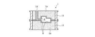
- the mold mold 1 of the present invention has at least a pair of mold parts having recesses 3a and 3b and mold matching surfaces 4a and 4b. 1a, 1b, (a) a hardened layer 8 mainly composed of a thermosetting resin is formed on the surfaces of the concave portions 3a, 3b of the green mold portions 1a, 1b and the mold-matching surfaces 4a, 4b, (b)
- the hardened layer 8 is characterized by having a hardness of 40 to 98, a thickness of 0.5 to 6 mm, and an air permeability of 70 to 150.
- the recesses 3a and 3b are a portion that forms the casting cavity 6 when the mold portions 1a and 1b are matched with each other, and a hollow portion in the mold as the runner 15 that communicates with the cavity 6. Means.
- the hardened layer 8 is mainly composed of a thermosetting resin.
- the thermosetting resin has a higher high-temperature strength than the thermoplastic resin, and can withstand the molten metal pressure in the cavity and reduce the amount of molten metal inserted into the mold.
- the thermosetting resin also has the advantage that the air permeability can be kept higher than that of water glass.
- the thermosetting resin at least one of a phenol resin, an epoxy resin, and a furan resin is preferable. Among these, a phenol resin is preferable.
- the hardened layer 8 needs to have a hardness of 40 to 98. When the hardness is 40 or more, a sufficient sand removal effect is exhibited and an iron-based casting having a good appearance can be obtained. Further, when the hardness is 98 or less, a desired air permeability is secured, there is little risk of gas defects such as pinholes, and there is no waste of thermosetting resin.
- the hardness of the hardened layer 8 is preferably 45 to 95.
- the hardness of the hardened layer 8 is measured with a self-hardness hardness meter.
- the mold parts 1a and 1b having complicated recesses there are some parts where the measured value of hardness becomes extremely small. Therefore, in order to avoid measurement errors, the hardness of the five hardened layers 8 is measured and averaged, avoiding parts with extremely small hardness measurements (ranges within 50 mm from the casting frame and deep cavities). . This measurement method is the same in the case of measuring the hardness of the semi-cured layer 7 described below.
- the hardened layer 8 needs to have a thickness of 0.5 to 6 mm. A sufficient sand removal effect can be obtained by setting the thickness of the hardened layer 8 to 0.5 mm or more. In addition, by setting the thickness of the hardened layer 8 to 6 mm or less, gas permeation when iron-based molten metal is injected into the green mold is not suppressed, and the possibility that pinholes are generated in the casting is reduced. A preferable thickness of the hardened layer 8 is 1 to 5 mm.
- the cured layer 8 needs to have an air permeability of 70 to 150. If the air permeability is less than 70, defects such as pinholes may occur. Further, in order to make the air permeability higher than 150, it is only possible to reduce the coating amount of the curing agent. However, the hardness of the cured layer 8 becomes insufficient, and the degree of sand removal at the time of mold separation is reduced. A preferable air permeability of the hardened layer 8 is 100 to 150.
- the green mold of the present invention has a relatively hard hardness of 40 to 98 because the hardened layer 8 of 0.5 to 6 mm is formed on the surfaces of the recesses 3a and 3b and the mold matching surfaces 4a and 4b. , 70-150 and sufficient air permeability. Such a feature is obtained by forming the hardened layer 8 on the mold matching surface. In addition, since the cured layer 8 is formed only on the surfaces of the recesses 3a and 3b and the mold matching surfaces 4a and 4b, an effect of reducing the amount of thermosetting resin applied can be obtained.
- the method of manufacturing the green mold of the present invention is as follows. (1) The surface of the concave portions 3a and 3b of the green mold portions 1a and 1b and the mold matching surfaces 4a and 4b are thermosetting. Applying curing agent 2 with resin as the main component and having a viscosity of 1 to 100 mPa ⁇ S, and (2) curing curing agent 2 by heating after mold matching of mold parts 1a and 1b Features.
- the curing agent is preferably an alcohol solution of a thermosetting resin so that it is dried immediately after application.
- the alcohol is not particularly limited as long as it has a low molecular weight, but ethanol, isopropyl alcohol and the like are preferable from the viewpoint of the working environment.
- the viscosity of the curing agent can be adjusted by the concentration of the thermosetting resin in the curing agent.
- the viscosity of the curing agent needs to be 1 to 100 mmPa ⁇ S. There is.
- the viscosity of the curing agent is less than 1 ⁇ mPa ⁇ S, the curing agent penetrates too deeply from the surface of the mold parts 1a and 1b, so that the curing agent hardly remains in the vicinity of the surface and has a sufficient hardness. 8 is not obtained.
- the coating amount of the curing agent is preferably 100 to 550 g / m 2 . If the coating amount of the curing agent is too small, a sufficient sand removal effect cannot be exhibited. On the other hand, if the coating amount of the curing agent is excessive, the air permeability of the green mold is reduced and gas defects are likely to occur.
- the coating amount of the curing agent is expressed by the amount (g) of the curing agent applied per plane area of the mold 1 [area (m 2 ) when the mold 1 is viewed in plan]. When a cast frame is used, the plane area is the vertical dimension of the inner surface of the cast frame ⁇ the horizontal dimension (m 2 ).
- the mold is adjusted before the curing agent is almost completely cured to form the hard cured layer 8, damage to the cured layer 8 can be prevented.
- the heating and holding time is generally about 1 to 3 minutes although it depends on the size of the green mold.
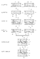
- a first method for producing a green mold of the present invention is characterized by having first and second curing steps of a curing agent. Specifically, as shown in FIG. 1, the first method is as follows: (1) Viscosity of 1 to 15 mPa ⁇ S on the surfaces of the concave portions 3a and 3b of the green mold portions 1a and 1b and the mold matching surfaces 4a and 4b. (2) Curing the curing agent 2 to a semi-cured state before mold matching to form a semi-cured layer 7, and (3) heating the semi-cured layer 7 after mold matching. Thus, the cured layer 8 is almost completely cured.
- the viscosity of the hardener 2 is as small as 1 to 15 mPa ⁇ S, the hardener 2 has a high degree of penetration into the green mold parts 1a and 1b, so the resulting hardener layer (a layer in which the sand is impregnated with the hardener) ) Has only a small hardness. Therefore, as shown in FIG. 2, after the curing agent 2 is applied to the surfaces of the recesses 3a and 3b of the green mold parts 1a and 1b and the mold matching surfaces 4a and 4b, the curing agent 2 is cured to a semi-cured state.
- the lower limit of the viscosity of the curing agent 2 is preferably 2 mPa ⁇ S or more, more preferably 3 mPa ⁇ S or more.
- the viscosity of the curing agent 2 can be adjusted by the concentration of the thermosetting resin.
- the first curing step is performed by heating the green mold parts 1a and 1b to preferably 80 to 180 ° C. for 1 to 3 minutes. More preferably, the heating temperature in the first curing step is 100 to 130 ° C., and the heating and holding time is 1 to 2 minutes.
- the hardness of the semi-cured layer 7 is preferably in the range of 30 to 45. As described above, avoiding parts with extremely small hardness measurements (in the range of 50 mm or less from the casting frame and deep cavities), measure the hardness of the five semi-cured layers 7 with a self-hardening hardness meter, and average To do. Since the semi-hardened layer 7 having a hardness of 30 or more is not crushed during mold matching, there is a low possibility that defects in dimensions and appearance will occur in the obtained iron-based casting. Further, by setting the hardness to 45 or less, the semi-cured layer 7 has sufficient deformability, and the possibility of cracking during mold matching is reduced.
- the second curing step for almost completely curing the semi-cured layer 7 is performed by heating the molded mold parts 1a and 1b, preferably at 80 to 180 ° C. for 1 to 3 minutes. More preferably, the heating temperature in the second curing step is 100 to 130 ° C., and the heating and holding time is 1 to 2 minutes.
- the obtained semi-cured layer 7 and the cured layer 8 obtained by re-curing the semi-cured layer 7 are Relatively thick.
- the thickness of the cured layer 8 (semi-cured layer 7) is preferably 2.2 to 6 mm.
- the cured layer 8 formed by the first method has a hardness of 40 to 98 and an air permeability of 70 to 150.
- the semi-cured layer 7 having a hardness that does not yield to the force acting at the time of mold matching and having a deformability that can absorb an impact at the time of mold matching is formed. Therefore, mold matching can be performed satisfactorily.
- the semi-cured layer 7 is almost completely cured by performing a second curing process after mold matching, so that a cured layer 8 having sufficient hardness can be obtained. Thus, a casting having a sound appearance can be obtained.
- the first method for producing the green mold of the present invention is as follows. (1) The surface of the recesses 3a and 3b of the green mold parts 1a and 1b and the mold matching surfaces 4a and 4b are 15 to 100. A curing agent 2 ′ having a viscosity of mPa ⁇ S is applied, and (2) the curing agent 2 ′ is cured by heating after mold matching to form a cured layer 8 that is almost completely cured.
- the curing agent 2 ' is cured in one step, so that the viscosity of the curing agent 2' is relatively large, 15 to 100 mPa ⁇ S.
- the viscosity is 15 ⁇ mPa ⁇ S or more, the curing agent 2 ′ does not easily penetrate into the mold parts 1 a and 1 b, and the obtained thin curing agent layer 7 ′ is hardly collapsed at the time of mold matching.
- the thickness of the curing agent layer 7 ' is preferably 0.5 to 2.2 mm.
- the hardness of the curing agent layer 7 'before mold matching is preferably 5-30. When the hardness is 5 or more, the curing agent layer 7 'is not crushed during mold matching. Further, if the hardness of the curing agent layer 7 ′ is 30 or less, not only there is no risk of destruction by mold matching because of sufficient deformability, but the curing layer 8 obtained from the curing agent layer 7 ′ is sufficient. Since it has gas permeability, there is little risk of gas defects such as pinholes occurring in the resulting iron casting.
- the mold parts 1a and 1b that have been matched with each other are preferably heated to 80 to 180 ° C. for 1 to 3 minutes. More preferably, the heating temperature of the curing agent layer 7 'is 100 to 130 ° C, and the heating time is 1 to 2 minutes.
- the cured layer 8 obtained by curing the curing agent layer 7 ' preferably has a thickness of 0.5 to 2.2 mm.
- the thickness of the hardened layer 8 obtained by the second method is 0.5 mm or more, a sufficient sand removal effect can be obtained.
- the thickness of the hardened layer 8 is 2.2 mm or less, gas permeation when molten metal is injected into the mold is not suppressed, and there is a low possibility that pinholes are generated in the casting.
- the cured layer 8 formed by the second method also has a hardness of 40 to 98 and an air permeability of 70 to 150.
- Example 1 Casting using green mold obtained by the first method (1) Molding step First, cast sand was prepared by kneading silica sand, water, and clay in a mass ratio of 100: 3: 1. Next, as shown in FIG. 2, the casting frame 11 (inside size: 0.5 m ⁇ 0.6 m) is set on the surface plate 13 on which the models 12a and 12b are set, and the casting sand is put inside the casting frame 11. Then, the green mold part (upper mold) 1a and the green mold part (lower mold) 1b were obtained by compressing by the Jolt skies method. NK-009 manufactured by Nakayama Co., Ltd.
- the hardness of five locations was measured by the self-hardness hardness tester on the flat surfaces of the mating surfaces 4a and 4b of the upper mold 1a and lower mold 1b separated from the casting frame 11 by 50 mm or more.
- the hardness was determined by measuring and averaging. As a result, the hardness was 20 for both the upper mold 1a and the lower mold 1b.
- Second curing step The semi-cured layer 7 was cured again by pumping hot air of 105 ° C. from the gate 15 to the cavity 6 to form a cured layer 8 having a thickness of 3 mm.
- the hardness of the cured layer 8 measured by the same method as described above was 76. Further, the air permeability of the hardened layer 8 was 110.
- the degree of sand removal is the relative value of the mass of cast sand adhering to the runner and the product after mold breaking, when the mass in Comparative Example 1 is 100%. It shows that casting sand adhering to the obtained casting can be easily removed as the degree of sand removal is small.
- Comparative Example 1 As shown in FIG. 4, a green mold 1 was produced in the same manner as in Example 1 except that no curing agent was applied, and the degree of sand removal during mold breaking and the appearance of the casting were evaluated. The results are shown in Table 1. The air permeability of the concave portion 35 of the mold 1 without applying the curing agent was 160. Moreover, since no curing agent was applied, sand removal during mold breaking was poor.
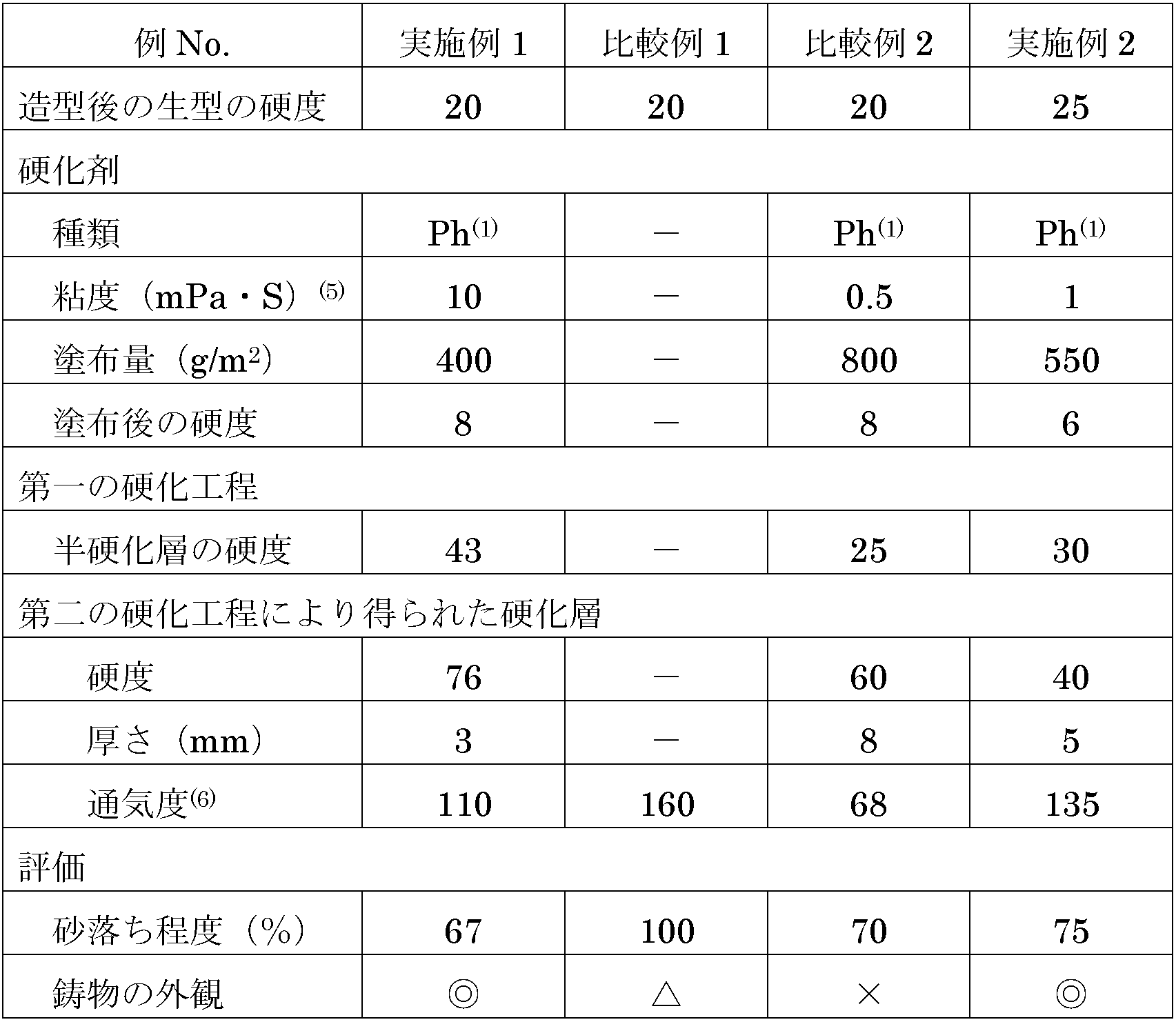
- Comparative Example 2 The mold 1 was produced in the same manner as in Example 1 except that the viscosity of the first curing agent was 0.5 mPa ⁇ S, the coating amount of the curing agent was 800 g / m 2, and the thickness of the cured layer was 8 mm. Then, the degree of sand removal during mold breaking and the appearance of the casting were evaluated. The results are shown in Table 1. The hardness of the semi-cured layer 7 was 25. Further, the hardness of the hardened layer 8 was 60, and the air permeability was 68.
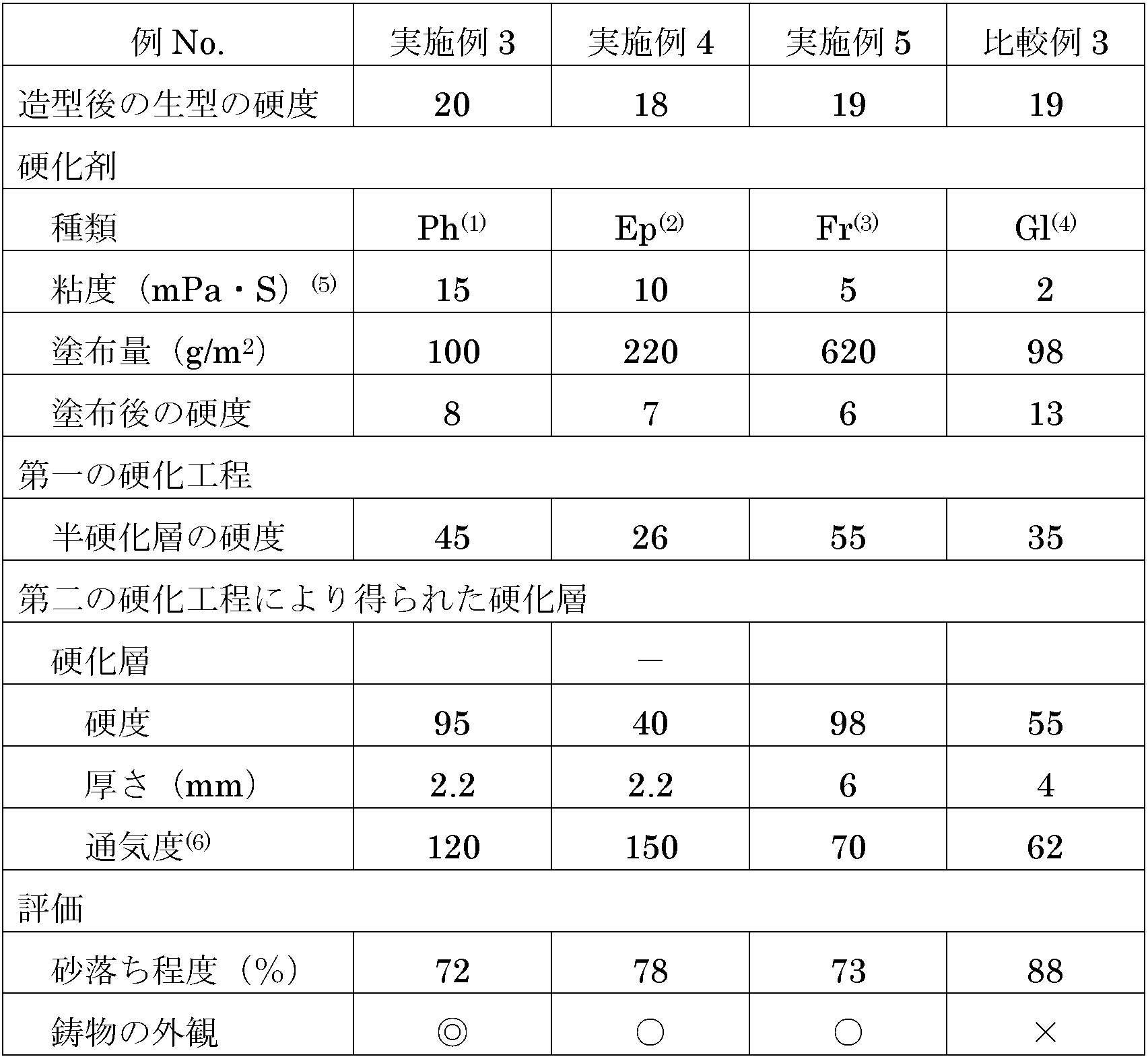
- Example 2 to 5 and Comparative Example 3 The raw mold 1 was produced in the same manner as in Example 1 except that the type, viscosity and coating amount of the curing agent, the first curing step and the second curing step were changed as shown in Table 1, The degree of sand removal and the appearance of the casting were evaluated. The hardness after the first curing step and after the second curing step was changed by changing the curing time. The results are shown in Table 1.
- a 1 to 15 mPa ⁇ S curing agent is applied to the mold-mating surface of the green mold after molding, and a semi-cured layer is formed in the first curing process.
- the degree of sand removal during mold breaking was good, and the appearance of the casting was also good.
- a phenol resin is used as the thermosetting resin
- the semi-cured layer has a hardness in the range of 30 to 45
- the cured layer has a hardness in the range of 40 to 98, 2.2 to 6 Since it had a thickness in the range of mm and an air permeability in the range of 70 to 150, the degree of sand removal and the appearance of the casting were very good.
- the casting obtained in Example 4 slight burrs due to deformation of the parting part were confirmed, but the appearance was generally good ( ⁇ ).
- pinholes and seizures were observed in the casting obtained in Example 5, but the overall appearance was good ( ⁇ ).
- Comparative Example 1 since the curing agent was not applied, the air permeability of the recess was 160, but the sand drop at the time of mold separation was poor.
- Comparative Example 2 the viscosity of the curing agent was less than 1 mPa ⁇ S. As a result of applying a large amount of curing agent, the air permeability was less than 70, pinholes were generated, and the appearance of the casting was poor ( ⁇ ) In addition, the parting part of the casting was deformed. Further, since water glass was used as the curing agent in Comparative Example 3, the air permeability of the cured layer 8 was 62, and both the degree of sand removal and the appearance of the casting were bad.
- Example 6 Casting using a green mold obtained by the second method
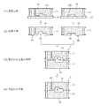
- An ethanol solution of a phenol resin having a viscosity adjusted to 25 mPa ⁇ S was used as the curing agent 2, and the second method of the present invention as shown in FIG.
- the mold 1 was manufactured in the same manner as in Example 1 except that the curing agent 2 was almost completely cured after mold matching, and the degree of sand removal during mold breaking and the appearance of the casting were evaluated.
- the time from completion of the application of the curing agent to mold matching was 2 minutes.
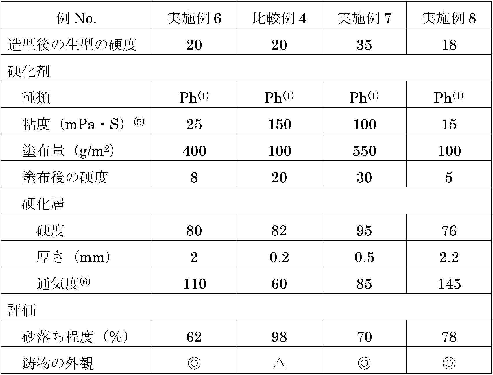
- the results are shown in Table 2. As is apparent from Table 2, the hardness after application of the curing agent was 8, the hardness of the cured layer 8 was 80, and the thickness was 2 mm.
- Comparative Example 4 A green mold 1 was produced in the same manner as in Example 6 except that the viscosity of the curing agent 2 was 150 mPa ⁇ S, and the degree of sand removal during mold breaking and the appearance of the casting were evaluated. The results are shown in Table 2. As is apparent from Table 2, the curing agent 2 hardly penetrates into the green mold 1 because of its high viscosity, and the thickness of the cured layer 8 was 0.2 mm. Since this hardened layer 8 did not have an anchoring effect on the surface of the green mold 1, it partially peeled off, and the molten metal was inserted into the exposed sand mold portion, resulting in poor seizure.
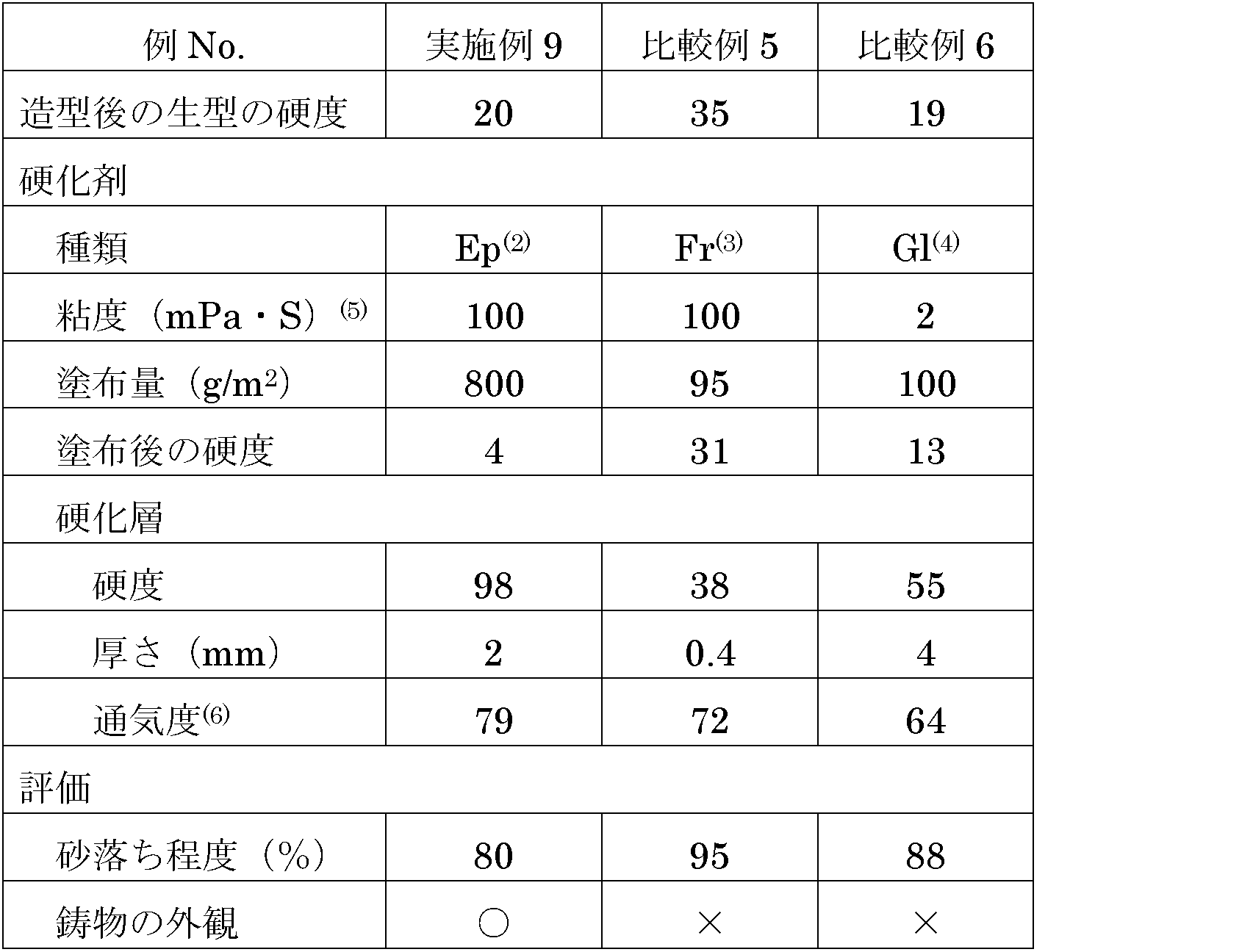
- Example 7-9 and Comparative Examples 5 and 6 The raw mold 1 was produced in the same manner as in Example 6 except that the type of curing agent, the coating amount of the curing agent, the viscosity of the curing agent, and the measured value of hardness before mold matching were changed as shown in Table 2. The degree of sand removal during ballasting and the appearance of the casting were evaluated. The results are shown in Table 2.
- Comparative Example 4 since the viscosity of the curing agent was more than 100 ⁇ mPa ⁇ S, the cured layer dropped off and a seizure defect occurred.
- Comparative Example 5 since the thickness of the hardened layer was less than 0.5 mm, both the degree of sand removal and the appearance of the casting were bad.
- Comparative Example 6 since the air permeability was less than 70, gas defects such as pinholes occurred in the iron-based casting, and the appearance was poor.
Landscapes
- Engineering & Computer Science (AREA)
- Mechanical Engineering (AREA)
- Chemical & Material Sciences (AREA)
- Materials Engineering (AREA)
- Mold Materials And Core Materials (AREA)
Abstract
Description
各生型部の凹部面及び型合わせ面に、熱硬化性樹脂を主成分とし、かつ1~100 mPa・Sの粘度を有する硬化剤を塗布し、
前記生型部の型合わせ後に加熱することにより、前記硬化剤を硬化させることを特徴とする。
各生型部の凹部面及び型合わせ面に1~15 mPa・Sの粘度を有する硬化剤を塗布し、
型合わせ前に前記硬化剤を半硬化状態まで硬化させて、半硬化層を形成し、
型合わせ後に前記半硬化層を加熱することにより、ほぼ完全に硬化した硬化層とすることを特徴とする。
各生型部の凹部面及び型合わせ面に15~100 mPa・Sの粘度を有する硬化剤を塗布し、
型合わせ後に加熱することにより前記硬化剤を硬化させ、ほぼ完全に硬化した硬化層とすることを特徴とする。
前記生型部を型合わせした後、加熱することにより前記硬化層を形成し、
型合わせした前記生型部の凹部により形成されたキャビティに鉄系溶湯を充填することを特徴とする。
図1(a) 及び図1(b) に示すように、本発明の生型鋳型1は、凹部3a,3b及び型合わせ面4a,4bを有する少なくとも一対の生型部1a,1bを有し、(a) 各生型部1a,1bの凹部3a,3bの表面及び型合わせ面4a,4bに熱硬化性樹脂を主成分とする硬化層8が形成されており、(b) 硬化層8が40~98の硬度、0.5~6 mmの厚さ、及び70~150の通気度を有することを特徴とする。ここで、凹部3a,3bは、生型部1a,1bを型合わせしたときに鋳造用キャビティ6を形成する部分、及びキャビティ6に連通する湯道15のように生型鋳型内にある空洞部を意味する。
本発明の生型鋳型を製造する方法は、(1) 各生型部1a,1bの凹部3a,3bの表面及び型合わせ面4a,4bに、熱硬化性樹脂を主成分とし、かつ1~100 mPa・Sの粘度を有する硬化剤2を塗布し、(2) 生型部1a,1bの型合わせ後に加熱することにより、硬化剤2を硬化させることを特徴とする。
本発明の生型鋳型を製造する第一の方法は硬化剤の第一及び第二の硬化工程を有することを特徴とする。具体的には図1に示すように、第一の方法は、(1) 各生型部1a,1bの凹部3a,3bの表面及び型合わせ面4a,4bに1~15 mPa・Sの粘度を有する硬化剤2を塗布し、(2) 型合わせ前に硬化剤2を半硬化状態まで硬化させて、半硬化層7を形成し、(3) 型合わせ後に半硬化層7を加熱することにより、ほぼ完全に硬化した硬化層8とすることを特徴とする。
本発明の生型鋳型を製造する第一の方法は、(1) 各生型部1a,1bの凹部3a,3bの表面及び型合わせ面4a,4bに15~100 mPa・Sの粘度を有する硬化剤2’を塗布し、(2) 型合わせ後に加熱することにより硬化剤2’を硬化させ、ほぼ完全に硬化した硬化層8とすることを特徴とする。
第一の方法により得られた生型鋳型を用いた鋳造
(1) 造型工程
まず珪砂と水と粘土とを質量比で100:3:1の割合で混練することにより鋳砂を調製した。次に、図2に示すように、模型12a,12bをセットした定盤13上に鋳枠11(内側のサイズ:0.5 m×0.6 m)をセットし、鋳枠11の内側に鋳砂を投入した後、ジョルトスキーズ法で圧縮することにより生型部(上型)1a及び生型部(下型)1bを得た。株式会社ナカヤマ製のNK-009を使用し、鋳枠11から50 mm以上離れた上型1a,下型1bの型合わせ面4a,4bの平面部において、自硬性硬度計により5ヶ所の硬度を測定し、平均することにより硬度を求めた。その結果、硬度は上型1a及び下型1bのいずれも20であった。
上型1a,下型1bの凹部3a,3bの表面及び型合わせ面4a,4bに、塗布装置14を用いた噴霧法によりフェノール樹脂のエタノール溶液(粘度:10 mPa・S)からなる硬化剤2を塗布し、乾燥した。上型1a及び下型1bの各型合わせ面4a,4bに塗布した硬化剤2の量は120 gであり、型合わせ面4a,4bの面積当たり400 g/m2であった。上記と同様に測定した硬化剤2塗布後の硬度は8であった。
型合わせ面4a,4bに塗布した硬化剤層を白熱灯で105℃に1分間加熱し、半硬化させた。得られる半硬化層7の硬度は白熱灯の温度及び点灯時間により調節可能である。上記と同様に測定した半硬化層7の硬度は43であった。
型合わせ面4a,4bに半硬化層7を形成した上型1a及び下型1bを型合わせした。
湯口15より105℃の温風をキャビティ6に圧送することにより半硬化層7を再度硬化させ、厚さ3 mmの硬化層8を形成した。上記と同じ方法で測定した硬化層8の硬度は76であった。また、硬化層8の通気度は110であった。
完成した生型1に溶湯を注湯した後、型バラシ時の砂落ち程度、及び得られた鋳物の外観を観察した。結果を表1に示す。砂落ち程度は、型バラシ後の湯道及び製品に付着した鋳砂の質量を、比較例1における質量を100%としたときの相対値で表したものである。砂落ち程度が小さいほど、得られた鋳物に付着した鋳砂を容易に除去できることを示す。
図4に示すように硬化剤を塗布しない以外実施例1と同様にして、生型1を製造し、型バラシ時の砂落ち程度及び鋳物の外観を評価した。結果を表1に示す。硬化剤を塗布しない生型1の凹部35の通気度は160であった。また硬化剤を塗布していないため、型バラシ時の砂落ちが悪かった。
第一の硬化剤の粘度を0.5 mPa・Sとし、硬化剤の塗布量を800 g/m2とし、硬化層の厚さを8 mmとした以外実施例1と同様にして生型1を製造し、型バラシ時の砂落ち程度及び鋳物の外観を評価した。結果を表1に示す。半硬化層7の硬度は25であった。また、硬化層8の硬度は60であり、通気度は68であった。
硬化剤の種類、粘度及び塗布量、第一の硬化工程及び第二の硬化工程を表1に示すように変化させた以外実施例1と同様にして生型1を製造し、型バラシ時の砂落ち程度及び鋳物の外観を評価した。第一硬化工程後及び第二の硬化工程後の硬度は硬化時間を変えるこれにより変化させた。結果を表1に示す。
(5) JIS K6910に従ってブルックフィールド粘度計により測定した粘度。
(6) JIS Z 2601の付属書3に記載された迅速法により測定。
(2) エポキシ樹脂。
(3) フラン樹脂。
(4) 水ガラス。
(5) JIS K6910に従ってブルックフィールド粘度計により測定した粘度。
(6) JIS Z 2601の付属書3に記載された迅速法により測定。
第二の方法により得られた生型鋳型を用いた鋳造
粘度を25 mPa・Sに調整したフェノール樹脂のエタノール溶液を硬化剤2として用い、かつ図3に示すように本発明の第二の方法により硬化剤2を型合わせ後にほぼ完全に硬化させた以外、実施例1と同様にして生型1を製造し、型バラシ時の砂落ち程度及び鋳物の外観を評価した。なお、硬化剤の塗布の終了後型合わせまでの時間は2分であった。結果を表2に示す。表2から明らかなように、硬化剤の塗布後の硬度は8であり、硬化層8の硬度は80でありかつ厚さは2 mmであった。
硬化剤2の粘度を150 mPa・Sとした以外実施例6と同様にして生型1を製造し、型バラシ時の砂落ち程度及び鋳物の外観を評価した。結果を表2に示す。表2から明らかなように、硬化剤2は粘度が大きいために生型1にほとんど浸透せず、硬化層8の厚さは0.2 mmであった。この硬化層8は生型1表面へのアンカー効果を有さないので、部分的に剥離し、露出した砂型部分に溶湯が差し込み、焼き付き不良が発生した。
硬化剤の種類、硬化剤の塗布量、硬化剤の粘度、型合わせ前の硬度の測定値を表2に示すように変えた以外、実施例6と同様にして生型1を製造し、型バラシ時の砂落ち程度及び鋳物の外観を評価した。結果を表2に示す。
(5) JIS K6910に従ってブルックフィールド粘度計により測定した粘度。
(6) JIS Z 2601の付属書3に記載された迅速法により測定。
(3) フラン樹脂。
(4) 水ガラス。
(5) JIS K6910に従ってブルックフィールド粘度計により測定した粘度。
(6) JIS Z 2601の付属書3に記載された迅速法により測定。
1a,1b:生型部
2:硬化剤
3a,3b:凹部
4a,4b:型合わせ面
6:キャビティ
7:半硬化層
7’:硬化剤層
8:硬化層
11:鋳枠
12a,12b:模型
13:定盤
14:塗布装置
15:湯道
Claims (12)
- 凹部及び型合わせ面を有する少なくとも一対の生型部を有する生型鋳型であって、各生型部の凹部面及び型合わせ面に熱硬化性樹脂を主成分とする硬化層が形成されており、前記硬化層が40~98の硬度、0.5~6 mmの厚さ、及び70~150の通気度を有することを特徴とする生型鋳型。
- 請求項1に記載の生型鋳型において、前記熱硬化性樹脂がフェノール樹脂、エポキシ樹脂及びフラン樹脂の少なくとも一種であることを特徴とする生型鋳型。
- 請求項1又は2に記載の生型鋳型を製造する方法において、
各生型部の凹部面及び型合わせ面に、熱硬化性樹脂を主成分とし、かつ1~100 mPa・Sの粘度を有する硬化剤を塗布し、
前記生型部の型合わせ後に加熱することにより、前記硬化剤を硬化させることを特徴とする生型鋳型の製造方法。 - 請求項3に記載の生型鋳型の製造方法において、前記硬化剤が熱硬化性樹脂のアルコール溶液であることを特徴とする生型鋳型の製造方法。
- 請求項3又は4に記載の生型鋳型の製造方法において、前記硬化剤の塗布量が100~550 g/m2であることを特徴とする生型鋳型の製造方法。
- 請求項3~5のいずれかに記載の生型鋳型の製造方法において、
各生型部の凹部面及び型合わせ面に1~15 mPa・Sの粘度を有する硬化剤を塗布し、
型合わせ前に前記硬化剤を半硬化状態まで硬化させて、半硬化層を形成し、
型合わせ後に前記半硬化層を加熱することにより、ほぼ完全に硬化した硬化層とすることを特徴とする生型鋳型の製造方法。 - 請求項6に記載の生型鋳型の製造方法において、前記半硬化層の硬度が30~45であることを特徴とする生型鋳型の製造方法。
- 請求項6又は7に記載の生型鋳型の製造方法において、前記硬化層の厚さが2.2~6 mmであることを特徴とする生型鋳型の製造方法。
- 請求項3~5のいずれかに記載の生型鋳型の製造方法において、
各生型部の凹部面及び型合わせ面に15~100 mPa・Sの粘度を有する硬化剤を塗布し、
型合わせ後に加熱することにより前記硬化剤を硬化させ、ほぼ完全に硬化した硬化層とすることを特徴とする生型鋳型の製造方法。 - 請求項9に記載の生型鋳型の製造方法において、型合わせ前の硬化剤層の硬度が5~30であることを特徴とする生型鋳型の製造方法。
- 請求項9又は10に記載の生型鋳型の製造方法において、前記硬化層の厚さが0.5~2.2 mmであることを特徴とする生型鋳型の製造方法。
- 請求項1又は2に記載の生型鋳型を用いて鉄系鋳物を製造する方法であって、
前記生型部を型合わせした後、加熱することにより前記硬化層を形成し、
型合わせした前記生型部の凹部により形成されたキャビティに鉄系溶湯を充填することを特徴とする鉄系鋳物の製造方法。
Priority Applications (5)
| Application Number | Priority Date | Filing Date | Title |
|---|---|---|---|
| JP2015539452A JP6387966B2 (ja) | 2013-09-30 | 2014-09-30 | 生型鋳型及びその製造方法、並びに鉄系鋳物の製造方法 |
| CN201480054041.7A CN105592955B (zh) | 2013-09-30 | 2014-09-30 | 湿型铸型及其制造方法以及铁系铸件的制造方法 |
| US15/023,845 US10946435B2 (en) | 2013-09-30 | 2014-09-30 | Green sand mold and its production method, and production method of iron-based casting |
| KR1020167011473A KR102179841B1 (ko) | 2013-09-30 | 2014-09-30 | 생형 주형 및 그 제조 방법, 및 철계 주물의 제조 방법 |
| EP14849585.6A EP3053671B1 (en) | 2013-09-30 | 2014-09-30 | Green sand casting mold, manufacturing method therefor, and method for manufacturing cast iron object |
Applications Claiming Priority (2)
| Application Number | Priority Date | Filing Date | Title |
|---|---|---|---|
| JP2013-203816 | 2013-09-30 | ||
| JP2013203816 | 2013-09-30 |
Publications (1)
| Publication Number | Publication Date |
|---|---|
| WO2015046562A1 true WO2015046562A1 (ja) | 2015-04-02 |
Family
ID=52743683
Family Applications (1)
| Application Number | Title | Priority Date | Filing Date |
|---|---|---|---|
| PCT/JP2014/076041 Ceased WO2015046562A1 (ja) | 2013-09-30 | 2014-09-30 | 生型鋳型及びその製造方法、並びに鉄系鋳物の製造方法 |
Country Status (6)
| Country | Link |
|---|---|
| US (1) | US10946435B2 (ja) |
| EP (1) | EP3053671B1 (ja) |
| JP (1) | JP6387966B2 (ja) |
| KR (1) | KR102179841B1 (ja) |
| CN (1) | CN105592955B (ja) |
| WO (1) | WO2015046562A1 (ja) |
Families Citing this family (5)
| Publication number | Priority date | Publication date | Assignee | Title |
|---|---|---|---|---|
| EP3124134A4 (en) * | 2014-03-26 | 2017-11-22 | Hitachi Metals, Ltd. | Green sand for casting of steel castings, method for producing same, and method for producing metal castings using said green sand |
| US11021187B2 (en) | 2017-12-08 | 2021-06-01 | ILJIN USA Corporation | Steering knuckle and method of making the same |
| PL243474B1 (pl) * | 2018-05-28 | 2023-08-28 | Abb Spolka Z Ograniczona Odpowiedzialnoscia | Sposób wykonywania form piaskowych zabezpieczonych powłoką ochronną |
| CN112008041A (zh) * | 2019-05-31 | 2020-12-01 | 共享智能铸造产业创新中心有限公司 | 模型及提高模型表面硬度的方法 |
| CN119199017B (zh) * | 2024-08-30 | 2025-10-31 | 华中科技大学 | 一种评估造型工艺导致铸件夹砂、粘砂缺陷风险的模具及方法 |
Citations (4)
| Publication number | Priority date | Publication date | Assignee | Title |
|---|---|---|---|---|
| JPS5910446A (ja) | 1982-07-09 | 1984-01-19 | Akebono Brake Ind Co Ltd | 砂型の砂落防止法 |
| JPS6171153A (ja) | 1984-09-14 | 1986-04-12 | Sintokogio Ltd | 鋳型の造型方法 |
| JPS63295040A (ja) * | 1987-05-28 | 1988-12-01 | Honda Motor Co Ltd | 消失模型 |
| JP2013140102A (ja) * | 2012-01-05 | 2013-07-18 | Denshi Rika Kogyo Kk | 溶融金属の試料採取装置 |
Family Cites Families (18)
| Publication number | Priority date | Publication date | Assignee | Title |
|---|---|---|---|---|
| US2273326A (en) * | 1940-07-08 | 1942-02-17 | Cortner M Hardy | Sand mold |
| US2313674A (en) * | 1942-09-11 | 1943-03-09 | Borden Co | Coating foundry mold surfaces |
| US2425978A (en) * | 1943-11-13 | 1947-08-19 | Hercules Powder Co Ltd | Foundry mold coating |
| GB747579A (en) * | 1953-09-23 | 1956-04-11 | English Steel Corp Ltd | Improvements in mould paints |
| GB1127030A (en) * | 1965-12-30 | 1968-09-11 | Foseco Int | Treatment of ingot moulds |
| US3654261A (en) * | 1968-06-27 | 1972-04-04 | Cpc International Inc | Quaternary ammonium alkoxide alkoxy polyol compounds |
| JPS5110815B2 (ja) * | 1972-05-22 | 1976-04-07 | ||
| CA1144338A (en) * | 1978-05-25 | 1983-04-12 | Enno H. Page | Expendable cores for die casting |
| JPS6156752A (ja) * | 1984-08-24 | 1986-03-22 | Sintokogio Ltd | 鋳型及びその造型方法 |
| US4636262A (en) * | 1986-03-11 | 1987-01-13 | Reed Edgar H | Additive for green molding sand |
| JPS62248535A (ja) * | 1986-04-18 | 1987-10-29 | Sintokogio Ltd | 砂型の型合せ面処理方法 |
| US4763720A (en) * | 1986-06-23 | 1988-08-16 | Kabushiki Kaisha Komatsu Seisakusho | Microwave process for the fabrication of cores for use in foundry casting |
| JPS6411047A (en) * | 1987-07-03 | 1989-01-13 | Hodogaya Ashiyurando Kk | Method for curing mold surface |
| JP4205940B2 (ja) * | 2002-12-19 | 2009-01-07 | アイシン高丘株式会社 | 振動減衰能及び強度に優れたねずみ鋳鉄の製造方法 |
| US8137607B2 (en) * | 2006-11-07 | 2012-03-20 | Ford Motor Company | Process for making reusable tooling |
| JP2009125799A (ja) | 2007-11-28 | 2009-06-11 | Aisin Takaoka Ltd | 生砂鋳型製造方法 |
| CN102205398B (zh) * | 2011-04-21 | 2013-06-05 | 安徽应流铸业有限公司 | 呋喃树脂砂无箱造型壳型的制备方法 |
| CN102756094A (zh) * | 2011-04-27 | 2012-10-31 | 陆宝庆 | 缸套的铸造工艺 |
-
2014
- 2014-09-30 KR KR1020167011473A patent/KR102179841B1/ko not_active Expired - Fee Related
- 2014-09-30 JP JP2015539452A patent/JP6387966B2/ja not_active Expired - Fee Related
- 2014-09-30 EP EP14849585.6A patent/EP3053671B1/en active Active
- 2014-09-30 US US15/023,845 patent/US10946435B2/en not_active Expired - Fee Related
- 2014-09-30 CN CN201480054041.7A patent/CN105592955B/zh not_active Expired - Fee Related
- 2014-09-30 WO PCT/JP2014/076041 patent/WO2015046562A1/ja not_active Ceased
Patent Citations (4)
| Publication number | Priority date | Publication date | Assignee | Title |
|---|---|---|---|---|
| JPS5910446A (ja) | 1982-07-09 | 1984-01-19 | Akebono Brake Ind Co Ltd | 砂型の砂落防止法 |
| JPS6171153A (ja) | 1984-09-14 | 1986-04-12 | Sintokogio Ltd | 鋳型の造型方法 |
| JPS63295040A (ja) * | 1987-05-28 | 1988-12-01 | Honda Motor Co Ltd | 消失模型 |
| JP2013140102A (ja) * | 2012-01-05 | 2013-07-18 | Denshi Rika Kogyo Kk | 溶融金属の試料採取装置 |
Also Published As
| Publication number | Publication date |
|---|---|
| US20160236268A1 (en) | 2016-08-18 |
| EP3053671B1 (en) | 2021-05-26 |
| EP3053671A4 (en) | 2017-04-26 |
| CN105592955A (zh) | 2016-05-18 |
| JP6387966B2 (ja) | 2018-09-12 |
| CN105592955B (zh) | 2018-01-26 |
| KR102179841B1 (ko) | 2020-11-17 |
| EP3053671A1 (en) | 2016-08-10 |
| KR20160064215A (ko) | 2016-06-07 |
| US10946435B2 (en) | 2021-03-16 |
| JPWO2015046562A1 (ja) | 2017-03-09 |
Similar Documents
| Publication | Publication Date | Title |
|---|---|---|
| JP6387966B2 (ja) | 生型鋳型及びその製造方法、並びに鉄系鋳物の製造方法 | |
| CN105382206B (zh) | 一种齿轮箱箱体铸型及其成型方法 | |
| CN102921902B (zh) | 铁模覆砂与铁型组芯复合造型工艺方法 | |
| CN104400879A (zh) | 一种3d成型陶瓷模具制作的方法 | |
| CN106866124A (zh) | 一种水溶性陶瓷型芯及其制备方法 | |
| CN105665635B (zh) | 一种超大厚壁球铁件的铸造方法 | |
| CN102717026A (zh) | 一种填充金属粉浆料的光固化模具及其制作方法 | |
| CN108127082A (zh) | 一种型壳防变形工艺 | |
| JP6662293B2 (ja) | 鋳造用生型、及びそれを用いた鋳造物品の製造方法 | |
| CN101195148A (zh) | 以再生砂为原砂的覆膜砂制造的凸轮轴砂型及其制造方法 | |
| JP5136094B2 (ja) | タイヤ加硫用モールドの製造方法 | |
| CN205236971U (zh) | 一种齿轮箱箱体铸型 | |
| CN108273963A (zh) | 一种防止铸件厚大壁处产生缩松缺陷的铸造方法 | |
| RU2018143346A (ru) | Способ изготовления корпуса клапана, имеющего одну или более коррозионно-стойких внутренних поверхностей | |
| EP1768168A3 (en) | Method of resin seal moulding electronic component and apparatus therefor | |
| KR100288497B1 (ko) | 신발금형 제조방법 | |
| KR20160039402A (ko) | 생형 몰드와 셸 몰드를 결합시킨 복합주조공정을 이용한 주조품의 제조방법 | |
| CN117324540A (zh) | 一种基于水溶陶瓷型芯的熔模精铸厚大铸件蜡型的制备方法 | |
| CN103128269B (zh) | 一种用于制造铁路货车制动产品的方法 | |
| CN112496264B (zh) | 一种无激沟缺陷的树脂砂铸件制备方法 | |
| CN110560664B (zh) | 铸件及其浇注方法和应用、汽车车轮的铸造方法和汽车车轮 | |
| CN104441354A (zh) | 一种电子蜡烛模具的加工工艺 | |
| CN102205398A (zh) | 呋喃树脂砂无箱造型壳型的制备方法 | |
| TW202039201A (zh) | 中介模具製作方法 | |
| CN205167595U (zh) | 提高制件表面质量的热压罐模具 |
Legal Events
| Date | Code | Title | Description |
|---|---|---|---|
| 121 | Ep: the epo has been informed by wipo that ep was designated in this application |
Ref document number: 14849585 Country of ref document: EP Kind code of ref document: A1 |
|
| ENP | Entry into the national phase |
Ref document number: 2015539452 Country of ref document: JP Kind code of ref document: A |
|
| WWE | Wipo information: entry into national phase |
Ref document number: 15023845 Country of ref document: US |
|
| NENP | Non-entry into the national phase |
Ref country code: DE |
|
| REEP | Request for entry into the european phase |
Ref document number: 2014849585 Country of ref document: EP |
|
| WWE | Wipo information: entry into national phase |
Ref document number: 2014849585 Country of ref document: EP |
|
| ENP | Entry into the national phase |
Ref document number: 20167011473 Country of ref document: KR Kind code of ref document: A |