WO2015049840A1 - コンテナ用冷凍装置 - Google Patents
コンテナ用冷凍装置 Download PDFInfo
- Publication number
- WO2015049840A1 WO2015049840A1 PCT/JP2014/004761 JP2014004761W WO2015049840A1 WO 2015049840 A1 WO2015049840 A1 WO 2015049840A1 JP 2014004761 W JP2014004761 W JP 2014004761W WO 2015049840 A1 WO2015049840 A1 WO 2015049840A1
- Authority
- WO
- WIPO (PCT)
- Prior art keywords
- air
- container
- unit
- adsorption
- mixed gas
- Prior art date
- Legal status (The legal status is an assumption and is not a legal conclusion. Google has not performed a legal analysis and makes no representation as to the accuracy of the status listed.)
- Ceased
Links
Images











Classifications
-
- A—HUMAN NECESSITIES
- A23—FOODS OR FOODSTUFFS; TREATMENT THEREOF, NOT COVERED BY OTHER CLASSES
- A23B—PRESERVATION OF FOODS, FOODSTUFFS OR NON-ALCOHOLIC BEVERAGES; CHEMICAL RIPENING OF FRUIT OR VEGETABLES
- A23B7/00—Preservation of fruit or vegetables; Chemical ripening of fruit or vegetables
- A23B7/04—Freezing; Subsequent thawing; Cooling
- A23B7/0425—Materials not being transported through or in the apparatus, with or without shaping, e.g. in the form of powders, granules or flakes
-
- F—MECHANICAL ENGINEERING; LIGHTING; HEATING; WEAPONS; BLASTING
- F25—REFRIGERATION OR COOLING; COMBINED HEATING AND REFRIGERATION SYSTEMS; HEAT PUMP SYSTEMS; MANUFACTURE OR STORAGE OF ICE; LIQUEFACTION SOLIDIFICATION OF GASES
- F25B—REFRIGERATION MACHINES, PLANTS OR SYSTEMS; COMBINED HEATING AND REFRIGERATION SYSTEMS; HEAT PUMP SYSTEMS
- F25B17/00—Sorption machines, plants or systems, operating intermittently, e.g. absorption or adsorption type
- F25B17/02—Sorption machines, plants or systems, operating intermittently, e.g. absorption or adsorption type the absorbent or adsorbent being a liquid, e.g. brine
-
- B—PERFORMING OPERATIONS; TRANSPORTING
- B01—PHYSICAL OR CHEMICAL PROCESSES OR APPARATUS IN GENERAL
- B01D—SEPARATION
- B01D53/00—Separation of gases or vapours; Recovering vapours of volatile solvents from gases; Chemical or biological purification of waste gases, e.g. engine exhaust gases, smoke, fumes, flue gases, aerosols
- B01D53/02—Separation of gases or vapours; Recovering vapours of volatile solvents from gases; Chemical or biological purification of waste gases, e.g. engine exhaust gases, smoke, fumes, flue gases, aerosols by adsorption, e.g. preparative gas chromatography
- B01D53/04—Separation of gases or vapours; Recovering vapours of volatile solvents from gases; Chemical or biological purification of waste gases, e.g. engine exhaust gases, smoke, fumes, flue gases, aerosols by adsorption, e.g. preparative gas chromatography with stationary adsorbents
- B01D53/047—Pressure swing adsorption
-
- B—PERFORMING OPERATIONS; TRANSPORTING
- B65—CONVEYING; PACKING; STORING; HANDLING THIN OR FILAMENTARY MATERIAL
- B65D—CONTAINERS FOR STORAGE OR TRANSPORT OF ARTICLES OR MATERIALS, e.g. BAGS, BARRELS, BOTTLES, BOXES, CANS, CARTONS, CRATES, DRUMS, JARS, TANKS, HOPPERS, FORWARDING CONTAINERS; ACCESSORIES, CLOSURES, OR FITTINGS THEREFOR; PACKAGING ELEMENTS; PACKAGES
- B65D81/00—Containers, packaging elements, or packages, for contents presenting particular transport or storage problems, or adapted to be used for non-packaging purposes after removal of contents
- B65D81/24—Adaptations for preventing deterioration or decay of contents; Applications to the container or packaging material of food preservatives, fungicides, pesticides or animal repellants
- B65D81/26—Adaptations for preventing deterioration or decay of contents; Applications to the container or packaging material of food preservatives, fungicides, pesticides or animal repellants with provision for draining away, or absorbing, or removing by ventilation, fluids, e.g. exuded by contents; Applications of corrosion inhibitors or desiccators
- B65D81/266—Adaptations for preventing deterioration or decay of contents; Applications to the container or packaging material of food preservatives, fungicides, pesticides or animal repellants with provision for draining away, or absorbing, or removing by ventilation, fluids, e.g. exuded by contents; Applications of corrosion inhibitors or desiccators for absorbing gases, e.g. oxygen absorbers or desiccants
-
- C—CHEMISTRY; METALLURGY
- C01—INORGANIC CHEMISTRY
- C01B—NON-METALLIC ELEMENTS; COMPOUNDS THEREOF; METALLOIDS OR COMPOUNDS THEREOF NOT COVERED BY SUBCLASS C01C
- C01B21/00—Nitrogen; Compounds thereof
- C01B21/04—Purification or separation of nitrogen
- C01B21/0405—Purification or separation processes
- C01B21/0433—Physical processing only
- C01B21/045—Physical processing only by adsorption in solids
-
- F—MECHANICAL ENGINEERING; LIGHTING; HEATING; WEAPONS; BLASTING
- F25—REFRIGERATION OR COOLING; COMBINED HEATING AND REFRIGERATION SYSTEMS; HEAT PUMP SYSTEMS; MANUFACTURE OR STORAGE OF ICE; LIQUEFACTION SOLIDIFICATION OF GASES
- F25B—REFRIGERATION MACHINES, PLANTS OR SYSTEMS; COMBINED HEATING AND REFRIGERATION SYSTEMS; HEAT PUMP SYSTEMS
- F25B49/00—Arrangement or mounting of control or safety devices
- F25B49/04—Arrangement or mounting of control or safety devices for sorption type machines, plants or systems
-
- F—MECHANICAL ENGINEERING; LIGHTING; HEATING; WEAPONS; BLASTING
- F25—REFRIGERATION OR COOLING; COMBINED HEATING AND REFRIGERATION SYSTEMS; HEAT PUMP SYSTEMS; MANUFACTURE OR STORAGE OF ICE; LIQUEFACTION SOLIDIFICATION OF GASES
- F25D—REFRIGERATORS; COLD ROOMS; ICE-BOXES; COOLING OR FREEZING APPARATUS NOT OTHERWISE PROVIDED FOR
- F25D11/00—Self-contained movable devices, e.g. domestic refrigerators
- F25D11/003—Transport containers
-
- F—MECHANICAL ENGINEERING; LIGHTING; HEATING; WEAPONS; BLASTING
- F25—REFRIGERATION OR COOLING; COMBINED HEATING AND REFRIGERATION SYSTEMS; HEAT PUMP SYSTEMS; MANUFACTURE OR STORAGE OF ICE; LIQUEFACTION SOLIDIFICATION OF GASES
- F25D—REFRIGERATORS; COLD ROOMS; ICE-BOXES; COOLING OR FREEZING APPARATUS NOT OTHERWISE PROVIDED FOR
- F25D17/00—Arrangements for circulating cooling fluids; Arrangements for circulating gas, e.g. air, within refrigerated spaces
- F25D17/04—Arrangements for circulating cooling fluids; Arrangements for circulating gas, e.g. air, within refrigerated spaces for circulating air, e.g. by convection
- F25D17/042—Air treating means within refrigerated spaces
-
- A—HUMAN NECESSITIES
- A23—FOODS OR FOODSTUFFS; TREATMENT THEREOF, NOT COVERED BY OTHER CLASSES
- A23B—PRESERVATION OF FOODS, FOODSTUFFS OR NON-ALCOHOLIC BEVERAGES; CHEMICAL RIPENING OF FRUIT OR VEGETABLES
- A23B7/00—Preservation of fruit or vegetables; Chemical ripening of fruit or vegetables
- A23B7/14—Preserving or ripening with chemicals not covered by group A23B7/08 or A23B7/10
- A23B7/144—Preserving or ripening with chemicals not covered by group A23B7/08 or A23B7/10 in the form of gases, e.g. fumigation; Compositions or apparatus therefor
- A23B7/152—Preserving or ripening with chemicals not covered by group A23B7/08 or A23B7/10 in the form of gases, e.g. fumigation; Compositions or apparatus therefor in a controlled atmosphere comprising other gases in addition to CO2, N2, O2 or H2O ; Elimination of such other gases
-
- B—PERFORMING OPERATIONS; TRANSPORTING
- B01—PHYSICAL OR CHEMICAL PROCESSES OR APPARATUS IN GENERAL
- B01D—SEPARATION
- B01D2256/00—Main component in the product gas stream after treatment
- B01D2256/10—Nitrogen
-
- B—PERFORMING OPERATIONS; TRANSPORTING
- B01—PHYSICAL OR CHEMICAL PROCESSES OR APPARATUS IN GENERAL
- B01D—SEPARATION
- B01D2257/00—Components to be removed
- B01D2257/10—Single element gases other than halogens
- B01D2257/102—Nitrogen
-
- B—PERFORMING OPERATIONS; TRANSPORTING
- B01—PHYSICAL OR CHEMICAL PROCESSES OR APPARATUS IN GENERAL
- B01D—SEPARATION
- B01D2259/00—Type of treatment
- B01D2259/40—Further details for adsorption processes and devices
- B01D2259/402—Further details for adsorption processes and devices using two beds
-
- B—PERFORMING OPERATIONS; TRANSPORTING
- B01—PHYSICAL OR CHEMICAL PROCESSES OR APPARATUS IN GENERAL
- B01D—SEPARATION
- B01D2259/00—Type of treatment
- B01D2259/45—Gas separation or purification devices adapted for specific applications
- B01D2259/4525—Gas separation or purification devices adapted for specific applications for storage and dispensing systems
-
- B—PERFORMING OPERATIONS; TRANSPORTING
- B01—PHYSICAL OR CHEMICAL PROCESSES OR APPARATUS IN GENERAL
- B01D—SEPARATION
- B01D2259/00—Type of treatment
- B01D2259/45—Gas separation or purification devices adapted for specific applications
- B01D2259/455—Gas separation or purification devices adapted for specific applications for transportable use
-
- B—PERFORMING OPERATIONS; TRANSPORTING
- B01—PHYSICAL OR CHEMICAL PROCESSES OR APPARATUS IN GENERAL
- B01D—SEPARATION
- B01D53/00—Separation of gases or vapours; Recovering vapours of volatile solvents from gases; Chemical or biological purification of waste gases, e.g. engine exhaust gases, smoke, fumes, flue gases, aerosols
- B01D53/02—Separation of gases or vapours; Recovering vapours of volatile solvents from gases; Chemical or biological purification of waste gases, e.g. engine exhaust gases, smoke, fumes, flue gases, aerosols by adsorption, e.g. preparative gas chromatography
- B01D53/04—Separation of gases or vapours; Recovering vapours of volatile solvents from gases; Chemical or biological purification of waste gases, e.g. engine exhaust gases, smoke, fumes, flue gases, aerosols by adsorption, e.g. preparative gas chromatography with stationary adsorbents
- B01D53/0407—Constructional details of adsorbing systems
-
- B—PERFORMING OPERATIONS; TRANSPORTING
- B65—CONVEYING; PACKING; STORING; HANDLING THIN OR FILAMENTARY MATERIAL
- B65D—CONTAINERS FOR STORAGE OR TRANSPORT OF ARTICLES OR MATERIALS, e.g. BAGS, BARRELS, BOTTLES, BOXES, CANS, CARTONS, CRATES, DRUMS, JARS, TANKS, HOPPERS, FORWARDING CONTAINERS; ACCESSORIES, CLOSURES, OR FITTINGS THEREFOR; PACKAGING ELEMENTS; PACKAGES
- B65D88/00—Large containers
- B65D88/74—Large containers having means for heating, cooling, aerating or other conditioning of contents
- B65D88/745—Large containers having means for heating, cooling, aerating or other conditioning of contents blowing or injecting heating, cooling or other conditioning fluid inside the container
Definitions
- the present invention relates to a container refrigeration apparatus.
- plants such as bananas and avocado are loaded in the container. Even after harvesting, the plant breathes by taking in oxygen in the air and releasing carbon dioxide. And, if the oxygen concentration in the warehouse decreases to the predetermined target concentration due to the respiratory action of the plant, the respiration rate of the plant decreases, but it takes time to reach the target concentration, during which time discoloration, decay, etc. It will occur and the freshness will decrease.
- Patent Document 1 discloses a configuration in which nitrogen in the air is separated by a membrane separator to generate nitrogen gas and supply it into the container, thereby quickly reducing the oxygen concentration in the container. Yes. In this way, if the oxygen concentration of the air inside the container is lower than the outside air, the respiration rate of the plant is reduced and it becomes easy to maintain the freshness.
- the membrane separator it is known that the higher the flow velocity of air passing through the membrane, that is, the higher the pressurization pressure by the air compressor, the more nitrogen is separated by the membrane and the higher purity nitrogen gas can be generated. ing.
- This invention is made
- the objective is to enable it to produce
- 1st aspect of this indication is equipped with the refrigerant circuit (20) which performs a refrigerating cycle, is attached to the container (11) in which the plant (15) which breathes is accommodated, and the air in the store
- suction part (35) each provided with the adsorbent which adsorb
- a pressure reducing part (31b) that performs a desorption operation of desorbing nitrogen from the adsorbent by sucking air from the other of (35) and reducing the pressure, and the pressure applying part (31a) is the first adsorbing part (34)
- the pressure reducing part (31b) sucks air from the second adsorbing part (35) and the pressurizing part (31a) supplies air
- Switching unit that alternately switches between the second operating state in which the decompression unit (31b) sucks air from the first adsorption unit (34) And 32, 33), is characterized in that a mixed gas containing a nitrogen that is desorbed from the adsorbent and a supply unit (44) fed into the compartment of the container (11).
- the pressurizing unit (31a) supplies air to one of the first adsorbing unit (34) and the second adsorbing unit (35) and pressurizes
- nitrogen in the air is adsorbed by the adsorbent.
- the decompression section (31b) sucks air from the other of the first adsorption section (34) and the second adsorption section (35) and depressurizes
- nitrogen is desorbed from the adsorbent.
- a mixed gas containing nitrogen desorbed from the adsorbent is supplied into the container (11).
- the configuration as in the first aspect makes it possible to generate a mixed gas for adjusting the oxygen concentration in the container (11) while reducing the weight of the entire apparatus.
- an adsorbent for example, zeolite
- adsorbent that adsorbs nitrogen
- the pressurizing part (31a) can be reduced in size.
- the apparatus of the first aspect requires an additional decompression section (31b) for desorbing nitrogen from the adsorbent.
- the decompression unit (31b) can also be reduced in size. That is, as a whole apparatus, compared with the conventional apparatus provided with a large-sized air compressor, the apparatus of the first aspect including the small pressurizing part (31a) and the small decompression part (31b) is more preferable. The weight is kept low.
- the plant (15) can supply the respirable gas mixture into the container (11). And since a plant (15) breathes and discharge
- the entire apparatus can be downsized to reduce the weight and cost as compared with the conventional case.
- an internal storage space (S2) connected to the inside of the container (11) and an external storage space (outside the storage of the container (11) ( S1) and a casing (12), wherein the first adsorption part (34), the second adsorption part (35), the pressurization part (31a), and the decompression part (31b) It is arranged in the outer storage space (S1).
- the internal storage space (S2) and the external storage space (S1) are formed by the casing (12).
- a first adsorption part (34), a second adsorption part (35), a pressurization part (31a), and a decompression part (31b) are arranged in the external storage space (S1). Therefore, even when the container refrigeration apparatus (10) is in operation and the inside of the container (11) is kept at a low temperature, the first adsorption part (34), the second adsorption part (35), Maintenance work of the section (31a) and the decompression section (31b) can be performed.
- the first adsorption unit (34), the second adsorption unit (35), the pressurization unit (31a), and the decompression unit (31b) A unit case (70) to be stored is provided.
- the unit case (70) houses the first adsorption part (34), the second adsorption part (35), the pressurization part (31a), and the decompression part (31b). For this reason, the 1st adsorption part (34), the 2nd adsorption part (35), the pressurization part (31a), and the decompression part (31b) are unitized, and the installation work to an external storage space (S1) is easy. It becomes.
- the pump mechanism unit (31P) constituting the pressurizing unit (31a) and the pressure reducing unit (31b) and the pump mechanism unit (31P) are driven. And at least a part of the motor (31M) is disposed outside the unit case (70).
- At least a part of the motor (31M) that drives the pump mechanism (31P) is disposed outside the unit case (70). For this reason, at least a part of the motor (31M) is exposed to the outside air, and the motor (31M) can be cooled by the outside air.
- an internal storage space (S2) connected to the inside of the container (11) and an external storage space (outside the storage of the container (11) ( S1) and the pressurizing part (31a) is composed of an air compressor that sucks and compresses air and is disposed in the external storage space (S1).
- the 1 adsorption part (34) and the said 2nd adsorption part (35) are arrange
- the air compressor constituting the pressurizing section (31a) is disposed in the external storage space (S1) of the container (11). For this reason, an increase in the internal temperature of the container (11) due to heat generated by the compression operation of the air compressor can be suppressed, and a decrease in the cooling efficiency in the internal storage of the container (11) can be suppressed.
- the adsorbents of the first adsorbing part (34) and the second adsorbing part (35) have a characteristic that the adsorbability becomes higher as the ambient temperature is lower.
- the container refrigeration apparatus (10) when the container refrigeration apparatus (10) is in operation, the internal temperature of the container (11) is usually lower than the outside air temperature.
- the adsorbent of the 1st adsorption part (34) and the 2nd adsorption part (35) Therefore, nitrogen in the air is easily adsorbed by the adsorbent.
- an internal storage space (S2) connected to the inside of the container (11) and an external storage space (outside the storage of the container (11) ( S1), and the refrigerant circuit (20) includes an evaporator (24) that cools the internal air of the container (11) by exchanging heat with the refrigerant.
- the first adsorption section (34) and the second adsorption section (35) are arranged in the vicinity of the evaporator (24) in the internal storage space (S2).
- the internal air is cooled by the refrigerant in the evaporator (24). For this reason, the temperature of the air around the evaporator (24) is relatively low.
- suction part (35) are arrange
- the adsorbent has a property of adsorbing both moisture and nitrogen in the air
- the decompression unit (31b ) Sucks air from the first adsorbing part (34) and the second adsorbing part (35), so that the adsorbent of the first adsorbing part (34) and the second adsorbing part (35) It is configured to desorb both nitrogen and moisture.
- the adsorbent since the adsorbent has a property of adsorbing moisture in the air, moisture is also adsorbed by the adsorbent together with nitrogen in the air during the adsorption operation. The moisture adsorbed by the adsorbent is desorbed from the adsorbent together with nitrogen during the desorption operation, so that a mixed gas containing moisture is supplied into the container (11). For this reason, the humidity in a warehouse can be raised. Furthermore, since the adsorbent is regenerated, the life of the adsorbent can be extended.
- the pressurization unit (31a) and the decompression unit (31b) are configured by an oilless pump. It is a feature.
- the pressurizing part (31a) and the pressure reducing part (31b) are constituted by an oilless pump, it is possible to eliminate a problem that occurs when lubricating oil is used in the pump.
- the compressed air is supplied to the first adsorption cylinder (34) and the second adsorption cylinder (35) and pressurized.
- the oil contained in the air is adsorbed by the adsorbent, and the adsorbent adsorption performance decreases.
- the oil When oil is used in the pump of the decompression section (31b), the oil is contained in the container (11) together with the mixed gas containing nitrogen desorbed from the first adsorption cylinder (34) and the second adsorption cylinder (35). It will be supplied to the warehouse. That is, the mixed gas with an oily odor is supplied to the inside of the container (11) in which the plant (15) is loaded.
- the pressurizing part (31a) and the pressure reducing part (31b) are constituted by oilless pumps, so that the above-described problems do not occur.
- the time interval at which the in-case temperature sensor (95) and the switching unit (32, 33) alternately switch between the first operating state and the second operating state depends on the measured value of the in-case temperature sensor (95).
- a control unit (55) for adjustment for adjustment.
- the pressure unit (31a) supplies air to the first adsorption unit (34), so that the pressure of the first adsorption unit (34) gradually increases.
- the first operating state is switched to the second operating state by the switching unit (32, 33)
- the supply destination of air from the pressurizing unit (31a) is changed from the first adsorption unit (34) to the second adsorption unit (35).
- the pressure of the second adsorption portion (35) gradually increases.
- the pressure of the air supplied from the pressurizing unit (31a) to the adsorption unit (34, 35) varies every time the first operating state and the second operating state are switched.
- the pressure of the adsorption unit (34, 35) to which the pressurization unit (31a) supplies air becomes higher, and the pressurization unit (31a)
- the temperature of the air supplied to the adsorption part (34, 35) also increases. And if the temperature of the air which a pressurization part (31a) supplies to an adsorption
- the pressurizing part (31a) is accommodated in the unit case (70). For this reason, the temperature of the pressurizing part (31a) tends to increase as the temperature in the unit case (70) increases. Therefore, the control unit (55) adjusts the time interval at which the switching unit (32, 33) switches between the first operating state and the second operating state alternately according to the measured value of the in-case temperature sensor (95). For example, when the measured value of the in-case temperature sensor (95) exceeds the reference value, if the control unit (55) shortens the above time interval, the pressurizing unit (31a) is supplied to the adsorption unit (34, 35). The temperature of the air to be performed is kept low, and the temperature rise of the pressurizing part (31a) can be suppressed.
- FIG. 3 is a piping system diagram illustrating a configuration of the refrigerant circuit according to the first embodiment.
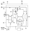
- 1 is a piping system diagram illustrating a configuration of a mixed gas supply device according to Embodiment 1.
- FIG. 6 is a cross-sectional view taken along line AA in FIG. 5. It is a flowchart which shows the procedure which adjusts the oxygen concentration in the store
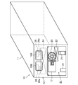
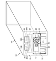
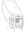
- FIG. 9 is a perspective view of the container refrigeration apparatus according to Embodiment 2 viewed from the outside of the warehouse.
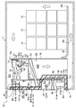
- FIG. 10 is a side cross-sectional view illustrating the configuration of the container refrigeration apparatus according to the second embodiment.
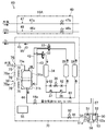
- FIG. 11 is a piping system diagram showing the configuration of the mixed gas supply apparatus according to the second embodiment.
- FIG. 12 is a perspective view illustrating an external shape of the mixed gas supply device according to the second embodiment.
- FIG. 13 is a cross-sectional view of the mixed gas supply device of Embodiment 2 as viewed from the front side.
- FIG. 9 is a perspective view of the container refrigeration apparatus according to Embodiment 2 viewed from the outside of the warehouse.
- FIG. 10 is a side cross-sectional view illustrating the configuration of the container refrigeration apparatus according to the second embodiment.
- FIG. 11 is a piping system diagram showing the configuration of the mixed gas supply apparatus according to the second embodiment.
- FIG. 12 is a perspective view illustrating an external shape of the mixed gas supply device according
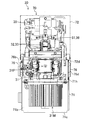
- FIG. 14 is a plan view showing a device arrangement inside the mixed gas supply apparatus of Embodiment 2 by a solid line.
- FIG. 15 is a right side view showing a device arrangement inside the mixed gas supply apparatus of Embodiment 2 with a solid line.
- FIG. 16 is a front perspective view showing the device arrangement inside the mixed gas supply device of Embodiment 2 with a solid line.
- FIG. 17 is a rear perspective view showing a device arrangement inside the mixed gas supply apparatus of Embodiment 2 by a solid line.
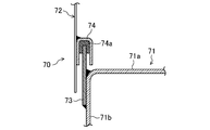
- FIG. 18 is a cross-sectional view showing a mounting structure of a base and cover of a unit case according to the second embodiment.
- FIG. 19 is a cross-sectional view showing a structure for attaching an air pump motor to the base of the unit case of the second embodiment.
- FIG. 20 is a cross-sectional view of the mixed gas supply apparatus according to the third embodiment as viewed from the front side.
- FIG. 21 is a right side view showing a device arrangement inside the mixed gas supply apparatus of Embodiment 3 with a solid line.
- FIG. 22 is a perspective view of the container refrigeration apparatus of Embodiment 4 as viewed from the outside of the warehouse.
- FIG. 23 is a side cross-sectional view illustrating the configuration of the container refrigeration apparatus according to the fourth embodiment.
- FIG. 24 is a piping diagram illustrating the configuration of the mixed gas supply device according to the fourth embodiment.
- FIG. 25 is a perspective view showing an external shape of the mixed gas supply apparatus according to the fourth embodiment.
- FIG. 26 is a front view showing a device arrangement inside the unit case of Embodiment 4 with a solid line.
- FIG. 27 is a plan view showing a device arrangement inside the unit case of Embodiment 4 with a solid line.
- FIG. 28 is a left side view showing the arrangement of devices inside the unit case of Embodiment 4 with a solid line.
- FIG. 29 is a front perspective view showing a device arrangement inside the unit case of Embodiment 4 with a solid line.
- FIG. 30 is a rear perspective view showing the arrangement of devices inside the unit case of Embodiment 4 with solid lines.
- Embodiment 1 The first embodiment will be described.
- the container refrigeration apparatus (10) of the present embodiment includes a mixed gas supply apparatus (30).
- the container refrigeration apparatus (10) cools the internal air of the container (11) used for marine transportation or the like.
- the container refrigeration apparatus (10) includes a refrigerant circuit (20) that performs a refrigeration cycle to cool the air in the container (11) (see FIG. 3).
- the plants (15) are stored in a boxed state.
- the plant (15) breathes by taking in oxygen (O 2 ) in the air and releasing carbon dioxide (CO 2 ).
- O 2 oxygen
- CO 2 carbon dioxide
- fruits and vegetables such as banana and avocado, vegetables, grains, bulbs, fresh flowers, etc. It is.
- the container (11) is formed in an elongated box shape with one end face opened.
- the container refrigeration apparatus (10) is attached so as to close one open end of the container (11).
- the casing (12) of the container refrigeration apparatus (10) includes a warehouse outer wall (12a) located outside the container (11) and a cabinet inner wall (12b) located inside the container (11). Yes.
- the outer wall (12a) and the inner wall (12b) are made of, for example, an aluminum alloy.
- the outer wall (12a) is attached to the peripheral edge of the opening of the container (11) so as to close the opening end of the container (11).
- the warehouse outer wall (12a) is formed so that the lower part bulges to the inside of the container (11).
- the inner wall (12b) is disposed opposite the outer wall (12a).
- the inner wall (12b) bulges to the inner side corresponding to the lower part of the outer wall (12a).
- a heat insulating material (12c) is provided in the space between the inner wall (12b) and the outer wall (12a).
- the lower part of the casing (12) is formed so as to bulge toward the inner side of the container (11).
- an outside storage space (S1) is formed outside the container (11) at the lower part of the casing (12), and an inside storage space is provided inside the container (11) at the upper part of the casing (12). (S2) is formed.
- the casing (12) is provided with two service doors (16A, 16B) that can be opened and closed during maintenance, arranged side by side in the width direction.
- an electrical component box (17) is disposed at a position adjacent to an external fan (25) described later.
- the partition plate (18) is arranged inside the container (11).
- This partition plate (18) is comprised by the substantially rectangular-shaped board member, and is standingly arranged in the attitude
- the partition plate (18) divides the interior of the container (11) from the interior storage space (S2).
- a suction port (18a) is formed between the upper end of the partition plate (18) and the ceiling surface in the container (11). The air in the container (11) is taken into the storage space (S2) through the suction port (18a).
- a partition wall (13) extending in the horizontal direction is provided in the storage space (S2).
- the partition wall (13) is attached to an upper end portion of the partition plate (18), and an opening in which a later-described internal fan (26) is installed is formed.
- this partition wall (13) is the storage space (S2) in the warehouse, the primary space (S21) on the suction side of the internal fan (26), and the secondary space on the outlet side of the internal fan (26). (S22).
- a floor board (19) is disposed with a gap between the bottom of the container (11).
- a boxed plant (15) is placed on the floor board (19).
- An air flow path (19a) is formed between the bottom surface in the container (11) and the floor board (19).
- a gap is provided between the lower end of the partition plate (18) and the bottom surface in the container (11), and communicates with the air flow path (19a).
- the air intake (47) for introducing outside air into the container (11) and the air in the container (11) are exhausted to the outside.
- the exhaust part (46) has an exhaust pipe (46a) connecting the inside and the outside of the container (11), and an exhaust valve (46b) connected to the exhaust pipe (46a).
- the intake part (47) includes an intake pipe (47a) that connects the inside and the outside of the container (11), and an intake valve (47b) connected to the intake pipe (47a).
- the container refrigeration apparatus (10) includes a refrigerant circuit (20) that performs a vapor compression refrigeration cycle by circulating the refrigerant.
- the refrigerant circuit (20) was configured by connecting a compressor (21), a condenser (22), an expansion valve (23), and an evaporator (24) in order by a refrigerant pipe (28). It is a closed circuit.
- the compressor (21) and the condenser (22) are stored in the external storage space (S1).
- An external fan (25) is disposed above the condenser (22).
- the outside fan (25) is rotationally driven by the outside fan motor (25a), attracts the air outside the container (11) into the outside storage space (S1), and sends it to the condenser (22).
- the condenser (22) heat exchange is performed between the refrigerant flowing inside the condenser (22) and the outside air.
- the evaporator (24) is stored in the storage space (S2).
- Two internal fans (26) are arranged side by side in the width direction of the casing (12) above the evaporator (24) in the internal storage space (S2).
- the internal fan (26) is rotationally driven by the internal fan motor (26a), draws the internal air of the container (11) from the suction port (18a), and blows it out to the evaporator (24).
- the evaporator (24) heat exchange is performed between the refrigerant flowing inside the evaporator (24) and the internal air.
- the in-compartment air that has been radiated and cooled to the refrigerant when passing through the evaporator (24) is blown out from the outlet (18b) into the container (11) through the air flow path (19a).
- the container refrigeration apparatus (10) includes a mixed gas supply device (30) for supplying a mixed gas having a low oxygen concentration into the container (11).
- the mixed gas supply device (30) of the present embodiment generates a mixed gas by VPSA (Vacuum Pressure Swing Adsorption).
- the mixed gas supply device (30) includes an air pump (31), a first direction control valve (32) and a second direction control valve (33), and adsorbs nitrogen in the air.
- a first adsorption cylinder (34) and a second adsorption cylinder (35) provided with an adsorbent, a purge valve (36), a first check valve (37) and a second check valve (38), oxygen; And a tank (39).
- the air pump (31) is disposed in the external storage space (S1).
- the air pump (31) includes a pressurization unit (31a) and a decompression unit (31b).
- the pressurization part (31a) of the air pump (31) sucks and compresses the outside air through the inflow passage (41) connected to the outside of the container (11).
- the pressurizing section (31a) supplies compressed air to the first adsorption cylinder (34) and the second adsorption cylinder (35) through the outflow passage (42) to pressurize the nitrogen in the air.
- Adsorption operation to adsorb to the adsorbent is performed.
- An air filter (41a) is attached in the middle of the inflow passage (41).
- the decompression section (31b) of the air pump (31) sucks air from the first adsorption cylinder (34) and the second adsorption cylinder (35) via the suction passage (43) and depressurizes it, thereby reducing nitrogen from the adsorbent. Desorption operation to desorb is performed.
- the depressurization section (31b) depressurizes the internal pressure of the first adsorption cylinder (34) and the second adsorption cylinder (35) to a negative pressure (that is, a pressure lower than the atmospheric pressure) during the desorption operation.
- a negative pressure that is, a pressure lower than the atmospheric pressure
- the pressurization part (31a) and the decompression part (31b) of the air pump (31) are constituted by oilless pumps that do not use lubricating oil.
- the pressurizing unit (31a) is an air compressor that compresses the sucked air to a pressure higher than the atmospheric pressure and discharges the compressed air to the supply destination.
- the decompression unit (31b) is an exhaust pump that sucks and discharges air from the connection destination.
- a blower fan (48) for cooling the air pump (31) by blowing air toward the air pump (31) is disposed above the air pump (31).
- the first directional control valve (32) and the second directional control valve (33) are for alternately switching the first adsorption cylinder (34) and the second adsorption cylinder (35) that are the targets of the adsorption operation and the desorption operation. It is.
- the first direction control valve (32) is connected to the discharge port of the pressurization unit (31a), the suction port of the decompression unit (31b), and the top of the first adsorption cylinder (34).
- the first directional control valve (32) includes a state in which the first adsorption cylinder (34) communicates with the pressurization unit (31a) and is shut off from the decompression unit (31b) (the state shown in FIG. 4), and the first adsorption control valve (32).
- the cylinder (34) communicates with the decompression section (31b) and switches to a state where the cylinder (34) is blocked from the pressurization section (31a).
- the second directional control valve (33) is connected to the discharge port of the pressurization unit (31a), the suction port of the decompression unit (31b), and the top of the second adsorption cylinder (35).
- the second directional control valve (33) communicates the second adsorption cylinder (35) with the pressurization section (31a) and is disconnected from the decompression section (31b), and the second adsorption cylinder (35) is a decompression section.
- the state is switched to a state (the state shown in FIG. 4) that is communicated with (31b) and is cut off from the pressurizing portion (31a).
- the pressurizing unit (31a) performs an adsorption operation for the first adsorption cylinder (34), and the decompression unit (31b) performs the desorption operation for the second adsorption cylinder (35).
- the pressurizing part (31a) is the second adsorption cylinder.
- the adsorption operation targeting (35) is performed, and the decompression section (31b) performs the desorption operation targeting the first adsorption cylinder (34).
- the mixed gas supply device (30) continuously repeats the above steps while alternately switching the first adsorption cylinder (34) and the second adsorption cylinder (35) that are the targets of the adsorption operation and the desorption operation. A stable gas mixture. This switching operation is controlled by the control unit (55).
- the first adsorbing cylinder (34) and the second adsorbing cylinder (35) are cylindrical members filled with an adsorbent inside, and in an upright posture (that is, an posture in which the respective axial directions are vertical directions). is set up.
- the first adsorption cylinder (34) and the second adsorption cylinder (35) adsorb nitrogen in the compressed air supplied from the pressurization part (31a) of the air pump (31) to generate oxygen-enriched air.
- the adsorbent filled in the first adsorption cylinder (34) and the second adsorption cylinder (35) adsorbs nitrogen in a state where the adsorption cylinder (34, 35) is pressurized, and the adsorption cylinder (34, 35). Has a property of desorbing nitrogen under reduced pressure.
- the adsorbent filled in the first adsorption cylinder (34) and the second adsorption cylinder (35) is, for example, smaller than the molecular diameter of nitrogen molecules (3.0 angstroms) and the molecular diameter of oxygen molecules (2.8 angstroms). ) And a porous zeolite having pores with a larger pore diameter than the above. If zeolite having such a pore size is used as an adsorbent, nitrogen in the air can be adsorbed.
- zeolite has the property of adsorbing polar molecules such as water molecules. Therefore, not only nitrogen in the air but also moisture (water vapor) in the air is adsorbed to the adsorbent made of zeolite filled in the first adsorption cylinder (34) and the second adsorption cylinder (35). The water adsorbed on the adsorbent is desorbed from the adsorbent together with nitrogen by the desorption operation. For this reason, the mixed gas containing moisture is supplied into the container (11), and the humidity in the container can be increased. Furthermore, since the adsorbent is regenerated, the life of the adsorbent can be extended.
- the nitrogen adsorbed by the adsorbent is desorbed.
- nitrogen-enriched air that is, a mixed gas having a lower oxygen concentration by containing more nitrogen than the outside air
- the mixed gas has a nitrogen concentration of 90% and an oxygen concentration of 10%.
- the pressurization pressure of the air pump is set to a relatively high value (for example, about 827.6 kPa). Yes.
- the mixed gas supply device (30) of the present embodiment it is only necessary to generate a mixed gas having a nitrogen concentration of 90% and an oxygen concentration of 10%. Therefore, the pressure of the air pump (31) is relatively low. Setting to a value (for example, about 150 kPa) is sufficient. Therefore, in the mixed gas supply device (30) of the present embodiment, it is not necessary to set the pressurizing pressure of the air pump (31) to a high pressure as in the past, and as a result, the pressurizing unit (31a) can be downsized. Can do.
- the pressure reduction part (31b) for desorbing nitrogen from an adsorbent is needed separately.
- the decompression unit (31b) can also be reduced in size. That is, as a whole apparatus, compared with the conventional apparatus provided with a large-sized air compressor, the air pump (31) having a small pressurizing part (31a) and a small decompressing part (31b) of the present embodiment is provided.
- the mixed gas supply device (30) has a lower weight.
- the mixed gas is supplied into the container (11) through a mixed gas supply passage (44) as a supply unit.
- the mixed gas supply passage (44) is provided with a check valve (44a).
- the lower ends of the first adsorption cylinder (34) and the second adsorption cylinder (35) (the outlet at the time of pressurization and the inlet at the time of decompression) are connected to the first check valve (37) and the second 2 It communicates with the oxygen tank (39) via the check valve (38).
- the oxygen tank (39) temporarily stores the oxygen-enriched air generated in the first adsorption cylinder (34) and the second adsorption cylinder (35).
- the outlet of the oxygen tank (39) is connected to an oxygen discharge passage (45) connected to the outside of the container (11).
- the oxygen discharge passage (45) is provided with an orifice (61) and a check valve (45a).
- the oxygen-enriched air stored in the oxygen tank (39) is depressurized by the orifice (61) and then discharged out of the container (11) through the oxygen discharge passage (45).
- the first adsorption cylinder (34), the second adsorption cylinder (35), and the oxygen tank (39) are disposed in the vicinity of the evaporator (24) in the storage space (S2). Specifically, as shown in FIGS. 5 and 6, the first adsorption cylinder (34), the second adsorption cylinder (() in a state where it stands in the gap between the side wall of the container (11) and the evaporator (24). 35) and the oxygen tank (39) are arranged in the depth direction of the container (11).
- the lower ends of the first adsorption cylinder (34) and the second adsorption cylinder (35) communicate with each other via a purge valve (36).
- the piping between the lower end portion of the first adsorption cylinder (34) and the purge valve (36) and the piping between the lower end portion of the second adsorption cylinder (35) and the purge valve (36) include an orifice (62 ) Are attached.
- the purge valve (36) supplies a predetermined amount of oxygen-enriched air from the pressure-side adsorption cylinder (first adsorption cylinder (34) in FIG. 4) to the pressure-reduction side adsorption cylinder (second adsorption cylinder (35) in FIG. 4). It is used to guide and assist in releasing nitrogen from the adsorbent of the adsorption cylinder on the decompression side.
- the opening / closing operation of the purge valve (36) is controlled by the control unit (55).
- the mixed gas supply device (30) includes a first operation in which the second adsorption cylinder (35) is depressurized at the same time as the first adsorption cylinder (34) is pressurized, and the first adsorption cylinder (34) is depressurized. At the same time, the second operation in which the second adsorption cylinder (35) is pressurized is repeated alternately for a predetermined time (for example, 15 seconds). Switching between the first operation and the second operation is performed by the controller (55) operating the first direction control valve (32) and the second direction control valve (33).
- the pressurizing unit (31a) performs an adsorption operation for the first adsorption cylinder (34), and the decompression unit (31b) performs a desorption operation for the second adsorption cylinder (35). That is, in the mixed gas supply device (30) in the first operation, the pressurizing unit (31a) supplies air to the first adsorption cylinder (34) and at the same time the decompression unit (31b) is supplied from the second adsorption cylinder (35). The first operating state for sucking air is entered.
- the first directional control valve (32) and the second directional control valve (33) are set to the state shown in FIG. That is, the first directional control valve (32) is in a state where the first adsorption cylinder (34) communicates with the pressurizing unit (31a) and is shut off from the depressurizing unit (31b). The second directional control valve (33) Then, the second adsorption cylinder (35) is brought into communication with the pressure reducing part (31b) and is shut off from the pressure applying part (31a).
- the pressurizing unit (31a) supplies pressurized outside air to the first adsorption cylinder (34). Nitrogen contained in the air flowing into the first adsorption cylinder (34) is adsorbed by the adsorbent in the first adsorption cylinder (34). Air deprived of nitrogen by the adsorbent in the first adsorption cylinder (34) (that is, oxygen-enriched air having an oxygen concentration higher than the outside air) flows out of the first adsorption cylinder (34), and the first check valve ( 37) and oxygen tank (39) are passed through in order, and then discharged outside the warehouse.
- Nitrogen contained in the air flowing into the first adsorption cylinder (34) is adsorbed by the adsorbent in the first adsorption cylinder (34). Air deprived of nitrogen by the adsorbent in the first adsorption cylinder (34) (that is, oxygen-enriched air having an oxygen concentration higher than the outside air) flows out of the first adsorption cylinder (34), and the first check valve (
- the decompression section (31b) sucks air from the second adsorption cylinder (35). At that time, nitrogen is desorbed from the adsorbent of the second adsorption cylinder (35). For this reason, the decompression unit (31b) sucks air containing nitrogen (that is, a mixed gas that is nitrogen-enriched air having a higher nitrogen concentration than the outside air) from the adsorbent of the second adsorption cylinder (35).
- the mixed gas sucked into the decompression section (31b) from the second adsorption cylinder (35) is discharged from the decompression section (31b) and then flows through the mixed gas supply passage (44) and is supplied into the warehouse.
- the pressurizing unit (31a) performs an adsorption operation for the second adsorption cylinder (35), and the decompression unit (31b) performs a desorption operation for the first adsorption cylinder (34). That is, in the mixed gas supply device (30) in the second operation, the pressurizing unit (31a) supplies air to the second adsorption cylinder (35) and at the same time the decompression unit (31b) is supplied from the first adsorption cylinder (34). The second operating state for sucking air is entered.
- the first directional control valve (32) and the second directional control valve (33) are set on the opposite side to the state shown in FIG. That is, the first directional control valve (32) is in a state where the first adsorption cylinder (34) communicates with the pressure reducing part (31b) and is cut off from the pressure applying part (31a), and the second directional control valve (33) is Then, the second adsorption cylinder (35) is brought into communication with the pressurizing part (31a) to be shut off from the decompression part (31b).
- the pressurizing unit (31a) supplies pressurized outside air to the second adsorption cylinder (35). Nitrogen contained in the air flowing into the second adsorption cylinder (35) is adsorbed by the adsorbent of the second adsorption cylinder (35). Air deprived of nitrogen by the adsorbent of the second adsorption cylinder (35) (that is, oxygen-enriched air whose oxygen concentration is higher than the outside air) flows out of the second adsorption cylinder (35), and the second check valve ( 38) and oxygen tank (39) are passed through in order, and then discharged outside the warehouse.
- Nitrogen contained in the air flowing into the second adsorption cylinder (35) is adsorbed by the adsorbent of the second adsorption cylinder (35). Air deprived of nitrogen by the adsorbent of the second adsorption cylinder (35) (that is, oxygen-enriched air whose oxygen concentration is higher than the outside air) flows out of the second adsorption cylinder (35), and the second check
- the decompression section (31b) sucks air from the first adsorption cylinder (34). At that time, nitrogen is desorbed from the adsorbent of the first adsorption cylinder (34). For this reason, the decompression unit (31b) sucks air containing nitrogen (that is, a mixed gas that is nitrogen-enriched air having a higher nitrogen concentration than the outside air) from the adsorbent of the first adsorption cylinder (34).
- the mixed gas sucked into the decompression section (31b) from the first adsorption cylinder (34) is discharged from the decompression section (31b) and then flows through the mixed gas supply passage (44) and is supplied into the warehouse.
- the control unit (55) performs an operation of adjusting the oxygen concentration and the carbon dioxide concentration in the warehouse based on the detection result of the oxygen concentration detection sensor (51) and the detection result of the carbon dioxide concentration detection sensor (52).
- operation movement of this control part (55) is demonstrated.
- FIG. 7 is a flowchart showing a procedure for adjusting the oxygen concentration in the container.
- the control unit (55) determines whether the oxygen concentration detected by the oxygen concentration detection sensor (51) is higher than the oxygen concentration (oxygen 10%) of the mixed gas. To do. If the determination in step S101 is “YES” (oxygen concentration> 10%), the control unit (55) proceeds to step S102. When the determination in step S101 is “NO” (when the oxygen concentration ⁇ 10%), the control unit (55) proceeds to step S105.
- step S102 the control unit (55) causes the mixed gas supply device (30) to supply the mixed gas (nitrogen 90%, oxygen 10%) into the container (11). Thereafter, the control unit (55) proceeds to step S103.
- step S103 the control unit (55) determines whether the oxygen concentration detected by the oxygen concentration detection sensor (51) has dropped below the oxygen concentration (oxygen 10%) of the mixed gas.
- the determination in step S103 is “YES” (when the oxygen concentration ⁇ 10%)
- the control unit (55) proceeds to step S104.
- the determination in step S103 is “NO” (when the oxygen concentration> 10%)
- the control unit (55) stands by.
- step S104 the control unit (55) causes the mixed gas supply device (30) to stop supplying the mixed gas.
- the plant (15) stored therein breathes. That is, in the storage of the container (11), oxygen contained in the storage air is taken into the plant (15), and carbon dioxide generated by the respiration of the plant (15) is released into the storage. For this reason, in the state which the supply operation of the mixed gas from the mixed gas supply apparatus (30) to the store
- step S105 the control unit (55) determines whether the oxygen concentration detected by the oxygen concentration detection sensor (51) is lower than the target concentration (5%).
- the target concentration of oxygen is 5%.
- the target concentration is 3%. preferable.
- step S105 When the determination in step S105 is “YES” (when the oxygen concentration is less than 5%), the control unit (55) proceeds to step S106. When the determination in step S105 is “NO” (when the oxygen concentration ⁇ 5%), the control unit (55) stands by.
- step S106 the control unit (55) causes the mixed gas supply device (30) to supply the mixed gas (nitrogen 90%, oxygen 10%) into the container (11) or the intake unit (47). Supply outside air into the container (11). Thereafter, the above-described processing is repeated from the beginning.
- step S106 the supply of the mixed gas by the mixed gas supply device (30) and the supply of the outside air by the intake section (47) may be performed simultaneously.
- FIG. 8 is a flowchart showing a procedure for adjusting the carbon dioxide concentration in the container.
- the control unit (55) determines whether the carbon dioxide concentration detected by the carbon dioxide concentration detection sensor (52) is higher than a predetermined target concentration (5%). To do.
- a predetermined target concentration 5%
- the target concentration of carbon dioxide is 5%.
- the target concentration is 10%. Is preferred.
- step S201 When the determination in step S201 is “YES” (when the carbon dioxide concentration> 5%), the control unit (55) proceeds to step S202. When the determination in step S201 is “NO” (when the carbon dioxide concentration ⁇ 5%), the control unit (55) stands by.
- step S202 the control unit (55) causes the mixed gas supply device (30) to supply the mixed gas (nitrogen 90%, oxygen 10%) into the container (11), or causes the exhaust unit (46) to supply the mixed gas.
- the air inside the container (11) is exhausted to the outside.
- step S202 the supply of the mixed gas by the mixed gas supply device (30) and the exhaust of the internal air by the exhaust part (46) may be performed simultaneously.
- step S203 the control unit (55) determines whether the carbon dioxide concentration detected by the carbon dioxide concentration detection sensor (52) has fallen below the target concentration.
- the determination in step S203 is “YES” (when the carbon dioxide concentration ⁇ 5%)
- the control unit (55) proceeds to step S204.
- the determination in step S203 is “NO” (when the carbon dioxide concentration> 5%)
- the control unit (55) stands by.
- step S204 the control unit (55) stops the supply of the mixed gas by the mixed gas supply device (30) or stops the exhaust of the internal air by the exhaust unit (46). Thereafter, the control unit (55) repeats the above-described processing from the beginning.
- the container refrigeration apparatus (10) of the present embodiment uses, for example, an adsorbent that adsorbs nitrogen in order to generate a mixed gas having a nitrogen concentration of 90% and an oxygen concentration of 10%. For this reason, it is not necessary to set the pressurizing pressure of the pressurizing part (31a) of the air pump (31) to a very high pressure. Therefore, according to this embodiment, the pressurizing part (31a) can be reduced in size. Further, when desorbing nitrogen from the adsorbent, it is not necessary to reduce the pressure of the adsorption cylinder (34, 35) so much, so the pressure reducing part (31b) of the air pump (31) can also be reduced in size. Therefore, according to this embodiment, the mixed gas supply device (30) can be miniaturized using a small air pump (31), and further, the weight of the container refrigeration device (10) can be reduced and the cost can be reduced. it can.
- the adsorbents of the first adsorption cylinder (34) and the second adsorption cylinder (35) have a characteristic that the adsorbability increases as the ambient temperature decreases.
- the first adsorption cylinder (34) and the second adsorption cylinder (35) are disposed near the evaporator (24) in the storage space (S2). ing. For this reason, by keeping the temperature of the adsorbent of the first adsorption cylinder (34) and the second adsorption cylinder (35) low, the adsorption performance of the adsorbent can be improved and nitrogen in the air can be easily adsorbed. .
- the container refrigeration apparatus (10) of the present embodiment moisture is adsorbed by the adsorbent together with nitrogen in the air during the adsorption operation, and the moisture adsorbed by the adsorbent is desorbed from the adsorbent together with nitrogen during the desorption operation. Therefore, in the container refrigeration apparatus (10) of the present embodiment, the mixed gas containing moisture is supplied into the container (11), and the humidity inside the container can be increased. Furthermore, it is possible to extend the life of the adsorbent by regenerating the adsorbent.
- the pressurizing unit (31a) and the decompressing unit (31b) are constituted by an oilless pump, when lubricating oil is used for the pump, The trouble which arises can be eliminated. Specifically, the oil contained in the compressed air is adsorbed by the adsorbent and the adsorption performance of the adsorbent is reduced, and the oil odor is generated against the inside of the container (11) loaded with plants (15). This eliminates the problem of supplying the mixed gas.
- the container refrigeration apparatus (10) of the present embodiment includes a mixed gas supply apparatus (30), similar to the container refrigeration apparatus (10) of the first embodiment.
- the container refrigeration apparatus (10) of the present embodiment is obtained by changing the configuration of the mixed gas supply apparatus (30) in the container refrigeration apparatus (10) of the first embodiment.
- the difference between the mixed gas supply device (30) of the present embodiment and the mixed gas supply device (30) of the first embodiment will be described.
- the mixed gas supply device (30) of the present embodiment includes an air pump (31), a first directional control valve (32), and a second directional control valve (33). ), A first adsorption cylinder (34) and a second adsorption cylinder (35) provided with an adsorbent for adsorbing nitrogen in the air, a purge valve (36), and a first check valve (37) And a second check valve (38) and an oxygen tank (39) (see FIG. 11).
- the mixed gas supply device (30) of the present embodiment constitutes one unit by storing these components in the unit case (70).
- the mixed gas supply device (30) of the present embodiment is installed in the external storage space (S1).
- the mixed gas supply device (30) is configured to be retrofitted to the main body of the container refrigeration apparatus (10). Details of the structure of the mixed gas supply device (30) will be described later.
- the air pump (31) is disposed in the unit case (70).
- the air pump (31) sucks and compresses the outside air flowing from the outside of the unit case (70) through the air inlet (75) formed in the unit case (70).
- the unit case (70) is a box-shaped member.
- the unit case (70) includes a base (71) and a cover (72).
- the base (71) includes a support plate (71a) that supports equipment inside the mixed gas supply device (30), and leg plates that extend downward from the left and right ends of the support plate (71a).
- 71b) and a mounting plate (71c) extending inwardly of the base (71) from the lower end of each leg plate (71b).
- the support plate (71a), the leg plate (71b), and the mounting plate (71c) are formed by bending a single metal plate.
- the back surface of the base (71) is provided with a ventilation plate (71d) in which a plurality of parallel slits (71e) extending from side to side are formed vertically.
- the cover (72) has four side plates (72a) and a top plate (72b) that closes the upper end of each side plate (72a).
- the cover (72) has a lower end attached to the upper end of the base (71), and the attachment part has an airtight waterproof structure.
- the support plate (73) is fixed to the entire periphery of the upper end of the base, and the sealing material (74a) is held to the entire inner periphery of the lower end of the cover (72).
- a unit is provided by tightening the base (71) and the cover (72) with a fastening member such as a bolt while the seal holding part (74) is provided and the sealing material (74a) is fitted in the support plate (73).
- the case (70) has an integral structure. In the unit case (70) having an integral structure, a space enclosed by the support plate (71a) of the base (71) and the cover (72) is a device storage space having an airtight waterproof structure.
- the right side surface of FIG. 12 in the unit case (70) is provided with a membrane filter (76) having air permeability and waterproofness.
- a membrane filter (76) having air permeability and waterproofness.
- an air inflow port (75) for the air pump (31) to suck air into the unit case (70) is formed as shown in FIG. 11, and the membrane filter (76)
- the unit case (70) is attached to the air inlet (75). Since the membrane filter (76) has air permeability as described above, when the air pump (31) is activated, it is possible to suck air into the unit case (70) via the membrane filter (76). On the other hand, since the membrane filter (76) is waterproof and moisture does not pass through, the moisture does not enter the unit case (70).
- the membrane filter (76) for example, a vent filter manufactured by Nippon Gore Co., Ltd. can be used.
- the membrane filter (76) includes a flat plastic cap (76a) and a membrane-like filter member (not shown) mounted inside the cap (76a).
- the cap (76a) has a substantially regular hexagonal shape, and an air vent (not shown) is formed on the outer peripheral surface (76b), and the air flows from the outer peripheral surface into the cap (76a). Passes through the filter member.
- the filter member captures dust contained in the air. Most of the trapped dust adheres to the outer peripheral surface of the cap (76a). And the dust adhering to the outer peripheral surface of the said cap (76a) is removed from a cap (76a) under the influence of the airflow of the external space of a container (11).
- a device storage space for storing the components of the mixed gas supply device (30) is formed inside the unit case (70) configured by assembling the base (71) and the cover (72) together.
- the unit case (70) has a pump mechanism (31P) of the air pump (31), the first directional control valve (32) and the second directional control valve ( 33), the first adsorption cylinder (34) and the second adsorption cylinder (35), the purge valve (36), the first check valve (37) and the second check valve (38), Parts such as the oxygen tank (39) are provided.
- each component in the unit case (70) is pipe-connected according to the piping system diagram of FIG.
- a cover (72) of the unit case (70) has an outlet for mixed gas (nitrogen-enriched air) and an outlet for oxygen-enriched air.
- the air pump (31) is arranged at a position near the right end of the space in the unit case (70) in FIGS. Further, the first suction cylinder (34) and the second suction cylinder (35) are arranged at positions near the left end of the space in the unit case (70) in FIGS.
- the air pump (31) includes a pump mechanism (31P) and a motor (31M).
- the pump mechanism section (31P) constitutes a pressurizing section (31a) and a decompression section (31b). Similar to the first embodiment, the pressurizing unit (31a) supplies the sucked and compressed air to the adsorption cylinder (34, 35) through the outflow passage (42).
- the pressurizing unit (31a) sucks air from the inlet (31s) and discharges it from the outlet (31d).
- the decompression section (31b) sucks air (nitrogen-enriched air) from the adsorption cylinder (34, 35) through the outflow passage (42), and the sucked air is mixed gas supply passage (44 ).
- the motor (31M) of the air pump (31) is mounted on the unit case (70) so as to protrude downward from the lower surface of the base (71). What is necessary is just to provide the said motor (31M) so that at least one part may be located in the outer side of the said unit case (70).
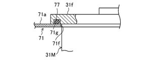
- the motor (31M) has a flange (mounting portion) (31f) of the motor (31M) and a fastening member such as a bolt (not shown) on the support plate (71a) of the base (71). It is configured to be attached with. Specifically, the motor (31M) main body (cylindrical portion below the flange (31f)) is passed from the top through the motor mounting hole (71f) of the support plate (71a), and the lower surface of the flange (31f) is A bolt or the like is tightened while being in contact with the support plate (71a) and fixed to the support plate (71a).
- a seal groove (71g) is formed on the lower surface of the flange (31f), and an O-ring (77) (seal member) is attached to the seal groove (71g), so the support plate (71a) and the flange ( 31f) is airtight and waterproof.
- the structure in which the O-ring (77) as the seal member is provided between the flange (31f) as the mounting portion of the motor (31M) and the support plate (71a) of the unit case (70) as described above. 70) Seal structure.
- the mixed gas supply device (30) of the present embodiment includes a first adsorption cylinder (34) and a second adsorption cylinder (35) provided with an adsorbent that adsorbs and desorbs nitrogen in the air. This is the same as the mixed gas supply device (30) of the first embodiment.
- the pressurization unit (31a) of the pump mechanism unit (31P) has the suction port (31s) opened and the outflow port (31d) in the first direction. It is connected to the first adsorption cylinder (34) and the second adsorption cylinder (35) via the control valve (32) and the second directional control valve (33).
- the unit case (70) of the present embodiment has a first adsorption cylinder (34) and a second adsorption cylinder in addition to an air inlet (75) for supplying air to the air pump (31).
- An outflow port (not shown) for sending out a mixed gas (nitrogen-enriched air) containing nitrogen from (35) is provided.
- a first directional control valve (32) and a second directional control valve (33) are provided in the unit case.
- the mixed gas supply apparatus (30) of this embodiment is the said in the air flow in which the said motor (31M) passes the condenser (22) which is an external heat exchanger of the said container refrigeration apparatus (10). Arranged upstream of the condenser (22).
- the motor (31M) is on the upstream side of the above air flow when the external fan (25) is activated and the outside air condenses after passing around the equipment located in the lower part of the external storage space (S1) This is because after passing through the vessel, it is blown out of the outside fan (25).
- the motor (31M) is disposed near the right end of the mixed gas supply device (30). Therefore, with the mixed gas supply device (30) attached to the container refrigeration device (10), the motor (31M) is located near the outside fan (25) as a component of the mixed gas supply device (30). . Therefore, the airflow generated by the external fan (25) is likely to flow around the motor (31M). The outside air that has passed through the motor (31M) flows to the condenser (22) through the slit (71e) of the ventilation plate (71d).
- the mixed gas supply device (30) of the present embodiment is configured as described above, it can be retrofitted to the outside storage space (S1) of the container refrigeration device (10). May connect a pipe for supplying the mixed gas (nitrogen-enriched air) into the container (11) between the mixed gas supply device (30) and the container (11).
- the electrical component module (78) in which the control board and the like are accommodated is disposed behind the pump mechanism (31P) in the unit case (70).
- measures against noise are taken by adopting a box structure in which a control board or the like is surrounded by sheet metal parts.
- the mixed gas supply device (30) having the above-described configuration is disposed in the lower left corner of the external storage space (S1) as shown in FIG.
- the inverter box (29) that houses a drive circuit for driving the compressor (21) at a variable speed is arranged on the right side of the mixed gas supply device (30).
- the calorific value of the inverter box (29) is larger.
- the mixed gas supply device (30) is located upstream of the inverter box (29) in the airflow.
- the mixed gas supply device (30) of the present embodiment repeats the first operation and the second operation alternately, so that the nitrogen concentration is higher than that of the outside air. A mixed gas that is concentrated air is produced. Further, in the container refrigeration apparatus (10) of the present embodiment, the control unit (55) performs an operation of adjusting the oxygen concentration and the carbon dioxide concentration in the warehouse, as in the first embodiment.
- the mixed gas supply device (30) is provided by housing components such as the pump mechanism (31P) and the adsorption cylinder (34, 35) of the air pump (31) in the unit case (70). Since it is a single unit, the mixed gas supply device (30) can be retrofitted to the container refrigeration device (10). Therefore, even if it is a container refrigeration system provided in an existing container, if this unit type mixed gas supply device (30) is installed, the mixed gas (nitrogen-enriched air) can be supplied into the container. This makes it possible to adjust the oxygen concentration in the container. Moreover, since the mixed gas supply device (30) is unitized, when a failure occurs in the mixed gas supply device (30), the unit can be easily replaced.
- the mixed gas supply device (30) of the present embodiment is a unit in which components are incorporated in a unit case (70) of a unitary integrated structure, and a membrane filter (76) is attached to the unit case (70).
- the structure is both waterproof and breathable. Therefore, since the temperature difference between the inside and outside of the unit case (70) is less likely to occur even in an environment where the outside air temperature fluctuates greatly, condensation is unlikely to occur in the unit case (70), and there is little risk of electrical component insulation failure.
- the unit case (70) since the unit case (70) is not airtight, it is difficult for moisture to enter through the gap between the unit case (70) due to the capillary phenomenon due to the pressure difference between the inside and outside, and there is little risk of electrical component insulation failure. .
- the unit case (70) since the unit case (70) is waterproof, it is possible to suppress corrosion of the electrical components and metal parts inside the unit case (70) due to salt damage due to the offshore atmosphere.
- the membrane filter (76) is not the upper surface of the unit case (70). Since it is provided on the side surface, dust is easily detached from the membrane filter (76) due to vibration of the mixed gas supply device (30) when the container (11) is transferred. Therefore, the maintainability of the membrane filter (76) is improved.
- the motor (31M) of the air pump (31), which is a heat generating part, is configured to be located outside the unit case (70), and this motor (31M) Because it is cooled by the airflow, the operation of the motor (31M) can be stabilized and the motor (31M) is placed in the unit case (70) and a dedicated cooling blower is provided. Compared to parts and costs. Also, when the motor (31M) is housed inside the unit case (70), the heat generated by the motor (31M) may affect other components, which may reduce the reliability of the gas mixture supply device (30). However, in this embodiment, since the motor (31M) is arranged outside the unit case (70), the reliability of the mixed gas supply device (30) is not lowered.
- the motor (31M) is configured to be located outside the unit case (70), but the flange (31f) of the motor (31M) is connected to the unit via an O-ring (77) as a seal member. Since it is attached to the case (70), it is possible to prevent the waterproof performance of the mixed gas supply device (30) from being lowered.
- Embodiment 3 A third embodiment will be described.
- the container refrigeration apparatus (10) of the present embodiment is different from the container refrigeration apparatus (10) of the second embodiment in the mounting structure of the pump mechanism (31P) and the motor (31M) in the mixed gas supply device (30). It is a thing. Here, the difference from Embodiment 2 is demonstrated about the mixed gas supply apparatus (30) of this embodiment.
- the pump mechanism (31P) is positioned above the support plate (71a) of the unit case (70). Has been placed. Therefore, the pump mechanism part (31P) has a bracket (80) attached to the upper surface of the support plate (71a) and is fixed to the upper end of the bracket (80).
- the motor (31M) is attached to the lower surface of the support plate (71a) via a seal member (not shown) such as an O-ring. Then, the output shaft (81) of the motor (31M) and the drive shaft (82) of the pump mechanism (31P) are arranged to face each other on the same axis, and these shafts (81, 82) are coupled ( 83). As a result, when the motor (31M) rotates, the pump mechanism (31P) is driven, so that air sucked into the unit case (70) from the membrane filter (76) is sucked into the pump mechanism (31P). And used to produce a mixed gas (nitrogen-enriched air).
- a mixed gas nitrogen-enriched air
- the motor (31M) which is a heat generating part, is arranged so as to come out of the unit case (70).
- Equipment such as a dedicated blower for cooling is unnecessary. Therefore, the cost and the number of parts can be reduced, and the reliability of the motor heat dissipation structure can be improved.
- the motor (31M) and the shaft (81, 82) of the pump mechanism (31P) are coupled to each other by a coupling (83), and the motor ( 31M) is fixed to the lower surface of the support plate (71a) of the unit case (70) via an O-ring, so that the sealing performance of the portion where the motor (31M) is attached can be secured. Therefore, the waterproof performance of the unit case (70) can be secured.
- the present embodiment can achieve the same effects as those of the second embodiment.
- the container refrigeration apparatus (10) of the present embodiment includes a mixed gas supply apparatus (30), similar to the container refrigeration apparatus (10) of the second embodiment.
- the difference between the container refrigeration apparatus (10) of the present embodiment and the container refrigeration apparatus (10) of the second embodiment will be mainly described.
- the mixed gas supply apparatus (30) includes a service door unit (40), a sensor unit (50), a measurement unit (80), and a control unit (55), as well as a CA. It constitutes a device (Controlled Atmosphere System) (60). As for the mixed gas supply device (30), the service door unit (40) and the sensor unit (50) will be described later.
- the control unit (55) is configured to adjust the oxygen concentration and the carbon dioxide concentration of the internal air, as with the control unit (55) of the first embodiment.
- An air intake portion (47) for sucking air into the cabinet is provided on one (right side in FIG. 22) service door (16A).
- the service door (16A), the exhaust part (46) and the intake part (47) constitute a service door unit (40).
- the oxygen concentration detection sensor (51) and the carbon dioxide concentration detection sensor (52) are provided in one sensor unit (50).
- the sensor unit (50) is provided in the secondary space (S22) on the outlet side of the internal fan (26) in the internal storage space (S2).
- the sensor unit (50) includes the oxygen concentration detection sensor (51) and the carbon dioxide concentration detection sensor (52), a fixed plate (53), a membrane filter (54), a communication pipe (56), an exhaust pipe ( 57).
- the outer surface of the oxygen sensor box (51a) in which the sensor is housed is fixed to the fixing plate (53).
- An opening is formed in the outer surface of the oxygen sensor box (51a) opposite to the surface fixed to the fixing plate (53), and a membrane filter (54) is attached to the opening.
- a branch pipe (91), which will be described later, is connected to the lower surface of the oxygen sensor box (51a) via a connector.
- a connecting pipe (56) is connected to one side surface of the oxygen sensor box (51a) via a connector.
- the carbon dioxide concentration detection sensor (52) has a carbon dioxide sensor box (52a), and a connecting pipe (56) is connected to one side surface of the carbon dioxide sensor box (52a) via a connector.
- An exhaust pipe (57) is connected to the other side surface of the carbon dioxide sensor box (52a) via a connector.
- the membrane filter (54) is a breathable and waterproof filter that allows the secondary space (S22) in the storage space (S2) to communicate with the internal space of the oxygen sensor box (51a), while the secondary filter (54). When the gas passes from the space (S22) to the internal space of the oxygen sensor box (51a), the moisture in the gas is prevented from entering the internal space.
- the communication pipe (56) is connected to the side surface of the oxygen sensor box (51a) and the side surface of the carbon dioxide sensor box (52a), and the internal space of the oxygen sensor box (51a) and the carbon dioxide sensor box ( It communicates with the internal space of 52a).
- the exhaust pipe (57) has one end connected to the other side surface of the carbon dioxide sensor box (52a) and the other end opened near the suction port of the internal fan (26). That is, the exhaust pipe (57) communicates the internal space of the carbon dioxide sensor box (52a) with the primary space (S21) of the storage space (S2).
- the secondary space (S22) and primary space (S21) of the storage space (S2) are the membrane filter (54), the internal space of the oxygen sensor box (51a), the connecting pipe (56), and the carbon dioxide sensor box.
- the internal space of (52a) communicates with the exhaust pipe (57).
- the mixed gas supply passage (44) of the mixed gas supply device (30) of this embodiment is provided with an electromagnetic valve (44b) for preventing backflow instead of the check valve (44a). It has been.
- One end of the mixed gas supply passage (44) is connected to the pressure reducing part (31b) of the pump mechanism part (31P), and the other end of the internal fan (26) in the internal storage space (S2) of the container (11). Opened in the primary space (S21) on the suction side.
- the mixed gas (nitrogen-enriched air) sucked into the decompression section (31b) of the pump mechanism section (31P) is supplied into the container (11) through the mixed gas supply passage (44).
- the orifice (61) includes the first check valve (37), the second check valve (38), and the oxygen tank (39). It is arranged between.
- the check valve (45a) on the downstream side of the oxygen tank (39) is omitted.
- the branch pipe (91) is connected to the mixed gas supply passage (44).
- One end of the branch pipe (91) is connected to the mixed gas supply passage (44), and the other end is connected to the oxygen sensor box (51a) of the oxygen concentration detection sensor (51).
- the branch pipe (91) guides a part of the mixed gas (nitrogen-enriched air) flowing through the mixed gas supply passage (44) to the oxygen concentration detection sensor (51).
- the branch pipe (91) is provided with a measurement on-off valve (92).
- the measurement on-off valve (92) is provided in a portion of the branch pipe (91) in the unit case (70), and opens and closes the branch pipe (91).
- the opening / closing operation of the measurement on-off valve (92) is controlled by the control unit (50).
- the other piping system of the mixed gas supply device (30) is the same as that of the second embodiment.
- the unit case (70) includes a base (71) and a cover (72).
- the base (71) includes a bottomed rectangular tube-shaped support base (71h) that supports equipment inside the mixed gas supply device (30), and the support base (71h).
- leg plates (71b) that extend downwards, and mounting plates (71c) that extend from the bottom of each leg plate (71b) to the right (right from the front).
- the cover (72) has four side plates (72a) and a top plate (72b) that closes the upper end of each side plate (72a).
- One end of the top plate (72b) (the upper left corner in FIG. 26) is an inclined portion (72c) that is inclined so as to decrease from the center side of the unit case (70) toward the outside.
- the inclined portion (72c) is provided with a tube connecting portion (72e) to which a heat exhausting tube (not shown) is connected.
- the lower end of the cover (72) is attached to the upper end of the base (71).
- the space enclosed by the support base (71h) and the cover (72) is a device storage space having an airtight waterproof structure.
- a membrane filter (76) having air permeability and waterproofness is provided on the front and back side surfaces of the support base (71h).
- an air inlet (75) through which the pressurizing part (31a) of the pump mechanism part (31P) sucks air is formed as shown in FIG.
- the unit case (70) is formed with a cooling air inlet (79a) through which the cooling fan (79) sucks air into the unit case (70).
- the air inlet (75) is formed at the left end of the front of the support base (71h), and the cooling air inlet (79a) is formed at the center of the front of the support base (71h) and the center of the back (See FIG. 30, FIG. 25, etc.).
- the membrane filter (76) is mounted on the air inlet (75) and the cooling air inlet (79a).
- the membrane filter (76) Since the membrane filter (76) has air permeability as described above, it is possible to suck air through the membrane filter (76) when the air pump (31) is activated. When the cooling fan (79) is activated, air can be sucked into the unit case (70) through the membrane filter (76). On the other hand, since the membrane filter (76) is waterproof and moisture does not pass through, the moisture does not enter the unit case (70).
- a filter cover (72d) is provided on the side surface of the unit case (70) to cover the upper part of the two membrane filters (76) on the front side. As a result, it is possible to prevent seawater from splashing on the membrane filter (76) and accumulation of dust.
- the filter cover (72d) is formed at the lower end of the side plate (72a) on the front side of the cover (72) so as to incline outward and extend downward.
- a device storage space for storing the components of the mixed gas supply device (30) is formed inside the unit case (70) configured by assembling the base (71) and the cover (72) together.
- the unit case (70) has a pump mechanism (31P) of the air pump (31), two cooling fans (79), and the first directional control valve ( 32) and the second direction control valve (33), the first adsorption cylinder (34) and the second adsorption cylinder (35), the purge valve (36), the first check valve (37) and the second 2 A check valve (38) and parts such as the oxygen tank (39) are provided.
- Each component in the unit case (70) is connected by piping according to the piping system diagram of FIG.
- the cover (72) of the unit case (70) is formed with an outlet for mixed gas (nitrogen-enriched air) and an outlet for oxygen-enriched air.
- the pump mechanism (31P) of the air pump (31) is disposed at a position near the left end of the space in the unit case (70). Further, the first suction cylinder (34) and the second suction cylinder (35) are arranged at positions near the right end of the space in the unit case (70). The pump mechanism part (31P) is disposed below the inclined part (72c).
- the motor (31M) of the air pump (31) is attached to the unit case (70) so as to protrude downward from the lower surface of the support base (71h). The motor (31M) is almost entirely located outside the unit case (70).
- the cooling fans (79) are provided one by one near the two cooling air inlets (79a) on the front side and the back side. Each cooling fan (79) is configured to blow air flowing into the unit case (70) from the corresponding cooling air inlet (79a) toward the pump mechanism (31P) of the air pump (31). ing. (See Figure 24)
- a part of the air blown out from the cooling fan (79) is guided to the space above the pump mechanism (31P) through the diversion duct (84) provided in the unit case (70).
- Electric parts such as the first and second directional control valves (32, 33) are arranged in the space, that is, the space below the inclined portion (72c), and the air flowing out from the flow dividing duct (84) These electrical components are cooled.
- the pressurizing part (31a) of the pump mechanism part (31P) has an inlet (31s) connected to an air inlet (75) via an inlet pipe (75a: see FIG. 24) and an outlet (31d) Are connected to the first adsorption cylinder (34) and the second adsorption cylinder (35) via the first directional control valve (32) and the second directional control valve (33).
- the unit case (70) contains nitrogen from the first adsorption cylinder (34) and the second adsorption cylinder (35).
- An outlet (not shown) for sending out the mixed gas (nitrogen-enriched air) is provided.
- a first directional control valve (32) and a second directional control valve (33) are provided in the unit case (70).
- An electrical component module (78) having a control board is disposed on the right side of the first and second suction cylinders (34, 35) in the unit case (70).
- the mixed gas supply device (30) of the present embodiment is configured as described above, it can be retrofitted to the external storage space (S1) of the container refrigeration device (10).
- a pipe for supplying the mixed gas (nitrogen-enriched air) into the container (11) is connected between the mixed gas supply device (30) and the container (11).
- the filter cover (72d) covering the membrane filter (76) from above and the front cover (86) covering from the front are provided. Therefore, it is possible to prevent seawater from splashing on the membrane filter (76) and accumulation of dust. Therefore, the air permeability of the membrane filter (76) can be maintained for a long period of time, so that it is possible to prevent a problem that the pump performance deteriorates early.
- a case temperature sensor (95) is provided in the unit case (70).
- the in-case temperature sensor (95) measures the temperature (air temperature) of the air inside the unit case (70).
- the measured value of the in-case temperature sensor (95) is input to the control unit (55).
- the mixed gas supply device (30) of this embodiment repeats the first operation and the second operation alternately every predetermined time (15 seconds in this embodiment) as in the first embodiment.
- the switching between the first operation and the second operation is performed by the control unit (55) by switching the first directional control valve (32) and the second directional control valve (33) every predetermined switching time interval (15 seconds in this embodiment). It is done by operating.
- the controller (55) of the present embodiment is configured to shorten the switching time interval as the measured value of the in-case temperature sensor (95) increases. That is, the control unit (55) of the present embodiment is configured to adjust the switching time interval according to the measurement value of the in-case temperature sensor (95).
- the pressure unit (31a) supplies air to the first adsorption cylinder (34), so that the pressure in the first adsorption cylinder (34) gradually increases.
- the control unit (55) switches between the first directional control valve (32) and the second directional control valve (33)
- the first operation ends and the second operation starts.
- the supply destination of air from the pressurizing unit (31a) is switched from the first adsorption cylinder (34) to the second adsorption cylinder (35), and then the pressure of the second adsorption cylinder (35) gradually increases. go.
- the pressure of the air supplied from the pressurizing unit (31a) to the adsorption cylinder (34, 35) varies every time the first operation and the second operation are switched.
- the pressure of the adsorption cylinder (34, 35) to which the pressurizing unit (31a) supplies air increases, The temperature of the air supplied from the part (31a) to the adsorption cylinder (34, 35) also increases. And if the temperature of the air which a pressurization part (31a) supplies to an adsorption cylinder (34,35) becomes too high, the temperature of the pump mechanism part (31P) which constitutes a pressurization part (31a) will become too high, There is a risk of damaging the pump mechanism (31P). For example, the grease sealed in the bearing of the pump mechanism (31P) may melt and the bearing may be burned out. In addition, a seal member (for example, an O-ring) for ensuring the airtightness of the pump mechanism (31P) may be deteriorated.
- a seal member for example, an O-ring
- control unit (55) of the present embodiment adjusts the switching time interval in three stages according to the measured value of the in-case temperature sensor (95). The operation of this control unit (55) will be described.
- the control unit (55) shortens the switching time interval from 15 seconds to 10 seconds.
- the switching time interval is shortened, the duration time of the first operation and the second operation is shortened.
- the pressure of the air supplied from the pressurization unit (31a) of the pump mechanism unit (31P) to the adsorption cylinder (34, 35) is lowered, and the pressurization unit (31a) is adsorbed. Since the temperature of the air supplied to the cylinder (34, 35) is lowered, the temperature of the pump mechanism (31P) can be kept low.
- the control unit (55) sets the switching time interval. Return from 10 seconds to 15 seconds.
- the pump mechanism (31P) is sufficiently cooled, so the possibility that the temperature of the pump mechanism (31P) becomes too high is low.
- the temperature of the pump mechanism (31P) is too low, the viscosity of the grease enclosed in the bearing of the pump mechanism (31P) becomes too high, and the motor (31M) that drives the pump mechanism (31P) is consumed. Electric power may be excessive.
- the control unit (55) extends the switching time interval from 15 seconds to 20 seconds.
- the switching time interval becomes longer, the duration time of the first operation and the second operation becomes longer.
- the pressure of the air supplied from the pressurization unit (31a) of the pump mechanism unit (31P) to the adsorption cylinder (34, 35) increases, and the pressurization unit (31a) is adsorbed.
- the temperature of the air supplied to the cylinder (34, 35) increases. For this reason, the temperature of the air pump (31) rises quickly and falls within an appropriate range.
- the control unit (55) sets the switching time interval. Return from 20 seconds to 15 seconds.
- control part (55) of this embodiment may be comprised so that a switching time interval may be adjusted in two steps according to the measured value of the temperature sensor (95) in a case, and a switching time interval may be set. You may be comprised so that it may adjust in four steps or more.
- the air pump (31) has a pressurizing part (31a) and a pressure reducing part (31b), and the mixed gas (nitrogen-enriched air) is sucked by the pressure reducing part (31b) of the air pump (31).
- a suction pump for sucking the mixed gas (nitrogen-enriched air) may be provided separately.
- the adsorption and desorption of nitrogen is performed using the two adsorption cylinders of the first adsorption cylinder (34) and the second adsorption cylinder (35), but the number of adsorption cylinders is particularly limited. Not what you want. For example, a configuration using six suction cylinders may be used.
- the present invention is useful for a container refrigeration apparatus having a configuration for supplying a mixed gas containing nitrogen into a container.
- Container refrigeration unit 12 Casing 11 Container 20 Refrigerant circuit 24 Evaporator 31 Air pump 31a Pressurization unit 31b Decompression unit 31P Pump mechanism unit 31M Motor 32 First direction control valve (switching unit) 33 Second direction control valve (switching part) 34 First adsorption cylinder (first adsorption part) 35 Second adsorption cylinder (second adsorption part) 44 Mixed gas supply passage (supply section) 55 Controller 70 Unit case 85 Case temperature sensor S1 Storage space outside the cabinet S2 Storage space inside the cabinet
Landscapes
- Engineering & Computer Science (AREA)
- Chemical & Material Sciences (AREA)
- Mechanical Engineering (AREA)
- Thermal Sciences (AREA)
- Physics & Mathematics (AREA)
- General Engineering & Computer Science (AREA)
- Analytical Chemistry (AREA)
- Combustion & Propulsion (AREA)
- Life Sciences & Earth Sciences (AREA)
- Food Science & Technology (AREA)
- Organic Chemistry (AREA)
- General Chemical & Material Sciences (AREA)
- Chemical Kinetics & Catalysis (AREA)
- Wood Science & Technology (AREA)
- Polymers & Plastics (AREA)
- Inorganic Chemistry (AREA)
- Zoology (AREA)
- Oil, Petroleum & Natural Gas (AREA)
- Cold Air Circulating Systems And Constructional Details In Refrigerators (AREA)
- Devices That Are Associated With Refrigeration Equipment (AREA)
- Separation Of Gases By Adsorption (AREA)
Abstract
Description
実施形態1について説明する。後述するように、本実施形態のコンテナ用冷凍装置(10)は、混合気体供給装置(30)を備えている。
図1及び図2に示すように、コンテナ用冷凍装置(10)は、海上輸送等に用いられるコンテナ(11)の庫内空気を冷却するものである。コンテナ用冷凍装置(10)は、冷凍サイクルを行ってコンテナ(11)の庫内空気を冷却する冷媒回路(20)を備えている(図3参照)。コンテナ(11)の庫内には、植物(15)が箱詰めされた状態で収納されている。植物(15)は、空気中の酸素(O2)を取り込んで二酸化炭素(CO2)を放出する呼吸を行うものであり、例えば、バナナやアボカド等の青果物、野菜、穀物、球根、生花等である。
へ導入するための吸気部(47)と、コンテナ(11)の庫内の空気を外部に排気するための排気部(46)とが設けられている。排気部(46)は、コンテナ(11)の庫内と庫外とを繋ぐ排気管(46a)と、排気管(46a)に接続された排気弁(46b)とを有する。吸気部(47)は、コンテナ(11)の庫内と庫外とを繋ぐ吸気管(47a)と、吸気管(47a)に接続された吸気弁(47b)とを有する。
コンテナ用冷凍装置(10)は、コンテナ(11)の庫内に低酸素濃度の混合気体を供給するための混合気体供給装置(30)を備えている。本実施形態の混合気体供給装置(30)は、VPSA(Vacuum Pressure Swing Adsorption)によって混合気体を生成する。
混合気体供給装置(30)が混合気体を生成する動作について説明する。
第1動作では、加圧部(31a)が第1吸着筒(34)を対象とする吸着動作を行い、減圧部(31b)が第2吸着筒(35)を対象とする脱着動作を行う。つまり、第1動作中の混合気体供給装置(30)は、加圧部(31a)が第1吸着筒(34)へ空気を供給すると同時に減圧部(31b)が第2吸着筒(35)から空気を吸引する第1作動状態となる。
第2動作では、加圧部(31a)が第2吸着筒(35)を対象とする吸着動作を行い、減圧部(31b)が第1吸着筒(34)を対象とする脱着動作を行う。つまり、第2動作中の混合気体供給装置(30)は、加圧部(31a)が第2吸着筒(35)へ空気を供給すると同時に減圧部(31b)が第1吸着筒(34)から空気を吸引する第2作動状態となる。
制御部(55)は、酸素濃度検知センサ(51)の検知結果や、二酸化炭素濃度検知センサ(52)の検知結果に基づいて、庫内の酸素濃度と二酸化炭素濃度を調整する動作を行う。ここでは、図7及び図8のフローチャートに基づいて、この制御部(55)の動作を説明する。
図7は、コンテナの庫内の酸素濃度を調整する手順を示すフローチャートである。図7に示すように、まず、ステップS101において、制御部(55)は、酸素濃度検知センサ(51)で検知された酸素濃度が混合気体の酸素濃度(酸素10%)よりも高いかを判定する。ステップS101での判定が「YES」の場合(酸素濃度>10%の場合)、制御部(55)はステップS102に進む。ステップS101での判定が「NO」の場合(酸素濃度≦10%の場合)、制御部(55)はステップS105に進む。
図8は、コンテナの庫内の二酸化炭素濃度を調整する手順を示すフローチャートである。図8に示すように、まず、ステップS201において、制御部(55)は、二酸化炭素濃度検知センサ(52)で検知された二酸化炭素濃度が所定の目標濃度(5%)よりも高いかを判定する。なお、本実施形態では、植物(15)がバナナである場合に二酸化炭素濃度の目標濃度を5%としているが、植物(15)がアボカドである場合には、目標濃度を10%とするのが好ましい。
本実施形態のコンテナ用冷凍装置(10)は、例えば、窒素濃度が90%で酸素濃度が10%の混合気体を生成するために、窒素を吸着する吸着剤を用いている。このため、エアポンプ(31)の加圧部(31a)の加圧圧力を、それほど高圧に設定する必要がない。従って、本実施形態によれば、加圧部(31a)を小型化することができる。また、吸着剤から窒素を脱着させる際には、吸着筒(34,35)の圧力をそれほど低くする必要は無いため、エアポンプ(31)の減圧部(31b)についても小型化することができる。従って、本実施形態によれば、小型のエアポンプ(31)を用いて混合気体供給装置(30)を小型化でき、更にはコンテナ用冷凍装置(10)の重量を低減するとともにコストを抑えることができる。
実施形態2について説明する。図9及び図10に示すように、本実施形態のコンテナ用冷凍装置(10)は、実施形態1のコンテナ用冷凍装置(10)と同様に、混合気体供給装置(30)を備えている。
本実施形態によれば、ユニットケース(70)内にエアポンプ(31)のポンプ機構部(31P)や吸着筒(34,35)などの部品を収納することにより、混合気体供給装置(30)を1つのユニットにしているので、この混合気体供給装置(30)をコンテナ用冷凍装置(10)に後付けして用いることが可能になる。したがって、既存のコンテナに設けられたコンテナ用冷凍装置であっても、このユニット型の混合気体供給装置(30)を装着すれば、混合気体(窒素濃縮空気)をコンテナの庫内へ供給することによって、コンテナの庫内の酸素濃度を調整することが可能になる。また、混合気体供給装置(30)をユニット化したことにより、混合気体供給装置(30)に故障が生じたときにはユニットごと簡単に交換できる。
実施形態3について説明する。本実施形態のコンテナ用冷凍装置(10)は、実施形態2のコンテナ用冷凍装置(10)において、混合気体供給装置(30)におけるポンプ機構部(31P)とモータ(31M)の取り付け構造を変更したものである。ここでは、本実施形態の混合気体供給装置(30)について、実施形態2と異なる点を説明する。
次に、実施形態4について説明する。図22及び図23に示すように、本実施形態のコンテナ用冷凍装置(10)は、実施形態2のコンテナ用冷凍装置(10)と同様に、混合気体供給装置(30)を備えている。ここでは、本実施形態のコンテナ用冷凍装置(10)について、主に実施形態2のコンテナ用冷凍装置(10)と異なる点を説明する。
図22に示すように、本実施形態のコンテナ用冷凍装置(10)では、コンテナ(11)の庫内空気を外部に排気するための排気部(46)と、コンテナ(11)の庫外空気を庫内に吸い込むための吸気部(47)とが、一方(図22では右側)のサービス扉(16A)に設けられている。このサービス扉(16A)と排気部(46)と吸気部(47)は、サービス扉ユニット(40)を構成している。
本実施形態では、酸素濃度検知センサ(51)と二酸化炭素濃度検知センサ(52)とが1つのセンサユニット(50)に設けられている。センサユニット(50)は、庫内収納空間(S2)における庫内ファン(26)の吹出側の2次空間(S22)に設けられている。センサユニット(50)は、上記酸素濃度検知センサ(51)及び二酸化炭素濃度検知センサ(52)と、固定プレート(53)と、メンブレンフィルタ(54)と、連絡管(56)と、排気管(57)とを有している。
本実施形態の混合気体供給装置(30)について、主に実施形態2の混合気体供給装置(30)と異なる点を説明する。
図24に示すように、本実施形態の混合気体供給装置(30)の混合気体供給通路(44)には、逆止弁(44a)に代えて、逆流防止用の電磁弁(44b)が設けられている。混合気体供給通路(44)は、一端がポンプ機構部(31P)の減圧部(31b)に接続され、他端がコンテナ(11)の庫内収納空間(S2)における庫内ファン(26)の吸込側の1次空間(S21)において開口している。ポンプ機構部(31P)の減圧部(31b)に吸引された混合気体(窒素濃縮空気)は、混合気体供給通路(44)を通ってコンテナ(11)の庫内に供給される。
次に、混合気体供給装置(30)の機械的な構造について、図25~図30を参照しながら説明する。
図24に示すように、本実施形態の混合気体供給装置(30)では、ユニットケース(70)内にケース内温度センサ(95)が設けられている。このケース内温度センサ(95)は、ユニットケース(70)の内部の空気の温度(気温)を計測する。ケース内温度センサ(95)の計測値は、制御部(55)へ入力される。
上記の各実施形態については、以下のような構成としてもよい。
12 ケーシング
11 コンテナ
20 冷媒回路
24 蒸発器
31 エアポンプ
31a 加圧部
31b 減圧部
31P ポンプ機構部
31M モータ
32 第1方向制御弁(切換部)
33 第2方向制御弁(切換部)
34 第1吸着筒(第1吸着部)
35 第2吸着筒(第2吸着部)
44 混合気体供給通路(供給部)
55 制御器
70 ユニットケース
85 ケース内温度センサ
S1 庫外収納空間
S2 庫内収納空間
Claims (9)
- 冷凍サイクルを行う冷媒回路(20)を備え、呼吸を行う植物(15)が収納されるコンテナ(11)に取り付けられて該コンテナ(11)の庫内の空気を冷却するコンテナ用冷凍装置であって、
それぞれに空気中の窒素を吸着する吸着剤が設けられた第1吸着部(34)及び第2吸着部(35)と、
上記第1吸着部(34)と上記第2吸着部(35)の一方に空気を供給して加圧することで空気中の窒素を上記吸着剤に吸着させる吸着動作を行う加圧部(31a)と、
上記第1吸着部(34)と上記第2吸着部(35)の他方から空気を吸引して減圧することで上記吸着剤から窒素を脱着させる脱着動作を行う減圧部(31b)と、
上記加圧部(31a)が上記第1吸着部(34)へ空気を供給すると同時に上記減圧部(31b)が上記第2吸着部(35)から空気を吸引する第1作動状態と、上記加圧部(31a)が上記第2吸着部(35)へ空気を供給すると同時に上記減圧部(31b)が上記第1吸着部(34)から空気を吸引する第2作動状態とを交互に切り換える切換部(32,33)と、
上記吸着剤から脱着された窒素を含んだ混合気体を上記コンテナ(11)の庫内に供給する供給部(44)とを備えている
ことを特徴とするコンテナ用冷凍装置。 - 請求項1において、
上記コンテナ(11)の庫内に繋がる庫内収納空間(S2)と、該コンテナ(11)の庫外に繋がる庫外収納空間(S1)とを形成するケーシング(12)を備え、
上記第1吸着部(34)、上記第2吸着部(35)、上記加圧部(31a)、及び上記減圧部(31b)は、上記庫外収納空間(S1)に配置されている
ことを特徴とするコンテナ用冷凍装置。 - 請求項2において、
上記第1吸着部(34)、上記第2吸着部(35)、上記加圧部(31a)、及び上記減圧部(31b)が収納されるユニットケース(70)を備えている
ことを特徴とするコンテナ用冷凍装置。 - 請求項3において、
上記加圧部(31a)及び上記減圧部(31b)を構成するポンプ機構部(31P)と、
上記ポンプ機構部(31P)を駆動するモータ(31M)とを備え、
上記モータ(31M)の少なくとも一部は、上記ユニットケース(70)の外側に配置されている
ことを特徴とするコンテナ用冷凍装置。 - 請求項1において、
上記コンテナ(11)の庫内に繋がる庫内収納空間(S2)と、該コンテナ(11)の庫外に繋がる庫外収納空間(S1)とを形成するケーシング(12)を備え、
上記加圧部(31a)は、空気を吸い込んで圧縮する空気圧縮機で構成されて上記庫外収納空間(S1)に配設され、
上記第1吸着部(34)及び上記第2吸着部(35)は、上記庫内収納空間(S2)に配設されている
ことを特徴とするコンテナ用冷凍装置。 - 請求項1において、
上記コンテナ(11)の庫内に繋がる庫内収納空間(S2)と、該コンテナ(11)の庫外に繋がる庫外収納空間(S1)とを形成するケーシング(12)を備え、
上記冷媒回路(20)は、上記コンテナ(11)の庫内空気を冷媒と熱交換させて冷却する蒸発器(24)を有し、
上記第1吸着部(34)及び上記第2吸着部(35)は、上記庫内収納空間(S2)における上記蒸発器(24)の近傍に配設されている
ことを特徴とするコンテナ用冷凍装置。 - 請求項1乃至6の何れか1つにおいて、
上記吸着剤は、空気中の水分と窒素の両方を吸着する性質を有し、
上記減圧部(31b)は、上記第1吸着部(34)及び上記第2吸着部(35)から空気を吸引することで、該第1吸着部(34)及び該第2吸着部(35)の上記吸着剤から窒素と水分の両方を脱着させるように構成されている
ことを特徴とするコンテナ用冷凍装置。 - 請求項1乃至7の何れか1つにおいて、
上記加圧部(31a)及び上記減圧部(31b)は、オイルレスのポンプで構成されている
ことを特徴とするコンテナ用冷凍装置。 - 請求項1又は2において、
少なくとも上記加圧部(31a)が収容されるユニットケース(70)と、
上記ユニットケース(70)内の温度を検出するケース内温度センサ(95)と、
上記切換部(32,33)が上記第1作動状態と上記第2作動状態を交互に切り換える時間間隔を上記ケース内温度センサ(95)の計測値に応じて調節する制御部(55)とを備えている
ことを特徴とするコンテナ用冷凍装置。
Priority Applications (4)
| Application Number | Priority Date | Filing Date | Title |
|---|---|---|---|
| CN201480053787.6A CN105579799B (zh) | 2013-10-03 | 2014-09-16 | 集装箱用制冷装置 |
| US15/025,028 US10345014B2 (en) | 2013-10-03 | 2014-09-16 | Refrigeration unit for container |
| EP14850437.6A EP3045844B1 (en) | 2013-10-03 | 2014-09-16 | Refrigeration unit for container |
| DK14850437.6T DK3045844T3 (da) | 2013-10-03 | 2014-09-16 | Køleenhed til container |
Applications Claiming Priority (4)
| Application Number | Priority Date | Filing Date | Title |
|---|---|---|---|
| JP2013-208519 | 2013-10-03 | ||
| JP2013208519 | 2013-10-03 | ||
| JP2014-071619 | 2014-03-31 | ||
| JP2014071619 | 2014-03-31 |
Publications (1)
| Publication Number | Publication Date |
|---|---|
| WO2015049840A1 true WO2015049840A1 (ja) | 2015-04-09 |
Family
ID=52778446
Family Applications (1)
| Application Number | Title | Priority Date | Filing Date |
|---|---|---|---|
| PCT/JP2014/004761 Ceased WO2015049840A1 (ja) | 2013-10-03 | 2014-09-16 | コンテナ用冷凍装置 |
Country Status (7)
| Country | Link |
|---|---|
| US (1) | US10345014B2 (ja) |
| EP (1) | EP3045844B1 (ja) |
| JP (1) | JP5884877B2 (ja) |
| CN (1) | CN105579799B (ja) |
| CL (1) | CL2016000758A1 (ja) |
| DK (1) | DK3045844T3 (ja) |
| WO (1) | WO2015049840A1 (ja) |
Cited By (6)
| Publication number | Priority date | Publication date | Assignee | Title |
|---|---|---|---|---|
| JP6061003B1 (ja) * | 2015-08-28 | 2017-01-18 | ダイキン工業株式会社 | コンテナ用冷凍装置 |
| JP2017044452A (ja) * | 2015-08-28 | 2017-03-02 | ダイキン工業株式会社 | 庫内空気調節装置及びそれを備えたコンテナ用冷凍装置 |
| JP2017044445A (ja) * | 2015-08-28 | 2017-03-02 | ダイキン工業株式会社 | コンテナ用冷凍装置 |
| EP3196572A4 (en) * | 2014-09-16 | 2018-04-11 | Daikin Industries, Ltd. | Refrigeration device for container |
| CN109073314A (zh) * | 2016-04-15 | 2018-12-21 | 大金工业株式会社 | 箱内空气调节装置及包括该箱内空气调节装置的集装箱用制冷装置 |
| CN112203743A (zh) * | 2018-06-01 | 2021-01-08 | 马士基集装箱工业公司 | 用于受控气氛集装箱的两个选择模块 |
Families Citing this family (25)
| Publication number | Priority date | Publication date | Assignee | Title |
|---|---|---|---|---|
| US10168092B2 (en) | 2014-03-31 | 2019-01-01 | Daikin Industries, Ltd. | Refrigeration device for container |
| WO2015191879A1 (en) * | 2014-06-11 | 2015-12-17 | Thermo King Corporation | Air supply system and method |
| WO2016136267A1 (ja) * | 2015-02-27 | 2016-09-01 | ダイキン工業株式会社 | コンテナ用冷凍装置 |
| JP5943106B1 (ja) * | 2015-02-27 | 2016-06-29 | ダイキン工業株式会社 | ガス供給装置及びそれを備えたコンテナ用冷凍装置 |
| CN106115637B (zh) * | 2016-06-20 | 2018-04-20 | 青岛海尔股份有限公司 | 冷藏冷冻设备 |
| JP6531736B2 (ja) | 2016-07-29 | 2019-06-19 | ダイキン工業株式会社 | 海上輸送用冷凍又は冷蔵コンテナユニット |
| CN106247731B (zh) * | 2016-09-28 | 2020-07-28 | 青岛海尔股份有限公司 | 冷藏冷冻装置 |
| WO2019017484A1 (ja) * | 2017-07-21 | 2019-01-24 | ダイキン工業株式会社 | 気体供給装置、庫内空気調節装置、及びコンテナ用冷凍装置 |
| EP3646932B1 (en) * | 2017-07-21 | 2023-06-14 | Daikin Industries, Ltd. | In-vehicle air conditioner and cooling device for container |
| EP3667213B1 (en) * | 2017-09-19 | 2022-06-08 | Daikin Industries, Ltd. | Air supply device, interior space adjustment device, and container refrigeration device |
| US11471822B2 (en) * | 2017-09-29 | 2022-10-18 | Daikin Industries, Ltd. | Internal air adjustment device |
| KR101827683B1 (ko) * | 2017-10-16 | 2018-02-08 | 강원호 | 산소를 이용한 드라이에이징 시스템 |
| DK3751222T3 (da) * | 2018-02-27 | 2023-10-16 | Daikin Ind Ltd | Apparat til styring af indeluft og containerkøleapparat udstyret dermed |
| CN108759243A (zh) * | 2018-06-19 | 2018-11-06 | 青岛海尔股份有限公司 | 控氧保鲜冰箱 |
| DK3811770T3 (da) * | 2018-07-20 | 2024-08-19 | Daikin Ind Ltd | Opbevaringssystem |
| EP3722710B1 (en) * | 2019-04-12 | 2024-10-02 | Carrier Corporation | Refrigeration unit with atmosphere control system |
| JP6863427B2 (ja) * | 2019-09-30 | 2021-04-21 | ダイキン工業株式会社 | コンテナ用冷凍装置 |
| CN114945283A (zh) * | 2019-09-30 | 2022-08-26 | 绿色生活科技公司 | 食品保存方法 |
| US12055143B2 (en) * | 2019-10-07 | 2024-08-06 | Carrier Corporation | Screw compressor with adjustable passage |
| CN111439493A (zh) * | 2020-04-30 | 2020-07-24 | 烟台桃花源制冷设备有限公司 | 果蔬保鲜集装箱 |
| CN111891565B (zh) * | 2020-08-17 | 2022-05-27 | 天津森罗科技股份有限公司 | 一种真空充氮控湿装置及真空充氮环境湿度调节方法 |
| JP7089208B1 (ja) * | 2021-04-20 | 2022-06-22 | ダイキン工業株式会社 | 庫内空気調節装置、冷凍装置、及び輸送用コンテナ |
| JP7284420B2 (ja) * | 2021-10-14 | 2023-05-31 | ダイキン工業株式会社 | ガス組成調節装置 |
| EP4573889A1 (en) * | 2021-11-26 | 2025-06-25 | Neuropublic Anonimi Etaireia Pliroforikis kai Epikoinonion | A telemeter station |
| US12558636B2 (en) * | 2022-10-06 | 2026-02-24 | Oxus America, Inc. | Gas supply system with water removal |
Citations (8)
| Publication number | Priority date | Publication date | Assignee | Title |
|---|---|---|---|---|
| JPH0494618A (ja) * | 1990-08-08 | 1992-03-26 | Matsushita Refrig Co Ltd | 生鮮物貯蔵装置 |
| JPH06254334A (ja) * | 1993-01-06 | 1994-09-13 | Kanebo Ltd | 窒素ガス分離方法 |
| JPH0731826A (ja) * | 1993-07-19 | 1995-02-03 | Sanyo Denshi Kogyo Kk | ガス濃縮装置 |
| JPH07313052A (ja) * | 1994-05-24 | 1995-12-05 | Kyushu Electric Power Co Inc | 果菜類の環境制御貯蔵方法 |
| JP2635534B2 (ja) | 1994-06-15 | 1997-07-30 | キャリア コーポレイション | 冷凍コンテナー用プリトリップシステム |
| JP2005349249A (ja) * | 2004-06-08 | 2005-12-22 | Sumitomo Seika Chem Co Ltd | 酸素ガスおよび窒素ガスの併行分離方法 |
| US20100269525A1 (en) * | 2006-01-11 | 2010-10-28 | Wang Dong-Lei | Refrigeration and freezing device with fresh-keeping function by supplying nitrogen |
| JP2012229151A (ja) * | 2011-04-12 | 2012-11-22 | Sumitomo Seika Chem Co Ltd | アルゴンガスの精製方法および精製装置 |
Family Cites Families (21)
| Publication number | Priority date | Publication date | Assignee | Title |
|---|---|---|---|---|
| DE219377C (ja) | ||||
| US3957463A (en) * | 1973-12-12 | 1976-05-18 | Air Products And Chemicals, Inc. | Oxygen enrichment process |
| US4478055A (en) * | 1982-09-29 | 1984-10-23 | Carrier Corporation | Method and apparatus for improving heat pump performance by controlling discharge of indoor fan thermal energy |
| DD219377A1 (de) * | 1983-12-01 | 1985-03-06 | Univ Leipzig | Verfahren zur komplexen klimatisierung von obstlagerhallen o. dgl. |
| US5051115A (en) * | 1986-05-21 | 1991-09-24 | Linde Aktiengesellschaft | Pressure swing adsorption process |
| GB8821231D0 (en) * | 1988-09-09 | 1988-10-12 | Boc Group Plc | Refrigerated containers |
| ZA912658B (en) * | 1990-04-11 | 1993-01-27 | Transfresh Corp | Monitor-control systems and methods for monitoring and controlling atmospheres and containers for respiring perishables |
| US5451248A (en) * | 1990-07-19 | 1995-09-19 | The Boc Group Plc | Storage and transportation of goods under controlled atmospheres |
| JPH07102035B2 (ja) * | 1990-11-30 | 1995-11-08 | 農林水産省野菜・茶業試験場長 | 貯蔵装置 |
| US5169413A (en) * | 1991-10-07 | 1992-12-08 | Praxair Technology Inc. | Low temperature pressure swing adsorption with refrigeration |
| US5330857A (en) * | 1991-10-30 | 1994-07-19 | International Fuel Cells Corporation | Method of generating high-purity nitrogen gas |
| GB9124242D0 (en) * | 1991-11-14 | 1992-01-08 | Boc Group Plc | Air separation |
| US5983779A (en) * | 1998-04-23 | 1999-11-16 | Romanco; Ernest Kenneth | Positive displacement pump for liquid and gases |
| SG76635A1 (en) * | 1999-03-10 | 2000-11-21 | Japan Pionics | Process and apparatus for recovering ammonia |
| US20020157535A1 (en) * | 2001-02-28 | 2002-10-31 | Kanazirev Vladislav I. | Process and adsorbent for gas drying |
| JP2003287360A (ja) | 2002-03-27 | 2003-10-10 | Toshiba Corp | 貯蔵庫 |
| CN100522043C (zh) | 2003-05-12 | 2009-08-05 | 富士能株式会社 | 气囊式内窥镜 |
| JP4179927B2 (ja) * | 2003-06-04 | 2008-11-12 | 三洋電機株式会社 | 冷却装置の冷媒封入量設定方法 |
| US7455717B2 (en) * | 2004-10-25 | 2008-11-25 | Invacare Corporation | Apparatus and method of providing concentrated product gas |
| CN201297819Y (zh) * | 2008-10-17 | 2009-08-26 | 河南新飞电器有限公司 | 变压吸附降氧冰箱 |
| WO2013012623A1 (en) * | 2011-07-18 | 2013-01-24 | Carrier Corporation | Control of atmosphere within a closed environment |
-
2014
- 2014-09-16 DK DK14850437.6T patent/DK3045844T3/da active
- 2014-09-16 JP JP2014188115A patent/JP5884877B2/ja active Active
- 2014-09-16 WO PCT/JP2014/004761 patent/WO2015049840A1/ja not_active Ceased
- 2014-09-16 EP EP14850437.6A patent/EP3045844B1/en active Active
- 2014-09-16 CN CN201480053787.6A patent/CN105579799B/zh active Active
- 2014-09-16 US US15/025,028 patent/US10345014B2/en active Active
-
2016
- 2016-03-31 CL CL2016000758A patent/CL2016000758A1/es unknown
Patent Citations (8)
| Publication number | Priority date | Publication date | Assignee | Title |
|---|---|---|---|---|
| JPH0494618A (ja) * | 1990-08-08 | 1992-03-26 | Matsushita Refrig Co Ltd | 生鮮物貯蔵装置 |
| JPH06254334A (ja) * | 1993-01-06 | 1994-09-13 | Kanebo Ltd | 窒素ガス分離方法 |
| JPH0731826A (ja) * | 1993-07-19 | 1995-02-03 | Sanyo Denshi Kogyo Kk | ガス濃縮装置 |
| JPH07313052A (ja) * | 1994-05-24 | 1995-12-05 | Kyushu Electric Power Co Inc | 果菜類の環境制御貯蔵方法 |
| JP2635534B2 (ja) | 1994-06-15 | 1997-07-30 | キャリア コーポレイション | 冷凍コンテナー用プリトリップシステム |
| JP2005349249A (ja) * | 2004-06-08 | 2005-12-22 | Sumitomo Seika Chem Co Ltd | 酸素ガスおよび窒素ガスの併行分離方法 |
| US20100269525A1 (en) * | 2006-01-11 | 2010-10-28 | Wang Dong-Lei | Refrigeration and freezing device with fresh-keeping function by supplying nitrogen |
| JP2012229151A (ja) * | 2011-04-12 | 2012-11-22 | Sumitomo Seika Chem Co Ltd | アルゴンガスの精製方法および精製装置 |
Cited By (23)
| Publication number | Priority date | Publication date | Assignee | Title |
|---|---|---|---|---|
| EP3196572A4 (en) * | 2014-09-16 | 2018-04-11 | Daikin Industries, Ltd. | Refrigeration device for container |
| US10499660B2 (en) | 2014-09-16 | 2019-12-10 | Daikin Industries, Ltd. | Refrigeration device for container |
| US10098366B2 (en) | 2015-08-28 | 2018-10-16 | Daikin Industries, Ltd. | Indoor air conditioning device and container freezer device comprising same |
| CN107923695B (zh) * | 2015-08-28 | 2019-03-08 | 大金工业株式会社 | 箱内空气调节装置及包括该箱内空气调节装置的集装箱用制冷装置 |
| WO2017038038A1 (ja) * | 2015-08-28 | 2017-03-09 | ダイキン工業株式会社 | コンテナ用冷凍装置 |
| WO2017038056A1 (ja) * | 2015-08-28 | 2017-03-09 | ダイキン工業株式会社 | 庫内空気調節装置及びそれを備えたコンテナ用冷凍装置 |
| JP2017044445A (ja) * | 2015-08-28 | 2017-03-02 | ダイキン工業株式会社 | コンテナ用冷凍装置 |
| CN107923694A (zh) * | 2015-08-28 | 2018-04-17 | 大金工业株式会社 | 集装箱用制冷装置 |
| CN107923692A (zh) * | 2015-08-28 | 2018-04-17 | 大金工业株式会社 | 集装箱用制冷装置 |
| CN107923695A (zh) * | 2015-08-28 | 2018-04-17 | 大金工业株式会社 | 箱内空气调节装置及包括该箱内空气调节装置的集装箱用制冷装置 |
| JP6061003B1 (ja) * | 2015-08-28 | 2017-01-18 | ダイキン工業株式会社 | コンテナ用冷凍装置 |
| US10136657B2 (en) | 2015-08-28 | 2018-11-27 | Daikin Industries, Ltd. | Freezer device for containers |
| CN107923694B (zh) * | 2015-08-28 | 2020-05-12 | 大金工业株式会社 | 集装箱用制冷装置 |
| WO2017038055A1 (ja) * | 2015-08-28 | 2017-03-09 | ダイキン工業株式会社 | コンテナ用冷凍装置 |
| CN107923692B (zh) * | 2015-08-28 | 2019-04-09 | 大金工业株式会社 | 集装箱用制冷装置 |
| EP3336462A4 (en) * | 2015-08-28 | 2019-04-24 | Daikin Industries, Ltd. | FREEZER DEVICE FOR CONTAINERS |
| JP2017044452A (ja) * | 2015-08-28 | 2017-03-02 | ダイキン工業株式会社 | 庫内空気調節装置及びそれを備えたコンテナ用冷凍装置 |
| US10617127B2 (en) | 2015-08-28 | 2020-04-14 | Daikin Industries, Ltd. | Container refrigeration apparatus with nitrogen-enriched air supply and fan control |
| CN109073314A (zh) * | 2016-04-15 | 2018-12-21 | 大金工业株式会社 | 箱内空气调节装置及包括该箱内空气调节装置的集装箱用制冷装置 |
| CN109073314B (zh) * | 2016-04-15 | 2020-12-04 | 大金工业株式会社 | 箱内空气调节装置及包括该箱内空气调节装置的集装箱用制冷装置 |
| US10945380B2 (en) * | 2016-04-15 | 2021-03-16 | Daikin Industries, Ltd. | Indoor air-conditioning device and container refrigeration device equipped with same |
| US11540448B2 (en) | 2016-04-15 | 2023-01-03 | Daikin Industries, Ltd. | Indoor air-conditioning device and container refrigeration device equipped with same |
| CN112203743A (zh) * | 2018-06-01 | 2021-01-08 | 马士基集装箱工业公司 | 用于受控气氛集装箱的两个选择模块 |
Also Published As
| Publication number | Publication date |
|---|---|
| CL2016000758A1 (es) | 2017-02-10 |
| EP3045844A4 (en) | 2017-08-30 |
| EP3045844B1 (en) | 2020-09-02 |
| EP3045844A1 (en) | 2016-07-20 |
| CN105579799A (zh) | 2016-05-11 |
| US10345014B2 (en) | 2019-07-09 |
| US20160245555A1 (en) | 2016-08-25 |
| JP5884877B2 (ja) | 2016-03-15 |
| JP2015200485A (ja) | 2015-11-12 |
| CN105579799B (zh) | 2018-02-09 |
| DK3045844T3 (da) | 2020-11-09 |
Similar Documents
| Publication | Publication Date | Title |
|---|---|---|
| JP5884877B2 (ja) | コンテナ用冷凍装置 | |
| US10034484B2 (en) | Refrigeration unit for container | |
| US10499660B2 (en) | Refrigeration device for container | |
| JP5862737B1 (ja) | コンテナ用冷凍装置 | |
| US10136657B2 (en) | Freezer device for containers | |
| US11647761B2 (en) | Filter unit, gas supply device, inside air conditioner, and cooling device for container | |
| US11137191B2 (en) | Gas supply device, device for controlling inside air, and refrigeration device for container | |
| US9907316B2 (en) | Gas supply device and refrigeration device for container provided with said gas supply device | |
| JP6551592B2 (ja) | 気体供給装置、庫内空気調節装置、及びコンテナ用冷凍装置 | |
| JP6572782B2 (ja) | ガス供給装置及びそれを備えたコンテナ用冷凍装置 | |
| JP6662053B2 (ja) | ガス供給装置及びそれを備えたコンテナ用冷凍装置 | |
| JP2015198639A (ja) | 混合ガス供給装置及びコンテナ用冷凍装置 |
Legal Events
| Date | Code | Title | Description |
|---|---|---|---|
| WWE | Wipo information: entry into national phase |
Ref document number: 201480053787.6 Country of ref document: CN |
|
| 121 | Ep: the epo has been informed by wipo that ep was designated in this application |
Ref document number: 14850437 Country of ref document: EP Kind code of ref document: A1 |
|
| WWE | Wipo information: entry into national phase |
Ref document number: 15025028 Country of ref document: US |
|
| NENP | Non-entry into the national phase |
Ref country code: DE |
|
| REEP | Request for entry into the european phase |
Ref document number: 2014850437 Country of ref document: EP |
|
| WWE | Wipo information: entry into national phase |
Ref document number: 2014850437 Country of ref document: EP |