WO2015049858A1 - ロボット及びロボットの制御方法 - Google Patents
ロボット及びロボットの制御方法 Download PDFInfo
- Publication number
- WO2015049858A1 WO2015049858A1 PCT/JP2014/004987 JP2014004987W WO2015049858A1 WO 2015049858 A1 WO2015049858 A1 WO 2015049858A1 JP 2014004987 W JP2014004987 W JP 2014004987W WO 2015049858 A1 WO2015049858 A1 WO 2015049858A1
- Authority
- WO
- WIPO (PCT)
- Prior art keywords
- hand
- sliding surface
- arm
- robot
- angular position
- Prior art date
- Legal status (The legal status is an assumption and is not a legal conclusion. Google has not performed a legal analysis and makes no representation as to the accuracy of the status listed.)
- Ceased
Links
Images






Classifications
-
- H—ELECTRICITY
- H10—SEMICONDUCTOR DEVICES; ELECTRIC SOLID-STATE DEVICES NOT OTHERWISE PROVIDED FOR
- H10P—GENERIC PROCESSES OR APPARATUS FOR THE MANUFACTURE OR TREATMENT OF DEVICES COVERED BY CLASS H10
- H10P72/00—Handling or holding of wafers, substrates or devices during manufacture or treatment thereof
- H10P72/30—Handling or holding of wafers, substrates or devices during manufacture or treatment thereof for conveying, e.g. between different workstations
- H10P72/34—Handling or holding of wafers, substrates or devices during manufacture or treatment thereof for conveying, e.g. between different workstations the wafers being stored in a carrier, involving loading and unloading
- H10P72/3411—Handling or holding of wafers, substrates or devices during manufacture or treatment thereof for conveying, e.g. between different workstations the wafers being stored in a carrier, involving loading and unloading involving loading and unloading of wafers
-
- H—ELECTRICITY
- H10—SEMICONDUCTOR DEVICES; ELECTRIC SOLID-STATE DEVICES NOT OTHERWISE PROVIDED FOR
- H10P—GENERIC PROCESSES OR APPARATUS FOR THE MANUFACTURE OR TREATMENT OF DEVICES COVERED BY CLASS H10
- H10P72/00—Handling or holding of wafers, substrates or devices during manufacture or treatment thereof
- H10P72/70—Handling or holding of wafers, substrates or devices during manufacture or treatment thereof for supporting or gripping
- H10P72/76—Handling or holding of wafers, substrates or devices during manufacture or treatment thereof for supporting or gripping using mechanical means, e.g. clamps or pinches
- H10P72/7602—Handling or holding of wafers, substrates or devices during manufacture or treatment thereof for supporting or gripping using mechanical means, e.g. clamps or pinches the wafers being placed on a robot blade or gripped by a gripper for conveyance
-
- B—PERFORMING OPERATIONS; TRANSPORTING
- B25—HAND TOOLS; PORTABLE POWER-DRIVEN TOOLS; MANIPULATORS
- B25J—MANIPULATORS; CHAMBERS PROVIDED WITH MANIPULATION DEVICES
- B25J9/00—Program-controlled manipulators
- B25J9/02—Program-controlled manipulators characterised by movement of the arms, e.g. cartesian coordinate type
- B25J9/04—Program-controlled manipulators characterised by movement of the arms, e.g. cartesian coordinate type by rotating at least one arm, excluding the head movement itself, e.g. cylindrical coordinate type or polar coordinate type
- B25J9/041—Cylindrical coordinate type
- B25J9/042—Cylindrical coordinate type comprising an articulated arm
-
- B—PERFORMING OPERATIONS; TRANSPORTING
- B65—CONVEYING; PACKING; STORING; HANDLING THIN OR FILAMENTARY MATERIAL
- B65G—TRANSPORT OR STORAGE DEVICES, e.g. CONVEYORS FOR LOADING OR TIPPING, SHOP CONVEYOR SYSTEMS OR PNEUMATIC TUBE CONVEYORS
- B65G43/00—Control devices, e.g. for safety, warning or fault-correcting
- B65G43/08—Control devices operated by article or material being fed, conveyed or discharged
-
- B—PERFORMING OPERATIONS; TRANSPORTING
- B65—CONVEYING; PACKING; STORING; HANDLING THIN OR FILAMENTARY MATERIAL
- B65G—TRANSPORT OR STORAGE DEVICES, e.g. CONVEYORS FOR LOADING OR TIPPING, SHOP CONVEYOR SYSTEMS OR PNEUMATIC TUBE CONVEYORS
- B65G47/00—Article or material-handling devices associated with conveyors; Methods employing such devices
- B65G47/74—Feeding, transfer, or discharging devices of particular kinds or types
- B65G47/90—Devices for picking-up and depositing articles or materials
- B65G47/904—Devices for picking-up and depositing articles or materials provided with rotary movements only
-
- B—PERFORMING OPERATIONS; TRANSPORTING
- B65—CONVEYING; PACKING; STORING; HANDLING THIN OR FILAMENTARY MATERIAL
- B65G—TRANSPORT OR STORAGE DEVICES, e.g. CONVEYORS FOR LOADING OR TIPPING, SHOP CONVEYOR SYSTEMS OR PNEUMATIC TUBE CONVEYORS
- B65G49/00—Conveying systems characterised by their application for specified purposes not otherwise provided for
- B65G49/05—Conveying systems characterised by their application for specified purposes not otherwise provided for for fragile or damageable materials or articles
- B65G49/06—Conveying systems characterised by their application for specified purposes not otherwise provided for for fragile or damageable materials or articles for fragile sheets, e.g. glass
- B65G49/061—Lifting, gripping, or carrying means, for one or more sheets forming independent means of transport, e.g. suction cups, transport frames
-
- B—PERFORMING OPERATIONS; TRANSPORTING
- B65—CONVEYING; PACKING; STORING; HANDLING THIN OR FILAMENTARY MATERIAL
- B65G—TRANSPORT OR STORAGE DEVICES, e.g. CONVEYORS FOR LOADING OR TIPPING, SHOP CONVEYOR SYSTEMS OR PNEUMATIC TUBE CONVEYORS
- B65G49/00—Conveying systems characterised by their application for specified purposes not otherwise provided for
- B65G49/05—Conveying systems characterised by their application for specified purposes not otherwise provided for for fragile or damageable materials or articles
- B65G49/06—Conveying systems characterised by their application for specified purposes not otherwise provided for for fragile or damageable materials or articles for fragile sheets, e.g. glass
- B65G49/063—Transporting devices for sheet glass
- B65G49/064—Transporting devices for sheet glass in a horizontal position
-
- H—ELECTRICITY
- H10—SEMICONDUCTOR DEVICES; ELECTRIC SOLID-STATE DEVICES NOT OTHERWISE PROVIDED FOR
- H10P—GENERIC PROCESSES OR APPARATUS FOR THE MANUFACTURE OR TREATMENT OF DEVICES COVERED BY CLASS H10
- H10P72/00—Handling or holding of wafers, substrates or devices during manufacture or treatment thereof
- H10P72/30—Handling or holding of wafers, substrates or devices during manufacture or treatment thereof for conveying, e.g. between different workstations
- H10P72/33—Handling or holding of wafers, substrates or devices during manufacture or treatment thereof for conveying, e.g. between different workstations into and out of processing chamber
- H10P72/3302—Mechanical parts of transfer devices
-
- H—ELECTRICITY
- H10—SEMICONDUCTOR DEVICES; ELECTRIC SOLID-STATE DEVICES NOT OTHERWISE PROVIDED FOR
- H10P—GENERIC PROCESSES OR APPARATUS FOR THE MANUFACTURE OR TREATMENT OF DEVICES COVERED BY CLASS H10
- H10P72/00—Handling or holding of wafers, substrates or devices during manufacture or treatment thereof
- H10P72/30—Handling or holding of wafers, substrates or devices during manufacture or treatment thereof for conveying, e.g. between different workstations
- H10P72/34—Handling or holding of wafers, substrates or devices during manufacture or treatment thereof for conveying, e.g. between different workstations the wafers being stored in a carrier, involving loading and unloading
- H10P72/3402—Mechanical parts of transfer devices
-
- H—ELECTRICITY
- H10—SEMICONDUCTOR DEVICES; ELECTRIC SOLID-STATE DEVICES NOT OTHERWISE PROVIDED FOR
- H10P—GENERIC PROCESSES OR APPARATUS FOR THE MANUFACTURE OR TREATMENT OF DEVICES COVERED BY CLASS H10
- H10P72/00—Handling or holding of wafers, substrates or devices during manufacture or treatment thereof
- H10P72/30—Handling or holding of wafers, substrates or devices during manufacture or treatment thereof for conveying, e.g. between different workstations
- H10P72/36—Handling or holding of wafers, substrates or devices during manufacture or treatment thereof for conveying, e.g. between different workstations using air tracks
- H10P72/3602—Handling or holding of wafers, substrates or devices during manufacture or treatment thereof for conveying, e.g. between different workstations using air tracks with angular orientation of the workpieces
-
- H—ELECTRICITY
- H10—SEMICONDUCTOR DEVICES; ELECTRIC SOLID-STATE DEVICES NOT OTHERWISE PROVIDED FOR
- H10P—GENERIC PROCESSES OR APPARATUS FOR THE MANUFACTURE OR TREATMENT OF DEVICES COVERED BY CLASS H10
- H10P72/00—Handling or holding of wafers, substrates or devices during manufacture or treatment thereof
- H10P72/30—Handling or holding of wafers, substrates or devices during manufacture or treatment thereof for conveying, e.g. between different workstations
- H10P72/38—Handling or holding of wafers, substrates or devices during manufacture or treatment thereof for conveying, e.g. between different workstations with angular orientation of workpieces
-
- H—ELECTRICITY
- H10—SEMICONDUCTOR DEVICES; ELECTRIC SOLID-STATE DEVICES NOT OTHERWISE PROVIDED FOR
- H10P—GENERIC PROCESSES OR APPARATUS FOR THE MANUFACTURE OR TREATMENT OF DEVICES COVERED BY CLASS H10
- H10P72/00—Handling or holding of wafers, substrates or devices during manufacture or treatment thereof
- H10P72/50—Handling or holding of wafers, substrates or devices during manufacture or treatment thereof for positioning, orientation or alignment
-
- B—PERFORMING OPERATIONS; TRANSPORTING
- B65—CONVEYING; PACKING; STORING; HANDLING THIN OR FILAMENTARY MATERIAL
- B65G—TRANSPORT OR STORAGE DEVICES, e.g. CONVEYORS FOR LOADING OR TIPPING, SHOP CONVEYOR SYSTEMS OR PNEUMATIC TUBE CONVEYORS
- B65G2201/00—Indexing codes relating to handling devices, e.g. conveyors, characterised by the type of product or load being conveyed or handled
- B65G2201/02—Articles
- B65G2201/0214—Articles of special size, shape or weigh
- B65G2201/022—Flat
Definitions
- the present invention relates to a robot and a robot control method.
- robots having a function of teaching the position of a target such as a semiconductor wafer or a glass wafer are known.
- the robot described in Patent Document 1 includes a first arm portion that is rotatably provided with respect to a base, and a second arm portion that is rotatably attached to a distal end portion of the first arm portion.
- tip part of a 2nd arm part are provided.
- the first arm is rotationally driven by first arm driving means
- the second arm is rotationally driven by first arm driving means
- the hand is rotationally driven by wrist axis driving means having a servo motor.
- the hand is brought into contact with the target, thereby displacing the angular position of the wrist shaft fixedly attached to the hand, Detected by servo motor encoder. Then, the position of the target in the XY plane is determined based on the shape / size data of the hand stored in the storage unit and the posture of the robot arm at the time of contact and the angular position of the wrist axis.
- a wrist having a horizontal degree of freedom is provided at the tip of the arm.
- the wrist is provided with a hand having a contact portion.
- the contact portion is formed in a portion (wrist portion) closer to the wrist shaft than the support portion that supports the wafer, and the first tilt portion that inclines in one circumferential direction of the wrist shaft as the distance from the wrist shaft increases.
- a second inclined portion connected to the first inclined portion that is inclined to the other circumferential direction of the wrist shaft as it is away from the wrist shaft.
- the robot described in Patent Document 2 detects the position of the target based on a portion where the first inclined portion formed in the wrist portion and the second inclined portion formed in the support portion are connected, so that the conventional end There was a problem that it could not be applied to effectors.
- a robot includes a robot arm including an arm and a hand rotatably attached to a distal end portion of the arm about a rotation axis, and the arm An arm driving unit that moves the hand by driving the hand, a hand driving unit that rotates the hand, a hand angular position detection unit that detects an angular position around the rotation axis of the hand, and the arm driving unit And a control unit that controls the hand drive unit, and the hand includes a blade that has a contact sliding surface that extends in the first direction and slides in contact with the teaching target, The contact sliding surface is configured to include a characteristic portion having a bending point in the first direction.
- the teaching target and the characteristic portion are brought into contact with each other, and based on the displacement of the angular position of the hand caused by the characteristic portion detected by the hand angular position detection unit, It is possible to detect the position on a plane including the extending axis of the tangential sliding surface and orthogonal to the rotation axis. Therefore, the position of the teaching target can be detected quickly, and teaching to the robot can be performed quickly.
- the feature may be a step in the first direction.
- the position of the teaching target can be detected more quickly, and teaching to the robot can be performed more quickly.
- the control unit controls the arm driving unit to move the hand so that the teaching target moves relatively on the contact sliding surface in the first direction or in the direction opposite to the first direction.
- the position of the teaching target is detected based on a displacement of the angular position of the hand in a direction intersecting with the first direction caused by the feature, which is detected by the hand angular position detector. May be.
- the teaching target and the characteristic portion are brought into contact with each other, and the hand detected by the hand angular position detection unit.
- the position of the teaching target in a known two-dimensional plane can be detected based on the displacement of the angular position. Therefore, the position of the teaching target can be detected quickly, and teaching to the robot can be performed quickly.
- the control unit may be configured such that the hand can follow the shape change of the characteristic portion of the contact sliding surface by controlling the hand driving unit.
- the displacement of the angular position of the hand caused by the characteristic part can be clarified, and the position of the teaching target can be detected with high accuracy.
- the feature portion may be a convex portion protruding from the contact sliding surface or a concave portion recessed from the contact sliding surface.
- the position of the teaching target can be detected with higher accuracy.
- a robot control method includes a robot arm including an arm and a hand attached to the tip of the arm so as to be rotatable about a rotation axis.
- An arm driving unit that drives the arm to move the hand
- a hand driving unit that rotates the hand
- a hand angular position detection unit that detects an angular position around the rotation axis of the hand
- a robot control method comprising: an arm drive unit; and a control unit that controls the hand drive unit, wherein the hand extends in a first direction and contacts the teaching target to slide.
- a blade having a contact sliding surface wherein the contact sliding surface includes a feature having a bending point in the first direction
- the control unit controls at least the arm driving unit.
- the hand is moved in the second direction so that the teaching target moves relatively on the abutting sliding surface in the first direction or in the direction opposite to the first direction, and the hand angular position detector The position of the teaching target is detected based on the displacement of the angular position of the hand in the direction intersecting the abutting sliding surface caused by the feature.
- the feature detected by the hand angular position detection unit is brought into contact with the teaching target by moving the hand so that the teaching target relatively moves on the contact sliding surface.
- the position of the teaching target in a known two-dimensional plane can be detected based on the displacement of the angular position of the hand caused by the portion. Therefore, the position of the teaching target can be detected quickly, and teaching to the robot can be performed quickly.
- the position of the teaching target can be quickly detected.
- FIG. 2 is a block diagram schematically showing a configuration example of a control system of the robot of FIG. 1.
- 3 is a flowchart illustrating an operation example of the robot of FIG. 1.
- 3 is a flowchart illustrating an operation example of the robot of FIG. 1. It is a figure which shows the operation example of the robot of FIG. 1. It is a figure which shows the operation example of the robot of FIG. It is a figure which shows the operation example of the robot of FIG.
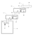
- FIG. 1 is a perspective view showing a configuration example of a hoop in which a robot and a substrate according to an embodiment of the present invention are housed.
- FIG. 2 is a plan view showing a configuration example of a hoop in which the robot and the substrate according to the embodiment of the present invention are housed.
- the robot 100 is a robot that transports substrates such as semiconductor wafers and glass wafers, for example.
- the robot 100 takes out a substrate from a FOUP (FOUP (Front Opening) Unified Pod) 150 and stores the substrate in the FOUP 150.
- FOUP Front Opening
- Examples of semiconductor wafers include silicon wafers, sapphire (single crystal alumina) wafers, and other various wafers.
- examples of the glass wafer include a glass substrate for FPD (Flat Panel Display) and a glass substrate for MEMS (Micro Electro Mechanical Systems).
- the hoop 150 includes a pair of side walls 151 that face each other, an upper wall 152 and a lower wall 153 that connect the upper and lower ends of the side wall 151, and a plurality of pairs of substrates provided on the side walls 151.
- a support portion 154 and first and second teaching targets 155a and 155b are provided.
- the front surface of the hoop 150 is open and constitutes a front opening 156. The robot 100 unloads the substrate from the hoop 150 through the front opening 156 and loads the substrate into the hoop 150.
- the substrate support unit 154 supports the end portions of the plurality of substrates W so that the plurality of substrates are arranged in a horizontal posture with an interval in the vertical direction. As shown in FIG. 2, for example, the center of the substrate supported by the substrate support portion 154 when viewed from the vertical direction constitutes the teaching point T, but is not limited thereto.
- the teaching point T means that the control unit 61 (to be described later) of the robot 100 detects the position of the teaching point T, so that the robot 100 can carry out the substrate P from the FOUP 150 or carry the substrate P into the FOUP 150. It is the position to make.
- the extending direction of the rotation axis L1 described later of the robot 100 is referred to as the z direction
- the direction orthogonal to the z direction is referred to as the x direction
- the direction orthogonal to the z direction and the x direction is referred to as the y direction.
- the x direction is set in the direction from the robot 100 toward the hoop 150 and in the opposite direction.
- the first and second teaching targets 155a and 155b are each formed in a columnar shape, for example, and are formed so as to protrude upward from the lower wall 153.
- the first and second teaching targets 155a and 155b are arranged in a line in a direction from one side wall 151 toward the other side wall 151. Further, the positional relationship between the first and second teaching targets 155a and 155b and the teaching point T in the xy plane is stored in advance in the storage unit 62 described later.
- the teaching point T is separated by a distance d in a direction in which a line orthogonal to the line extends from a midpoint of a line connecting the first and second teaching targets 155a and 155b, for example.
- the storage unit 62 stores the distance d, for example.
- FIG. 3 is a diagram illustrating a configuration example of the internal mechanism of the robot 100.
- the robot 100 includes a base 10, a lower arm 20, an upper arm 30, a hand 40, and a controller 60 (see FIG. 4) that controls the operation of the robot 100.
- the lower arm 20 and the upper arm 30 constitute an arm of the robot 100
- the lower arm 20, the upper arm 30 and the hand 40 constitute a robot arm of the robot 100.
- the base 10 is, for example, a hollow cylindrical member.
- a lower arm drive unit 15 including a servo motor is disposed inside the base 10.
- the lower arm drive unit 15 includes a lower arm rotating main gear 16.
- the robot 100 includes an elevating mechanism 18 (see FIG. 4).
- the elevating mechanism includes, for example, a well-known ball screw mechanism (not shown) and a servo motor with an encoder (elevating mechanism driving unit 19) for driving the elevating mechanism.
- a movable body (not shown) on which the arm driving unit 15 is installed in the z direction
- the lower arm 20, the upper arm 30, and the hand 40 are integrally moved in the z direction.
- the hand 40 can be moved up and down between the raised position and the lowered position.
- the height position of the lowered position is set lower than the height position of the lower wall 153 of the hoop 150. Further, the height position of the raised position is set higher than the height position of the uppermost substrate support portion 154.
- the lower arm 20 is, for example, a hollow plate-like member, and is formed in a substantially strip shape in plan view. As shown in FIG. 3, the lower arm 20 has a lower arm rotation shaft 21 formed so as to protrude downward from the bottom surface of the base end portion thereof.
- the lower arm rotation shaft 21 is attached to the base 10 so as to be rotatable about a rotation axis L1 extending in the z direction. Therefore, the lower arm 20 is configured to rotate in the xy plane.
- the rotation axis L1 constitutes the reference point O on the xy plane.
- a lower arm rotation driven gear 22 is fixed to the lower end of the lower arm rotation shaft 21.
- the lower arm rotating driven gear 22 is provided at the same height as the lower arm rotating main gear 16 of the base 10 and meshes with the lower arm rotating main gear 16.
- the lower arm 20 is provided with an upper arm drive unit 25 including a servo motor.
- the upper arm drive unit 25 includes an upper arm rotating main gear 26.
- the relative angular position around the rotation axis L1 with respect to the base 10 of the lower arm 20 is detected by the encoder of the servo motor of the lower arm drive unit 15.
- the upper arm 30 is, for example, a hollow plate-like member, and is formed in a substantially strip shape in plan view. As shown in FIG. 3, the upper arm 30 is provided with an upper arm rotation shaft 31 so as to protrude downward from the bottom surface of the base end portion 30a.
- the upper arm rotation shaft 31 is attached to the lower arm 20 so as to be rotatable about a rotation axis L2 extending in parallel with the rotation axis L1. Accordingly, the upper arm 30 is configured to rotate on the xy plane.
- the upper arm rotation driven gear 32 is fixed to the lower end portion of the upper arm rotation shaft 31.
- the upper arm rotation driven gear 32 is provided at the same height as the upper arm rotation main gear 26 of the lower arm 20 and meshes with the upper arm rotation main gear 26.
- the upper arm 30 has a hand drive unit 35 including a servo motor disposed therein.
- the hand drive unit 35 includes a hand rotation main gear 36.
- the relative angular position around the rotation axis L2 with respect to the lower arm 20 of the upper arm 30 is detected by the encoder of the servo motor of the upper arm drive unit 25.
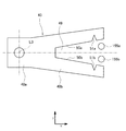
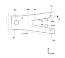
- the hand 40 includes a wrist 40 a formed on the proximal end side of the hand 40 and a blade 40 b formed on the distal end side of the hand 40.
- the list 40a and the blade 40b are formed continuously.
- the wrist 40a has a hand rotation shaft 41 formed so as to protrude downward from the bottom surface of the base end portion 40a.
- the hand rotation shaft 41 is attached to the hand 40 so as to be rotatable about a rotation axis L3 extending in parallel with the rotation axes L1 and L2. Therefore, the hand 40 is configured to rotate in the xy plane.
- a hand rotating driven gear 42 is fixed to the lower end portion of the hand rotating shaft 41.
- the hand rotation driven gear 42 is provided at the same height as the hand rotation main gear 36 and meshes with the hand rotation main gear 36.
- the relative angular position around the rotation axis L3 with respect to the upper arm 30 of the hand 40 is detected by the encoder of the servo motor of the hand drive unit 35.
- This encoder constitutes the hand angle position detector 37, but is not limited to this.
- the arm drive unit drives the lower arm 20 and the upper arm 30 to move the hand 40 in the xy plane.
- the blade 40b is formed in a thin plate shape, for example.
- the blade 40b holds the substrate P on the upper surface.
- the blade 40b has a contact sliding surface for sliding in contact with the teaching target.
- the abutting sliding surfaces are a pair of opposing surfaces, and the opposing abutting sliding surfaces oppose each other on the inner peripheral surface of the cutout portion 49 of the thin blade 40b. It is formed as a part to do.
- the pair of abutting sliding surfaces that face each other extend so that the distance between both ends becomes narrower from the distal end portion to the proximal end portion of the blade 40b.
- each abutting sliding surface gradually approaches the center line Lc extending from the proximal end of the blade 40b toward the distal end through the rotation axis L3 as it goes from the distal end portion to the proximal end portion of the blade 40b. And extends in a direction intersecting with the rotation direction of the hand 40 (in this example, a direction orthogonal thereto).
- the first teaching is more than the second teaching target 155b of the hoop 150 in a state where the hand 40 is positioned such that the direction from the proximal end to the distal end of the blade 40b is the x direction of the pair of facing surfaces.
- the contact sliding surface located on the target 155a side constitutes the first contact sliding surface 50a
- the contact sliding surface located on the second teaching target 155b side from the first teaching target 155a is the second contact contacting surface.
- a sliding surface 50b is configured.
- the first contact sliding surface 50a and the second contact sliding surface 50b are continuous surfaces that extend in a straight line as a whole.
- the first contact sliding surface 50a has a bending point in the direction in which the surface extends (first direction).
- the second contact sliding surface 50b has a bending point in the direction in which the surface extends.
- the bending point of the first contact sliding surface 50a is a notch formed by carving the first contact sliding surface 50a, and the first contact sliding surface 50a extends in a straight line. It is comprised so that it may become a recessed part recessed from the sliding surface 50a. Therefore, the notch forms a step in the direction (first direction) in which the first contact sliding surface 50a extends.
- step difference comprises the 1st characteristic part 51a. Therefore, the level
- the bending point of the second abutting sliding surface 50b is a notch formed by carving the second abutting sliding surface 50b, and the second abutting sliding surface 50b extends in a straight line. It is comprised so that it may become a recessed part recessed from the contact sliding surface 50b. Therefore, the notch forms a step in the direction in which the second contact sliding surface 50b extends.
- step difference comprises the 2nd characteristic part 51b. Therefore, the level
- the first feature portion 51a and the second feature portion 51b are formed symmetrically with respect to the center line Lc in the xy plane.
- FIG. 4 is a block diagram schematically showing a configuration example of the control system of the robot 100.
- the controller 60 provided in the robot 100 includes, for example, a control unit 61 having a computing unit such as a CPU and a storage unit 62 having a memory such as a ROM and a RAM.
- the controller 60 may be composed of a single controller that performs centralized control, or may be composed of a plurality of controllers that perform distributed control in cooperation with each other.
- the control unit 61 includes a lower arm control unit 64, an upper arm control unit 65, a hand control unit 66, a lifting mechanism control unit 67, a history recording unit 68, a teaching point position determination unit 69, and a target position determination unit 70.
- These functional units 64 to 70 are functional blocks realized when the control unit 61 executes a predetermined control program stored in the storage unit 62.
- the lower arm control unit 64 controls the lower arm driving unit 15 to rotate the lower arm 20 in the xy plane.
- the upper arm control unit 65 controls the upper arm drive unit 25 to rotate the upper arm 30 in the xy plane.
- the hand control unit 66 controls the hand drive unit 35 to rotate the hand 40 in the xy plane.
- the elevating mechanism control unit 67 controls the elevating mechanism driving unit 19 to integrally raise and lower the lower arm 20, the upper arm 30, and the hand 40 in the z direction.
- the main control unit (not shown) of the control unit 61 sets the target transport position of the robot 100 and the angular positions detected by the encoders of the drive units 15, 25, 35, and 19 respectively. Based on this, the target angular positions are output to the control units 64 to 67, respectively.
- the control units 64 to 67 respectively detect the angular position detected by the corresponding encoder so that the angular position of the corresponding control object (the lower arm 20, the upper arm 30, the hand 40, and the movable body) becomes the target angular position.
- the corresponding drive units 15, 25, 35, and 19 are feedback-controlled.
- the history recording unit 68 records information including control information of the lower arm 20, the upper arm 30 and the hand 40 by the control unit 61 and information related to the angular position of the hand 40 received from the hand angular position detection unit 37.
- this information includes information necessary for specifying the relationship between the position of the rotation axis L3 and the angular position of the hand 40.
- the target position determination unit 70 determines the positions of the first teaching target 155a and the second teaching target 155b based on information recorded in the history recording unit 68, as will be described in detail later.
- the teaching point position determination unit 69 determines the position of the teaching point T based on the target position determined by the target position determination unit 70, as will be described in detail later.
- a predetermined control program is stored in the storage unit 62, and the operation of the robot 100 is controlled by the control unit 61 reading and executing these control programs.
- the storage unit 62 stores the distance d in the x direction from the first and second teaching targets 155a and 155b to the teaching point T as described above.
- the storage unit 62 stores information for specifying the positions of the first feature unit 51a and the second feature unit 51b.
- 5 and 6 are flowcharts showing an operation example of the robot 100 according to the embodiment of the present invention.
- 7A to 7E are diagrams showing an operation example of the robot 100 according to the embodiment of the present invention.
- the control unit 61 positions the hand 40 at the initial position (step S10).
- This initial position is stored in the storage unit 62.
- the initial position is a set position where the first teaching target 155a and the second teaching target 155b are located in the gap 49 at the tip of the blade 40b.
- the initial position is stored in the storage unit 62, but is not limited thereto. For example, instead of this, a position where the first teaching target 155a and the second teaching target 155b are located in the gap 49 at the tip of the blade 40b is detected by a sensor, and the detected position is set as an initial position. Also good.
- the control unit 61 drives the hand driving unit 35 to rotate the hand 40 about the rotation axis L3, thereby causing the first teaching target 155a and the first contact sliding surface 50a to rotate.
- this rotation direction may be referred to as a first rotation direction t1
- a direction opposite to the first rotation direction t1 may be referred to as a second rotation direction t2.
- the control unit 61 controls the hand drive unit 35 so that the hand 40 can follow the shape change of the first contact sliding surface 50a.
- the control unit 61 can follow the change in the shape of the first contact sliding surface 50a by setting the angular position control loop gain of the hand drive unit 35 to substantially zero.
- the hand drive unit 35 is controlled (step S20). Setting the control loop gain to substantially zero means that the force that rotates the hand 40 in the direction of pressing the contact sliding surface that is in contact with the teaching target in the direction of the teaching target is in effect.
- the control loop gain is set so as to rotate in the opposite direction.
- the control unit 61 drives the lower arm driving unit 15 and the upper arm driving unit 25 to move the hand 40 in the direction in which the center line Lc extends (step S25).
- the first abutting sliding surface 50a extends asymptotically to the center line LC from the distal end portion to the proximal end portion of the blade 40b, and thus the direction in which the center line Lc extends through the hand 40.
- the first contact sliding surface 50a of the blade 40b is pressed against the first teaching target 155a.
- the hand 40 receives the reaction force received from the first teaching target 155a, rotates in the second rotation direction t2 around the rotation axis L3, and its angular position is displaced.
- the displacement of the angular position of the hand 40 is detected by the hand angular position detector 37. Then, the first teaching target 155a and the first contact sliding surface 50a move relatively so that the first teaching target 155a slides on the first contact sliding surface 50a. That is, when the control unit 61 moves the hand 40 in the direction in which the center line Lc extends, the first teaching target 155a relatively moves in the direction in which the first contact sliding surface 50a extends.
- the history recording unit 68 starts recording the history of the displacement of the relative angular position around the rotation axis L3 with respect to the upper arm 30 of the hand 40 detected by the hand angular position detection unit 37 (step S30).
- This history constitutes the first history H1.
- the history recording unit 68 records the history until the hand 40 moves a predetermined distance (step S35).
- the predetermined distance means that the first feature 51a and the second feature 51b of the blade 40b moved in the direction in which the center line Lc extends from the initial position are the first teaching target 155a and the second teaching. The distance from the target 155b to the position on the tip side of the blade 40b.
- the hand 40 is moved to the first contact sliding surface. Since the first teaching target 155a is configured to follow the shape change of the first characteristic portion 51a of the surface 50a, the first teaching target 155a extends from the first contact sliding surface 50a extending in a straight line to the notch of the first characteristic portion 51a. As a result, the hand 40 is greatly rotated in the first rotation direction t1, and its angular position is greatly displaced.
- the hand detected by the hand angular position detection unit 37 While the rate of change of the angular position of 40 takes a substantially constant value, when the first teaching target 155a enters the first feature portion 51a, the rate of change of the angular position of the hand 40 is the first extending linearly.
- symbol of the change rate in the area which is moving the hand 40 so that the 1st teaching target 155a moves relatively on the contact sliding surface 50a is shown (refer FIG. 8).
- the hand 40 When the hand 40 further moves, as described above, the hand 40 receives the reaction force received from the first teaching target 155a, so that the hand 40 has the shape of the first characteristic portion 51a of the first contact sliding surface 50a. Since the first teaching target 155a is configured to follow the change, the first teaching target 155a returns to the first abutting sliding surface 50a extending out from the notch of the first feature 51a and extending in a straight line. The hand 40 is greatly rotated in the second rotation direction t2, and its angular position is greatly displaced. That is, the change rate of the angular position of the hand 40 shows a large value opposite in sign to the change rate when the first teaching target 155a enters the first feature 51a (see FIG. 8).
- the hand 40 is largely rotated in the first rotation direction t1 in the first characteristic portion 51a, and is further rotated in the second rotation direction t2, and the change rate of the angular position is locally increased. Take a large value.
- the first characteristic portion 51a is configured by a step, the rate of change of the angular position of the hand 40 can be increased.
- control unit 61 acquires the first history H1 by executing Steps S10 to S35.
- control unit 61 positions the hand 40 again at the initial position (step S40).
- the control unit 61 drives the hand drive unit 35 to rotate the hand 40 about the rotation axis L3 to bring the second teaching target 155b into contact with the second contact sliding surface 50b (step S45). ). Since the first contact sliding surface 50a and the second contact sliding surface 50b are formed to face each other, the control unit 61 switches the rotation direction of the hand 40 located at the initial position. Any one of the first contact sliding surface 50a and the second contact sliding surface 50b can be selected as the contact sliding surface that contacts the teaching target. Therefore, teaching to the robot 100 can be performed quickly.
- step S35 since the distance for moving the hand 40 to bring the second teaching target 155b and the second contact sliding surface 50b into contact with each other after the execution of step S35 is shortened, for example, based on the backlash of the arm of the robot 100 A decrease in detection accuracy can be reduced, and detection accuracy can be improved.
- control unit 61 controls the hand drive unit 35 so that the hand 40 can follow the shape change of the first contact sliding surface 50a.
- the control unit 61 sets the control loop gain of the hand drive unit 35 to substantially zero so that the hand 40 can follow the shape change of the first contact sliding surface 50a.
- the hand drive unit 35 is controlled (step S50).
- the control unit 61 drives the lower arm driving unit 15 and the upper arm driving unit 25 to move the hand 40 in the direction in which the center line Lc extends (step S55).
- the second abutting sliding surface 50b extends asymptotically to the center line LC from the distal end portion of the hand 40 toward the base end portion, the direction in which the center line Lc extends from the hand 40 is increased.
- the second contact sliding surface 50b of the blade 40b is pressed against the second teaching target 155b.
- the hand 40 receives the reaction force received from the second teaching target 155b, rotates in the first rotation direction t1 around the rotation axis L3, and its angular position is displaced.
- the displacement of the angular position of the hand 40 is detected by the hand angular position detector 37. And the 2nd teaching target 155b and the 2nd contact sliding surface 50b move relatively so that the 2nd teaching target 155b slides on the 2nd contact sliding surface 50b. That is, when the control unit 61 moves the hand 40 in the direction in which the center line Lc extends, the second teaching target 155b relatively moves in the direction in which the second contact sliding surface 50b extends.
- the moving direction in which the hand 40 is moved in step S25 and step S55 is not limited to the direction in which the center line Lc extends, and the teaching target and the contact sliding surface relatively move in the direction in which the contact sliding surface extends.
- the hand 40 may be moved in an arbitrary direction.
- the history recording unit 68 starts recording the history of the displacement of the relative angular position around the rotation axis L3 with respect to the upper arm 30 of the hand 40 detected by the hand angular position detection unit 37 (step S60).
- This history constitutes the second history H2.
- the history recording unit 68 records the history until the hand 40 moves a predetermined distance (step S65).
- the hand 40 has the second feature of the second contact sliding surface 50b.
- the first teaching target 155a enters the notch of the second feature 51b from the second abutting sliding surface 50b extending in a straight line, and as a result, the hand 40 is configured to follow the shape change of 51b.
- Largely rotates in the second rotation direction t2, and its angular position is greatly displaced. That is, in the section in which the hand 40 is moved so that the second teaching target 155b moves relatively on the second abutting sliding surface 50b extending in a straight line, the hand detected by the hand angular position detection unit 37.
- the change rate of the angular position of 40 takes a substantially constant value.
- the change rate of the angular position of the hand 40 extends in a straight line. A large value of the same sign as the sign of the rate of change in the section in which the hand 40 is moved so that the second teaching target 155b relatively moves on the contact sliding surface 50b is shown (see FIG. 8).
- the hand 40 When the hand 40 further moves, as described above, the hand 40 receives the reaction force received from the second teaching target 155b, so that the hand 40 has the shape of the second characteristic portion 51b of the second contact sliding surface 50b. Since the second teaching target 155b is configured to follow the change, the second teaching target 155b returns to the second abutting sliding surface 50b extending straight from the notch of the second feature 51b, and as a result, The hand 40 is greatly rotated in the first rotation direction t1, and its angular position is greatly displaced. That is, the rate of change of the hand 40 shows a large value opposite to the rate of change when the second teaching target 155b enters the second feature 51b (see FIG. 8).
- the hand 40 is largely rotated in the second rotation direction t2 in the second feature 51b, and is further rotated in the first rotation direction t1, and the rate of change in the angular position is locally increased. Take a large value.
- the rate of change of the angular position of the hand 40 is a large value.
- control unit 61 acquires the second history H2 by executing Steps S40 to S65.
- the target position determination unit 70 determines the positions of the first teaching target 155a and the second teaching target 155b based on the first history H1 and the second history H2.
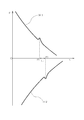
- FIG. 8 is a graph showing an example of the relationship between the position of the hand in the x direction and the relative angular position with respect to the upper arm of the hand, and is based on information included in the first history H1 and the second history H2. .
- the vertical axis ⁇ represents the relative angular position ⁇ of the hand 40 with respect to the x direction
- the horizontal axis x represents the position of the hand 40 in the x direction.
- the target position determination unit 70 first determines the positions P1 and P2 of the hand in which the value of ⁇ in the x direction has greatly changed for each of the first history H1 and the second history H2. In the present embodiment, the target position determination unit 70 determines the positions of the hand 40 in which the sign of the change rate of ⁇ is inverted in a section where the change rate of ⁇ exceeds a predetermined threshold as P1 and P2.
- the target position determination unit 70 determines P1 and P2 based on the fact that the sign of the change rate of ⁇ is inverted in addition to the section in which the change rate of ⁇ exceeds the predetermined threshold. Therefore, the positions of the first feature 51a and the second feature 51b can be detected with high accuracy.
- the rate of change of the angular position of the hand 40 becomes a large value, and P1 and P2 The position can be determined with high accuracy.
- the target position determination unit 70 determines the first feature 51a and the first feature in P1 and P2.
- the positions of the first teaching target 155a and the second teaching target 155b are determined based on the positions of the two feature portions 51b.
- the positions P1x and P2x in the x direction and the positions P1y and P2y in the y direction of the first teaching target 155a and the second teaching target 155b are determined based on the following equations.
- the teaching point position determination unit 69 includes the first teaching target 155a and the second teaching target 155b.
- the position Tx in the x direction and the position Ty in the y direction of the teaching point T are determined based on the positions of As described above, in the present embodiment, the position of the teaching point T is a point separated by a distance d from the midpoint of the line connecting the first teaching target 155a and the second teaching target 155b in the direction in which the line orthogonal to this line extends. And is determined based on the following equation.
- the control unit 61 detects the positions of the first teaching target 155a and the second teaching target 155b and determines the position of the teaching point T, so that the hoop 150 viewed from the vertical direction is used. Regardless of the position, the position of the teaching point T can be determined with high accuracy.
- the teaching target is based on the change in the angular position of the hand 40 in the xy plane due to the characteristic part. It is possible to detect the position of the hand 40 when is positioned at the feature, and based on this, the position of the teaching target in the x and y directions can be detected. Therefore, the position of the teaching target can be quickly detected, and further, the position of the teaching point T can be quickly taught based on the detected position of the teaching target.
- the first feature 51a and the second feature 51b of the blade 40b are recesses that are recessed from the first abutting sliding surface 50a.
- the change rate of the angular position takes a large value locally in the feature portion, the position of the teaching target can be detected with high accuracy.
- the conventional hand blade is additionally processed to form the first contact sliding surface 50a and the second contact sliding surface 50b including the first feature 51a and the second feature 51b. Since the robot can be taught, it is advantageous for manufacturing and the manufacturing cost is low.
- step S15 and step S45 the hand 40 is rotated to bring the hand 40 and the teaching target into contact with each other.
- the present invention is not limited to this.
- the hand 40 may be moved in the y direction so that the hand 40 and the teaching target are brought into contact with each other.
- the 1st characteristic part 51a and the 2nd characteristic part 51b were made into the notch formed by carving the 1st contact sliding surface 50a and the 2nd contact sliding surface 50b, to this It is not limited. Instead, these characteristic portions may be convex portions protruding from the first contact sliding surface 50a and the second contact sliding surface 50b.
- the angular position control loop gain of the hand drive unit 35 may be set to zero.
- the contact sliding surface is formed to extend in a straight line, but is not limited to this.
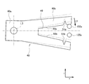
- the first contact sliding surface 250a and the second contact sliding surface 250b are formed so as to extend stepwise when viewed from the normal direction of the xy plane.
- the first feature portions 251aa and 251ab and the second feature portions 251ba and 251bb may be formed on the first contact slide surface 250a and the second contact slide surface 250b.
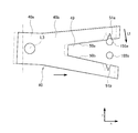
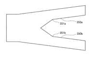
- the first contact sliding surface 350a and the second contact sliding surface 350b are formed so as to bend and extend when viewed from the normal direction of the xy plane, and the first contact sliding surface 350a and the first contact sliding surface 350a are formed.
- the first feature portion 351a and the second feature portion 351b may be formed on the two abutting sliding surface 350b.
- the present invention can be applied to a robot that transports a substrate in equipment for processing the substrate.
Landscapes
- Engineering & Computer Science (AREA)
- Mechanical Engineering (AREA)
- Robotics (AREA)
- Manipulator (AREA)
- Container, Conveyance, Adherence, Positioning, Of Wafer (AREA)
Abstract
Description
(実施の形態)
図1は、本発明の実施の形態に係るロボット及び基板が収納されているフープの構成例を示す斜視図である。図2は、本発明の実施の形態に係るロボット及び基板が収納されているフープの構成例を示す平面図である。
[ロボットの構成]
図3は、ロボット100の内部機構の構成例を示す図である。
[制御部]
図4は、ロボット100の制御系統の構成例を概略的に示すブロック図である。
そして、記憶部62には、上述した通り、第1及び第2の教示ターゲット155a,155bから教示点Tまでのx方向における距離dが記憶されている。また、記憶部62には、第1特徴部51a及び第2特徴部51bの位置を特定するための情報が記憶されている。
[動作例]
次に、ロボット100に教示点Tの位置を教示する際のロボット100の動作例を説明する。
La:y方向における第1特徴部51aと第2特徴部51bとの距離
Lb:x方向におけるP1とP2の距離
次に、ターゲット位置決定部70は、P1及びP2における第1特徴部51a及び第2特徴部51bの位置に基づいて、それぞれ第1教示ターゲット155a及び第2教示ターゲット155bの位置を決定する。本実施の形態において、第1教示ターゲット155a及び第2教示ターゲット155bのx方向における位置P1x及びP2x、並びにy方向における位置P1y及びP2yは次式に基づいて決定される。
P1y=L3y+R・sin(θc+α)
P2x=L3x+R・cos(θc-α)
P2y=L3y+R・sin(θc-α)
θc:xy平面において、ハンド40の中心線Lcとx軸が成す角度
R:xy平面において、回動軸線L3とブレード40bの第1特徴部51a及び第2特徴部51bとの距離(図2参照)
(なお、上述の通り、第1特徴部51a及び第2特徴部51bは、中心線Lcを介して線対称に形成されているので、第1特徴部51aに係る距離Rと第2特徴部51bに係る距離Rは同一である。)
α:xy平面において、中心線Lcに対して、第1特徴部51aと回動軸線L3とを結ぶ線が成す角度(図2参照)
(なお、上述の通り、第1特徴部51a及び第2特徴部51bは、中心線Lcを介して線対称に形成されているので、xy平面において、中心線Lcに対して、第2特徴部51bと回動軸線L3とを結ぶ線が成す角度は-αである。)
L3x:xy平面における回動軸線L3のx方向の位置
L3y:xy平面における回動軸線L3のy方向の位置
次に、教示点位置決定部69は、第1教示ターゲット155a及び第2教示ターゲット155bの位置に基づいて、教示点Tのx方向における位置Tx及びy方向における位置Tyを決定する。上述の通り、本実施の形態において、教示点Tの位置は、第1教示ターゲット155a及び第2教示ターゲット155bを結ぶ線の中点からこの線と直交する線が延びる方向に距離d離れた点であり、次式に基づいて決定される。
Tx=((Py1+Py2)/2)+d・(|Px2-Px1|/L)
L=√((Px2-Px1)^2+(Py2-Py1)^2)
このように、本実施の形態において、制御部61は、第1教示ターゲット155a及び第2教示ターゲット155bの位置を検出した上で教示点Tの位置を決定するため、鉛直方向から見たフープ150の位置に関わらず、教示点Tの位置を精度よく決定することができる。
上記実施の形態においては、ステップS15及びステップS45において、ハンド40を回動させて、ハンド40と教示ターゲットとを接触させたがこれに限られるものではない。これに代えて、ハンド40をy方向に移動させてハンド40と教示ターゲットとを接触させてもよい。
15 下アーム駆動部
16 下アーム回動用主働ギヤ
18 昇降機構
19 昇降機構駆動部
20 下アーム
21 下アーム回動軸
22 下アーム回動用従動ギヤ
25 上アーム駆動部
26 上アーム回動用主働ギヤ
30 上アーム
31 上アーム回動軸
32 上アーム回動用従動ギヤ
35 ハンド駆動部
36 ハンド回動用主働ギヤ
37 ハンド角度位置検出部
40 ハンド
40a リスト
40b ブレード
41 ハンド回動軸
42 ハンド回動用従動ギヤ
49 間隙
50a 第1当接摺動面
50b 第2当接摺動面
51a 第1特徴部
51b 第2特徴部
61 制御部
62 記憶部
64 下アーム制御部
65 上アーム制御部
66 ハンド制御部
67 昇降機構制御部
68 履歴記録部
69 教示点位置決定部
70 ターゲット位置決定部
100 ロボット
150 フープ
151 側壁
152 上壁
153 下壁
154 基板支持部
155a 第1教示ターゲット
155b 第2教示ターゲット
156 前面開口
Claims (6)
- アームと、該アームの先端部に回動軸線を中心に回動自在に取り付けられたハンドと、を含むロボットアームと、
前記アームを駆動して前記ハンドを移動させるアーム駆動部と、
前記ハンドを回動させるハンド駆動部と、
前記ハンドの前記回動軸線周りの角度位置を検出するハンド角度位置検出部と、
前記アーム駆動部と前記ハンド駆動部とを制御する制御部と、を備え、
前記ハンドは、全体が第1方向に延びる、教示ターゲットと当接して摺動するための当接摺動面を有するブレードを含み、
前記当接摺動面は、前記第1方向において屈曲点を有する特徴部を含む、ロボット。 - 前記特徴部は前記第1方向における段差である、請求項1に記載のロボット。
- 前記制御部は、少なくとも前記アーム駆動部を制御することによって前記教示ターゲットが前記当接摺動面上を前記第1方向又は前記第1方向と反対方向に相対的に移動するように前記ハンドを移動させ、且つ前記ハンド角度位置検出部によって検出される、前記特徴部に起因する第1方向と交差する方向の前記ハンドの角度位置の変位に基づいて、前記教示ターゲットの位置を検出するよう構成されている、請求項1又は2に記載のロボット。
- 前記制御部は、前記ハンド駆動部を制御することによって前記ハンドが前記当接摺動面の特徴部の形状変化に追従しうるよう構成されている、請求項3に記載のロボット。
- 前記特徴部は、前記当接摺動面から突出する凸部又は前記当接摺動面から凹陥する凹部である、請求項1乃至4のいずれかに記載のロボット。
- アームと、該アームの先端部に回動軸線を中心に回動自在に取り付けられたハンドと、を含むロボットアームと、前記アームを駆動して前記ハンドを移動させるアーム駆動部と、前記ハンドを回動させるハンド駆動部と、前記ハンドの前記回動軸線周りの角度位置を検出するハンド角度位置検出部と、前記アーム駆動部と前記ハンド駆動部とを制御する制御部と、を備えるロボットの制御方法であって、
前記ハンドは、全体が第1方向に延びる、教示ターゲットと当接して摺動するための当接摺動面を有するブレードを含み、
前記当接摺動面は、前記第1方向において屈曲点を有する特徴部を含み、
前記制御部が少なくとも前記アーム駆動部を制御することによって前記教示ターゲットが前記当接摺動面上を前記第1方向又は前記第1方向と反対方向に相対的に移動するように前記ハンドを前記第2方向に移動させ、且つ前記ハンド角度位置検出部によって検出される、前記特徴部に起因する前記当接摺動面に交差する方向の前記ハンドの角度位置の変位に基づいて、前記教示ターゲットの位置を検出する、ロボットの制御方法。
Priority Applications (4)
| Application Number | Priority Date | Filing Date | Title |
|---|---|---|---|
| US15/026,926 US9972523B2 (en) | 2013-10-01 | 2014-09-30 | Robot and control method of robot |
| KR1020167010054A KR101810112B1 (ko) | 2013-10-01 | 2014-09-30 | 로봇 및 로봇의 제어 방법 |
| CN201480054199.4A CN105579203B (zh) | 2013-10-01 | 2014-09-30 | 机械手及机械手的控制方法 |
| EP14851191.8A EP3053712B1 (en) | 2013-10-01 | 2014-09-30 | Robot and control method of robot |
Applications Claiming Priority (2)
| Application Number | Priority Date | Filing Date | Title |
|---|---|---|---|
| JP2013-206634 | 2013-10-01 | ||
| JP2013206634A JP6438189B2 (ja) | 2013-10-01 | 2013-10-01 | ロボット及びロボットの制御方法 |
Publications (1)
| Publication Number | Publication Date |
|---|---|
| WO2015049858A1 true WO2015049858A1 (ja) | 2015-04-09 |
Family
ID=52778463
Family Applications (1)
| Application Number | Title | Priority Date | Filing Date |
|---|---|---|---|
| PCT/JP2014/004987 Ceased WO2015049858A1 (ja) | 2013-10-01 | 2014-09-30 | ロボット及びロボットの制御方法 |
Country Status (7)
| Country | Link |
|---|---|
| US (1) | US9972523B2 (ja) |
| EP (1) | EP3053712B1 (ja) |
| JP (1) | JP6438189B2 (ja) |
| KR (1) | KR101810112B1 (ja) |
| CN (1) | CN105579203B (ja) |
| TW (1) | TWI544996B (ja) |
| WO (1) | WO2015049858A1 (ja) |
Cited By (1)
| Publication number | Priority date | Publication date | Assignee | Title |
|---|---|---|---|---|
| CN112540536A (zh) * | 2020-11-27 | 2021-03-23 | 南京航空航天大学 | 一种蠕虫管道机器人滑模优化控制器设计方法 |
Families Citing this family (8)
| Publication number | Priority date | Publication date | Assignee | Title |
|---|---|---|---|---|
| US10029366B2 (en) * | 2014-11-21 | 2018-07-24 | Canon Kabushiki Kaisha | Control device for motor drive device, control device for multi-axial motor, and control method for motor drive device |
| WO2016103292A1 (ja) * | 2014-12-22 | 2016-06-30 | 川崎重工業株式会社 | ロボットシステム及びエンドエフェクタの変形検出方法 |
| CN106956290B (zh) | 2017-04-17 | 2019-09-10 | 京东方科技集团股份有限公司 | 机械臂及其操作方法、机械臂装置及显示面板生产设备 |
| JP7225613B2 (ja) * | 2018-09-03 | 2023-02-21 | 東京エレクトロン株式会社 | 基板搬送機構、基板処理装置及び基板搬送方法 |
| KR102193994B1 (ko) * | 2019-03-29 | 2020-12-23 | 주식회사 나인벨 | 반도체 웨이퍼 이온주입 스캔로봇 |
| US11004713B2 (en) * | 2019-05-16 | 2021-05-11 | Taiwan Semiconductor Manufacturing Co., Ltd. | Robot arm device and method for transferring wafer |
| US11370114B2 (en) * | 2019-12-09 | 2022-06-28 | Applied Materials, Inc. | Autoteach enclosure system |
| JP7550042B2 (ja) * | 2020-12-09 | 2024-09-12 | 川崎重工業株式会社 | ロボット及び教示方法 |
Citations (6)
| Publication number | Priority date | Publication date | Assignee | Title |
|---|---|---|---|---|
| JPH0871969A (ja) * | 1994-09-02 | 1996-03-19 | Fanuc Ltd | ロボットの位置教示方法 |
| US6242879B1 (en) * | 2000-03-13 | 2001-06-05 | Berkeley Process Control, Inc. | Touch calibration system for wafer transfer robot |
| JP2004500993A (ja) * | 2000-05-03 | 2004-01-15 | バークレー・プロセス・コントロール・インコーポレーテッド | 自己教示ロボット・ウェハ・ハンドリング・システム |
| JP2010004635A (ja) | 2008-06-19 | 2010-01-07 | Daikin Ind Ltd | 界磁子及びその製造方法並びに回転電機 |
| WO2010004635A1 (ja) * | 2008-07-10 | 2010-01-14 | 川崎重工業株式会社 | ロボット及びその教示方法 |
| JP2013056420A (ja) | 2012-12-25 | 2013-03-28 | Kawasaki Heavy Ind Ltd | ロボットのターゲット位置検出装置 |
Family Cites Families (21)
| Publication number | Priority date | Publication date | Assignee | Title |
|---|---|---|---|---|
| US6366830B2 (en) * | 1995-07-10 | 2002-04-02 | Newport Corporation | Self-teaching robot arm position method to compensate for support structure component alignment offset |
| US5783834A (en) * | 1997-02-20 | 1998-07-21 | Modular Process Technology | Method and process for automatic training of precise spatial locations to a robot |
| US6056504A (en) * | 1998-06-05 | 2000-05-02 | Applied Materials, Inc. | Adjustable frog-leg robot |
| JP4601130B2 (ja) * | 2000-06-29 | 2010-12-22 | 日本エー・エス・エム株式会社 | ウエハーハンドリングロボットのティーチング装置および方法 |
| US6678581B2 (en) * | 2002-01-14 | 2004-01-13 | Taiwan Semiconductor Manufacturing Co. Ltd | Method of calibrating a wafer edge gripping end effector |
| TW558058U (en) * | 2002-05-03 | 2003-10-11 | Nanya Technology Corp | Wafer carrying apparatus |
| US20040013503A1 (en) * | 2002-07-22 | 2004-01-22 | Jaswant Sandhu | Robotic hand with multi-wafer end effector |
| JP4501103B2 (ja) * | 2003-10-17 | 2010-07-14 | 株式会社安川電機 | 半導体ウェハ搬送ロボットのキャリブレーション方法およびそれを備えた半導体ウェハ搬送ロボット、ウェハ搬送装置 |
| WO2005055312A1 (ja) | 2003-12-04 | 2005-06-16 | Hirata Corporation | 基板位置決めシステム |
| JP4047826B2 (ja) * | 2004-03-25 | 2008-02-13 | 東京エレクトロン株式会社 | 縦型熱処理装置及び移載機構の自動教示方法 |
| TWI398335B (zh) * | 2006-11-27 | 2013-06-11 | 日本電產三協股份有限公司 | Workpiece conveying system |
| JP5235376B2 (ja) | 2007-10-05 | 2013-07-10 | 川崎重工業株式会社 | ロボットのターゲット位置検出装置 |
| JP5114805B2 (ja) * | 2008-07-10 | 2013-01-09 | 川崎重工業株式会社 | ロボット及びその教示方法 |
| JP5402284B2 (ja) * | 2008-12-18 | 2014-01-29 | 株式会社安川電機 | 基板搬送ロボット、基板搬送装置、半導体製造装置および基板搬送ロボットの干渉物回避方法 |
| JP5504641B2 (ja) * | 2009-02-13 | 2014-05-28 | 株式会社安川電機 | 基板搬送用ロボット及びそれを備えた基板搬送装置、半導体製造装置 |
| KR101871212B1 (ko) * | 2010-11-26 | 2018-06-27 | 로제 가부시키가이샤 | 로봇의 제어 장치 및 제어 방법 |
| US8958907B2 (en) * | 2011-03-31 | 2015-02-17 | Sinfonia Technology Co., Ltd. | Robot arm apparatus |
| JP5810929B2 (ja) * | 2012-01-13 | 2015-11-11 | シンフォニアテクノロジー株式会社 | ウェーハ搬送装置 |
| JP5621796B2 (ja) * | 2012-01-31 | 2014-11-12 | 株式会社安川電機 | 搬送システム |
| JP5541299B2 (ja) * | 2012-01-31 | 2014-07-09 | 株式会社安川電機 | 搬送システム |
| JP6511806B2 (ja) * | 2014-12-25 | 2019-05-15 | シンフォニアテクノロジー株式会社 | 多関節ロボット及び多関節ロボットの制御方法 |
-
2013
- 2013-10-01 JP JP2013206634A patent/JP6438189B2/ja active Active
-
2014
- 2014-09-30 KR KR1020167010054A patent/KR101810112B1/ko active Active
- 2014-09-30 EP EP14851191.8A patent/EP3053712B1/en active Active
- 2014-09-30 WO PCT/JP2014/004987 patent/WO2015049858A1/ja not_active Ceased
- 2014-09-30 US US15/026,926 patent/US9972523B2/en active Active
- 2014-09-30 CN CN201480054199.4A patent/CN105579203B/zh active Active
- 2014-10-01 TW TW103134181A patent/TWI544996B/zh active
Patent Citations (6)
| Publication number | Priority date | Publication date | Assignee | Title |
|---|---|---|---|---|
| JPH0871969A (ja) * | 1994-09-02 | 1996-03-19 | Fanuc Ltd | ロボットの位置教示方法 |
| US6242879B1 (en) * | 2000-03-13 | 2001-06-05 | Berkeley Process Control, Inc. | Touch calibration system for wafer transfer robot |
| JP2004500993A (ja) * | 2000-05-03 | 2004-01-15 | バークレー・プロセス・コントロール・インコーポレーテッド | 自己教示ロボット・ウェハ・ハンドリング・システム |
| JP2010004635A (ja) | 2008-06-19 | 2010-01-07 | Daikin Ind Ltd | 界磁子及びその製造方法並びに回転電機 |
| WO2010004635A1 (ja) * | 2008-07-10 | 2010-01-14 | 川崎重工業株式会社 | ロボット及びその教示方法 |
| JP2013056420A (ja) | 2012-12-25 | 2013-03-28 | Kawasaki Heavy Ind Ltd | ロボットのターゲット位置検出装置 |
Non-Patent Citations (1)
| Title |
|---|
| See also references of EP3053712A4 |
Cited By (1)
| Publication number | Priority date | Publication date | Assignee | Title |
|---|---|---|---|---|
| CN112540536A (zh) * | 2020-11-27 | 2021-03-23 | 南京航空航天大学 | 一种蠕虫管道机器人滑模优化控制器设计方法 |
Also Published As
| Publication number | Publication date |
|---|---|
| JP6438189B2 (ja) | 2018-12-12 |
| US9972523B2 (en) | 2018-05-15 |
| TW201520013A (zh) | 2015-06-01 |
| KR20160060087A (ko) | 2016-05-27 |
| EP3053712A4 (en) | 2017-04-19 |
| EP3053712A1 (en) | 2016-08-10 |
| EP3053712B1 (en) | 2022-04-06 |
| US20160247707A1 (en) | 2016-08-25 |
| CN105579203A (zh) | 2016-05-11 |
| CN105579203B (zh) | 2018-09-07 |
| JP2015071191A (ja) | 2015-04-16 |
| KR101810112B1 (ko) | 2017-12-18 |
| TWI544996B (zh) | 2016-08-11 |
Similar Documents
| Publication | Publication Date | Title |
|---|---|---|
| JP6438189B2 (ja) | ロボット及びロボットの制御方法 | |
| JP5114805B2 (ja) | ロボット及びその教示方法 | |
| KR102105580B1 (ko) | 기판 반송 장치 및 기판 반송 로봇의 교시 방법 | |
| US8121732B2 (en) | Target position detection apparatus for robot | |
| US9796086B2 (en) | Method of teaching robot and robot | |
| US8688276B2 (en) | Teaching method for transfer robot | |
| JP4656334B2 (ja) | アライメント装置 | |
| JP5114804B2 (ja) | ロボット及びその教示方法 | |
| US9095984B2 (en) | Force control robot | |
| US11839968B2 (en) | Substrate transfer device and method of operating the same | |
| KR101209020B1 (ko) | 반송 로봇의 진단 시스템 | |
| KR102195817B1 (ko) | 기판 반송 장치 | |
| JP2012152898A (ja) | ロボットのターゲット位置検出装置、半導体装置およびターゲット位置検出方法 | |
| TWI796064B (zh) | 基板搬送機器人的控制裝置、機器人系統以及關節馬達的控制方法 | |
| JP6314429B2 (ja) | ロボット、ロボットシステム、及びロボット制御装置 | |
| JP5401748B2 (ja) | ロボット及びその教示方法 | |
| JP7149815B2 (ja) | ロボットシステム及びその運転方法 | |
| JP5620463B2 (ja) | ロボットのターゲット位置検出装置 | |
| JP4742663B2 (ja) | アライメント装置 |
Legal Events
| Date | Code | Title | Description |
|---|---|---|---|
| WWE | Wipo information: entry into national phase |
Ref document number: 201480054199.4 Country of ref document: CN |
|
| 121 | Ep: the epo has been informed by wipo that ep was designated in this application |
Ref document number: 14851191 Country of ref document: EP Kind code of ref document: A1 |
|
| NENP | Non-entry into the national phase |
Ref country code: DE |
|
| WWE | Wipo information: entry into national phase |
Ref document number: 15026926 Country of ref document: US |
|
| ENP | Entry into the national phase |
Ref document number: 20167010054 Country of ref document: KR Kind code of ref document: A |
|
| REEP | Request for entry into the european phase |
Ref document number: 2014851191 Country of ref document: EP |
|
| WWE | Wipo information: entry into national phase |
Ref document number: 2014851191 Country of ref document: EP |