WO2015052976A1 - 回転電機に配設される界磁極用磁石体を構成する磁石片を製造する製造方法及び製造装置 - Google Patents
回転電機に配設される界磁極用磁石体を構成する磁石片を製造する製造方法及び製造装置 Download PDFInfo
- Publication number
- WO2015052976A1 WO2015052976A1 PCT/JP2014/069970 JP2014069970W WO2015052976A1 WO 2015052976 A1 WO2015052976 A1 WO 2015052976A1 JP 2014069970 W JP2014069970 W JP 2014069970W WO 2015052976 A1 WO2015052976 A1 WO 2015052976A1
- Authority
- WO
- WIPO (PCT)
- Prior art keywords
- magnet
- magnet body
- cleaving
- coating film
- cleaved
- Prior art date
- Legal status (The legal status is an assumption and is not a legal conclusion. Google has not performed a legal analysis and makes no representation as to the accuracy of the status listed.)
- Ceased
Links
Images





Classifications
-
- B—PERFORMING OPERATIONS; TRANSPORTING
- B26—HAND CUTTING TOOLS; CUTTING; SEVERING
- B26F—PERFORATING; PUNCHING; CUTTING-OUT; STAMPING-OUT; SEVERING BY MEANS OTHER THAN CUTTING
- B26F3/00—Severing by means other than cutting; Apparatus therefor
- B26F3/002—Precutting and tensioning or breaking
-
- H—ELECTRICITY
- H01—ELECTRIC ELEMENTS
- H01F—MAGNETS; INDUCTANCES; TRANSFORMERS; SELECTION OF MATERIALS FOR THEIR MAGNETIC PROPERTIES
- H01F41/00—Apparatus or processes specially adapted for manufacturing or assembling magnets, inductances or transformers; Apparatus or processes specially adapted for manufacturing materials characterised by their magnetic properties
- H01F41/02—Apparatus or processes specially adapted for manufacturing or assembling magnets, inductances or transformers; Apparatus or processes specially adapted for manufacturing materials characterised by their magnetic properties for manufacturing cores, coils, or magnets
- H01F41/0253—Apparatus or processes specially adapted for manufacturing or assembling magnets, inductances or transformers; Apparatus or processes specially adapted for manufacturing materials characterised by their magnetic properties for manufacturing cores, coils, or magnets for manufacturing permanent magnets
-
- H—ELECTRICITY
- H01—ELECTRIC ELEMENTS
- H01F—MAGNETS; INDUCTANCES; TRANSFORMERS; SELECTION OF MATERIALS FOR THEIR MAGNETIC PROPERTIES
- H01F41/00—Apparatus or processes specially adapted for manufacturing or assembling magnets, inductances or transformers; Apparatus or processes specially adapted for manufacturing materials characterised by their magnetic properties
- H01F41/02—Apparatus or processes specially adapted for manufacturing or assembling magnets, inductances or transformers; Apparatus or processes specially adapted for manufacturing materials characterised by their magnetic properties for manufacturing cores, coils, or magnets
- H01F41/0253—Apparatus or processes specially adapted for manufacturing or assembling magnets, inductances or transformers; Apparatus or processes specially adapted for manufacturing materials characterised by their magnetic properties for manufacturing cores, coils, or magnets for manufacturing permanent magnets
- H01F41/026—Apparatus or processes specially adapted for manufacturing or assembling magnets, inductances or transformers; Apparatus or processes specially adapted for manufacturing materials characterised by their magnetic properties for manufacturing cores, coils, or magnets for manufacturing permanent magnets protecting methods against environmental influences, e.g. oxygen, by surface treatment
-
- H—ELECTRICITY
- H02—GENERATION; CONVERSION OR DISTRIBUTION OF ELECTRIC POWER
- H02K—DYNAMO-ELECTRIC MACHINES
- H02K15/00—Processes or apparatus specially adapted for manufacturing, assembling, maintaining or repairing of dynamo-electric machines
- H02K15/02—Processes or apparatus specially adapted for manufacturing, assembling, maintaining or repairing of dynamo-electric machines of stator or rotor bodies
- H02K15/03—Processes or apparatus specially adapted for manufacturing, assembling, maintaining or repairing of dynamo-electric machines of stator or rotor bodies having permanent magnets
Definitions
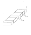
- a field pole magnet body disposed in a rotating electrical machine a plate-like magnet body (hereinafter simply referred to as “magnet body”) is cleaved into a plurality of magnet pieces, and the plurality of magnet pieces are bonded to each other.
- a field pole magnet body formed by doing so is known.
- Such a field pole magnet body is formed of a plurality of magnet pieces, so that the volume of each magnet piece can be reduced, and the eddy current generated in the magnet piece due to the fluctuation of the magnetic field due to the rotation of the rotor is reduced. be able to.
- production of an eddy current can be suppressed, and an irreversible thermal demagnetization can be prevented (refer patent document 1).
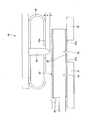
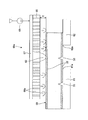
- FIG. 6C is a diagram illustrating a cleaving process of the manufacturing apparatus according to the first embodiment.
- FIG. 6D is a diagram illustrating a cleaving process of the manufacturing apparatus according to the first embodiment.
- FIG. 7 is a schematic configuration diagram illustrating another example of the manufacturing apparatus according to the first embodiment.
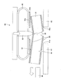
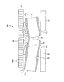
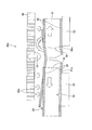
- FIG. 8A is a diagram illustrating a cleaving process of the manufacturing apparatus according to the second embodiment.
- FIG. 8B is a diagram illustrating a cleaving process of the manufacturing apparatus according to the second embodiment.
- FIG. 8C is a diagram illustrating a cleaving process of the manufacturing apparatus according to the second embodiment.
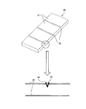
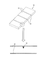
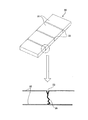
- a weakened portion made of a notch groove 33 or the like is formed in advance in a portion (scheduled cutting line) of the magnet body 30 as shown in FIG. 3A. It is effective to do.
- the notch groove 33 provided as the fragile portion is deeper from the surface, and the sharpness of the bottom of the notch groove 33 is sharper, the flatness of the cut section 36 when cleaved as the magnet piece 31 is improved. .
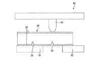
- the blade 43 is lowered by a magnet conveyance device (not shown) in a state in which the cutout groove 33 as a cutting line is positioned so as to be positioned between the pair of dies 41 and 42.
- the blade 43 presses the back side of the cutout groove 33 downward, and the magnet body 30 is cut by bending the blade 43 and the edge portions 41a, 42a of the pair of dies 41, 42 adjacent to each other. Cleaving along the notch 33 (FIG. 4B).
- the magnet body 30 and the magnet piece 31 can be completely separated including the coating film 35. Then, the blade 63 is raised (FIG. 6D). Next, in order to cleave the next magnet piece 31, the magnet body 30 is fed by one magnet piece 31 in the feeding direction by the magnet conveying device 64, and the magnet piece 31 and the coating film 35 are included by the same procedure. Divide and repeat the above steps as many times as necessary.
- the coating film cutting step is executed by pressing the end of the magnet piece 31 opposite to the split section 36 side with a magnet presser 65 formed of an elastic body. For this reason, when the cleaved magnet body 30 and the magnet piece 31 contact the magnet presser 65, it is possible to prevent the cleaved magnet body 30 and the magnet piece 31 from being lost.
- FIG. 8A to 8C show a second embodiment of a manufacturing method and a manufacturing apparatus for manufacturing a magnet piece constituting a field pole magnet body arranged in a rotating electrical machine to which the present invention is applied.
- FIG. 8A shows a magnet piece.
- FIG. 8B and FIG. 8C are explanatory views showing the operating state thereof.
- suppresses a magnet body and a magnet piece with the means to eject gas (air) is added to 1st Embodiment.
- the same devices as those in the first embodiment are denoted by the same reference numerals, and description thereof is omitted or simplified.
- the manufacturing apparatus 60a of the present embodiment includes a nozzle plate 66 that is integrally formed with the blade 63 and blows air from both sides of the blade 63 toward the magnet body 30 as the magnet presser 65. Also in this embodiment, the tip of the blade 63 is configured to be positioned below the lower surface of the nozzle plate 66 by a predetermined distance X as in the first embodiment.
- the magnet holder 65 of this embodiment includes a nozzle plate 66 and an air reservoir 67.
- the nozzle plate 66 has a large number of nozzle holes 66 a in the direction perpendicular to the surface of the magnet body 30, and is integrated with the blade 63.
- the air reservoir 67 is provided on the back surface of the nozzle plate 66 so that the supplied air is distributed and supplied to the nozzle holes 66a of the nozzle plate 66. Air is supplied to the air reservoir 67 from the air supply device 68, and the supplied air is dispersed in the nozzle holes 66 a of the nozzle plate 66 by the air reservoir 57 and directed toward the surface of the magnet body 30 through the nozzle holes 66 a. Is injected. Other configurations are the same as those in the first embodiment.
- the cleaved magnet body 30 and the magnet piece 31 are inclined (FIG. 8B). That is, the magnet body 30 immediately after the cleaving is rotated so as to incline obliquely with the edge 61a of the die 61 as a fulcrum and the end portion on the side of the split section 36 (front end side in the conveying direction) in the state of being in contact with the lowered blade 63. To do. Further, the magnet piece 31 cleaved at the tip of the magnet body 30 rotates and moves so as to incline obliquely with the edge 62a of the die 62 as a fulcrum and the split section 36 side end (the rear end side in the transport direction) downward. .
- the coating film 35 between the magnet body 30 and the magnet piece 31 on the tip side is cut off on the lower surface side and the side surface side of the magnet body 30 and the magnet piece 31 by the fractured surface 36 generated by the notch groove 33.
- the upper surface side of the magnet body 30 is not cut.
- the magnet body 30 and the magnet piece 31 are respectively pressed downward or rebounded by the air jet from the nozzle plate 66, and the posture is returned so as to be inclined along the support surfaces of the dies 61 and 62. Since the magnet retainer 65 is formed by the nozzle plate 66 that ejects air, the cleaved magnet body 30 and the magnet piece 31 can be prevented from coming into contact with the nozzle plate 66, and the cleaved magnet body 30 and It is possible to prevent the magnet piece 31 from being lost.
Landscapes
- Engineering & Computer Science (AREA)
- Power Engineering (AREA)
- Manufacturing & Machinery (AREA)
- Life Sciences & Earth Sciences (AREA)
- Forests & Forestry (AREA)
- Mechanical Engineering (AREA)
- Environmental & Geological Engineering (AREA)
- Permanent Field Magnets Of Synchronous Machinery (AREA)
- Manufacturing Cores, Coils, And Magnets (AREA)
Abstract
Description
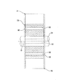
図1A及び図1AのI-I断面を示す図1Bは、本実施形態における製造方法及び製造装置によって製造された磁石片から構成される界磁極用磁石体80を適用した永久磁石埋込型回転電機A(以下、単に「回転電機A」という)を示している。
図8A~図8Cは、本発明を適用した回転電機に配設される界磁極用磁石体を構成する磁石片を製造する製造方法及び製造装置の第2実施形態を示し、図8Aは磁石片を製造する製造装置を示す概略構成図、図8B,図8Cはその作動状態を示す説明図である。本実施形態においては、磁石体及び磁石片を押さえる磁石押さえを、気体(空気)を噴出する手段により形成する構成を第1実施形態に追加したものである。なお、第1実施形態と同一装置には同一符号を付してその説明を省略ないし簡略化する。
Claims (6)
- 回転電機に配設される界磁極用磁石体を構成する磁石片を、永久磁石体を割断して製造する製造方法であって、
劣化防止用のコーティング膜が表面に施された前記永久磁石体を、その割断予定部位が当該永久磁石体を支持する2つの支点間に位置するように位置決めする工程と、
前記永久磁石体の割断予定部位を押圧して割断後磁石体と磁石片とに割断する割断工程と、
前記割断工程により割断された前記磁石片の割断面側とは反対側の端部を、前記割断予定部位を押圧する側から押さえて前記割断後磁石体との間のコーティング膜の切断を行うコーティング膜切断工程と、を備える製造方法。 - 請求項1に記載の製造方法であって、
前記コーティング膜切断工程は、前記磁石片の割断面側とは反対側端部を弾性体で押さえて実行される製造方法。 - 請求項1に記載の製造方法であって、
前記コーティング膜切断工程は、前記磁石片の割断面側とは反対側端部を空気噴流で押さえて実行される製造方法。 - 回転電機に配設される界磁極用磁石体を構成する磁石片を、永久磁石体を割断して製造する製造装置であって、
劣化防止用のコーティング膜が表面に施された前記永久磁石体を、その割断予定部位の両側において2つの支点で支持する支持部と、
前記両支点間の前記永久磁石体の割断予定部位を押圧して、前記磁石体を割断後磁石体と磁石片とに割断する割断手段と、
前記割断手段により割断された前記磁石片の割断面側とは反対側の端部を、前記割断予定部位を押圧する側から押さえて前記割断後磁石体との間のコーティング膜の切断を行うコーティング膜切断手段と、を備える製造装置。 - 請求項4に記載の製造装置であって、
前記コーティング膜切断手段は、前記磁石片の割断面側とは反対側端部を弾性体で押さえて実行される製造装置。 - 請求項4に記載の製造装置であって、
前記コーティング膜切断手段は、前記磁石片の割断面側とは反対側端部を空気噴流で押さえて実行される製造装置。
Priority Applications (4)
| Application Number | Priority Date | Filing Date | Title |
|---|---|---|---|
| CN201480052190.XA CN105594107B (zh) | 2013-10-09 | 2014-07-29 | 制造用于构成被配设于旋转电机的场磁极用磁体的磁体片的制造方法和制造装置 |
| US15/027,470 US10279504B2 (en) | 2013-10-09 | 2014-07-29 | Manufacture method and manufacturing device for manufacturing magnet piece constituting magnet body for field pole disposed on rotating electric machine |
| JP2015541462A JP6112216B2 (ja) | 2013-10-09 | 2014-07-29 | 回転電機に配設される界磁極用磁石体を構成する磁石片を製造する製造方法及び製造装置 |
| EP14851916.8A EP3057207B1 (en) | 2013-10-09 | 2014-07-29 | Method and device for manufacturing magnet pieces configuring a field pole magnet to be arranged in a rotary machine |
Applications Claiming Priority (2)
| Application Number | Priority Date | Filing Date | Title |
|---|---|---|---|
| JP2013-211769 | 2013-10-09 | ||
| JP2013211769 | 2013-10-09 |
Publications (1)
| Publication Number | Publication Date |
|---|---|
| WO2015052976A1 true WO2015052976A1 (ja) | 2015-04-16 |
Family
ID=52812797
Family Applications (1)
| Application Number | Title | Priority Date | Filing Date |
|---|---|---|---|
| PCT/JP2014/069970 Ceased WO2015052976A1 (ja) | 2013-10-09 | 2014-07-29 | 回転電機に配設される界磁極用磁石体を構成する磁石片を製造する製造方法及び製造装置 |
Country Status (5)
| Country | Link |
|---|---|
| US (1) | US10279504B2 (ja) |
| EP (1) | EP3057207B1 (ja) |
| JP (1) | JP6112216B2 (ja) |
| CN (1) | CN105594107B (ja) |
| WO (1) | WO2015052976A1 (ja) |
Families Citing this family (5)
| Publication number | Priority date | Publication date | Assignee | Title |
|---|---|---|---|---|
| US10374477B2 (en) * | 2017-03-17 | 2019-08-06 | General Electric Company | Electric machine with separable magnet carrier |
| FR3066488B1 (fr) * | 2017-05-19 | 2022-03-04 | Saint Gobain | Procede de rompage d'une feuille de verre |
| US12217908B2 (en) * | 2020-01-07 | 2025-02-04 | Bomatec Management Ag | Permanent magnet for use in an electric machine with one or more grooves |
| US11428160B2 (en) | 2020-12-31 | 2022-08-30 | General Electric Company | Gas turbine engine with interdigitated turbine and gear assembly |
| US12009711B2 (en) * | 2021-03-16 | 2024-06-11 | Toyota Jidosha Kabushiki Kaisha | Method of manufacturing magnets and method of manufacturing rotor |
Citations (5)
| Publication number | Priority date | Publication date | Assignee | Title |
|---|---|---|---|---|
| JP2009142081A (ja) | 2007-12-06 | 2009-06-25 | Toyota Motor Corp | 永久磁石とその製造方法、およびロータとipmモータ |
| WO2010038748A1 (ja) * | 2008-10-02 | 2010-04-08 | 日産自動車株式会社 | 界磁極用磁石体、この界磁用磁石体の作製方法、及び永久磁石型回転電機 |
| WO2013108772A1 (ja) * | 2012-01-16 | 2013-07-25 | 日産自動車株式会社 | 界磁極用磁石体の製造装置およびその製造方法 |
| JP2013172554A (ja) * | 2012-02-21 | 2013-09-02 | Nissan Motor Co Ltd | 界磁極用磁石体を構成する磁石片の製造装置 |
| WO2014007038A1 (ja) * | 2012-07-02 | 2014-01-09 | 日産自動車株式会社 | 界磁極用磁石体を構成する磁石片の製造装置及びその製造方法 |
Family Cites Families (12)
| Publication number | Priority date | Publication date | Assignee | Title |
|---|---|---|---|---|
| JP5262643B2 (ja) * | 2008-12-04 | 2013-08-14 | 信越化学工業株式会社 | Nd系焼結磁石及びその製造方法 |
| JP5614096B2 (ja) * | 2010-05-19 | 2014-10-29 | 日産自動車株式会社 | 回転電機のロータコアに埋込まれる永久磁石およびその製造方法 |
| WO2011158710A1 (ja) * | 2010-06-17 | 2011-12-22 | 日産自動車株式会社 | 回転電機に配設される永久磁石の製造装置およびその製造方法 |
| CN102754307B (zh) * | 2011-02-02 | 2015-05-06 | 丰田自动车株式会社 | 永久磁铁、用于马达的转子或定子、旋转电机 |
| CN103650304B (zh) | 2011-07-27 | 2016-01-20 | 日产自动车株式会社 | 励磁磁极用磁体的制造装置及其制造方法 |
| JP6393019B2 (ja) | 2011-09-26 | 2018-09-19 | 日産自動車株式会社 | 界磁極用磁石体の製造装置およびその製造方法 |
| JP5867036B2 (ja) * | 2011-12-07 | 2016-02-24 | 日産自動車株式会社 | 界磁極用磁石体の製造装置およびその製造方法 |
| JP5929153B2 (ja) * | 2011-12-14 | 2016-06-01 | 日産自動車株式会社 | 界磁極用磁石体の製造装置およびその製造方法 |
| JP5761384B2 (ja) * | 2012-02-01 | 2015-08-12 | 日産自動車株式会社 | 界磁極用磁石体を構成する磁石片の製造方法 |
| JP5994280B2 (ja) | 2012-02-21 | 2016-09-21 | 日産自動車株式会社 | 界磁極用磁石体を構成する磁石片の製造方法および製造装置 |
| JP5919888B2 (ja) | 2012-03-01 | 2016-05-18 | 日産自動車株式会社 | 回転電機に配設される界磁極用磁石体を構成する磁石片を、永久磁石体を割断して製造する割断方法及び割断装置 |
| EP3041114B1 (en) | 2013-08-29 | 2019-07-24 | Nissan Motor Co., Ltd. | Cutting method and cutting device for manufacturing magnet piece constituting magnet body for field pole to be arranged in rotary electric machine |
-
2014
- 2014-07-29 US US15/027,470 patent/US10279504B2/en active Active
- 2014-07-29 JP JP2015541462A patent/JP6112216B2/ja active Active
- 2014-07-29 CN CN201480052190.XA patent/CN105594107B/zh active Active
- 2014-07-29 WO PCT/JP2014/069970 patent/WO2015052976A1/ja not_active Ceased
- 2014-07-29 EP EP14851916.8A patent/EP3057207B1/en active Active
Patent Citations (5)
| Publication number | Priority date | Publication date | Assignee | Title |
|---|---|---|---|---|
| JP2009142081A (ja) | 2007-12-06 | 2009-06-25 | Toyota Motor Corp | 永久磁石とその製造方法、およびロータとipmモータ |
| WO2010038748A1 (ja) * | 2008-10-02 | 2010-04-08 | 日産自動車株式会社 | 界磁極用磁石体、この界磁用磁石体の作製方法、及び永久磁石型回転電機 |
| WO2013108772A1 (ja) * | 2012-01-16 | 2013-07-25 | 日産自動車株式会社 | 界磁極用磁石体の製造装置およびその製造方法 |
| JP2013172554A (ja) * | 2012-02-21 | 2013-09-02 | Nissan Motor Co Ltd | 界磁極用磁石体を構成する磁石片の製造装置 |
| WO2014007038A1 (ja) * | 2012-07-02 | 2014-01-09 | 日産自動車株式会社 | 界磁極用磁石体を構成する磁石片の製造装置及びその製造方法 |
Also Published As
| Publication number | Publication date |
|---|---|
| CN105594107B (zh) | 2019-07-16 |
| EP3057207A4 (en) | 2016-09-14 |
| CN105594107A (zh) | 2016-05-18 |
| JPWO2015052976A1 (ja) | 2017-03-09 |
| EP3057207B1 (en) | 2018-10-10 |
| US20160243719A1 (en) | 2016-08-25 |
| EP3057207A1 (en) | 2016-08-17 |
| JP6112216B2 (ja) | 2017-04-12 |
| US10279504B2 (en) | 2019-05-07 |
Similar Documents
| Publication | Publication Date | Title |
|---|---|---|
| JP6112216B2 (ja) | 回転電機に配設される界磁極用磁石体を構成する磁石片を製造する製造方法及び製造装置 | |
| CN101064274B (zh) | 结合在晶片上的粘结膜的分断方法 | |
| JP4909657B2 (ja) | サファイア基板の加工方法 | |
| US8415232B2 (en) | Dividing method for wafer having die bonding film attached to the back side thereof | |
| JP5850152B2 (ja) | 界磁極用磁石体を構成する磁石片の製造装置及びその製造方法 | |
| JP6079887B2 (ja) | 回転電機に配設される界磁極用磁石体を構成する磁石片を製造する割断方法及び割断装置 | |
| JP5800645B2 (ja) | チップ間隔維持方法 | |
| JP2006049591A (ja) | ウエーハに貼着された接着フィルムの破断方法および破断装置 | |
| EP3765217B1 (en) | Laser assisted machining of electric motor cores | |
| JP2013055138A (ja) | チップ間隔維持方法 | |
| JP4927582B2 (ja) | ウエーハの裏面に装着された接着フィルムの破断方法 | |
| CN103650304A (zh) | 励磁磁极用磁体的制造装置及其制造方法 | |
| JP2011183477A (ja) | マルチワイヤ放電加工装置及び炭化ケイ素板の製造方法 | |
| WO2016079850A1 (ja) | 積層コア製造装置および積層コア製造方法、並びに積層コア | |
| JP5849774B2 (ja) | 回転電機に配設される界磁極用磁石体を構成する磁石片を、永久磁石体を割断して製造する割断方法及び割断装置 | |
| JP2007134510A (ja) | ウェーハマウンタ装置 | |
| JP5489808B2 (ja) | 半導体デバイスの製造方法 | |
| JP5919888B2 (ja) | 回転電機に配設される界磁極用磁石体を構成する磁石片を、永久磁石体を割断して製造する割断方法及び割断装置 | |
| JP2012004446A (ja) | ダイシング方法及びダイシング装置 | |
| WO2013125513A1 (ja) | 界磁極用磁石体を構成する磁石片の製造方法および製造装置 | |
| JP2015217507A (ja) | ウエーハの製造方法 | |
| JP2018058730A (ja) | 長尺脆性部材の切断方法、短尺脆性部材、および長尺脆性部材の切断装置 |
Legal Events
| Date | Code | Title | Description |
|---|---|---|---|
| 121 | Ep: the epo has been informed by wipo that ep was designated in this application |
Ref document number: 14851916 Country of ref document: EP Kind code of ref document: A1 |
|
| ENP | Entry into the national phase |
Ref document number: 2015541462 Country of ref document: JP Kind code of ref document: A |
|
| REEP | Request for entry into the european phase |
Ref document number: 2014851916 Country of ref document: EP |
|
| WWE | Wipo information: entry into national phase |
Ref document number: 15027470 Country of ref document: US Ref document number: 2014851916 Country of ref document: EP |
|
| NENP | Non-entry into the national phase |
Ref country code: DE |