WO2015053169A1 - 車両の運動制御装置 - Google Patents
車両の運動制御装置 Download PDFInfo
- Publication number
- WO2015053169A1 WO2015053169A1 PCT/JP2014/076489 JP2014076489W WO2015053169A1 WO 2015053169 A1 WO2015053169 A1 WO 2015053169A1 JP 2014076489 W JP2014076489 W JP 2014076489W WO 2015053169 A1 WO2015053169 A1 WO 2015053169A1
- Authority
- WO
- WIPO (PCT)
- Prior art keywords
- vehicle
- motion control
- control device
- deceleration
- control
- Prior art date
- Legal status (The legal status is an assumption and is not a legal conclusion. Google has not performed a legal analysis and makes no representation as to the accuracy of the status listed.)
- Ceased
Links
Images














Classifications
-
- B—PERFORMING OPERATIONS; TRANSPORTING
- B60—VEHICLES IN GENERAL
- B60W—CONJOINT CONTROL OF VEHICLE SUB-UNITS OF DIFFERENT TYPE OR DIFFERENT FUNCTION; CONTROL SYSTEMS SPECIALLY ADAPTED FOR HYBRID VEHICLES; ROAD VEHICLE DRIVE CONTROL SYSTEMS FOR PURPOSES NOT RELATED TO THE CONTROL OF A PARTICULAR SUB-UNIT
- B60W30/00—Purposes of road vehicle drive control systems not related to the control of a particular sub-unit, e.g. of systems using conjoint control of vehicle sub-units
- B60W30/08—Active safety systems predicting or avoiding probable or impending collision or attempting to minimise its consequences
- B60W30/09—Taking automatic action to avoid collision, e.g. braking and steering
-
- B—PERFORMING OPERATIONS; TRANSPORTING
- B60—VEHICLES IN GENERAL
- B60T—VEHICLE BRAKE CONTROL SYSTEMS OR PARTS THEREOF; BRAKE CONTROL SYSTEMS OR PARTS THEREOF, IN GENERAL; ARRANGEMENT OF BRAKING ELEMENTS ON VEHICLES IN GENERAL; PORTABLE DEVICES FOR PREVENTING UNWANTED MOVEMENT OF VEHICLES; VEHICLE MODIFICATIONS TO FACILITATE COOLING OF BRAKES
- B60T7/00—Brake-action initiating means
- B60T7/12—Brake-action initiating means for automatic initiation; for initiation not subject to will of driver or passenger
-
- B—PERFORMING OPERATIONS; TRANSPORTING
- B60—VEHICLES IN GENERAL
- B60T—VEHICLE BRAKE CONTROL SYSTEMS OR PARTS THEREOF; BRAKE CONTROL SYSTEMS OR PARTS THEREOF, IN GENERAL; ARRANGEMENT OF BRAKING ELEMENTS ON VEHICLES IN GENERAL; PORTABLE DEVICES FOR PREVENTING UNWANTED MOVEMENT OF VEHICLES; VEHICLE MODIFICATIONS TO FACILITATE COOLING OF BRAKES
- B60T7/00—Brake-action initiating means
- B60T7/12—Brake-action initiating means for automatic initiation; for initiation not subject to will of driver or passenger
- B60T7/22—Brake-action initiating means for automatic initiation; for initiation not subject to will of driver or passenger initiated by contact of vehicle, e.g. bumper, with an external object, e.g. another vehicle, or by means of contactless obstacle detectors mounted on the vehicle
-
- B—PERFORMING OPERATIONS; TRANSPORTING
- B60—VEHICLES IN GENERAL
- B60T—VEHICLE BRAKE CONTROL SYSTEMS OR PARTS THEREOF; BRAKE CONTROL SYSTEMS OR PARTS THEREOF, IN GENERAL; ARRANGEMENT OF BRAKING ELEMENTS ON VEHICLES IN GENERAL; PORTABLE DEVICES FOR PREVENTING UNWANTED MOVEMENT OF VEHICLES; VEHICLE MODIFICATIONS TO FACILITATE COOLING OF BRAKES
- B60T8/00—Arrangements for adjusting wheel-braking force to meet varying vehicular or ground-surface conditions, e.g. limiting or varying distribution of braking force
- B60T8/17—Using electrical or electronic regulation means to control braking
- B60T8/1755—Brake regulation specially adapted to control the stability of the vehicle, e.g. taking into account yaw rate or transverse acceleration in a curve
- B60T8/17558—Brake regulation specially adapted to control the stability of the vehicle, e.g. taking into account yaw rate or transverse acceleration in a curve specially adapted for collision avoidance or collision mitigation
-
- B—PERFORMING OPERATIONS; TRANSPORTING
- B60—VEHICLES IN GENERAL
- B60W—CONJOINT CONTROL OF VEHICLE SUB-UNITS OF DIFFERENT TYPE OR DIFFERENT FUNCTION; CONTROL SYSTEMS SPECIALLY ADAPTED FOR HYBRID VEHICLES; ROAD VEHICLE DRIVE CONTROL SYSTEMS FOR PURPOSES NOT RELATED TO THE CONTROL OF A PARTICULAR SUB-UNIT
- B60W10/00—Conjoint control of vehicle sub-units of different type or different function
- B60W10/18—Conjoint control of vehicle sub-units of different type or different function including control of braking systems
-
- B—PERFORMING OPERATIONS; TRANSPORTING
- B60—VEHICLES IN GENERAL
- B60W—CONJOINT CONTROL OF VEHICLE SUB-UNITS OF DIFFERENT TYPE OR DIFFERENT FUNCTION; CONTROL SYSTEMS SPECIALLY ADAPTED FOR HYBRID VEHICLES; ROAD VEHICLE DRIVE CONTROL SYSTEMS FOR PURPOSES NOT RELATED TO THE CONTROL OF A PARTICULAR SUB-UNIT
- B60W10/00—Conjoint control of vehicle sub-units of different type or different function
- B60W10/20—Conjoint control of vehicle sub-units of different type or different function including control of steering systems
-
- B—PERFORMING OPERATIONS; TRANSPORTING
- B60—VEHICLES IN GENERAL
- B60W—CONJOINT CONTROL OF VEHICLE SUB-UNITS OF DIFFERENT TYPE OR DIFFERENT FUNCTION; CONTROL SYSTEMS SPECIALLY ADAPTED FOR HYBRID VEHICLES; ROAD VEHICLE DRIVE CONTROL SYSTEMS FOR PURPOSES NOT RELATED TO THE CONTROL OF A PARTICULAR SUB-UNIT
- B60W30/00—Purposes of road vehicle drive control systems not related to the control of a particular sub-unit, e.g. of systems using conjoint control of vehicle sub-units
- B60W30/02—Control of vehicle driving stability
-
- B—PERFORMING OPERATIONS; TRANSPORTING
- B60—VEHICLES IN GENERAL
- B60W—CONJOINT CONTROL OF VEHICLE SUB-UNITS OF DIFFERENT TYPE OR DIFFERENT FUNCTION; CONTROL SYSTEMS SPECIALLY ADAPTED FOR HYBRID VEHICLES; ROAD VEHICLE DRIVE CONTROL SYSTEMS FOR PURPOSES NOT RELATED TO THE CONTROL OF A PARTICULAR SUB-UNIT
- B60W30/00—Purposes of road vehicle drive control systems not related to the control of a particular sub-unit, e.g. of systems using conjoint control of vehicle sub-units
- B60W30/02—Control of vehicle driving stability
- B60W30/045—Improving turning performance
-
- B—PERFORMING OPERATIONS; TRANSPORTING
- B60—VEHICLES IN GENERAL
- B60W—CONJOINT CONTROL OF VEHICLE SUB-UNITS OF DIFFERENT TYPE OR DIFFERENT FUNCTION; CONTROL SYSTEMS SPECIALLY ADAPTED FOR HYBRID VEHICLES; ROAD VEHICLE DRIVE CONTROL SYSTEMS FOR PURPOSES NOT RELATED TO THE CONTROL OF A PARTICULAR SUB-UNIT
- B60W30/00—Purposes of road vehicle drive control systems not related to the control of a particular sub-unit, e.g. of systems using conjoint control of vehicle sub-units
- B60W30/18—Propelling the vehicle
- B60W30/18009—Propelling the vehicle related to particular drive situations
- B60W30/18145—Cornering
-
- B—PERFORMING OPERATIONS; TRANSPORTING
- B62—LAND VEHICLES FOR TRAVELLING OTHERWISE THAN ON RAILS
- B62D—MOTOR VEHICLES; TRAILERS
- B62D15/00—Steering not otherwise provided for
- B62D15/02—Steering position indicators ; Steering position determination; Steering aids
- B62D15/025—Active steering aids, e.g. helping the driver by actively influencing the steering system after environment evaluation
- B62D15/0265—Automatic obstacle avoidance by steering
-
- B—PERFORMING OPERATIONS; TRANSPORTING
- B60—VEHICLES IN GENERAL
- B60T—VEHICLE BRAKE CONTROL SYSTEMS OR PARTS THEREOF; BRAKE CONTROL SYSTEMS OR PARTS THEREOF, IN GENERAL; ARRANGEMENT OF BRAKING ELEMENTS ON VEHICLES IN GENERAL; PORTABLE DEVICES FOR PREVENTING UNWANTED MOVEMENT OF VEHICLES; VEHICLE MODIFICATIONS TO FACILITATE COOLING OF BRAKES
- B60T2201/00—Particular use of vehicle brake systems; Special systems using also the brakes; Special software modules within the brake system controller
- B60T2201/02—Active or adaptive cruise control system; Distance control
- B60T2201/022—Collision avoidance systems
-
- B—PERFORMING OPERATIONS; TRANSPORTING
- B60—VEHICLES IN GENERAL
- B60T—VEHICLE BRAKE CONTROL SYSTEMS OR PARTS THEREOF; BRAKE CONTROL SYSTEMS OR PARTS THEREOF, IN GENERAL; ARRANGEMENT OF BRAKING ELEMENTS ON VEHICLES IN GENERAL; PORTABLE DEVICES FOR PREVENTING UNWANTED MOVEMENT OF VEHICLES; VEHICLE MODIFICATIONS TO FACILITATE COOLING OF BRAKES
- B60T2230/00—Monitoring, detecting special vehicle behaviour; Counteracting thereof
- B60T2230/04—Jerk, soft-stop; Anti-jerk, reduction of pitch or nose-dive when braking
-
- B—PERFORMING OPERATIONS; TRANSPORTING
- B60—VEHICLES IN GENERAL
- B60W—CONJOINT CONTROL OF VEHICLE SUB-UNITS OF DIFFERENT TYPE OR DIFFERENT FUNCTION; CONTROL SYSTEMS SPECIALLY ADAPTED FOR HYBRID VEHICLES; ROAD VEHICLE DRIVE CONTROL SYSTEMS FOR PURPOSES NOT RELATED TO THE CONTROL OF A PARTICULAR SUB-UNIT
- B60W2510/00—Input parameters relating to a particular sub-units
- B60W2510/18—Braking system
-
- B—PERFORMING OPERATIONS; TRANSPORTING
- B60—VEHICLES IN GENERAL
- B60W—CONJOINT CONTROL OF VEHICLE SUB-UNITS OF DIFFERENT TYPE OR DIFFERENT FUNCTION; CONTROL SYSTEMS SPECIALLY ADAPTED FOR HYBRID VEHICLES; ROAD VEHICLE DRIVE CONTROL SYSTEMS FOR PURPOSES NOT RELATED TO THE CONTROL OF A PARTICULAR SUB-UNIT
- B60W2510/00—Input parameters relating to a particular sub-units
- B60W2510/20—Steering systems
-
- B—PERFORMING OPERATIONS; TRANSPORTING
- B60—VEHICLES IN GENERAL
- B60W—CONJOINT CONTROL OF VEHICLE SUB-UNITS OF DIFFERENT TYPE OR DIFFERENT FUNCTION; CONTROL SYSTEMS SPECIALLY ADAPTED FOR HYBRID VEHICLES; ROAD VEHICLE DRIVE CONTROL SYSTEMS FOR PURPOSES NOT RELATED TO THE CONTROL OF A PARTICULAR SUB-UNIT
- B60W2520/00—Input parameters relating to overall vehicle dynamics
-
- B—PERFORMING OPERATIONS; TRANSPORTING
- B60—VEHICLES IN GENERAL
- B60W—CONJOINT CONTROL OF VEHICLE SUB-UNITS OF DIFFERENT TYPE OR DIFFERENT FUNCTION; CONTROL SYSTEMS SPECIALLY ADAPTED FOR HYBRID VEHICLES; ROAD VEHICLE DRIVE CONTROL SYSTEMS FOR PURPOSES NOT RELATED TO THE CONTROL OF A PARTICULAR SUB-UNIT
- B60W2520/00—Input parameters relating to overall vehicle dynamics
- B60W2520/10—Longitudinal speed
-
- B—PERFORMING OPERATIONS; TRANSPORTING
- B60—VEHICLES IN GENERAL
- B60W—CONJOINT CONTROL OF VEHICLE SUB-UNITS OF DIFFERENT TYPE OR DIFFERENT FUNCTION; CONTROL SYSTEMS SPECIALLY ADAPTED FOR HYBRID VEHICLES; ROAD VEHICLE DRIVE CONTROL SYSTEMS FOR PURPOSES NOT RELATED TO THE CONTROL OF A PARTICULAR SUB-UNIT
- B60W2520/00—Input parameters relating to overall vehicle dynamics
- B60W2520/10—Longitudinal speed
- B60W2520/105—Longitudinal acceleration
-
- B—PERFORMING OPERATIONS; TRANSPORTING
- B60—VEHICLES IN GENERAL
- B60W—CONJOINT CONTROL OF VEHICLE SUB-UNITS OF DIFFERENT TYPE OR DIFFERENT FUNCTION; CONTROL SYSTEMS SPECIALLY ADAPTED FOR HYBRID VEHICLES; ROAD VEHICLE DRIVE CONTROL SYSTEMS FOR PURPOSES NOT RELATED TO THE CONTROL OF A PARTICULAR SUB-UNIT
- B60W2520/00—Input parameters relating to overall vehicle dynamics
- B60W2520/12—Lateral speed
- B60W2520/125—Lateral acceleration
-
- B—PERFORMING OPERATIONS; TRANSPORTING
- B60—VEHICLES IN GENERAL
- B60W—CONJOINT CONTROL OF VEHICLE SUB-UNITS OF DIFFERENT TYPE OR DIFFERENT FUNCTION; CONTROL SYSTEMS SPECIALLY ADAPTED FOR HYBRID VEHICLES; ROAD VEHICLE DRIVE CONTROL SYSTEMS FOR PURPOSES NOT RELATED TO THE CONTROL OF A PARTICULAR SUB-UNIT
- B60W2520/00—Input parameters relating to overall vehicle dynamics
- B60W2520/14—Yaw
-
- B—PERFORMING OPERATIONS; TRANSPORTING
- B60—VEHICLES IN GENERAL
- B60W—CONJOINT CONTROL OF VEHICLE SUB-UNITS OF DIFFERENT TYPE OR DIFFERENT FUNCTION; CONTROL SYSTEMS SPECIALLY ADAPTED FOR HYBRID VEHICLES; ROAD VEHICLE DRIVE CONTROL SYSTEMS FOR PURPOSES NOT RELATED TO THE CONTROL OF A PARTICULAR SUB-UNIT
- B60W2556/00—Input parameters relating to data
-
- B—PERFORMING OPERATIONS; TRANSPORTING
- B60—VEHICLES IN GENERAL
- B60Y—INDEXING SCHEME RELATING TO ASPECTS CROSS-CUTTING VEHICLE TECHNOLOGY
- B60Y2300/00—Purposes or special features of road vehicle drive control systems
- B60Y2300/08—Predicting or avoiding probable or impending collision
- B60Y2300/09—Taking automatic action to avoid collision, e.g. braking or steering
-
- B—PERFORMING OPERATIONS; TRANSPORTING
- B60—VEHICLES IN GENERAL
- B60Y—INDEXING SCHEME RELATING TO ASPECTS CROSS-CUTTING VEHICLE TECHNOLOGY
- B60Y2300/00—Purposes or special features of road vehicle drive control systems
- B60Y2300/80—Control of differentials
- B60Y2300/82—Torque vectoring
Definitions
- the present invention relates to a vehicle motion control device for controlling longitudinal acceleration and yawing moment of a vehicle.
- Patent Document 1 a control object in front of the host vehicle is recognized based on a road environment in front captured by a camera, a brake intervention distance is set based on a relative relationship between the host vehicle and the control object, and A technique of an automatic braking control device that determines execution of braking control when the relative distance to the controlled object is equal to or less than the braking intervention distance and that performs automatic braking intervention is disclosed.
- the input lateral jerk (Gy_dot) of the vehicle is determined from the speed (V) and the lateral acceleration (Gy) and multiplied by a prestored gain (KGyV).
- a vehicle motion control method is disclosed that generates a control command for controlling the longitudinal acceleration of a vehicle based on the value and outputs the generated control command.
- the locus of the combined acceleration vector (G) of longitudinal acceleration and lateral acceleration is oriented so as to draw a smooth curve in a coordinate system with a fixed vehicle center of gravity (Vectoring), and G-Vectoring control (GVC: G-Vectoring Control).
- Vectoring vehicle center of gravity
- GVC G-Vectoring Control
- Patent Document 2 has means for detecting the longitudinal speed (V) of the vehicle and means for training the lateral jerk (Gy_dot) of the vehicle.
- the jerk is divided by the speed.
- a vehicle motion control apparatus is disclosed that controls the yaw moment of the vehicle based on the measured value. This method is not model-following feedback control in which the yaw moment is controlled based on vehicle side slip information or the like, and control is performed so that the error between the yaw motion of the vehicle and the yaw motion prediction of the reference model is reduced.
- Moment + It is called Moment + (M +) because it adds a little assist moment to the turning acceleration yaw moment generated by steering and the restored yaw moment originally possessed by the vehicle (Non-patent Document 2).
- an electric inter-axle torque generator yaw moment generator as shown in Patent Document 3 may be used.
- the turning ability of the vehicle can be improved with less acceleration / deceleration than GVC.
- a torque difference that is, a so-called counter torque
- a yaw moment can be directly applied to the vehicle and acceleration / deceleration is caused in the vehicle.
- deceleration is generated when a yaw moment is applied to a vehicle by applying different deceleration forces to the left and right wheels by using a skid prevention device (Electronic Stability Control: ESC) that is required to be installed recently.
- ESC Electronic Stability Control
- the braking control unit checks whether or not the steering angle
- a prohibit timer t ⁇ that defines the time is set.
- the braking control unit checks whether or not the steering angular velocity
- (
- a vehicle motion control apparatus includes a danger potential estimation unit that estimates a danger potential of a vehicle based on input external world information and vehicle information, a lateral jerk of the vehicle, and a predetermined value.
- a vehicle longitudinal motion control unit that generates a vehicle longitudinal motion control command based on the gain
- a vehicle yawing motion control unit that generates a vehicle yawing motion control command based on the lateral jerk and a predetermined gain
- a ratio adjustment unit that adjusts a ratio between the vehicle longitudinal motion control command and the vehicle yawing motion control command, and the ratio adjustment unit adjusts the ratio based on the risk potential estimated by the risk potential estimation unit.
- the configuration is as follows.
- GVC G-Vectoring control
- M + movement of a moment plus (M +) control law. It is a figure which shows a motion when the force at right angles to the speed direction acts on the mass point. It is a figure which shows the locus
- FIG. 1 is a diagram showing an overall configuration of a vehicle motion control device according to the present invention. It is a figure which shows the internal structure of an ADAS controller and a brake controller.
- It has at least a mode that controls the longitudinal acceleration / deceleration linked to the lateral movement of the vehicle and a mode that controls the yaw moment linked to the lateral movement of the vehicle.
- the emergency avoidance performance is improved by reducing the operating ratio of the control, greatly reducing the speed, and maximizing the direction component (direction away from the obstacle) opposite to the speed of the resultant force applied to the vehicle.
- Non-Patent Document 1 discloses a method for improving the maneuverability and stability of a vehicle by generating a load movement between front wheels and rear wheels by automatically accelerating and decelerating in conjunction with a lateral movement by a steering wheel operation. It is shown.
- the specific acceleration / deceleration command value (target longitudinal acceleration Gxc) is as shown in Equation 1 below.
- Gy is the vehicle lateral acceleration
- Gy_dot is the vehicle lateral jerk
- Cxy is the gain
- T is the first-order lag time constant
- s is the Laplace operator
- Gx_DC is the acceleration / deceleration command not linked to the lateral motion.
- Non-Patent Document 1 It has been confirmed in Non-Patent Document 1 that it is possible to simulate a part of the linkage control strategy of the expert driver's side and back-and-forth movement and to improve the maneuverability and stability of the vehicle.
- G Gx_DC in this equation is a deceleration component (offset) that is not linked to lateral motion. This term is required when there is a foreseeable deceleration when there is a corner ahead or when there is a section speed command.
- the sgn (signum) term is a term provided so that the above operation can be obtained for both the right corner and the left corner. Specifically, the vehicle decelerates when turning in at the start of steering, and can stop when decelerating (because the lateral jerk becomes zero), and can perform an operation of accelerating when exiting the corner at the start of steering return.
- G the combined acceleration of longitudinal acceleration and lateral acceleration
- G-Vectoring control This is called “G-Vectoring control” because it is directed to make a transition (Vectoring).
- Fig. 1 assumes general driving scenes of entering and exiting a corner, such as straight path A, transition section B, steady turning section C, transition section D, and straight section E. At this time, the acceleration / deceleration operation by the driver is not performed.
- FIG. 2 is a time calendar waveform showing the steering angle, lateral acceleration, lateral jerk, acceleration / deceleration command calculated by Equation 1, braking of four wheels, and driving force.
- the braking force and driving force are distributed so that the front outer wheel and the front inner wheel, the rear outer wheel and the rear inner wheel have the same value on the left and right (inner and outer).
- the braking / driving force is a general term for the force generated in the vehicle front-rear direction of each wheel
- the braking force is a force in the direction of decelerating the vehicle
- the driving force is defined as a force in the direction of accelerating the vehicle.
- the lateral acceleration Gy of the vehicle increases as the driver gradually increases steering.
- the lateral jerk Gy_dot takes a positive value while the lateral acceleration in the vicinity of the point 2 is increasing (returns to zero at the time point 3 at which the lateral acceleration increase ends).
- a deceleration (Gxc is negative) command is issued to the controlled vehicle as the lateral acceleration Gy increases.
- a braking force (minus sign) having substantially the same magnitude is applied to each of the front outer, front inner, rear outer, and rear inner wheels.
- the lateral acceleration Gy of the vehicle decreases due to the driver's steering return operation.
- the lateral jerk Gy_dot of the vehicle is negative, and the acceleration command Gxc is generated in the control vehicle from Equation 1.
- a driving force (plus sign) having substantially the same magnitude is applied to the front outer, front inner, rear outer, and rear inner wheels.
- the lateral jerk Gy is 0 and the lateral jerk Gy_dot is also zero, so acceleration / deceleration control is not performed.
- the vehicle decelerates from the turn-in at the start of steering (point 1) to the clipping point (point 3), stops during a steady circular turn (points 3 to 5), and starts steering return (points). Accelerate when exiting the corner from 5) (point 7).
- G-Vectoring control is applied to the vehicle, the driver can realize acceleration / deceleration motion linked to lateral motion only by steering for turning.
- the longitudinal acceleration is plotted on the horizontal axis and the horizontal acceleration is plotted on the vertical axis, it is a characteristic that transitions into a smooth curve (draws a circle). It becomes a kind of exercise.
- the acceleration / deceleration command of the present invention is generated in this diagram so as to make a curved transition with the passage of time.
- the curved transition is a clockwise transition as shown in FIG. 1, and the right corner is a transition path inverted with respect to the Gx axis, and the transition direction is counterclockwise.
- FIG. 3 is a diagram showing a normal gain running in the same situation as FIGS. 1 and 2 and a turning situation in a high gain state where the gain is increased. Increasing the gain increases the deceleration at the start of the turn, reduces the vehicle speed compared to the normal gain, reduces the lateral acceleration even for the same steering, and improves the safety during turning.
- a comparison of the “gg” diagram with the strong gain is shown in FIG. The curve of the diagram is maintained, but the shape is swollen in the Gx direction, and the Gy direction is affected by the decrease in speed and tends to be slightly narrowed.
- This control uses the value obtained by multiplying the vehicle lateral jerk by the gain Cmn as in GVC, considering the first-order lag term and the sign function for the left and right motions as shown in Equation 2.
- Non-patent Document 3 Makoto Yamamon, Keiichiro Nagatsuka: Yaw moment control method based on vehicle lateral jerk (2), Automobile Engineering Society Academic Lecture Preprints: 60-13 pages: 21-26, 2013).
- the method of adding the control moment inversely proportional to the speed as shown in the following equation 3 is particularly effective for a vehicle with an oversteer.
- a method may be used in which a speed lower limiter for stopping the control is provided or the control amount is fixed at an extremely low speed.
- M + control since yawing motion control is directly controlled, there is a case where a feeling of rotating rather than turning (so-called amusement park tea cup feeling) may occur.
- M + control is realized by brake control by ESC, in order to obtain the same yaw response, it is possible to realize it with less deceleration than GVC.
- the deceleration at that time is also substantially proportional to the lateral jerk, resulting in the same deceleration (combined acceleration vectoring) as when GVC is implemented with low gain, and an improvement in ride comfort can be expected.
- This section describes the effects of longitudinal acceleration control and yaw moment control on vehicle behavior at the initial stage of avoidance, which is a dominant factor for improving emergency avoidance performance, and provides guidelines on how to allocate GVC and M + control proportionately. I will follow it.
- the vehicle at the start of turning is regarded as a mass point (a yawing motion is not considered for the time being), and the influence of deceleration is analyzed analytically.
- the ratio distribution guidelines for GVC and M + control by numerical calculation based on full vehicle simulation, taking into account the degree of freedom of yaw.
- the instantaneous motion in which a lateral force acts on a vehicle traveling at a constant speed can be treated as a turning motion, and the lateral acceleration Gy can be expressed by a turning radius R and a turning angular velocity ⁇ .
- FIG. 6 is a diagram showing the trajectory after ⁇ t in the motion state as described above in a fixed coordinate system that fixes the reference coordinates in space.
- the mass point enters from the coordinate origin P (0, 0) in the X direction at a velocity v parallel to the X axis.
- the turning center of the mass point is a point O (0, R) on the Y axis.
- the mass moves to Q (Rsin ⁇ ⁇ ⁇ t, R (1-cos ⁇ ⁇ ⁇ t)). If this trajectory and the preceding vehicle (obstacle) do not interfere, avoidance is successful.
- ⁇ is an angle formed by the external force component Fy perpendicular to the speed direction and the total external force FGVC. Note that since cos ⁇ ⁇ 1, the resultant vector is larger than the external force component perpendicular to the velocity direction.
- the external force FGVC acting in the direction perpendicular to the velocity direction (v cos ⁇ ) can be considered as the centripetal force
- the acceleration aGVC generated in the direction of the turning center can be considered as the centripetal acceleration.
- the centripetal acceleration aGVC is v cos ⁇ ⁇ ⁇ GVC.
- the turning radius RGVC has a smaller value than R when a pure lateral force acts (for convenience, it will be referred to as “no control”) (FIG. 8). Further, it can be seen that the turning center OGVC is tilted backward by an angle ⁇ with respect to the Y axis. The coordinates of OGVC are obtained as OGVC (-R cos3 ⁇ ⁇ sin ⁇ , R cos4 ⁇ ).
- the mass point moves to the point (B) advanced v sin ⁇ ⁇ ⁇ t on the extension of the straight line connecting the turning center OGVC and point (A) I understand that Therefore, the coordinates of point B are A (Rcos3 ⁇ ⁇ sin ⁇ + ( ⁇ / cos2 ⁇ ) ⁇ ⁇ t ⁇ -R cos3 ⁇ ⁇ sin ⁇ + v sin ⁇ ⁇ cos ( ⁇ + ( ⁇ / cos2 ⁇ ) ⁇ ⁇ t- ⁇ / 2), Rcos3 ⁇ [cos ⁇ -cos ⁇ + ( ⁇ / cos2 ⁇ ) ⁇ ⁇ t ⁇ ] + v sin ⁇ ⁇ sin ( ⁇ + ( ⁇ / cos2 ⁇ ) ⁇ ⁇ t- ⁇ / 2)). If this trajectory and the preceding vehicle (obstacle) do not interfere, avoidance is successful.
- the absolute value of the acting force is greater than without control. This is equivalent to using not only the tire lateral force but also the longitudinal force as the centripetal force against the centrifugal force. That is, even if the tire has a small rolling resistance and a narrow width, the turning force can be covered by effectively using the longitudinal force.
- the driver model is calculated using a general second-order prediction forward gaze model. Simulates an avoidance operation assuming an L-shaped trajectory with a radius of 40 m when there is an obstacle ahead.
- Non-Patent Document 1 the yaw rate response to the steering angle is saturated (b) and the steering angle becomes very large (a) without control.
- (f) the deceleration control is not implemented in the second half of the cornering, deceleration occurs due to the tire drag, and when the vehicle speed in (d) is seen, the other two brake controls were performed. It has dropped to the same level as the case.
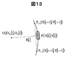
- FIG. 13 is a diagram showing coordinates, turning radius, and turning center.
- the Pi-1Pi + 1 component of the vector connecting the (i-1) th and (i + 1) th vehicle positions is expressed by the following equation (12).
- Equation 13 the component of the vector OiPi that connects the i-th turning center and the i-th vehicle position is expressed by Equation 13 below.
- Equation 16 the i-th turning center Oi (OX [i], OY [i]) is expressed by Equation 16 below.
- Equation 18 is an integration of the yaw rate r [j].
- ⁇ t 0.01 seconds.
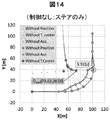
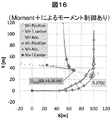
- ⁇ Evaluation results of turning center and combined acceleration> 14, 15, and 16 show the results of calculating the vehicle position, the turning center, and the terminal position of the resultant acceleration vector applied to the vehicle with respect to the space fixed coordinate system for the case of no control, GVC, and Moment + control using the equations in the previous section. From 2 seconds to 4 seconds to start cornering is plotted in 0.5 second increments, and otherwise it is plotted in 1 second increments. Connecting the end position of the resultant acceleration vector from the vehicle position results in the resultant acceleration vector (multiplied by 10 (arrow) for ease of viewing. The unit is [G]). Further, a dotted line is drawn from the vehicle position toward the instantaneous turning center at that time.
- Each round frame in the figure shows the vehicle position when the X coordinate of the instantaneous turning center is maximized, that is, when the turning center moves farthest from the approach direction, and the time at that time.
- FIG. 17 summarizes the time, turning center coordinates, and deviation of the target route from the turning center at this time.
- FIG. 18 shows the steering angle, longitudinal acceleration, and the like when lane change range is simulated by placing pylon A and pylon B at a distance of 30 m, passing through the right side of pylon A, and moving to the left side of pylon B.
- this compares the state in which only yaw moment control by ESC is operated and the state in which combined control of yaw moment control by GVC and ESC is operated.
- the ESC yaw moment control logic is not M + itself, but it is considered sufficient for comparative evaluation of deceleration control and moment control.
- GVC and ESC linkage control has a deceleration from the moment steering is started, and the speed is reduced by 10km / h in 0.5 seconds from the start of steering.
- the steering angle is small, and the roll rate and pitch rate are greatly reduced, and it can be seen that the lane change can be performed safely.
- the speed can be automatically reduced greatly for the same task, and the avoidance performance can be greatly improved.
- the longitudinal motion control and moment control linked to these lateral motions are characterized by the fact that they can be controlled from the normal region by operating from the normal region, but from a completely different viewpoint, High demands are often made on the NVH (Noise, Vibration, Harshness) performance or endurance performance of actuators to achieve smooth control.
- the operation rate of the longitudinal acceleration control (GVC) linked to the lateral motion is increased as compared with the case where the danger potential is small or zero.
- GVC longitudinal acceleration control
- M + greatly reducing the speed, maximizing the direction component opposite to the speed of the resultant force applied to the vehicle (the direction away from the obstacle)
- the operating rate of yaw moment control (M +) is increased, the deceleration is reduced compared to GVC, and the feeling is improved.
- the evaluation of the danger potential is a situation where the distance to the obstacle is still far away, that is, when the danger has not yet become apparent, and when the avoidance operation is actually performed by sudden braking or steering. It can be thought of as encountering.
- an external environment recognition sensor is required to grasp the environment other than the own vehicle, that is, the relative position, relative speed, relative acceleration with respect to obstacles on the course.
- FIG. 19 shows the overall configuration of the first embodiment of the vehicle using the vehicle motion control apparatus of the present invention that makes it possible to increase the ratio of the gain GVC to the amount (lateral jerk, side slip angle change, etc.).
- the present invention can be applied even if only the steering mechanism has mechanical coupling and the driver directly determines the steering angle.
- the vehicle 0 is a rear wheel drive vehicle (Rear Engine Rear Drive: RR vehicle) that drives the left front wheel 61 and the right front wheel 62 by the engine 1 (the drive system is not particularly related to the present invention).
- RR vehicle rear wheel drive vehicle
- the drive system is not particularly related to the present invention.
- the left front wheel 61, the right front wheel 62, the left rear wheel 63, and the right rear wheel 64 are equipped with a brake rotor, a wheel speed detection rotor, and a wheel speed pickup on the vehicle side so that the wheel speed of each wheel can be detected. It has become.
- the amount by which the driver's accelerator pedal 10 is depressed is detected by the accelerator position sensor 31 and is processed by an ADAS (Advanced driver assistance system) controller 40 via the pedal controller 48.
- the power train controller 46 controls a throttle, a fuel injection device, and the like (not shown) of the engine 1 according to this amount.
- the electronically controlled transmission may be a torque converter type automatic transmission, a wet multi-plate clutch type automatic transmission, a semi-automatic transmission, a continuously variable transmission (CVT), or a dual clutch transmission.
- ⁇ Deceleration can be applied by switching the gear ratio from the engine to each wheel based on the speed reduction (deceleration) command output from the ADAS controller 40.
- a deceleration action can be generated based on a longitudinal motion command “linked to lateral motion” such as a deceleration, a target speed command, etc. calculated from a road shape such as a curve or obtained later by GVC.
- Accelerator reaction force motor 51 is also connected to accelerator pedal 10, and the reaction force is controlled by pedal controller 48 based on the calculation command of ADAS controller 40. Further, a sudden accelerator-off is detected from the movement in the direction of closing the accelerator, particularly the speed in the direction of closing the accelerator, and “quantification of danger potential using driver accelerator operation” is performed.
- the steering system of the vehicle 0 is a front wheel steering device, but has a steer-by-wire structure in which there is no mechanical coupling between the steering angle of the driver and the tire turning angle.
- the power steering 7 includes a steering angle sensor (not shown), a steering 16, a driver steering angle sensor 33, and a steering controller 45.
- the steering amount of the steering wheel 16 of the driver is detected by the driver steering angle sensor 33 and is processed by the ADAS controller 40 via the steering controller 45.
- the steering controller 45 controls the power steering 7 in accordance with this amount.
- a steering reaction force motor 53 is also connected to the steering 16, and the reaction force is controlled by the steering controller 45 based on the calculation command of the ADAS controller 40.
- the ADAS controller 40 detects the sudden steering wheel from the steering operation amount of the driver, particularly the steering angular velocity, and performs “quantification of danger potential using the driver steering operation”.
- the operation amount (depression amount) of the brake pedal 11 of the driver is detected by the brake pedal position sensor 32 and is processed by the ADAS controller 40 via the pedal controller 48.
- the left front wheel 61, the right front wheel 62, the left rear wheel 63, and the right rear wheel 64 are each provided with a brake rotor, and a caliper that decelerates the wheel by sandwiching the brake rotor with a pad (not shown) on the vehicle body side. Is installed.
- the caliper is a hydraulic type or an electric type having an electric motor for each caliper.
- the hydraulic type instead of the conventional negative pressure booster, a simple method of generating the master cylinder hydraulic pressure using a hollow motor and its internal ball screw as an actuator is adopted, and regenerative braking by a driving motor for hybrid electric vehicles and electric vehicles Electric actuation that can secure the necessary braking force with natural pedal feeling may be used in cooperation with ITS, or it can be pressurized with an ITS compatible ESC (Electronic Stability Control) multi-cylinder plunger pump or gear pump Good.
- ITS compatible ESC Electronic Stability Control
- Each caliper is basically controlled by the brake controller 450 based on the calculation command of the ADAS controller 40. Further, as described above, vehicle information such as wheel speed, steering angle, yaw rate, longitudinal and lateral acceleration of each wheel is input to the brake controller 450 via the ADAS controller 40 or directly, and the vehicle speed V, the vehicle The skid angle is calculated. These pieces of information are constantly monitored as shared information in the ADAS controller 40.
- the brake pedal reaction force motor 52 is also connected to the brake pedal 11, and the reaction force is controlled by the pedal controller 48 based on the calculation command of the ADAS controller 40.
- the ADAS controller 40 detects a sudden brake from the brake pedal operation amount of the driver, particularly the pedal speed, and performs “quantification of danger potential using the driver brake pedal operation”.
- the lateral acceleration sensor 21 and the longitudinal acceleration sensor 22 are arranged near the center of gravity.
- Differentiating circuits 23 and 24 are provided which differentiate the outputs of the respective acceleration sensors to obtain jerk information.
- each sensor is installed in order to clarify the existence of the differentiation circuit.
- the acceleration signal is directly input to the ADAS controller 40 to perform various calculation processes, and then the differentiation process is performed. May be.
- lateral jerk may be obtained by using estimated yaw rate / lateral acceleration using a vehicle speed, a steering angle, and a vehicle motion model. They may be used in combination by such processing. Further, the estimation accuracy based on the vehicle motion model is improved by using the signal of the yaw rate sensor 38.
- the road surface condition (friction coefficient, etc.) is estimated, the road surface gradient, etc. are estimated, and "quantification of danger potential for the driving environment" is performed.
- the downhill with a large road gradient has a high danger potential and may improve the lateral motion linkage gain, but if the road friction coefficient is low, the danger potential is high but the lateral motion Increasing the linkage gain creates a risk of wheel lock. Therefore, in such a case, it is necessary to increase the gain and incorporate wheel overslip prevention control as disclosed in Japanese Patent No. 4920054.
- the vehicle 0 is equipped with an HVI (Human Vehicle Interface) 55 that transmits assist information (system operation information) to the driver.
- the HVI 55 communicates system operation information to the driver by a plurality of means in cooperation with a screen that can be seen by the driver, a warning sound, or reaction force control of each pedal.
- the vehicle 0 is equipped with a stereo camera 70 and a stereo image processing device 701.
- the stereo camera 70 is composed of a CCD camera that is two image sensors in the left-right direction.
- the two CCD cameras are arranged, for example, in such a manner as to sandwich a room mirror (not shown) in the vehicle interior, individually image the object in front of the vehicle from different coordinates of the vehicle fixed system, and stereo the two pieces of image information.
- the image is output to the image processing apparatus 701.
- a CCD camera is used here, a CMOS camera may be used.
- the stereo image processing device 701 receives image information from the stereo camera 70 and a vehicle speed V from the brake controller 450 via the ADAS controller 40. Based on these pieces of information, the stereo image processing device 701 recognizes forward information such as three-dimensional object data and white line data ahead of the vehicle 0 based on image information from the stereo camera 70, and estimates the own vehicle travel path.
- the stereo image processing device 701 checks the presence of a three-dimensional object such as an obstacle or a preceding vehicle on the road on which the vehicle will travel in the future, recognizes the closest three-dimensional object as an obstacle for preventing collision, Output to ADAS controller 40. Then, the ADAS controller 40 performs “quantification of danger potential using external information” based on the vehicle speed, relative position, relative speed, relative acceleration, and the like (referred to as travel environment data).
- FIG. 20 shows the internal configuration of the ADAS controller 40 and brake controller 450 of the present invention.
- the brake controller 450 has a port for ACC, a deceleration control input that enables pre-crash braking, and a yawing moment input for a lane departure prevention system.
- the vehicle deceleration and yawing moment can be controlled by inputting a control command to the brake controller 450 using an appropriate method based on the input / output information of the CAN (Control Area Network) I / O port.
- CAN Control Area Network
- the ESC control unit 451 also has a logic to perform arbitration operation (four-wheel braking force distribution) such as setting an upper limit value on the input port side command and temporarily disabling it. Built in.
- arbitration operation four-wheel braking force distribution
- the ADAS controller 40 takes in external information such as stereo camera, radar, GPS, etc. and vehicle information such as vehicle speed, steering angle, acceleration, yaw rate, etc., and estimates the risk, that is, in the input external information and vehicle information. Based on this, a danger potential estimation unit 41 for estimating the danger potential of the vehicle is provided. Further, an acceleration / deceleration controller 43 and a yawing moment controller 44 are provided. In this embodiment, the acceleration / deceleration controller 43, which is a vehicle longitudinal motion control unit, includes GVC logic. Based on Equation 1, “the longitudinal motion linked to the lateral motion” is obtained as the command value for the acceleration / deceleration.
- a vehicle longitudinal motion control command is generated based on the lateral jerk of the vehicle and a predetermined gain.
- the yawing moment controller 44 which is a vehicle yawing motion control unit, includes Moment ⁇ Plus logic, and based on Equation 2, “longitudinal motion linked to lateral motion” is obtained as a command value for the yawing moment.
- a yaw motion control command for the vehicle is generated on the basis of the lateral jerk and a predetermined gain.
- the ADAS controller 40 which is the vehicle motion control device of the present invention, is based on the input external world information and vehicle information, the risk potential estimation unit 41 for estimating the vehicle risk potential, the vehicle side jerk, The acceleration / deceleration controller 43 and the yawing moment controller 44 that generate the vehicle longitudinal motion control command based on the determined gain, and the vehicle longitudinal motion control command and the yawing moment controller 44 generated by the acceleration / deceleration controller 43 are generated.
- the ratio of the yawing motion control command of the vehicle is adjusted, that is, the ratio between the deceleration control and the moment control, and the ratio adjusting unit 42 for adjusting the ratio, and the ratio adjusting unit 42 is estimated by the risk potential estimating unit It is characterized by adjusting the ratio of deceleration control and moment control based on the danger potential.
- the ADAS controller 40 obtains the gains of these “longitudinal motions linked to the lateral motion” (the vehicle lateral jerk gain (first gain) Cxy in the acceleration / deceleration controller 43 and the equation 2 in the yaw moment controller 44). Are multiplied by the vehicle lateral jerk gain (second gain) Cmn) to determine respective command values for deceleration and moment. That is, the acceleration / deceleration controller 43, which is a vehicle longitudinal motion control unit, calculates a longitudinal acceleration command value of the vehicle based on the lateral jerk of the vehicle and a predetermined first gain (Cxy), and outputs the longitudinal acceleration command value.
- the acceleration / deceleration controller 43 which is a vehicle longitudinal motion control unit, calculates a longitudinal acceleration command value of the vehicle based on the lateral jerk of the vehicle and a predetermined first gain (Cxy), and outputs the longitudinal acceleration command value.
- the yawing moment controller 44 which is a vehicle yawing motion control unit, calculates the yaw moment command value of the vehicle based on the lateral jerk of the vehicle and a predetermined second gain (Cmn), and outputs the yaw moment command value.
- the ratio adjustment unit 42 sets the deceleration control ratio to the moment control ratio when the danger potential is higher than a predetermined value based on the danger potential estimated by the danger potential estimation unit 41 compared to when the danger potential is low. Adjust so that it is larger. Further, when the dangerous potential is detected by the dangerous potential estimation unit 41, the ratio of the vehicle longitudinal motion control command is larger than the ratio of the vehicle yawing motion control command, or the vehicle longitudinal Adjustment is made so that the motion control command becomes larger and the yawing motion control command of the vehicle becomes smaller.
- the ratio RGM of deceleration to yawment is calculated or referred to on the map (0 ⁇ RGM ⁇ 1, 0 is moment control only, 1 is deceleration control only).
- the deceleration command calculated by the acceleration / deceleration controller 43 is multiplied by RGM as a gain and sent to the deceleration port of the brake controller 450.
- (1-RGM) is multiplied as a gain to the moment command calculated by the yawing moment controller 44 and sent to the moment port of the brake controller 450.
- the ratio adjustment unit calculates the ratio of deceleration to yawment (RGM, 0 ⁇ RGM ⁇ 1) based on the risk potential estimated by the risk potential estimation unit 41, and adds the ratio (RGM) to the longitudinal acceleration command value.
- RGM deceleration to yawment
- the ratio adjustment unit 42 increases the ratio of deceleration to yam (RGM) when the risk potential estimated by the risk potential estimation unit 41 is higher than a predetermined value, compared to the case where the risk potential is lower than the predetermined value. Or if no danger potential is detected, adjust the deceleration to yaw ratio (RGM) to zero.
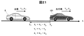
- the preceding vehicle 101 is traveling in front of the host vehicle 0 traveling in the x direction
- the position of the host vehicle 0 is xf
- the speed is vf
- the acceleration is af
- TTC Time-To-Collision
- TTC is an index that predicts the time until the vehicle collides with a preceding vehicle, assuming that the current relative speed is maintained.
- KdB is an index defined based on a hypothesis that "the driver is performing acceleration / deceleration operation while detecting approach / separation by a visual area change of the preceding vehicle".
- THW It is an index indicating the time to reach the current preceding vehicle position at the current host vehicle speed.
- TTC is an index that is equivalent to the time change of the rate of increase of the size of the preceding vehicle (visual with respect to the preceding vehicle) or the time change of the logarithm of the inter-vehicle distance.
- RF is an index that defines the linear sum of the reciprocal of TTC and THW as the risk that the driver feels subjectively for the purpose of expressing the vehicle speed control characteristics of the driver as a physical quantity when following the preceding vehicle (a, b is a weighting constant determined in advance).
- the 1 / TTC (reciprocal of Time-To-Collision) of Equation 19 is used, which shows an increasing tendency as the vehicle 0 approaches the preceding vehicle 101 or an obstacle (not shown). To do.
- FIG. 22 schematically shows the relationship between 1 / TTC, the relative distance Di between obstacles, and the collision risk potential.
- the danger potential may be quantified stepwise as indicated by a solid line in FIG. 22 or continuously as indicated by a dotted line in FIG. In this way, 1 / TTC enables quantitative evaluation of danger potential.
- FIG. 23 shows an example in which the quantitative evaluation of the danger potential using the driver steering operation is performed based on the steering angular velocity information output from the in-vehicle steering angle sensor.
- the steering speed is increased. Therefore, when the steering speed is slow, it can be regarded as normal driving, and when the steering speed is fast, it can be regarded as a high danger potential.
- the danger potential is symmetric with respect to the left and right steering angular velocities, but it may be left and right or non-target with respect to “right-hand traffic” and “left-hand traffic”, or counter steer (steering in a certain direction).
- the two-dimensional map of the steering angle and the steering angular velocity may be used in addition to the steering angular velocity.
- the quantification of the danger potential may be performed stepwise as indicated by a solid line in FIG. 22 or may be performed continuously as indicated by a dotted line in FIG.
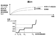
- FIG. 24 shows information on the deviation (D) between the standard motion of model estimation with respect to the steering angle and the actual motion actually measured by the sensor for quantitative evaluation of the risk potential using the lateral motion generated by the driver steering operation.
- D deviation
- a vehicle lateral motion model for example, a transfer function notation disclosed in JP 2010-076584 is well known. If this vehicle lateral motion model is used, yaw response, side slip angle, lateral acceleration, or lateral jerk can be calculated with respect to the steering angle input. The value calculated using the vehicle lateral movement model is adjusted so as to coincide with the actually measured value while the tire generating cornering force is linearly related to the tire side slip angle.
- the steering angle becomes large or the lateral acceleration increases, so that the linearity of the tire slip angle and the cornering force is lost.
- a large divergence occurs between the model estimation normative movement and the actual movement.
- the urgency is low, and it can be considered that the urgency increases as the divergence increases. Therefore, when the deviation (D) between the normative motion and the actual motion is small, it can be regarded as during normal operation, and when it is large, it can be regarded as when the danger potential is high.
- the danger potential may be quantified stepwise as shown by a solid line in FIG. 24 or continuously as shown by a dotted line in FIG.
- the danger potential is defined as "the danger potential is high when the angular speed is high" for the pedal angular speed on the accelerator-off side and the pedal angular speed on the brake depression side. An evaluation may be performed.
- FIG. 25 corresponds to the quantitative risk potentials of FIGS. 22, 23, and 24 with the qualitative risk level evaluation index
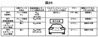
- FIG. 26 quantifies the risk potential in the embodiment of the present invention. It is the table
- RPO indicates a “no danger” situation, and this is almost the case under normal operating conditions (occurrence frequency is high).
- the ratio of deceleration control by GVC is reduced (0 to 0.25 in this example), and the moment control ratio by M + is increased (1.0 to 0.75). Discomfort can be reduced while maintaining the benefits of exercise control linked to exercise.
- the ratio at this time not only the ratio at this time but also the lateral movement linkage gains such as Cxy and Cm can be set to zero, so that the operating frequency of the deceleration actuator can be significantly reduced under normal conditions. Can be greatly eased.
- the probability of NVH performance becoming a problem can be greatly reduced for vehicles equipped with an inexpensive deceleration actuator with low NVH performance.
- the ratio of the deceleration control and the yaw moment control is changed based on the danger potential, but also the gain for determining each control command is changed using FIGS. It will be described in the second embodiment mentioned above.
- vibration control such as multi-information display, buzzer, steer reaction force and pedal reaction force of HVI55 is not performed.
- RP1 is a situation where there is a possibility of a collision, and if it continues in this state without acceleration / deceleration, it will collide. Therefore, it is necessary to urge the driver to brake (including engine brake) (at this stage, automatic brake control is not performed).
- a forward caution is displayed along with the vehicle ahead, and a buzzer “Pipipi...” is sounded to inform the driver of the possibility of a collision. Furthermore, a weak vibration is applied to the steering reaction force, pedal reaction force, etc., to call attention.
- the ratio of deceleration to yawment RGM is set larger than that for RP0 (0.2 ⁇ 0.4), and the ratio of deceleration control is increased to increase the avoidance potential for avoiding steering in the unlikely event of a collision. Improve (if steering is not achieved, it will not affect the vehicle motion).
- RP3 is in a situation where “the possibility of a collision is very high”, and a strong automatic brake (emergency brake) is applied. Furthermore, the ratio RGM of deceleration to yawment is made larger than RP2 (0.6 ⁇ 0.8 to 1.0). This makes it possible to reduce the rate at which the force in the deceleration direction is relaxed when creating a moment, and to obtain the maximum deceleration with four wheels, which is advantageous for emergency avoidance.
- the buzzer sound is a continuous sound called “Peep”, and the steering reaction force and pedal reaction force are larger than RP2.
- FIG. 27 is a diagram schematically showing these situations.
- the deceleration control GVC expressed by the above equation 1 and the moment control M + expressed by the equation 2 can be considered by omitting the sign function, first-order lag, etc.
- the moment command value is obtained by multiplying the vehicle lateral jerk by Cm, which is a lateral motion linkage gain. Further, in the ratio adjusting unit 42, the moment command value is multiplied by (1-RGM), and the deceleration command value is multiplied by RGM, which are sent to the moment port and the deceleration port of the brake controller 450, respectively.
- the ratio of deceleration to yawment RGM is set larger and adjusted to increase the ratio of deceleration control, avoidance after alarm, avoidance after alarm brake, emergency Avoid after braking.
- the ratio of deceleration to yament RGM may be changed to increase stepwise or to increase continuously as the quantified danger potential increases.
- FIG. 28 shows these control functions with the deceleration command value and moment command value per unit lateral drive (for example, lateral jerk 1 m / s3) as the vertical axis and the risk risk as the horizontal axis.
- the deceleration command value GmL for RPL and the deceleration command value GmS for RPs then GmL> GmS.
- MmL ⁇ MmS.
- FIG. 29 is a conceptual diagram more clearly showing the configuration of the vehicle motion control system of FIG.
- a relative distance, relative speed, and relative acceleration with an obstacle are detected by an external sensor such as a stereo camera, and the ADAS controller 40 uses this information to quantify the danger potential based on a criterion of 1 / TTC, for example.
- the RGM is added to the deceleration command calculated by the acceleration / deceleration controller 43 by the ratio adjustment unit 42 configured by a map etc. that stores the ratio RGM of deceleration to yawment according to the degree of danger. Is multiplied by (1-RGM) to the moment command calculated by the yawing moment controller 44, and each command value is transmitted to the brake controller 450 as a CAN signal or the like.
- the ratio adjustment unit 42 may be configured to output a gain corresponding to the estimated danger potential using a map in which a ratio of deceleration to yawment corresponding to the danger potential stored in advance is recorded.
- the deceleration command and the moment command are exclusively transmitted to the brake controller 450, but the ADAS controller 40 is not only applied to the brake controller 450 but also to the motor 1 for regenerative braking, the CVT 2, or the like. It is also possible to send a deceleration command and a moment command to realize a longitudinal motion control and a moment control linked to a suitable lateral motion based on the danger potential.
- the deceleration command and the moment command linked to the lateral motion are not issued, but the linear braking control based on the danger potential is of course performed.
- the system has improved the avoidance potential when an emergency avoidance steering operation is performed, the operation of the longitudinal motion control linked to the lateral motion is not performed automatically, the driver's intention (steering Note that this is the first time based on the operation.
- the accelerator in the case of a rear-wheel drive vehicle, in combination with the steering operation, the accelerator may be fully opened, the rear wheel lateral force may be reduced by the driving force, the yawing motion may be suddenly started to avoid the parking brake, It may be operated to lock the rear wheel and avoid it in a so-called spin turn state.
- a preset threshold value is set for the amount of operation of the accelerator or parking brake. When this threshold value is exceeded, the lateral motion linkage gain of “Deceleration linked to lateral motion, moment command” is set. The gain is set to be smaller than the gain determined according to the danger potential.
- the longitudinal motion control command linked to the lateral motion becomes zero when the accelerator operation command from the driver is input exceeding a predetermined threshold.
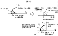
- FIG. 30 is a diagram showing a linkage state between linear deceleration by automatic braking such as “alarm braking” and “emergency braking” and deceleration control and moment control linked to lateral motion by GVC and M +.
- the figure on the left shows a “gg” diagram showing how the vehicle's resultant acceleration vector G (Gx, Gy) changes with the vehicle longitudinal acceleration on the x-axis and the vehicle lateral acceleration on the y-axis. .
- each automatic brake control configured with reference to Patent Document 1 and shown in FIGS. 26 and 27 is linear deceleration in which only the longitudinal motion is controlled.
- FIG. 30 shows the transition of the combined acceleration vector G (Gx, Gy) of the deceleration and lateral acceleration in GVC and M + during the avoidance operation by the steering without considering this linear deceleration. It is a curve. The starting point is from the origin.When avoiding to the left, a positive lateral acceleration and a longitudinal deceleration are added in conjunction with this, so when the lateral acceleration increases and moves to another lane, Changes in four quadrants.
- automatic brake control such as alarm brake or emergency brake sets a time during which braking control is prohibited when the steering angle or the steering angular velocity by the driver increases.
- the automatic brake control is released.
- deceleration control and moment control linked to lateral motion are performed by GVC and M +. May occur.
- G loss brake loss
- a smoothing means such as a first-order lag filter (low-pass filter) is used in the ADAS controller 40 so that the linear deceleration command by the automatic brake does not drop suddenly (stepwise) at the steering start timing.
- GVC linked to the lateral movement generated by the steering operation and the deceleration by M + are smoothly connected, and as shown in FIG. It is possible to transition to only point C.
- a gain K which is multiplied by the deceleration command value calculated by the acceleration / deceleration controller 43 and the moment command value calculated by the yawing moment controller 44,
- it has a gain adjustment unit that stores it in the maps 460, 461 and the like.
- the maps 460 and 461 store a relationship in which the gain K increases as the danger potential increases, as with the deceleration to yawment ratio RGM in FIG.
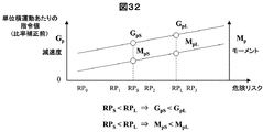
- Fig. 32 shows the deceleration command value and moment command value (before ratio correction) per unit lateral motion rod (for example, lateral jerk 1m / s3) by two vertical axes.
- the risk risk is RPS ⁇ RPL
- GpL for ⁇ ⁇ RPL and the deceleration command value GpS for RPs then GpL> GpS.
- the moment command value MpL for RPL and the deceleration command value MpS for RPs the relationship is MpL> MpS.
- the ratio adjustment unit 42 multiplies the deceleration command value Gp by the RGM among the control command values (Gp, Mp) multiplied by the gain K by the brake force distribution adjustment means 452 and 453 in the gain adjustment unit, and obtains the moment command value. Multiply Mp by (1-RGM) and send each command value to the brake controller 450 as a CAN signal or the like.
- both the deceleration by the deceleration control and the resulting deceleration by the moment command can be fundamentally reduced to improve the feeling.
- the use frequency of the actuator as described below can be reduced.
- the lateral movement linkage gain is set to “zero” when the danger potential is RP0, that is, no danger as shown in FIGS.
- the deceleration command and moment command are both zero, and the deceleration actuator does not operate.
- the second embodiment of the present invention when the second embodiment of the present invention is not adopted and the same gain (normalized gain 1.0) is set from the “no danger” state (RP0) to the “highly possible collision” state (RP3).
- the gain for RP0 is 0.0 as the risk level increases as shown below.
- Gain for RP1 1.0
- Gain for RP2 1.5
- Gain for RP3 2.0 By adopting the control method of the present invention that increases the gain, the lifetime normalized operating time (including the operating strength) can be reduced to 2.3%.
- the present invention improves emergency avoidance performance I can do it.
- the present invention it is possible to provide a vehicle motion control device that reliably assists the driver during emergency avoidance steering without being jerky during normal times.
- the gain in the “normal area”, which has a very high occurrence frequency, to zero the possibility of adopting braking actuators with low durability and low NVH performance has been expanded, and the above-mentioned advantages have been enjoyed even for low-cost range vehicles. You can provide that you can.
- yaw moment ratio adjustment unit 43 Acceleration / deceleration controller 44 Yawing moment controller 450 Brake controller 451 ESC control unit 452 Brake force distribution adjustment means 45 Steering controller 46 Powertrain controller 48 Pedal controller 51 Accelerator Reaction force motor 52 Brake pedal reaction force motor 53 Stair reaction Motor 61 left front wheel 62 right front wheel 63 left rear wheel 64 Right rear wheel 70 stereo camera 701 stereo image processing apparatus
Landscapes
- Engineering & Computer Science (AREA)
- Transportation (AREA)
- Mechanical Engineering (AREA)
- Automation & Control Theory (AREA)
- Chemical & Material Sciences (AREA)
- Combustion & Propulsion (AREA)
- Regulating Braking Force (AREA)
- Control Of Driving Devices And Active Controlling Of Vehicle (AREA)
- Steering Control In Accordance With Driving Conditions (AREA)
Abstract
通常時にはぎくしゃくせず、緊急回避操舵時には確実にドライバをアシストする車両の運動制御装置を提供する。 入力された外界情報及び車両情報に基づいて、車両の危険ポテンシャルを推定する危険ポテンシャル推定部と、車両の横加加速度と予め定めたゲインとに基づいて車両の前後運動制御指令を生成する車両前後運動制御部と、車両の横加加速度と予め定めたゲインとに基づいて車両のヨーイング運動制御指令を生成する車両ヨーイング運動制御部と、車両の前後運動制御指令と車両のヨーイング運動制御指令の比率を調整する比率調整部と、を有し、比率調整部は、危険ポテンシャル推定部で推定された危険ポテンシャルに基づいて比率が調整される。
Description
本発明は、車両の前後加速度とヨーイングモーメントを制御する車両の運動制御装置に関する。
近年、自車両が先行車等の制御対象に衝突する可能性が高いときに、ドライバのブレーキ操作とは独立した自動ブレーキ制御を行うことで、衝突防止を図る様々な自動ブレーキ制御装置が提案され、実用化されている。例えば、特許文献1では、カメラで撮像した前方の道路環境に基づいて自車両前方の制御対象を認識し、自車両と制御対象との相対関係に基づいてブレーキ介入距離を設定し、自車両と制御対象との相対距離がブレーキ介入距離以下であるとき、制動制御の実行を判定し、自動ブレーキの介入による自動制動制御装置の技術が開示されている。
また、特許文献2には、入力された車両の横方向の加加速度(Gy_dot)に、速度(V)及び横加速度(Gy)から決定され、予め記憶されたゲイン(KGyV)を乗じ、乗じた値に基づいて、車両の前後加速度を制御する制御指令を生成し、生成された前記制御指令を出力することを特徴とする車両の運動制御方法が開示されている。この方法によると前後加速度と横加速度の合成加速度ベクトル(G)の軌跡が車両重心固定の座標系において、なめらかな曲線を描くように方向づけられ(Vectoring)、G-Vectoring制御(GVC:G-Vectoring Control)と呼ばれている。GVCによると、緊急回避性能が大幅に向上することが報告されている(非特許文献1)。
また、これに加え特許文献2には、車両の前後方向の速度(V)を検出する手段と、車両の横方向の加加速度(Gy_dot)を研修する手段を有し、加加速度を速度で除した値に基づいて車両のヨーモーメントを制御することを特徴とする車両の運動制御装置が開示されている。この方法は、車両の横滑り情報などに基づいてヨーモーメントを制御し、車両のヨー運動と規範モデルのヨー運動予測との誤差が小さくなるように制御するようなモデル追従のフィードバック制御ではない。操舵による発生する旋回促進ヨーモーメントや、車両がもともと持っている復元ヨーモーメントに対し、若干のアシストモーメンをくわえるということでMoment+(M+)と呼ばれている(非特許文献2)。このヨーモーメント制御には例えば特許文献3に示されるような、電動の車軸間トルク発生装置(ヨーモーメントジェネレータ)を用いてもよい。
M+制御を用いるとGVCに比べて少ない加減速度で車両の回頭性を向上することができる。たとえば特許文献3の電動式のヨーモーメントジェネレータを用いると、車軸間にトルク差、いわゆる対抗トルクを発生することができ、車両にヨーモーメントを直接加えることができるとともに、車両に加減速を生じさせることもない。また、昨今搭載が義務付けられている横滑り防止装置(Electronic Stability Control:ESC)を用いて、左右輪に異なる減速力を与えて、車両にヨーモーメントを加える場合においては、減速度が発生する。
しかしながら、GVCに比べて小さく、またGVCと同様なプロファイル(略車両横加加速度比例)で、前後と横の加速度が連係して変化するため、ESC介入のような唐突な減速なく、車両の回答性をあげることができる。
Yamakado, M., Takahashi, J., Saito, S.,: "Comparison and combination of Direct-Yaw-moment Control and G-Vectoring Control", Vehicle System Dynamics, Vol.48, Supplement, pp.231-254, 2012
Yamakado, M., Takahashi, J., Nagatsuka, K.,: "Triple hybrid control of ESC, Moment+ and G-Vectoring", Proc. of Chassis Tech plus 2013, 2013
特許文献1では制動制御ユニットがドライバによる操舵角|δ|が予め設定された閾値δ0以上であるか否かを調べ、操舵角|δ|≧δ0であると判定した場合、拡大制動制御の禁止時間を規定する禁止タイマtδをセットする。
また、制動制御ユニットは、ドライバによる操舵角速度|δ’|(=|dδ/dt|)が予め設定された閾値δ’0以上であるか否かを調べ、操舵角速度|δ’|≧δ’0であると判定した場合、制動制御ユニットは、拡大制動制御の禁止時間を規定する禁止タイマtδ’をセットする。
以上のように、特許文献1ではドライバによる操舵角、あるいは操舵角速度が大きくなると、制動制御を禁止する時間が設定される。すなわちドライバによる緊急回避操舵操作(一般的に操舵角、操舵角速度が大きい)が入った場合、この回避操作をアシストするものではない。
以上のように、特許文献1ではドライバによる操舵角、あるいは操舵角速度が大きくなると、制動制御を禁止する時間が設定される。すなわちドライバによる緊急回避操舵操作(一般的に操舵角、操舵角速度が大きい)が入った場合、この回避操作をアシストするものではない。
また、特許文献2のGVCにおいては、車両の前後加速度の制御指令値、特に減速度指令を構築するうえで、横方向の加加速度(Gy_dot)に乗じるゲイン(KGyV)を増加させると、基本的に減速度が増加し、制御稼働時の速度が大幅に低減できるため、操舵による回避性能は大幅に向上する。しかしながら、通常時の微小な操舵に対しても過敏に反応するために、ドライバにぎくしゃく感(違和感)を生じさせるという課題があった。
さらに、過敏に反応するということは、例えば制御稼働時のアクチュエータ要件(応答性、耐久性、NVH性能など)を厳しくしてしまい、コストアップを招きGVC技術の適用車種範囲を狭めることになってしまう。
一方、特許文献2のM+においては、旋回初期の回頭性は向上するものの、衝突回避などの緊急時には、減速度が少ないために、回避前の速度方向の成分を十分に落としきれず、回頭はするものの、速度方向に進みながら、自転する状況となりやすい。また、旋回促進モーメントを発生するために、後の内側輪に制動を加えることになるが、そもそも旋回のための横加速度で内輪から外輪への荷重移動が発生して荷重抜けを起こし、十分な制御効果を得られなくなる恐れがある。
本発明は、通常時には、ぎくしゃくせず、緊急回避操舵時には確実にドライバをアシストする車両の運動制御装置を提供することを目的とする。
上記目的を達成させるために、本発明の車両の運動制御装置は、入力された外界情報及び車両情報に基づいて、車両の危険ポテンシャルを推定する危険ポテンシャル推定部と、車両の横加加速度と予め定めたゲインとに基づいて車両の前後運動制御指令を生成する車両前後運動制御部と、車両の横加加速度と予め定めたゲインとに基づいて車両のヨーイング運動制御指令を生成する車両ヨーイング運動制御部と、車両の前後運動制御指令と車両のヨーイング運動制御指令の比率を調整する比率調整部と、を有し、比率調整部は、危険ポテンシャル推定部で推定された危険ポテンシャルに基づいて比率が調整される構成とする。
通常時には、ぎくしゃくせず、緊急回避操舵時には確実にドライバをアシストする車両の運動制御装置を提供することができる。
まず、課題を解決するための手段について、その基本的な考え方を説明し、その構成、実施形態について述べていく。
本発明の緊急回避時の運動性能向上面での効果を端的に述べると、以下のようになる。
少なくとも、車両の横運動に連係して前後加減速度を制御するモードと車両の横運動に連係してヨーモーメントを制御するモードを有し、外界情報あるいは車載情報に基づき、危険ポテンシャルを定量的に評価する手段を有し、危険ポテンシャルが大きくなった場合、危険ポテンシャルが小さい、あるいはゼロの場合に比べ、横運動に連係した前後加速度制御(ここでは減速)の稼働割合を大きくするとともに、ヨーモーメント制御の稼働割合を小さくし、速度を大きく低減するとともに、車両に加わる合力の速度と反対の方向成分(障害物から遠ざかる方向)を最大化することにより、緊急回避性能を向上するものである。
まず、横運動に連係した前後加速度制御とヨーイング制御について概要を述べ、緊急回避性能向上に対して支配的要因となる回避初期の車両挙動に前後加速度制御とヨーモーメント制御が及ぼす影響について述べ、両者の的確な稼働割合を明確にする。
<横運動に連係した前後加速度制御(G-Vectoring)>
ハンドル操作による横運動に連係して自動的に加減速することにより、前輪と後輪の間に荷重移動を発生させて車両の操縦性と安定性の向上を図る方法が、非特許文献1に示されている。具体的な加減速指令値(目標前後加速度Gxc)は、以下数1に示す通り、
<横運動に連係した前後加速度制御(G-Vectoring)>
ハンドル操作による横運動に連係して自動的に加減速することにより、前輪と後輪の間に荷重移動を発生させて車両の操縦性と安定性の向上を図る方法が、非特許文献1に示されている。具体的な加減速指令値(目標前後加速度Gxc)は、以下数1に示す通り、

基本的に横加加速度Gy_dotにゲインCxyを掛け、一次遅れを付与した値を前後加減速指令にするというシンプルな制御則である。
なお、Gyは車両横加速度、Gy_dotは車両横加加速度、Cxyはゲイン、Tは一次遅れ時定数、sはラプラス演算子、Gx_DCは横運動に連係しない加減速度指令とする。
これによりエキスパートドライバの横と前後運動の連係制御ストラテジの一部が模擬でき、車両の操縦性・安定性の向上が実現できることが、非特許文献1で確認されている。
この式のGx_DCは横運動に連係していない減速度成分(オフセット)である。前方にコーナーがある場合の予見的な減速、あるいは区間速度指令がある場合に必要となる項である。また、sgn(シグナム)項は、右コーナー、左コーナーの両方に対して上記の動作が得られるように設けた項である。具体的には、操舵開始のターンイン時に減速し、定常旋回になると(横加加速度がゼロとなるので)減速を停止し、操舵戻し開始時のコーナー脱出時に加速する動作が実現できる。
このように制御されると、前後加速度と横加速度の合成加速度(Gと表記)が、横軸に車両の前後加速度、縦軸に車両の横加速度をとるダイアグラムで、時間の経過とともに曲線的な遷移をするように方向付けられる(Vectoring)のため、「G-Vectoring制御」と呼ばれている。
数1の制御を適用した場合の車両運動に関して、具体的な走行を想定して説明する。
図1は、直進路A、過渡区間B、定常旋回区間C、過渡区間D、直進区間Eという、コーナーへの進入、脱出の一般的な走行シーンを想定している。このとき、ドライバによる加減速操作は行わないものとする。
また、図2は、操舵角、横加速度、横加加速度、数1にて計算した加減速指令、そして四輪の制動、駆動力について時刻暦波形として示した図である。後で詳細に説明するが、前外輪と前内輪、後外輪と後内輪は、左右(内外)それぞれ同じ値と成るように制動力・駆動力が配分されている。ここで制駆動力とは各輪の車両前後方向に発生する力の総称で、制動力は車両を減速する向きの力であり、駆動力は車両を加速する向きの力と定義する。
まず直進路区間Aから車両がコーナーに進入する。過渡区間B(点1~点3)では、ドライバが徐々に操舵を切増すに従い、車両の横加速度Gyが増加していく。横加加速度Gy_dotは、点2近辺の横加速度が増加している間、正の値をとることになる(横加速度増加が終了する3の時点ではゼロに戻る)。このとき、数1より、制御車両には横加速度Gyの増加に伴い、減速(Gxcは負)指令が発生する。これに伴い、前外、前内、後外、後内の各輪に略同じ大きさの制動力(マイナス符号)が加わることになる。
まず直進路区間Aから車両がコーナーに進入する。過渡区間B(点1~点3)では、ドライバが徐々に操舵を切増すに従い、車両の横加速度Gyが増加していく。横加加速度Gy_dotは、点2近辺の横加速度が増加している間、正の値をとることになる(横加速度増加が終了する3の時点ではゼロに戻る)。このとき、数1より、制御車両には横加速度Gyの増加に伴い、減速(Gxcは負)指令が発生する。これに伴い、前外、前内、後外、後内の各輪に略同じ大きさの制動力(マイナス符号)が加わることになる。
その後、車両が定常旋回区間C(点3~点5)に入ると、ドライバは操舵の切増しを止め、操舵角を一定に保つ。このとき、横加加速度Gy_dotは0となるため、加減速指令Gxcは0となる。よって、各輪の制動力・駆動力もゼロとなる。
次に、過渡区間D(点5~7)では、ドライバの操舵の切戻し操作によって車両の横加速度Gyが減少していく。このとき車両の横加加速度Gy_dotは負であり、数1より制御車両には加速指令Gxcが発生する。これに伴い、前外、前内、後外、後内の各輪に略同じ大きさの駆動力(プラス符号)が加わることになる。
また直進区間Eでは横加加速度Gyが0となり横加加速度Gy_dotもゼロとなるため加減速制御は行われない。以上のように、操舵開始のターンイン時(点1)からクリッピングポイント(点3)にかけて減速し、定常円旋回中(点3~点5)には減速を止め、操舵切戻し開始時(点5)からコーナー脱出時(点7)には加速する。このように、車両にG-Vectoring制御を適用すれば、ドライバは旋回のための操舵をするだけで、横運動に連係した加減速運動を実現することが可能となる。
また、この運動を前後加速度を横軸、横加速度を縦軸にとり、車両に発生している加速度様態を示す“g-g”ダイアグラムに表すと、滑らかな曲線状(円を描くよう)に遷移する特徴的な運動になる。本発明の加減速指令は、このダイアグラムで、時間の経過とともに曲線的な遷移をするように生成される。この曲線状の遷移は左コーナーについては、図1に示すように時計回りの遷移となり、右コーナーについては、Gx軸について反転した遷移経路となり、その遷移方向は半時計回りとなる。このように遷移すると前後加速度により車両に発生するピッチング運動と、横加速度により発生するロール運動が好適に連係し、ロールレイト、ピッチレイトのピーク値が低減される。
この制御は、図1に示すとおり、一次遅れ項、左右の運動に対する符号関数を省略して考えると、車両横加加速度にゲイン-Cxyを掛け合わせた値を前後加速度指令にしているので、ゲインを大きくすることにより、同一横加加速度に対して、減速度、あるいは加速度を大きくすることが出来る。
図3は、図1、2と同一のシチュエーションで通常ゲインの走行と、ゲインを高くした高ゲインの状態での旋回状況を示す図である。ゲインを大きくすることにより旋回開始時の減速度が大きくなり、通常ゲイン時に比べ、車両速度が低下し、同一操舵に対しても横加速度が小さくなり旋回時の安全性の向上につながる通常ゲインと強ゲインとの“g-g”ダイアグラムを比較すると、図3下のようになる。ダイアグラムの曲線は維持されるが、Gx方向に膨れた形になり、Gy方向は速度低下の影響を受け、若干すぼまる傾向となる。
一方、常に高ゲインにしておくと、微小な修正操舵に対しても大きな加減速が生じるようになり、ドライバおよびパッセンジャは強い減速感およびピッチング運動を感じるようになる。したがって、通常、GVCのゲインCxyは制御効果とフィーリングがバランスする0.25近辺に調整されている。しかしながら、緊急レーンチェンジなどにおいては、ゲインを向上したほうが、回避性能が大幅に改善することが確認されている。
<横運動に連係したヨーモーメント制御(モーメント・プラス(M+))(図4)>
モーメント・プラスはG-Vectoring Control(GVC)指令値を基に、即ち横加加速度情報を用いて、車両にヨーモーメントを加え、車両の操縦性と安定性を向上する、非特許文献2内で報告されている新たな制御則である。基本制御則は以下数2のように定式化される。
<横運動に連係したヨーモーメント制御(モーメント・プラス(M+))(図4)>
モーメント・プラスはG-Vectoring Control(GVC)指令値を基に、即ち横加加速度情報を用いて、車両にヨーモーメントを加え、車両の操縦性と安定性を向上する、非特許文献2内で報告されている新たな制御則である。基本制御則は以下数2のように定式化される。

この制御は、数2に示すとおり、一次遅れ項、左右の運動に対する符号関数を省略して考えると、GVCと同様に車両横加加速度にゲインCmnを掛け合わせた値をモーメント指令にしている。
また、一般的に車両の運動の安定性は速度の増加に伴い低下してくる。したがって、旋回促進モーメントに限っては速度増加に伴って、小さくするほうが、車両の安定性確保には有効である(非特許文献3:山門誠、長塚敬一郎:車両横加加速度に基づくヨーモーメント制御手法の検討(2)、自動車技術会学術講演会前刷集:60-13頁:21-26、2013参照)。
したがって以下数3のように、制御モーメントを速度に逆比例して加えるという方法も、特にオーバーステア気味の車両には有効であると考えられる。

もちろん、速度が低くなってくるとモーメント指令値は非常に大きくなるため、制御を停止する速度下限リミッターを持たせたり、極低速度では、制御量を固定したりする方法を取ってもよい。
M+制御では、直接的にヨーイング運動制御を制御するため、旋回するのではなく、自転するような感覚(いわゆる遊園地のティーカップフィーリング)が生じる場合がある。しかしながらESCによるブレーキ制御でM+制御を実現する場合、同一のヨー応答を得るには、GVCに比べて少ない減速度で実現可能となる。さらにその時の減速度も結果的に横加加速度に略比例したものとなり、GVCを低ゲインで実施しているのと同じ減速度(合成加速度がベクタリングする)となり、乗り心地の向上が期待できる。
このため、前述の感覚が強くならない範囲では、GVCを停止してM+制御のみにするか、あるいはGVCに対して、M+制御の割合を増やすように制御することにより、ヨー応答を向上しながら、ドライバおよびパッセンジャが感知する過度な減速感およびピッチング運動を低減することが可能となる。
<緊急回避時の減速度制御とヨーモーメント制御の割合配分指針(質点での計算)>
さて、GVCは専ら前後加減速度を制御するためのものでM+制御はヨーイング運動を制御するものであるため、これらの制御は非干渉で組み合わせることが出来る。したがって、前述のGVCとM+制御のどちらをメインの制御にするかは任意に決定できるということである。M+制御のところで記載したように、すくなくとも通常領域においては、(フィーリング上)M+制御の割合が大きいほうが好適なようである。
<緊急回避時の減速度制御とヨーモーメント制御の割合配分指針(質点での計算)>
さて、GVCは専ら前後加減速度を制御するためのものでM+制御はヨーイング運動を制御するものであるため、これらの制御は非干渉で組み合わせることが出来る。したがって、前述のGVCとM+制御のどちらをメインの制御にするかは任意に決定できるということである。M+制御のところで記載したように、すくなくとも通常領域においては、(フィーリング上)M+制御の割合が大きいほうが好適なようである。
ここでは、緊急回避性能向上に対して支配的要因となる回避初期の車両挙動に前後加速度制御とヨーモーメント制御が及ぼす影響について述べ、GVCとM+制御をどのように割合配分するかの指針について述べていくことにする。このためには、まず、旋回開始時の車両を質点とみなし(ヨーイング運動はひとまず考えない)、減速による影響を解析的に見ていくことにする。そして、つぎにヨー自由度も考慮した、フルビークルシミュレーションによる数値計算にて、GVCとM+制御の割合配分指針について述べる。
なお、障害物回避後の切り返し操舵、それに伴う安定性確保については、ESCがその役割を担うものとし、ここでは最も重要な、最初に障害物を避ける部分に特化して考えることにする。
<純粋な横力が作用する質点の運動>
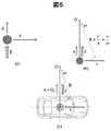
質量mの質点が速度vで運動していると仮定する(図5(a))。この質点に、速度方向に直角の外力Fが作用するとき、加速度aが発生し、F=maの関係が成り立つ。
この運動を瞬間的な運動と考えると、一定速度vで旋回運動(円運動)する質点に向心力Fが作用する状態と等価である(図5(b))。また、これと車両との関係を図5(c)に参考として示す(a=Gy)。速度方向と直角の方向に作用する外力Fを向心力、旋回中心方向に発生する加速度Gyを向心加速度と考えることができる。旋回運動における回転角速度をωとすると、向心加速度Gyは、vωであり、以下数4の関係が知られている。
<純粋な横力が作用する質点の運動>
質量mの質点が速度vで運動していると仮定する(図5(a))。この質点に、速度方向に直角の外力Fが作用するとき、加速度aが発生し、F=maの関係が成り立つ。
この運動を瞬間的な運動と考えると、一定速度vで旋回運動(円運動)する質点に向心力Fが作用する状態と等価である(図5(b))。また、これと車両との関係を図5(c)に参考として示す(a=Gy)。速度方向と直角の方向に作用する外力Fを向心力、旋回中心方向に発生する加速度Gyを向心加速度と考えることができる。旋回運動における回転角速度をωとすると、向心加速度Gyは、vωであり、以下数4の関係が知られている。

このように、等速度で進行する車両に横力が作用する瞬間的な運動は旋回運動として扱うことができ、横加速度Gyは、旋回半径Rや旋回角速度ωで表現することができる。
図6は、上記のような運動状態でΔt後までの軌跡を基準座標を空間に固定する固定座標系で示した図である。質点は座標原点P(0、0)からX方向へ速度vにて、X軸と平行に進入している。質点の旋回中心は、Y軸上の点O(0、R)となる。Δt後に質点は、Q(Rsin ω・Δt、 R(1-cos ω・Δt))へと移動することになる。この軌跡と、先行車(障害物)が干渉しなければ回避成功となる。
<速度方向成分を持つ横力が作用する質点の運動(GVC)>
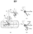
GVCは、横運動に連係した加減速制御であるため、前節で述べた速度方向と直角な外力成分Fyに加え、速度と同じ方向の減速度Gx、減速力Fxが作用することになる(図7(a))。
結果として外力の合成ベクトルFGVCの大きさは、以下数5となる。
<速度方向成分を持つ横力が作用する質点の運動(GVC)>
GVCは、横運動に連係した加減速制御であるため、前節で述べた速度方向と直角な外力成分Fyに加え、速度と同じ方向の減速度Gx、減速力Fxが作用することになる(図7(a))。
結果として外力の合成ベクトルFGVCの大きさは、以下数5となる。

cosγ<1なので、合成ベクトルは、速度方向と直角な外力成分よりも大きくなっていることに注意を要する。
さて、このような速度と外力の状態を図5(a)と同様に示すと、図7(b)の上側のような図となる。この速度を、図7(b)の下側のように、それぞれ合力FGVC(合成加速度aGVC)に直角の方向の成分v cosγと、平行な成分v sinγに分解して考える。まず、v cosγにのみ注目すると、この状態は速度v cosγで運動する質量mの質点に、速度方向に直角の外力FGVCが作用するとき、加速度aGVCが発生し、FGVC=m・aGVCの関係が成り立っていると見ることができる。
速度方向(v cosγ)と直角の方向に作用する外力FGVCを向心力、旋回中心方向に発生する加速度aGVCを向心加速度と考えることができる。旋回運動における回転角速度をωGVCとすると、向心加速度aGVCは、v cosγ・ωGVCであり、以下数6、7の関係となる。


また、図4と同様に、Δt後までの軌跡を考えるため、回転角速度ωGVCを求めると、以下数8となる。

結局、合力FGVC(合成加速度aGVC)に直角な方向の速度成分v cosγのみを考えると、質点は、初期位置からみて、速度成分に対して後ろにある点OGVCを旋回中心として、制御なしよりも小さな旋回半径RGVCで、同じ時間に対して回転角速度ωGVCも大きな状態で原点Pから(A)点に移動することがわかる。(A)点の座標を求めると、A(Rcos3γ・sin{γ+(ω/cos2γ)・Δt}-R cos3γ・sin γ、 Rcos3γ[cosγ-cos{γ+(ω/cos2γ)・Δt}])となる。
つぎに、合力FGVC(合成加速度aGVC)に平行な成分v sinγを考えると、質点は旋回中心OGVCと(A)点を結ぶ直線の延長上に、v sinγ・Δt進んだ点(B)に移動することがわかる。したがって点Bの座標はA(Rcos3γ・sin{γ+(ω/cos2γ)・Δt}-R cos3γ・sin γ+v sinγ・cos(γ+(ω/cos2γ)・Δt-π/2)、 Rcos3γ[cosγ-cos{γ+(ω/cos2γ)・Δt}] + v sinγ・sin(γ+(ω/cos2γ)・Δt-π/2))となる。この軌跡と、先行車(障害物)が干渉しなければ回避成功となる。
図9に示すように、速度vで原点を通過する質点に対し、速度方向と直角の成分のみを持つ外力に加え(制御なし)、速度方向と平行な成分を加えた外力FGVCが加わると(制御あり)、少なくとも旋回初期では質点の軌跡は内側を通るということがわかった。この軌跡と、先行車(障害物)が干渉しなければ回避成功となる。図より、明らかにGVC (減速制御)を行った方が、減速制御を行わない、すなわちステアのみの回避の場合に比べて障害物を効果的に避けられることが分かる。
また制御ありは、制御なしに比べて作用する力の絶対値が大きくなることに留意されたい。これはタイヤ横力だけではなく、前後力をも用いて遠心力に対抗する向心力としていることと等価である。すなわち、転がり抵抗が少なく幅が細いタイヤであっても、前後力を効果的に用いることにより、旋回力を賄うことができることを示している。
これまでの検討は、質点の運動に関するものであり、もちろん車両のヨーイング運動などは考慮できない。逆に考えると加減速度を伴わない電動ヨーモーメント制御装置などを用いる場合には、本章で述べたメカニズムでは、軌跡の内側化、すなわち緊急回避のときの初期回避性能向上効果は得られないことになる。これはあくまでも質点の運動のみを考えたケースであるため、つぎにフルビークルモデル(ヨー、ロール、ピッチなどの回転運動も考慮可能)を用いた解析で、さらに詳しく精査する。
<緊急回避時の減速度制御とヨーモーメント制御の割合配分指針(シミュレーションによる検証)>
前章で述べた質点の運動についてフルビークルモデルを用いた車両運動シミュレーション(簡略化のためLターンを想定)に拡張し、特に旋回時の減速制御を行った際の、旋回中心の移動という観点から精査した。もちろん旋回中心が障害物から遠い、手前のほうにあるほうが、緊急回避性能及び、ドライバに対する安心感も高くなると思われる。
<シミュレーション条件>
シミュレーション条件を表1に示す。路面はドライアスファルトを想定し、進入速度は80km/hと、半径40mのLターンとしている(図10)。タイヤモデルとしては非線形コンバインドタイヤ力を考慮することができるマジックフォーミュラモデルを用いている。また、ドライバモデルは、一般的な2次予測前方注視モデルを用いて計算している。前方に障害物があるときに、半径40mのL字状の軌跡を想定し回避動作を行っている状態を模擬している。
<緊急回避時の減速度制御とヨーモーメント制御の割合配分指針(シミュレーションによる検証)>
前章で述べた質点の運動についてフルビークルモデルを用いた車両運動シミュレーション(簡略化のためLターンを想定)に拡張し、特に旋回時の減速制御を行った際の、旋回中心の移動という観点から精査した。もちろん旋回中心が障害物から遠い、手前のほうにあるほうが、緊急回避性能及び、ドライバに対する安心感も高くなると思われる。
<シミュレーション条件>
シミュレーション条件を表1に示す。路面はドライアスファルトを想定し、進入速度は80km/hと、半径40mのLターンとしている(図10)。タイヤモデルとしては非線形コンバインドタイヤ力を考慮することができるマジックフォーミュラモデルを用いている。また、ドライバモデルは、一般的な2次予測前方注視モデルを用いて計算している。前方に障害物があるときに、半径40mのL字状の軌跡を想定し回避動作を行っている状態を模擬している。
制御ケースとしては図11に示すように、(i)制御なしは、ブレーキによる制動力を加えず、操舵のみでLターンをクリアするケース、(ii)はGVCによる減速度を与えるケース、(iii)は、GVCの指令値(横加加速度相当)に基づき後輪内側(後左輪)に制動力を加えることにより旋回促進方向のモーメントを加えるMoment+制御を行うケースである。
<シミュレーション結果(移動座標系での解析)>
図12(a)に操舵角、(b)に操舵角とヨーレイトの関係、(c)に横滑り角、(d)に車速、(e)に"g-g”ダイアグラムの比較を示す。また、(f)、(g)、(h)にそれぞれの制御条件における車両前後、横の加速度の時刻暦波形を示す。
<シミュレーション結果(移動座標系での解析)>
図12(a)に操舵角、(b)に操舵角とヨーレイトの関係、(c)に横滑り角、(d)に車速、(e)に"g-g”ダイアグラムの比較を示す。また、(f)、(g)、(h)にそれぞれの制御条件における車両前後、横の加速度の時刻暦波形を示す。
これまでの実車実験結果(非特許文献1)と同様に、制御なしでは、操舵角に対するヨーレイト応答が飽和し(b)、操舵角が非常に大きくなる(a)。また、(f)を見るとコーナリング後半で減速制御を実施していないにも関わらず、タイヤドラッグにより減速度が生じ、(d)の車両速度を見るとブレーキ制御を行った、他の2つのケースと同等程度まで低下している。
つぎにMoment+制御に着目すると、旋回初期の減速度が小さく(h)、ヨーレイト応答は高くなっている(b)が、3。5秒近辺から負の横滑り角とヨーレイトが急増し、結果としてカウンターステアが必要となっている(a)。このことは、これ以上M+ではゲインを上げることができない状況ということを示している。したがって、M+制御でこれ以上の減速度を得ることはできず、GVCによる減速度制御を加えていく必要があることが示唆される。
これらの2つのケースの結果に対して、GVCはバランスの取れたシミュレーション結果となっている。
<シミュレーション結果(空間固定座標系での解析)>
前節の結果でも、定性的には制御なし、Moment+と比較して、GVCは安心感が高くなるであろうことが予想される。しかしながら、たとえばMoment+のゲインを下げて、ヨーレイト応答をある程度まで下げた場合に、安心感は向上するのであろうか?ということが疑問として残る。また、そのようにゲインチューニングを行った場合、さらに減速度が低下することになる。ここでは、シミュレーションで得られた車両軌跡と車両に加わる合成加速度を空間固定座標系であらわし、3つのケースを比較してみる。
<旋回中心の計算>
シミュレーションにより各時間におけるXY平面上の座標(X(i)、Y(i))は得られている。したがって、これらの値より、以下数9となる。
これらの2つのケースの結果に対して、GVCはバランスの取れたシミュレーション結果となっている。
<シミュレーション結果(空間固定座標系での解析)>
前節の結果でも、定性的には制御なし、Moment+と比較して、GVCは安心感が高くなるであろうことが予想される。しかしながら、たとえばMoment+のゲインを下げて、ヨーレイト応答をある程度まで下げた場合に、安心感は向上するのであろうか?ということが疑問として残る。また、そのようにゲインチューニングを行った場合、さらに減速度が低下することになる。ここでは、シミュレーションで得られた車両軌跡と車両に加わる合成加速度を空間固定座標系であらわし、3つのケースを比較してみる。
<旋回中心の計算>
シミュレーションにより各時間におけるXY平面上の座標(X(i)、Y(i))は得られている。したがって、これらの値より、以下数9となる。

これより、文献5を参考にして、各時間の瞬時経路曲率κ[i]を求めると、以下数10となる。

この瞬間の旋回半径R[i]は、以下数11となる。

図13は座標、旋回半径、旋回中心を示す図である。i-1番目とi+1番目の車両位置を結ぶベクトルのPi-1Pi+1成分は、以下数12となる。


ベクトルPi-1Pi+1とOiPiは、直交しており、OiPiのノルム値は旋回半径R[i]であるため、以下数14、15の関係が成り立つ。


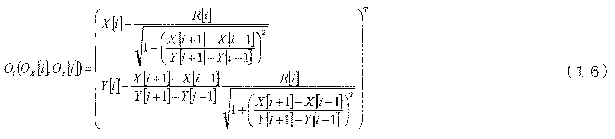
車両固定の移動座標系では、i番目の車両の横方向に対して合成加速度がなす角γ[i]は、以下数17の式で示すことができる。


<旋回中心と合成加速度の評価結果>
前節の式を用い、制御なし、 GVC、 Moment+制御について車両位置、旋回中心、車両に加わる合成加速度ベクトルの空間固定座標系に対する終端位置を計算した結果を図14、15、16に示す。コーナリングを開始する2秒から4秒までを0.5秒刻みで、そして、それ以外は1秒刻みでプロットしている。車両位置から、合成加速度ベクトルの終端位置を結ぶと、合成加速度ベクトルとなる(見やすいように10倍している(矢印)。単位は[G])。また、車両位置からその時点での瞬間旋回中心に向けて点線を引いている。
図中それぞれの丸枠は、瞬間旋回中心のX座標が最大になったとき、すなわち進入方向から、最も奥に旋回中心が移動したときの車両位置および、そのときの時間を示している。このときの時間および旋回中心座標、そして目標経路の旋回中心との偏差を図17にまとめる。
(ii)GVCが、旋回初期(図12の時系列データ参照)に合成ベクトルが旋回中心の方向に対して後ろ向きの角度を持ち、4秒には旋回中心が決まり、定常旋回が始まっているのに対し、(i)制御なしでは、旋回中心がLターンの終盤にまでどんどん奥にずれ込んで行き、図12(f)に示すようにタイヤドラッグにより速度が低下してから、ようやく旋回中心のずれが止まる。(iii)Moment+では、GVCと、制御なしの中間的な特性ではあるが、図12(h)の時系列データを見ると、GVCよりも早く横加速度は立ち上がっているにも関わらず、かなり制御なしに近い結果を示している。ここで、先に述べたようにMoment+のゲインを下げて、ヨーレイト応答をある程度まで下げた場合を考えると、さらに旋回中心のずれ込み度合い、収束までの時間も増加してしまうと考えられる。
図17旋回中心との偏差を見てみると、X軸方向の偏差が正の方向に大きいほど、またY軸方向の偏差が負の方向に大きいほど障害物に近くなる。結果的にGVCは制御なし、M+に比べて緊急回避性能が高いということがわかる。
以上の結果から、車両を質点とみなして解析的に検討を行った結果と、フルビークルモデルを用いた数値計算によっても、緊急回避時には減速度制御を優先する方が効果的であることが明らかになった。緊急回避動作において旋回促進側にヨーモーメントを制御する、すなわち旋回内側後輪に制動力を加えると、後輪の横力限界が低下し、横滑り角が大きくなり安定性が損なわれがちであるとともに、減速度を確保することができず、回避性能が低下しがちである。これに対して4輪に制動力を加えて専ら車両に減速度を加えるGVCにおいては、速度が低下するのみならず、旋回半径を小さく、かつ旋回中心を障害物から遠ざける効果が顕著である。したがって、緊急回避時にはM+制御によるモーメント制御に比べて、GVCによる減速度制御の割合を大きくした方が良いことが明らかになった。
<緊急回避時の減速度制御とヨーモーメント制御の割合配分指針(実車検証)>
さて、図18は、30m離してパイロンAとパイロンBを置き、パイロンAの右側をすり抜け、パイロンBの左側に移動する、レーンチェンジンジを模擬的に行った時の、操舵角、前後加速度、横加速度、そして車両速度について、ESCによるヨーモーメント制御のみを稼働した状態と、GVCとESCによるヨーモーメント制御の複合制御を稼働した状態を比較したものである。ESCによるヨーモーメント制御ロジックはM+そのものではないが、減速度制御とモーメント制御の比較評価としては、十分だと考えられる。
<緊急回避時の減速度制御とヨーモーメント制御の割合配分指針(実車検証)>
さて、図18は、30m離してパイロンAとパイロンBを置き、パイロンAの右側をすり抜け、パイロンBの左側に移動する、レーンチェンジンジを模擬的に行った時の、操舵角、前後加速度、横加速度、そして車両速度について、ESCによるヨーモーメント制御のみを稼働した状態と、GVCとESCによるヨーモーメント制御の複合制御を稼働した状態を比較したものである。ESCによるヨーモーメント制御ロジックはM+そのものではないが、減速度制御とモーメント制御の比較評価としては、十分だと考えられる。
ESCのヨーモーメントのみの制御に比べ、GVCとESCの連係制御では、操舵を開始した瞬間から減速度が働き操舵開始から0.5秒で速度が10km/hも低下している。
これにより、操舵角も少なくロールレイト、ピッチレイトが大幅に低減され、安全にレーンチェンジができていることがわかる。さらに、上で示したように、加加速度ゲインCxy、を大きくすることにより、同一タスクに対し、自動的に大きく速度を低減することが可能となり、大幅に回避性能が向上できる。ここでも、緊急回避時のGVCの優位性を確認することができた。
<アクチュエータ要件について>
一方、これらの横運動に連係した前後運動制御、モーメント制御は、通常領域から稼働させることにより、通常領域から制御効果があるというのが、その特徴ではあるが、全く別の観点で、このような制御を実現するためのアクチュエータのNVH(Noise、 Vibration、 Harshness)性能、あるいは耐久性能に高い要求が出される場合が多い。
<アクチュエータ要件について>
一方、これらの横運動に連係した前後運動制御、モーメント制御は、通常領域から稼働させることにより、通常領域から制御効果があるというのが、その特徴ではあるが、全く別の観点で、このような制御を実現するためのアクチュエータのNVH(Noise、 Vibration、 Harshness)性能、あるいは耐久性能に高い要求が出される場合が多い。
例えば、電機自動車、あるいはハイブリッド自動車などで、前後運動制御アクチュエータをモータとする場合や、制御ブースタ、あるいは電機式ブレーキを用いる場合は、耐久性、NVH性能は問題ない。しかしながら、ESCなどを通常領域から稼働させようとすると、これらの課題解決のためにはコストの増加を伴う。したがって低コストのESCを用いる場合、稼働領域・頻度を狭める必要性が生じる。
<まとめ>
以下に、ここまで検討してきた内容を用いて、緊急回避時の減速度制御とヨーモーメント制御の割合配分指針についてまとめて述べる。
(1) 横運動に連係した前後加速度制御において、横運動を特徴的に表す状態量(横加加速度)に対するゲインを大きくすることにより、速度低減効果、旋回中心を障害物から遠ざける効果などが大きくなり、回避性能が大幅に向上する。
(2) 横運動に連係したヨーモーメント制御において、横運動を特徴的に表す状態量(横加加速度)に対するゲインを大きくすると、旋回促進側の制御の場合、旋回内側後輪に大きな制動力を加えることになる。このような状況では後輪の横力限界が低下し、横滑り角が大きくなり安定性が損なわれがちである。従って、減速度を確保することができず、回避性能が低下しがちである。
(3) 前後加速度制御、ヨーモーメント制御ともに、ゲインを増加させるとぎくしゃく感が増加するが、制御効果とフィーリングがバランスするように、通常領域ではヨーモーメント制御(M+制御)の割合を増加させる方が好適である(このときの減速度はGVCと同じように合成加速度がなめらかに回転するような状況となる)。
(4) 制動アクチュエータの耐久性、あるいはNVH性能に課題がある場合は、稼働頻度を少なくする必要がある。
ということである。
<まとめ>
以下に、ここまで検討してきた内容を用いて、緊急回避時の減速度制御とヨーモーメント制御の割合配分指針についてまとめて述べる。
(1) 横運動に連係した前後加速度制御において、横運動を特徴的に表す状態量(横加加速度)に対するゲインを大きくすることにより、速度低減効果、旋回中心を障害物から遠ざける効果などが大きくなり、回避性能が大幅に向上する。
(2) 横運動に連係したヨーモーメント制御において、横運動を特徴的に表す状態量(横加加速度)に対するゲインを大きくすると、旋回促進側の制御の場合、旋回内側後輪に大きな制動力を加えることになる。このような状況では後輪の横力限界が低下し、横滑り角が大きくなり安定性が損なわれがちである。従って、減速度を確保することができず、回避性能が低下しがちである。
(3) 前後加速度制御、ヨーモーメント制御ともに、ゲインを増加させるとぎくしゃく感が増加するが、制御効果とフィーリングがバランスするように、通常領域ではヨーモーメント制御(M+制御)の割合を増加させる方が好適である(このときの減速度はGVCと同じように合成加速度がなめらかに回転するような状況となる)。
(4) 制動アクチュエータの耐久性、あるいはNVH性能に課題がある場合は、稼働頻度を少なくする必要がある。
ということである。
本発明においては、緊急回避が予想されるような危険ポテンシャルが高いときのみ、危険ポテンシャルが小さい、あるいはゼロの場合に比べ、横運動に連係した前後加速度制御(GVC)の稼働割合を大きくするとともに、ヨーモーメント制御(M+)の稼働割合を小さくし、速度を大きく低減するとともに、車両に加わる合力の速度と反対の方向成分(障害物から遠ざかる方向)を最大化することにより、緊急回避性能を向上するものである。
また、通所領域においては、ヨーモーメント制御(M+)の稼働割合を大きくし、GVCに比べて減速度を小さくし、フィーリングの向上を図るものである。
つぎに、危険ポテンシャルを定量的に評価する方法について述べる。これには、車両側のハード構成も関与するため、本発明の実施形態も含めて説明していくことにする。
危険ポテンシャルの評価としては、障害物との距離がまだ遠い状況、すなわち、まだ危険が顕在化していない場合と、実際に、急ブレーキや操舵により回避操作を行っているように、正に危険に遭遇している状態まで考えられる。
前者の危険ポテンシャルの評価については自車以外の環境、即ち進路上の障害物との相対位置、相対速度、相対加速度などを把握するための外部環境認識センサが必要となる。
後者の危険ポテンシャルの評価のためには、自車に搭載された操舵角センサ、ブレーキセンサ、あるいは加速度センサ、ヨーレイトセンサなど、操作入力あるいは車両挙動を計測し、それらが急峻に変化しているときに、危険に遭遇していると大まかには見て取ることができる。
さらに緊急回避性能の向上について考えてみる。勿論、後者の場合は直接的に自動ブレーキなどの前後運動制御が稼働している可能性がある状況であるが、前者の場合は、まだ回避動作がなされておらず、横運動が発生していない状況である。ここで、注意を要するのは緊急回避性能向上とは、必ずしも緊急回避動作時のアシストのみではなく、もしハンドルが切られて横運動が発生した時に、大きな減速度が発生するようにGVCの比率を大きくなる方向に変化させて、準備しておくということを含むということである(もし、ドライバあるいはシステムがハンドルを切らないと、顕在化しない保険のようなもの)。
以上に述べたような、顕在化していない危険ポテンシャルと、遭遇している危険を把握し、横運動に連係した前後運動制御による緊急回避性能を向上するために、横運動を特徴的に表す状態量(横加加速度、横滑り角変化など)に対するゲインGVCの比率を大きくすることを可能とする本発明の車両の運動制御装置を用いた車両の第一の実施例の全体構成を図19に示す。
最も理想的に実施するために、いわゆるバイワイヤシステムで構成されており、ドライバと操舵機構、加速機構、減速機構の間に機械的な結合は無い。実際の形態では、例えば操舵機構のみ機械結合を有し、ドライバが直接操舵角を決定するように構成しても、本発明を適用できる。
本実施例において車両0はエンジン1により左前輪61、右前輪62を駆動する後輪駆動車(Rear Engine Rear Drive:RR車)である(駆動方式は特に本発明に密接な関係は無い)。
まず、具体的な機器構成を述べる。左前輪61、右前輪62、左後輪63、右後輪64には、それぞれブレーキロータ、車輪速検出用ロータと、車両側に車輪速ピックアップが搭載され、各輪の車輪速が検出できる構成となっている。
ドライバのアクセルペダル10の踏み込み量は、アクセルポジションセンサ31により検出され、ペダルコントローラ48を経て、ADAS(Advanced driver assistance system)コントローラ40で演算処理される。そしてパワートレインコントローラ46は、この量に応じて、エンジン1の図示しないスロットル、燃料噴射装置等を制御する。
また、エンジン1の出力はパワートレインコントローラ46により制御される電子制御トランスミッション2を経由し、左後輪63、右後輪64に伝達される。電子制御トランスミッションとしては、トルクコンバータ式オートマチックトランスミッション、湿式多板クラッチ式オートマチックトランスミッション、セミオートマチックトランスミッション、無段変速機 (CVT)、デュアルクラッチトランスミッションでも良い。
ADASコントローラ40から出力される、速度低下(減速)指令に基づいて、エンジンから各輪までのギア比を切り替えることにより、減速作用を与えることができる。例えば、カーブなどの道路形状から計算された、あるいはあとで述べるGVCで求められる減速度、目標速度指令などの「横運動に連係した」前後運動指令に基づいて減速作用を発生させることができる。
アクセルペダル10にはまた、アクセル反力モータ51が接続され、ADASコントローラ40の演算指令に基づき、ペダルコントローラ48により、反力制御される。また、アクセルを閉じる方向の動き、特にアクセル閉方向の速度から、急なアクセルオフを感知し、「ドライバアクセル操作を用いた危険ポテンシャルの定量化」を行う。
車両0の操舵系は前輪操舵装置となっているが、ドライバの舵角とタイヤ切れ角の間に機械的な結合の無い、ステアバイワイヤ構造となっている。内部に舵角センサ(図示せず)を含むパワーステアリング7とステアリング16とドライバ舵角センサ33とステアリングコントローラ45で構成されている。
ドライバのステアリング16の操舵量は、ドライバ舵角センサ33により検出され、ステアリングコントローラ45を経て、ADASコントローラ40で演算処理される。そしてステアリングコントローラ45はこの量に応じて、パワーステアリング7を制御する。
ステアリング16には、また、ステア反力モータ53が接続され、ADASコントローラ40の演算指令に基づき、ステアリングコントローラ45により、反力制御される。また、これと同時にADASコントローラ40は、ドライバのステアリング操作量、特に操舵角速度から、急ハンドルを感知し、「ドライバ操舵操作を用いた危険ポテンシャルの定量化」を行う。ドライバのブレーキペダル11の操作量(踏み込み量)は、ブレーキペダルポジションセンサ32により検出され、ペダルコントローラ48を経て、ADASコントローラ40で演算処理される。
左前輪61、右前輪62、左後輪63、右後輪64には、それぞれブレーキロータが配備され、車体側にはこのブレーキロータをパッド(図示せず)で挟み込むことにより車輪を減速させるキャリパーが搭載されている。
左前輪61、右前輪62、左後輪63、右後輪64には、それぞれブレーキロータが配備され、車体側にはこのブレーキロータをパッド(図示せず)で挟み込むことにより車輪を減速させるキャリパーが搭載されている。
キャリパーは油圧式、あるいはキャリパー毎に電機モータを有する電機式である。油圧式の場合、従来の負圧ブースタに代え、中空モータとその内部のボールねじをアクチュエータとしてマスタシリンダ油圧を発生させるというシンプルな方式を採用しハイブリッド電気自動車や電気自動車の走行用モータによる回生ブレーキと協調して、自然なペダルフィーリングで必要な制動力を確保できる電動アクチュエーションを用いても良いし、ITS対応のESC(Electronic Stability Control)の多筒プランジャポンプ、あるいはギヤポンプで加圧してもよい。
それぞれのキャリパーは、基本的にはADASコントローラ40の演算指令に基づき、ブレーキコントローラ450により制御される。また、このブレーキコントローラ450には前出したように各輪の車輪速、操舵角、ヨーレイト、前後、横加速度などの車両情報がADASコントローラ40を経由して、あるいは直接入力され、車速V、車両横滑り角などが計算される。
そしてこれらの情報はADASコントローラ40内にて、共有情報として、常にモニタリングされている。
そしてこれらの情報はADASコントローラ40内にて、共有情報として、常にモニタリングされている。
ブレーキペダル11にはまた、ブレーキペダル反力モータ52が接続され、ADASコントローラ40の演算指令に基づき、ペダルコントローラ48により、反力制御される。また、これと同時にADASコントローラ40は、ドライバのブレーキペダル操作量、特にペダル速度から、急ブレーキを感知し、「ドライバブレーキペダル操作を用いた危険ポテンシャルの定量化」を行う。
つぎに本発明の運動センサ群について述べる。
図7に示すように、横加速度センサ21と前後加速度センサ22は、重心点近辺に配置されている。また夫々の加速度センサの出力を微分して加加速度情報を得る、微分回路23、24が搭載されている。本実施例では微分回路の存在を明確化するために各センサに設置しているように図示したが、実際はADASコトローラ40に直接加速度信号を入力して各種演算処理をしてから微分処理をしてもよい。
また、特開2011-7353号公報に示されるように、車両速度、操舵角、車両運動モデルを用いた推定ヨーレイト・横加速度を用いて横加加速度を得てもよいし、これらを例えばセレクト・ハイなどの処理により組み合わせて用いてもよい。また、ヨーレイトセンサ38の信号を用いて車両運動モデルによる推定精度を向上するような構成となっている。
さらに運動センサ群を用いて、路面の状態(摩擦係数など)を推定したり、路面勾配などを推定し、「走行環境に対する危険ポテンシャルの定量化」を行う。ここで注意を要するのは、路面勾配が大きい下り坂の場合は危険ポテンシャルが高く、横運動連係ゲインを向上する方向で良いが、路面摩擦係数が低い場合は、危険ポテンシャルは高いが、横運動連係ゲインを向上すると車輪ロックの危険性が生じる。したがって、このような場合はゲインを増加するとともに、特許4920054号公報に示されているような車輪過スリップ防止制御を組み込む必要がある。
また、車両0には、ドライバへアシスト情報(システム稼働情報)を伝えるHVI(Human Vehicle Interface)55が搭載されている。HVI55は、ドライバが目にすることが出来る画面、警告音、あるいは各ペダルの反力制御と連携して、複数の手段でドライバにシステム稼働情報を伝える。
さらに、車両0には、ステレオカメラ70とステレオ画像処理装置701が搭載されている。ステレオカメラ70は、左右方向に2つの撮像素子であるCCDカメラで構成されている。
2つのCCDカメラは、たとえば車室内のルームミラー(図示せず)を挟むような形で配置され、車両前方の対象物を車両固定系の異なる座標から個別に撮像し、2つの画像情報をステレオ画像処理装置701に出力する。なお、ここではCCDカメラを用いたが、CMOSカメラを用いても良い。
ステレオ画像処理装置701には、ステレオカメラ70から画像情報が入力されるとともにADASコントローラ40を経由してブレーキコントローラ450から車速Vが入力される。これらの情報に基づき、ステレオ画像処理装置701は、ステレオカメラ70からの画像情報に基づいて車両0前方の立体物データや白線データ等の前方情報を認識し、自車走行路を推定する。
さらに、ステレオ画像処理装置701は、自車が、今後走行していく路上に障害物や先行車等の立体物の存在を調べ、最も近い立体物を衝突防止のための障害物として認識し、ADASコントローラ40に出力する。そして、ADASコントローラ40は、自車速度、相対位置、相対速度、相対加速度など(これを走行環境データと呼ぶ)に基づいて、「外部情報による、危険ポテンシャルの定量化」をおこなう。
図20に、本発明のADASコントローラ40とブレーキコントローラ450の内部構成を示す。ブレーキコントローラ450は、基本構成として、ACC、プリクラッシュブレーキを可能とする減速度制御入力、車線逸脱防止システム用のヨーイングモーメント入力用のポートを持つ。CAN(Control Area Network)のI/Oポートの入出力情報に基づき、適切な方法で、制御指令をブレーキコントローラ450側に入力すれば、車両の減速度と、ヨーイングモーメントを制御できる。もちろん、本来のESC動作によるヨーイングモーメント指令も発生されるため、入力ポート側の指令に上限値を設け、一時無効とするなどの調停動作(四輪制動力配分)を行うロジックもESC制御部451に組み込まれている。
ADASコントローラ40には、ステレオカメラ、レーダ、GPSなどの外部情報と、車速、操舵角、加速度、ヨーレイトなどの車両情報を取り込み、危険度を推定する、つまり、入力された外界情報及び車両情報に基づいて、車両の危険ポテンシャルを推定する危険ポテンシャル推定部41を有する。また、加減速度コントローラ43とヨーイングモーメントコントローラ44を有する。本実施例においては、車両前後運動制御部である加減速度コントローラ43には、GVCロジックが入っており、数1に基づいて、「横運動に連係した前後運動」が加減速度の指令値として求められる、つまり、車両の横加加速度と予め定めたゲインとに基づいて車両の前後運動制御指令を生成する。また、車両ヨーイング運動制御部であるヨーイングモーメントコントローラ44には、Moment Plusロジックが入っており、数2に基づいて「横運動に連係した前後運動」がヨーイングモーメントの指令値として求められる、つまり車両の横加加速度と予め定めたゲインとに基づいて車両のヨーイング運動制御指令を生成する。
以上から、本発明の車両の運動制御装置であるADASコントローラ40は、入力された外界情報及び車両情報に基づいて、車両の危険ポテンシャルを推定する危険ポテンシャル推定部41と、車両の横加加速度と予め定めたゲインとに基づいて車両の前後運動制御指令を生成する加減速度コントローラ43とヨーイングモーメントコントローラ44と、加減速度コントローラ43で生成された車両の前後運動制御指令とヨーイングモーメントコントローラ44で生成された車両のヨーイング運動制御指令の比率を調整する、つまり減速度制御とモーメント制御の比率、割合を調整する比率調整部42と、を有し、比率調整部42は、危険ポテンシャル推定部で推定された危険ポテンシャルに基づいて減速度制御とモーメント制御の比率を調整することが特徴である。
また、ADASコントローラ40は、これら「横運動に連係した前後運動」のゲイン(加減速度コントローラ43においては数1の車両横加加速度ゲイン(第1のゲイン)Cxy、ヨーイングモーメントコントローラ44においては、数2の車両横加加速度ゲイン(第2のゲイン)Cmn)を掛けて、減速度とモーメントの、それぞれの指令値を決定する。つまり、車両前後運動制御部である加減速度コントローラ43は、車両の横加加速度と予め定めた第1のゲイン(Cxy)に基づいて車両の前後加速度指令値を算出して前後加速度指令値を出力し、車両ヨーイング運動制御部であるヨーイングモーメントコントローラ44は、車両の横加加速度と予め定めた第2のゲイン(Cmn)に基づいて車両のヨーモーメント指令値を算出してヨーモーメント指令値を出力する。
また、比率調整部42では、危険ポテンシャル推定部41が推定する危険ポテンシャルに基づき、危険ポテンシャルが予め定めた値より高い時には、危険ポテンシャルが低い時に比べ、減速度制御の比率がモーメント制御の比率に比べて大きくなるように調整する。また、危険ポテンシャル推定部41で危険ポテンシャルが検出された場合、検出されない場合に比べて、車両の前後運動制御指令の比率を車両のヨーイング運動制御指令の比率より大きくなるように、又は車両の前後運動制御指令が大きくなり、車両のヨーイング運動制御指令が小さくなるように調整する調整する。
比率調整部42では、減速度対ヨーメントの比率RGMが計算、あるいはマップ参照される(0≦RGM≦1、0がモーメント制御のみ、1が減速度制御のみ)。加減速度コントローラ43により計算される減速度指令に、ゲインとしてRGMが、掛けられブレーキコントローラ450の減速度ポートに送られる。また、これと同時に、ヨーイングモーメントコントローラ44により計算されるモーメント指令にゲインとして(1-RGM)が、掛けられブレーキコントローラ450のモーメントポートに送られる。つまり比率調整部は、危険ポテンシャル推定部41で推定された危険ポテンシャルに基づいて、減速度対ヨーメントの比率(RGM、0≦RGM≦1)を算出し、前後加速度指令値に、その比率(RGM)を乗じた値を新たな前後加速度指令値とし、ヨーモーメント指令値に、1からその比率を減じた値(1-RGM)を乗じた値を新たなヨーモーメント指令値として調整される。
その際、比率調整部42は、危険ポテンシャル推定部41で推定された危険ポテンシャルが予め定めた値より高い場合、前記値より低い場合に比べて、減速度対ヨーメントの比率(RGM)が大きくなるように調整する、又は、危険ポテンシャルが検出されない場合、減速度対ヨーメントの比率(RGM)をゼロとなるように調整する。
つぎに危険ポテンシャルの定量的評価方法を示す。
例えば、図9に示すようにx方向に走行中の自車両0の前に、先行車101が走行しており、自車両0の位置がxf、速度がvf、加速度がafで、先行車101の位置がxp、速度がvp、加速度がapとすると、それぞれの相対位置は、xr=xf-xp、相対速度はvr=vf-vp、相対加速度は、ar=af-apとなる。
これらの値を用いて、以下のような危険ポテンシャルが従来提案されている。
(1)TTC(Time-To-Collision:衝突余裕時間)(以下、数19を参照)

(2)KdB(接近離間状態評価指標)(以下、数20を参照)

(3)THW(Time-Head Way:車間時間)(以下、数21を参照)

(4)1/TTC(Time-To-Collisionの逆数)(以下、数22を参照)

(5)RF(Risk Feeling)(以下、数23を参照)

これらの危険ポテンシャルは、ステレオカメラのみならず、ミリ波レーダ、レーザレーダなどの前方との測距センサを用いても得ることが出来る。本実施例では、自車両0の先行車101あるいは、障害物(図示せず)への接近に伴い増加傾向を示す、数19の1/TTC(Time-To-Collisionの逆数)を用いることにする。
図22に、1/TTCと、相対的な障害物との距離Di、そして衝突危険ポテンシャルの関係を模式的に示す。先行車101(止まっている場合、障害物)との距離が縮まると、1/TTCが増加し、危険ポテンシャルが向上している様子が示されている(ただし、相対速度は一定と想定している)。
例えば障害物との距離をD4として遠い場合、1/TTCは、1/tc0と、小さい値となり、このときに危険ポテンシャルはRP0となり危険は無い(RP0≒0)。
一方、距離が短くなると衝突の危険性は急激に高くなり、距離D1より短くなると危険ポテンシャルは大幅に大きくなる。この危険ポテンシャルの定量化は、図22の実線のように段階的にしても良いし、図22の点線のように、連続的にしても良い。このように1/TTCにより、危険ポテンシャルの定量的評価が可能となる。
図23は、ドライバ操舵操作を用いた危険ポテンシャルの定量的評価を車載のステアリング角センサが出力する操舵角速度情報に基づいて行った例を示している。一般的に緊急操舵を行い、衝突を回避しているときには、操舵速度が早くなる。したがって、操舵速度が遅い場合は、通常運転時で、早い場合は、危険ポテンシャルが高い時と位置づけることができる。
操舵角速度が正の場合、左側に操舵を増し、操舵角速度が負の場合は、右に操舵を増している状態である。
図23では、危険ポテンシャルが左右の操舵角速度に対して対称になっているが、「右側通行」「左側通行」に対して左右、非対象にしても良いし、カウンターステア(有る方向に操舵している状態で、逆方向に急激に戻す)などを考慮して、操舵角速度のみならず、操舵角と操舵角速度の2次元マップとしても良い。さらにこの危険ポテンシャルの定量化は、図22の実線のように段階的にしても良いし、図22の点線のように、連続的にしても良い。
図24は、ドライバ操舵操作により発生した横運動を用いた危険ポテンシャルの定量的評価を操舵角に対するモデル推定の規範運動と、実際にセンサで計測される実運動との偏差(D)の情報に基づいて行った例を示している。車両横運動モデルとしては、例えば、特開2010-076584にて開示されている、伝達関数表記が良く知られている。この車両横運動モデルを用いると、操舵角入力に対する、ヨー応答、横すべり角、横加速度、あるいは横加加速度が計算可能となる。車両横運動モデルを用いて計算された値は、タイヤ発生コーナリングフォースがタイヤ横滑り角と線形関係にある間は、実測値と一致するように調整されている。一方、緊急回避時などの場合、大舵角となったり、横加速度が大きくなったりして、タイヤ横滑り角とコーナリングフォースの線形性が崩れる。このような状況では、モデル推定の規範運動と実運動の間に大きな乖離が生じるようになる。結果的には、この乖離(偏差(D))が小さいうちは、緊急度は低く、乖離が大きくなるにつれて、緊急度が増加していると考えることができる。したがって、規範運動と実運動との偏差(D)小さい場合は、通常運転時で、大きい場合は、危険ポテンシャルが高い時と位置づけることができる。さらにこの危険ポテンシャルの定量化は、図24の実線のように段階的にしても良いし、図22の点線のように、連続的にしても良い。
また、本実施例では図面は省略するが、アクセルオフ側のペダル角速度、ブレーキ踏みこみ側のペダル角速度についても「角速度が大きい時には危険ポテンシャルが高い」として危険ポテンシャルを定義し、危険ポテンシャルの定量的評価を行ってもよい。
図25は、図22、図23、図24の定量的な危険ポテンシャルに対し、定性的な危険度の評価指標を対応させ、また、図26は、本発明の実施例において危険ポテンシャルが定量化された場合の各定量値に対するシステムの稼働状況を示した表である。
「自動ブレーキ」、「横運動に連係した前後運動連係ゲインの調整」、HVI55の「マルチインフォメーションディスプレイの表示」、「ブザー」、「ステア反力、ペダル反力等の振動」など、システムの稼働指令の計算はADASコントローラ40が、一括して管理している。以下、危険ポテンシャルとシステムの稼働について概説していく。
RPOは、「危険なし」の状況を示しており、通常の運転状況では、ほとんどこの状態である(発生頻度が高い)。
このような状態では衝突回避のための自動ブレーキ制御(横運動に連係していない直線ブレーキ)の必要は無い。また、「横運動に連係した前後運動」は、緊急回避などの急激な横移動をアシストする可能性は低く、このため制御による減速度の大きさは、横運動によるロールと前後運動によるピッチがドライバにとって違和感のない範囲に留めておくことが重要となる。
そして、ドライバが直進修正操舵を加えたり、緩いレーンチェンジ(時間をかけて別のレーンに移動)を行ったりするときに、大きな減速度によって「引っかかり感」が生じないようにしておくことが肝要である。
相対的に減速度を低減するためには、GVCによる減速度制御の比率を小さくし(本実施例では0~0.25)、M+によるモーメント制御の比率を大きくする(1.0~0.75)ことにより、横運動に連係した運動制御のメリットを保ちながら、違和感を低減することが出来る。また、極端な例として、このときの比率のみならず、Cxy、Cmなどの横運動連係ゲインをゼロにしておくと、通常時は減速用アクチュエータの稼働頻度を著しくさげることができ、耐久性要件を大幅に緩和することができる。また、NVH性能が低い安価な減速用アクチュエータを搭載した車両に対しても、NVH性能が問題になる確率を大幅に低減できる。このことについては、図31、32、33を用いて、危険ポテンシャルに基づいて、減速度制御とヨーモーメント制御の比率を変化させるのみではなく、それぞれの制御指令を決定するゲインを変化させることに言及した、第2の実施例において述べることにする。
RPO「危険なし」の状況では、もちろんHVI55のマルチインフォメーションディスプレイ、ブザー、ステア反力、ペダル反力等の振動制御は行わない。
つぎにRP1は「衝突の可能性がある」という状況で、加減速無くこのままの状態を続けると、衝突する状況である。したがって、ドライバに対して、ブレーキ(エンジンブレーキを含む)を促す必要がある(この段階では自動ブレーキ制御は行わない)。
このとき、マルチインフォメーションディスプレイには、前方車両表示とともに前方注意と表示するとともに、「ピピピ…。」というブザーを鳴らし、ドライバに衝突の可能性を伝える。さらにはステア反力、ペダル反力等に弱い振動を与え注意を促す。
RP1のときには、減速度対ヨーメントの比率RGMは、RP0のときに比べて大きく設定し(0.2⇒0.4)、減速度制御の比率を高め、万一の衝突を避ける操舵回避のための回避ポテンシャルを向上させておく(操舵が成されない場合は、車両運動に影響を及ぼすものではない)。
危険ポテンシャルがRP2となると「衝突の可能性が高い」状況となり、特許文献1と同様に、ドライバがブレーキをかけなくても、弱い自動ブレーキ(警報ブレーキ)がかかる。この自動ブレーキは、横運動に連係したものではなく、数1のGx_DCにあたるものである。減速度対ヨーメントの比率RGMは、RP1のときに比べて大きく設定し(0.4→0.6)、減速度制御比率を向上し、緊急回避に備えて回避ポテンシャルをさらに向上させておく。ディスプレイ、ブザーは、RP1と同じであるが、ステア反力、ペダル反力はRP1に比べて、大きな振動とする。
さらに、RP3は、「衝突の可能性が非常に高い」状況であり、強い自動ブレーキ(緊急ブレーキ)がかかる。さらに減速度対ヨーメントの比率RGMはRP2に比べ、さらに大きくする(0.6→0.8~1.0)。これにより、モーメントを作る際に、減速方向の力を緩める比率を小さくすることができ、4輪で最大限の減速度を得ることが出来、緊急回避に有利となる。ブザー音は連続の「ピーー」という連続音になり、ステア反力、ペダル反力をRP2に比べて、大きな振動とする。
図27は、これらの状況を模式的に示す図である。上記数1で表せる減速度制御GVCと数2で表せるモーメント制御M+は、符号関数、一次遅れなどを省略して考えると図中にあるように、減速度指令値は、車両横加加速度に横運動連係ゲインである-Cxyを掛け合わせたものとなり、モーメント指令値は、車両横加加速度に横運動連係ゲインであるCmを掛け合わせたものとなる。さらに比率調整部42において、モーメント指令値には、(1-RGM)が掛けられ、減速度指令値にはRGMが掛けられ、それぞれブレーキコントローラ450のモーメントポート、減速度ポートに送られる。
障害物(図27ではエルク)に近づいていくにつれ、減速度対ヨーメントの比率RGMを大きく設定し減速度制御の比率が増加するように調整し、警報後の回避、警報ブレーキ後の回避、緊急ブレーキ後の回避を行う。
また、減速度対ヨーメントの比率RGMは定量化された危険ポテンシャルの増加に伴い、段階的に増加するように変えても、連続的に増加するように変えても良い。
以上のように、減速度対ヨーメントの比率RGMを変化させることにより、RP0の通常時には、M+によるモーメント制御のみを行い、結果的に違和感の少ない小さな減速度とし、RP3のときは、GVCによる減速度制御のみを行い、最大限の緊急回避ポテンシャルが得られる構成を実現できる。具体的には、RP0の通常時には、回避のための左移動へのヨー運動を促進するように、左後輪に加えられていたブレーキが、徐々に前輪、あるいは右輪にも加えられるようになり、RP3では、左右同じだけのブレーキ力に近づくようになる。
図28には、これらの制御機能を、単位横運度(例えば横加加速度1m/s3)あたりの減速度指令値、モーメント指令値を縦軸、危険リスクを横軸として示したものである。危険リスクとしてRPs<RPLの場合、 RPLに対する減速度指令値GmL、RPsに対する減速度指令値GmSとすると、GmL>GmSの関係となる。また、RPLに対するモーメント指令値MmL、RPsに対する減速度指令値MmSとすると、MmL<MmSの関係となる。
図29は、図27の車両の運動制御システム構成をより明確に示した概念図である。
ステレオカメラなど外界センサにて障害物との相対距離、相対速度、相対加速を検出し、ADASコントローラ40は、この情報を用いて例えば1/TTCという判断基準で危険ポテンシャルを定量化する。ADASコントローラ40においては、危険度に応じて、減速度対ヨーメントの比率RGMを記憶しているマップなどで構成される比率調整部42により、加減速度コントローラ43で演算された、減速度指令にRGMを乗じ、ヨーイングモーメントコントローラ44で演算された、モーメント指令に(1-RGM)を乗じ、それぞれの指令値をブレーキコントローラ450に、CAN信号などとして送信する。比率調整部42は、予め記憶された危険ポテンシャルに応じた減速度対ヨーメントの比率が記されたマップを用いて、推定された危険ポテンシャルに対応するゲインが出力される構成にしても良い。
ここまでの実施例では、減速度指令とモーメント指令は専らブレーキコントローラ450に送信されるとしていたが、ADASコントローラ40は、ブレーキコントローラ450のみならず、回生制動用のモータ1、あるいはCVT2などにも減速、モーメント指令を送り、危険ポテンシャル基づく、好適な横運動に連係した前後運動制御とモーメント制御を実現してもよい。
もし、ドライバが回避操作を行わない場合には、横運動に連係した減速指令、モーメント指令は発令されないが、危険ポテンシャルに基づく直線制動制御は勿論行われることになる。システムとしては、緊急回避操舵操作が行われた場合の回避ポテンシャルを向上させてはいるが、横運動に連係した前後運動制御の稼働は、自動的に行われるものではなく、ドライバの意思(操舵操作)に基づいて、初めて行われるものであることに注意を要する。
また、回避動作時に、高度な運転操作により回避を試みるドライバに対しては、ドライバ動作と「横運動に連係した前後運動制御」が干渉を及ぼす可能性もぬぐいきれない。
例えば、後輪駆動車両の場合、操舵操作と合わせて、アクセルを全開にして、駆動力により後輪横力を低減させ、急激にヨーイング運動を立ち上げて回避を行うかもしれないし、パーキングブレーキを操作して後輪をロックさせて、いわゆるスピンターン状態で回避を行うかもしれない。このような状況に対しては、アクセル、あるいはパーキングブレーキの操作量にあらかじめ設定した閾値を設け、この閾値を超えたときには、「横運動に連係した減速度、モーメント指令」の横運動連係ゲインを危険ポテンシャルに応じて決定されたゲインに比べて小さくするように設定している。
具体的には、横運動に連係した前後運動制御指令は、ドライバからのアクセル操作指令が、予め定めた閾値を超えて入力された場合にゼロとなる。
図30は、「警報ブレーキ」「緊急ブレーキ」のような自動ブレーキによる直線減速とGVC、M+による横運動に連係した減速制御、モーメント制御との連係状況を示す図である。
特に左の図は、車両前後加速度をx軸に、車両横加速度をy軸とし、車両の合成加速度ベクトルG(Gx、Gy)がどのように推移するかを示す”g-g”ダイアグラムを示している。
図27に示すように、本発明においては、「警報ブレーキ後の回避」「緊急ブレーキ後の回避」を考慮する必要がある。先にも述べたとおり、特許文献1を参照して構成し、図26、図27に示した各自動ブレーキ制御は、前後運動のみを制御した直線減速である。
したがって図30の”g-g”ダイアグラムに示すと、x軸上のみの減速度推移となる(数1のGx_DC)。これに対して、この直線減速を考慮せず、ステアリングによる回避動作時のGVCとM+での減速度と横加速度の合成加速度ベクトルG(Gx、Gy)の推移を示したものが、図30中の曲線である。その始点は原点からで、左への回避の際は正の横加速度と、これに連係して前後方向の減速度が加わるので横加速度が増加して他車線に移動していくときは、第4象限での推移となる。
一方、特許文献1にも記載されているように、警報ブレーキあるいは緊急ブレーキなどの自動ブレーキ制御は、ドライバによる操舵角、あるいは操舵角速度が大きくなると、制動制御を禁止する時間を設定しているために、回避動作を開始すると、自動ブレーキ制御は、解除される。ここでGVCとM+により、横運動に連係した減速度制御とモーメント制御は行われるのであるが、自動ブレーキ制御が解除されGVCあるいはM+による減速が立ち上がってくるまでの間、一瞬減速度の落ち込みが発生する可能性がある。これはいわゆる「G抜け(ブレーキ抜け)」として、フィーリングの悪化を招くだけではなく、ピッチングによるドライバ視点の急激な変動、あるいはタイヤの接地荷重の変動の原因となり、操舵による回避性能の低下が懸念される。
本発明においては、ADASコントローラ40の中に、自動ブレーキによる直線減速指令が、操舵開始タイミングで急激に(ステップ状に)低下しないように、例えば一次遅れフィルター(ローパスフィルタ)のような平滑手段により、操舵操作により発生する横運動に連係したGVCとM+による減速との間を、滑らかにつなぎ合わせ、図30にあるように、自動ブレーキによる直線減速(A点)からB点を通り、横運動のみのC点へと推移させることができる。
これにより、ドライバの視点の安定、接地荷重変動が低減でき、緊急時でも落ち着いて回避動作を行いやすくなる。
つぎに、危険ポテンシャルにもとづき、減速度対ヨーメントの比率RGMを変化させるだけではなく、横運動に連係した減速度制御、横運動に連係したモーメント制御の強さ(ゲイン)をも変化させる反発明の第2の実施例について、図31、32を用いて述べる。基本構成は、図29と類似しているが、危険ポテンシャルに基づいて、加減速度コントローラ43により計算される減速度指令値とヨーイングモーメントコントローラ44により計算されるモーメント指令値に乗じる、ゲインKを、例えばマップ460,461などに記憶しておくゲイン調整部を有している。マップ460,461には、図27の減速度対ヨーメントの比率RGMと同様に、危険ポテンシャルが増加すると、ゲインK増加するような関係が記憶されている。
特に、RP0に対するゲインKRP0=0と設定すると、通常領域でのブレーキアクチュエータの稼働頻度をゼロとすることができる。
つぎに、危険ポテンシャルにもとづき、減速度対ヨーメントの比率RGMを変化させるだけではなく、横運動に連係した減速度制御、横運動に連係したモーメント制御の強さ(ゲイン)をも変化させる反発明の第2の実施例について、図31、32を用いて述べる。基本構成は、図29と類似しているが、危険ポテンシャルに基づいて、加減速度コントローラ43により計算される減速度指令値とヨーイングモーメントコントローラ44により計算されるモーメント指令値に乗じる、ゲインKを、例えばマップ460,461などに記憶しておくゲイン調整部を有している。マップ460,461には、図27の減速度対ヨーメントの比率RGMと同様に、危険ポテンシャルが増加すると、ゲインK増加するような関係が記憶されている。
特に、RP0に対するゲインKRP0=0と設定すると、通常領域でのブレーキアクチュエータの稼働頻度をゼロとすることができる。
図32に単位横運動 (例えば横加加速度1m/s3) あたりの減速度指令値とモーメント指令値(比率補正前)を縦2軸で示す。危険リスクとしてRPS<RPLの場合、 RPLに対する減速度指令値GpL、RPsに対する減速度指令値GpSとすると、GpL>GpSの関係となる。また、RPLに対するモーメント指令値MpL、RPsに対する減速度指令値MpSとすると、MpL>MpSの関係となる。
比率調整部42では、ゲイン調整部内でのブレーキ力配分調整手段452、453でゲインKを乗じた制御指令値(Gp、Mp)のうち、減速度指令値Gpに、RGMを乗じ、モーメント指令値Mpに(1-RGM)を乗じ、それぞれの指令値をブレーキコントローラ450に、CAN信号などとして送信する。
このように構成すると、RPO「危険なし」の状況では、減速度制御による減速度、モーメント指令により結果として発生する減速度の両方を根本的に小さくすることができ、フィーリングの向上を図ることができるとともに、以下に示すようなアクチュエータの使用頻度の低減が可能となる。これに基づく減速アクチュエータに対する要件の緩和について最後に述べることにする。
図29に示すような減速アクチュエータのうち、ポンプアップした油圧を用いて減速させるいわゆるESCを用いたものは、他のモータによる回生、あるいはCVT等に比べて、ポンプ部分の耐久性が課題となる場合が多い。さらに作動時の音なども課題となる場合が多い。これらの課題に対しては、多気筒のプランジャポンプやギヤポンプを用いた、いわゆる「プレミアム仕様」にて通常領域からの稼働に対応している。一方、価格レンジの低い車両においてもESCは義務付けられているが、これらの車両にはコストの制約上採用できない。このような価格レンジの低い車両においても、本発明を適用し、緊急回避性能を向上することが出来る。
ADASコントローラ40のゲイン調整部において、図31、32のように危険ポテンシャルがRP0すなわち危険無しの状態での横運動連係ゲインを「ゼロ」に設定すると、危険が無い状態では、横運動が発生しても、減速指令、モーメント指令ともゼロとなり減速アクチュエータは稼働しない。
ここで、図33の一番上の危険リスク頻度グラフを見ると、通常時(危険なし)が生涯運行状況のうちのほとんどであることがわかる。したがって通常時のゲインをゼロにしておくことにより、耐久性に大きな影響を与える稼働時間を大幅に提案できる。
例えば、本発明の第2の実施例を採用せず、「危険なし」状態(RP0)から「衝突の可能性が非常に高い」状態(RP3)まで同じゲイン(正規化ゲイン1.0)とした場合に比べ、定量評価された危険度に対し、危険度が増すにつれて以下のように
RP0に対するゲイン 0.0
RP1に対するゲイン 1.0
RP2に対するゲイン 1.5
RP3に対するゲイン 2.0
ゲインを増加させる本発明の制御方法を採用すると、生涯正規化稼働時間(稼働強さも考慮)を2.3%にまで低減できる。また、危険リスクが高い時は、多少の作動音、振動、ぎくしゃく感は、容認されるため、価格レンジの低い車両においても(ESCは標準装着であるため)本発明により、緊急回避性能を向上することが出来る。
RP0に対するゲイン 0.0
RP1に対するゲイン 1.0
RP2に対するゲイン 1.5
RP3に対するゲイン 2.0
ゲインを増加させる本発明の制御方法を採用すると、生涯正規化稼働時間(稼働強さも考慮)を2.3%にまで低減できる。また、危険リスクが高い時は、多少の作動音、振動、ぎくしゃく感は、容認されるため、価格レンジの低い車両においても(ESCは標準装着であるため)本発明により、緊急回避性能を向上することが出来る。
以上、横運動に連係した減速度制御とモーメント制御について、減速度制御の比率を増加した時の制御効果、体感上の課題、アクチュエータ課題について述べ、本発明による具体的な危険ポテンシャルの定量化方法、危険ポテンシャルに基づく減速度対ヨーメントの比率RGMの調整方法、また横運動連係ゲインの調整による効果を示してきた。
本発明によると、通常時には、ぎくしゃくせず、緊急回避操舵時には確実にドライバをアシストする車両の運動制御装置を提供することができる。また発生頻度が非常に高い「通常領域」のゲインをゼロにすることにより、耐久性、NVH性能が低い制動アクチュエータを採用できる可能性を広げ、低コストレンジの車両にまで、上述のメリットを享受することを可能と提供できる。
0 車両
1 エンジン
2 電子制御トランスミッション
7 パワーステアリング
10 アクセルペダル
11 ブレーキペダル
16 ステアリング
21 横加速度センサ
22 前後加速度センサ
23、24、 微分回路
31 アクセルポジションセンサ
32 ブレーキペダルポジションセンサ
33 ドライバ舵角センサ
38 ヨーレイトセンサ
40 ADASコントローラ
41 危険ポテンシャル推定部
42 減速度対ヨーモーメント比率調整部
43 加減速度コントローラ
44 ヨーイングモーメントコントローラ
450 ブレーキコントローラ
451 ESC制御部
452 ブレーキ力配分調整手段
45 ステアリングコントローラ
46 パワートレインコントローラ
48 ペダルコントローラ
51 アクセル反力モータ
52 ブレーキペダル反力モータ
53 ステア反力モータ
61 左前輪
62 右前輪
63 左後輪
64 右後輪
70 ステレオカメラ
701 ステレオ画像処理装置
1 エンジン
2 電子制御トランスミッション
7 パワーステアリング
10 アクセルペダル
11 ブレーキペダル
16 ステアリング
21 横加速度センサ
22 前後加速度センサ
23、24、 微分回路
31 アクセルポジションセンサ
32 ブレーキペダルポジションセンサ
33 ドライバ舵角センサ
38 ヨーレイトセンサ
40 ADASコントローラ
41 危険ポテンシャル推定部
42 減速度対ヨーモーメント比率調整部
43 加減速度コントローラ
44 ヨーイングモーメントコントローラ
450 ブレーキコントローラ
451 ESC制御部
452 ブレーキ力配分調整手段
45 ステアリングコントローラ
46 パワートレインコントローラ
48 ペダルコントローラ
51 アクセル反力モータ
52 ブレーキペダル反力モータ
53 ステア反力モータ
61 左前輪
62 右前輪
63 左後輪
64 右後輪
70 ステレオカメラ
701 ステレオ画像処理装置
Claims (20)
- 入力された外界情報及び車両情報に基づいて、車両の危険ポテンシャルを推定する危険ポテンシャル推定部と、
車両の横加加速度と予め定めたゲインとに基づいて車両の前後運動制御指令を生成する車両前後運動制御部と、
車両の横加加速度と予め定めたゲインとに基づいて車両のヨーイング運動制御指令を生成する車両ヨーイング運動制御部と、
前記車両の前後運動制御指令と車両のヨーイング運動制御指令の比率を調整する比率調整部と、を有し、
前記比率調整部は、前記危険ポテンシャル推定部で推定された前記危険ポテンシャルに基づいて前記比率が調整される車両の運動制御装置。 - 請求項1記載の車両の運動制御装置において、
前記比率調整部は、前記危険ポテンシャル推定部で前記危険ポテンシャルが検出された場合、検出されない場合に比べて、前記前後運動制御指令の比率をヨーイング運動制御指令の比率より大きくなるように調整する車両の運動制御装置。 - 請求項1又は2記載の車両の運動制御装置において、
前記比率調整部は、前記危険ポテンシャル推定部で前記危険ポテンシャルが検出された場合、検出されない場合に比べて、前記前後運動制御指令が大きくなり、ヨーイング運動制御指令が小さくなるように調整する車両の運動制御装置。 - 請求項1記載の車両の運動制御装置において、
前記車両前後運動制御部は、車両の横加加速度と予め定めた第1のゲインに基づいて車両の前後加速度指令値を算出して、前後加速度指令値を出力し、
前記車両ヨーイング運動制御部は、車両の横加加速度と予め定めた第2のゲインに基づいて車両のヨーモーメント指令値を算出して、ヨーモーメント指令値を出力し、
前記比率調整部は、前記危険ポテンシャル推定部で推定された前記危険ポテンシャルに基づいて減速度対ヨーメントの比率が調整される車両の運動制御装置。 - 請求項4記載の車両の運動制御装置において、
前記比率調整部は、前記危険ポテンシャル推定部で推定された前記危険ポテンシャルに基づいて、減速度対ヨーメントの比率を算出し、前後加速度指令値に前記比率を乗じた値を新たな前後加速度指令値とし、ヨーモーメント指令値に、1から前記比率を減じた値を乗じた値を新たなヨーモーメント指令値として調整される車両の運動制御装置。 - 請求項5記載の車両の運動制御装置において、
前記比率調整部は、前記危険ポテンシャル推定部で推定された前記危険ポテンシャルが予め定めた値より高い場合、前記値より低い場合に比べて、減速度対ヨーメントの比率(RGM)が大きくなるように調整する車両の運動制御装置。 - 請求項2記載の車両の運動制御装置において、
前記比率調整部は、前記危険ポテンシャルが検出されない場合、前記減速度対ヨーメントの比率をゼロとなるように調整する車両の運動制御装置。 - 請求項4記載の車両の運動制御装置において、
前記比率調整部は、前記危険ポテンシャル推定部で推定された前記危険ポテンシャルが予め定めた値より高い場合、前記値より低い場合に比べて、前記第1のゲイン又は/及び前記第2のゲインが大きくなるように調整する車両の運動制御装置。 - 請求項8記載の車両の運動制御装置において、
前記比率調整部は、前記危険ポテンシャル推定部で推定された前記危険ポテンシャルがゼロの場合、前記第1のゲイン又は/及び前記第2のゲインをゼロとなるように調整する車両の運動制御装置。 - 請求項1記載の車両の運動制御装置において、
前記外界情報は、カメラ又はレーダから取得した自車前方外界情報であって、
前記車両情報は、車速、操舵角、加速度、ヨーレイト、ペダル操作速度、ブレーキ操作速度の少なくとも1つの情報である車両の運動制御装置。 - 請求項1記載の車両の運動制御装置において、
前記危険ポテンシャル推定部は、車両の危険ポテンシャルの定量的評価を推定する車両の運動制御装置。 - 請求項1記載の車両の運動制御装置において、
前記車両の危険ポテンシャルの定量的評価は、衝突余裕時間や、操舵角速度や、車両モデルが推定した横運動と計測された実運動の偏差に基づいて、定量化される車両の運動制御装置。 - 請求項1記載の車両の運動制御装置において、
前記比率調整部は、予め記憶された前記危険ポテンシャルに応じた前記減速度対ヨーメントの比率の値が記されたマップを用いて、推定された前記危険ポテンシャルに対応する前記減速度対ヨーメントの比率が出力される車両の運動制御装置。 - 請求項8記載の車両の運動制御装置において、
前記比率調整部は、予め記憶された前記危険ポテンシャルに応じた前記ゲインの値が記されたマップを用いて、推定された前記危険ポテンシャルに対応する前記ゲインが出力される車両の運動制御装置。 - 請求項1記載の車両の運動制御装置において、
前記車両前後運動制御部は、車両の横加速度の絶対値が増加する時、車両が減速し、車両の横加速度の絶対値が減少する時、車両が加速するように前記車両の前後運動制御指令が生成される車両の運動制御装置。 - 請求項1記載の車両の運動制御装置において、
前記車両前後運動制御部は、車両の操舵角の絶対値が増加する時、車両が減速し、車両の操舵角の絶対値が減少する時、車両が加速するように前記車両の前後運動制御指令が生成される車両の運動制御装置。 - 請求項4記載の車両の運動制御装置において、
前記前後加速度指令値Gxcは、
(但し、Gy:車両横加速度、Gy_dot:車両横加加速度、Cxy:横加加速度ゲイン、T:一次遅れ時定数、s:ラプラス演算子、Gx_DC:オフセット)
で生成される車両の運動制御装置。 - 請求項4記載の車両の運動制御装置において、
前記ヨーモーメント指令値は、車両の横加速度の絶対値が増加するときに車両の旋回を促進し、車両の横加速度の絶対値が減少するときに車両の旋回が復元するように生成される車両の運動制御装置。 - 請求項3記載の車両の運動制御装置において、
前記ヨーモーメント指令値は、車両の操舵角の絶対値が増加するときに車両の旋回を促進し、車両の操舵角の絶対値が減少するときに車両の旋回が復元するように生成される車両の運動制御装置。 - 請求項3記載の車両の運動制御装置において、
前記ヨーモーメント指令値Mz+は、
(但し、Gy:車両横加速度、Gy_dot:車両横加加速度、Cmnl:横加加速度ゲイン、Tmn:一次遅れ時定数、s:ラプラス演算子)
で生成される車両の運動制御装置。
Priority Applications (3)
| Application Number | Priority Date | Filing Date | Title |
|---|---|---|---|
| CN201480055805.4A CN105612091B (zh) | 2013-10-10 | 2014-10-03 | 车辆的运动控制装置 |
| EP14852230.3A EP3056404B1 (en) | 2013-10-10 | 2014-10-03 | Vehicle motion control device |
| US15/028,296 US9598077B2 (en) | 2013-10-10 | 2014-10-03 | Vehicle movement control system |
Applications Claiming Priority (2)
| Application Number | Priority Date | Filing Date | Title |
|---|---|---|---|
| JP2013-212434 | 2013-10-10 | ||
| JP2013212434A JP6138655B2 (ja) | 2013-10-10 | 2013-10-10 | 車両の運動制御装置 |
Publications (1)
| Publication Number | Publication Date |
|---|---|
| WO2015053169A1 true WO2015053169A1 (ja) | 2015-04-16 |
Family
ID=52812985
Family Applications (1)
| Application Number | Title | Priority Date | Filing Date |
|---|---|---|---|
| PCT/JP2014/076489 Ceased WO2015053169A1 (ja) | 2013-10-10 | 2014-10-03 | 車両の運動制御装置 |
Country Status (5)
| Country | Link |
|---|---|
| US (1) | US9598077B2 (ja) |
| EP (1) | EP3056404B1 (ja) |
| JP (1) | JP6138655B2 (ja) |
| CN (1) | CN105612091B (ja) |
| WO (1) | WO2015053169A1 (ja) |
Cited By (5)
| Publication number | Priority date | Publication date | Assignee | Title |
|---|---|---|---|---|
| CN109343531A (zh) * | 2018-11-08 | 2019-02-15 | 北京天隼图像技术有限公司 | 车辆底盘系统以及包含其的自动驾驶车辆 |
| US20210001859A1 (en) * | 2018-02-13 | 2021-01-07 | Hitachi Automotive Systems, Ltd. | Driving Assist Device, Driving Assist Method, and Driving Assist System |
| CN112793561A (zh) * | 2021-02-26 | 2021-05-14 | 常州机电职业技术学院 | 一种基于独立式epb的快速过弯控制方法 |
| CN114590253A (zh) * | 2020-11-19 | 2022-06-07 | 丰田自动车株式会社 | 车辆驾驶支援装置 |
| US11772639B2 (en) | 2019-08-05 | 2023-10-03 | Honda Motor Co., Ltd. | Controlling apparatus and vehicle |
Families Citing this family (50)
| Publication number | Priority date | Publication date | Assignee | Title |
|---|---|---|---|---|
| JP5925640B2 (ja) * | 2012-08-31 | 2016-05-25 | Ntn株式会社 | ステアバイワイヤの操舵反力制御装置 |
| US10162350B2 (en) * | 2014-09-10 | 2018-12-25 | Universal City Studios Llc | Systems and methods for controlling the transportation of vehicles |
| JP6299651B2 (ja) * | 2015-04-02 | 2018-03-28 | 株式会社デンソー | 画像処理装置 |
| JP6252992B2 (ja) * | 2015-11-06 | 2017-12-27 | マツダ株式会社 | 車両用挙動制御装置 |
| JP6168484B2 (ja) * | 2015-11-20 | 2017-07-26 | マツダ株式会社 | エンジンの制御装置 |
| JP6605369B2 (ja) * | 2016-03-11 | 2019-11-13 | 日立オートモティブシステムズ株式会社 | シミュレーションプログラム |
| CN109311462B (zh) * | 2016-06-15 | 2021-03-05 | 日立汽车系统株式会社 | 车辆控制装置 |
| JP6654121B2 (ja) * | 2016-09-23 | 2020-02-26 | 日立オートモティブシステムズ株式会社 | 車両運動制御装置 |
| JP6595966B2 (ja) * | 2016-11-17 | 2019-10-23 | 株式会社デンソー | 衝突判定装置、及び衝突判定方法 |
| CN106527739A (zh) * | 2016-12-15 | 2017-03-22 | 北京小米移动软件有限公司 | 控制平衡车运动的方法及装置、平衡车 |
| JP6577448B2 (ja) * | 2016-12-20 | 2019-09-18 | トヨタ自動車株式会社 | 車両安定制御装置 |
| EP3548845B1 (en) * | 2017-01-12 | 2021-10-13 | Mobileye Vision Technologies Ltd. | Navigation based on vehicle activity |
| US11370439B2 (en) * | 2017-02-13 | 2022-06-28 | Hitachi Astemo, Ltd. | Vehicle travel control device, and vehicle travel control system |
| JP6547780B2 (ja) * | 2017-02-16 | 2019-07-24 | トヨタ自動車株式会社 | 車両旋回制御装置 |
| EP3389026A1 (en) * | 2017-04-12 | 2018-10-17 | Volvo Car Corporation | Apparatus and method for road vehicle driver assistance |
| JP6772944B2 (ja) | 2017-04-19 | 2020-10-21 | トヨタ自動車株式会社 | 自動運転システム |
| US10501074B2 (en) | 2017-06-09 | 2019-12-10 | Robert Bosch Gmbh | Methods and systems for reducing vehicle and animal collisions |
| DE102017212355B4 (de) * | 2017-07-19 | 2019-12-24 | Volkswagen Aktiengesellschaft | Verfahren zur Erkennung und zur Charakterisierung eines Fahrverhaltens eines Fahrers oder eines Autopiloten in einem Kraftfahrzeug, Steuereinheit und Kraftfahrzeug |
| JP6521496B1 (ja) * | 2017-12-27 | 2019-05-29 | マツダ株式会社 | 車両の挙動制御装置 |
| JP6521495B1 (ja) * | 2017-12-27 | 2019-05-29 | マツダ株式会社 | 車両の挙動制御装置 |
| CN108573357B (zh) * | 2018-05-08 | 2019-02-19 | 清华大学 | 基于等效力的行车风险实时评估方法及其装置 |
| JP7144723B2 (ja) * | 2018-06-22 | 2022-09-30 | マツダ株式会社 | 車両の制御方法及び車両システム |
| JP7056474B2 (ja) * | 2018-08-30 | 2022-04-19 | トヨタ自動車株式会社 | 制御装置、マネージャ、システム、制御方法及び車両 |
| FR3088275B1 (fr) * | 2018-11-13 | 2021-06-18 | Renault Sas | Procede et systeme d'evitement d'obstacles comprenant la commande des systemes de braquage et de freinage differentiel |
| CN111267853B (zh) * | 2018-12-03 | 2021-06-18 | 广州汽车集团股份有限公司 | 一种自适应车辆弯道辅助控制方法、装置、计算机设备和存储介质 |
| JP7035995B2 (ja) * | 2018-12-25 | 2022-03-15 | トヨタ自動車株式会社 | 運転支援装置 |
| DE102019200876A1 (de) * | 2019-01-24 | 2020-07-30 | Robert Bosch Gmbh | Verfahren und Vorrichtung zum Betreiben eines Bremssystems, Bremssystem und Fahrzeug |
| WO2021014741A1 (ja) * | 2019-07-25 | 2021-01-28 | 日立オートモティブシステムズ株式会社 | 車両運動制御装置、車両運動制御方法、及び車両運動制御システム |
| TWI714196B (zh) * | 2019-08-02 | 2020-12-21 | 財團法人亞洲大學 | 車輛安全警示系統 |
| CN110395120A (zh) * | 2019-08-14 | 2019-11-01 | 厦门金龙联合汽车工业有限公司 | 一种四轮分布式驱动客车的横摆运动控制方法 |
| KR102932587B1 (ko) * | 2019-09-09 | 2026-02-27 | 주식회사 에이치엘클레무브 | 차량 제어 장치 및 차량 제어 방법 |
| US11192584B2 (en) * | 2019-09-23 | 2021-12-07 | GM Global Technology Operations LLC | Method and apparatus for lateral movement control |
| US11685440B2 (en) * | 2019-10-10 | 2023-06-27 | Steering Solutions Ip Holding Corporation | System and method for shared control for emergency steering |
| JP7306283B2 (ja) * | 2020-01-31 | 2023-07-11 | トヨタ自動車株式会社 | 車両 |
| CN111582586B (zh) * | 2020-05-11 | 2023-04-18 | 长沙理工大学 | 用于减少抖动的多车队驾驶危险预测系统与方法 |
| CN111645683A (zh) * | 2020-05-29 | 2020-09-11 | 重庆长安汽车股份有限公司 | Acc系统请求esc动态驻车方法、系统、车辆及存储介质 |
| KR20210152144A (ko) * | 2020-06-08 | 2021-12-15 | 주식회사 만도모빌리티솔루션즈 | 운전자 보조 장치 및 운전자 보조 방법 |
| CN112193243B (zh) * | 2020-10-20 | 2022-01-28 | 河北工业大学 | 一种基于避障系统的多转向模式控制方法 |
| DE102020213456A1 (de) * | 2020-10-26 | 2022-06-15 | Zf Friedrichshafen Ag | Verfahren und System zur räumlichen Kollisionsvermeidung |
| FR3116500B1 (fr) * | 2020-11-24 | 2023-02-17 | Renault Sas | Procédé de pilotage automatisé d’un véhicule automobile |
| CN112572458B (zh) * | 2020-12-21 | 2022-06-10 | 东软睿驰汽车技术(沈阳)有限公司 | 一种车辆速度控制器的性能估计方法和装置 |
| JP7107359B2 (ja) * | 2020-12-25 | 2022-07-27 | トヨタ自動車株式会社 | 制御装置、マネージャ、システム、制御方法及び車両 |
| EP4056441B1 (en) * | 2021-03-12 | 2026-05-06 | Aptiv Technologies AG | Back propagation planning for adas/ad motion planning and control |
| JP2022147785A (ja) * | 2021-03-23 | 2022-10-06 | 本田技研工業株式会社 | 車両制御装置 |
| JP7731812B2 (ja) * | 2022-01-31 | 2025-09-01 | 株式会社アドヴィックス | 車両制御装置および車両制御プログラム |
| JP7811870B2 (ja) | 2022-03-22 | 2026-02-06 | 本田技研工業株式会社 | 車両 |
| US12252127B2 (en) * | 2022-04-19 | 2025-03-18 | Aptiv Technologies AG | Dynamically calculating lane change trajectories |
| JP2025030339A (ja) | 2023-08-23 | 2025-03-07 | 日立Astemo株式会社 | 車載物体認識装置 |
| CN119299856B (zh) * | 2024-09-06 | 2025-10-21 | 中汽创智科技有限公司 | 车载图像采集控制系统、方法、装置、设备及存储介质 |
| CN120096725A (zh) * | 2025-05-12 | 2025-06-06 | 浙江钻豹电动车股份有限公司 | 电动自行车智能控制系统及其控制方法 |
Citations (11)
| Publication number | Priority date | Publication date | Assignee | Title |
|---|---|---|---|---|
| JP2005067426A (ja) * | 2003-08-26 | 2005-03-17 | Daihatsu Motor Co Ltd | 衝突回避装置 |
| JP2005132172A (ja) * | 2003-10-29 | 2005-05-26 | Toyota Central Res & Dev Lab Inc | 走行制御装置 |
| JP2007139011A (ja) | 2005-11-16 | 2007-06-07 | Hitachi Ltd | 車軸間トルク発生装置 |
| JP2008285066A (ja) | 2007-05-18 | 2008-11-27 | Hitachi Ltd | 加加速度情報を用いた車両のヨーモーメント制御装置 |
| JP2009262701A (ja) | 2008-04-23 | 2009-11-12 | Fuji Heavy Ind Ltd | 自動制動制御装置 |
| JP2010076584A (ja) | 2008-09-25 | 2010-04-08 | Hitachi Automotive Systems Ltd | 加減速制御装置 |
| JP2010089701A (ja) * | 2008-10-10 | 2010-04-22 | Hitachi Automotive Systems Ltd | 走行支援装置 |
| JP2010162911A (ja) * | 2009-01-13 | 2010-07-29 | Hitachi Automotive Systems Ltd | 車両の運動制御装置 |
| JP2011007353A (ja) | 2009-06-23 | 2011-01-13 | Noritz Corp | 熱交換器および温水装置 |
| JP4920054B2 (ja) | 2009-03-30 | 2012-04-18 | 株式会社日立製作所 | 車両運動制御装置 |
| JP2014069766A (ja) * | 2012-10-01 | 2014-04-21 | Hitachi Automotive Systems Ltd | 車両の運動制御装置 |
Family Cites Families (9)
| Publication number | Priority date | Publication date | Assignee | Title |
|---|---|---|---|---|
| DE60226817D1 (de) * | 2001-08-23 | 2008-07-10 | Nissan Motor | Fahrassistenzsystem |
| JP4532181B2 (ja) * | 2004-06-24 | 2010-08-25 | 日産自動車株式会社 | 車両用運転操作補助装置および車両用運転操作補助装置を備えた車両 |
| JP2009120116A (ja) * | 2007-11-16 | 2009-06-04 | Hitachi Ltd | 車両衝突回避支援装置 |
| JP5526717B2 (ja) * | 2009-02-27 | 2014-06-18 | 日産自動車株式会社 | 車両用運転操作補助装置、車両用運転操作補助方法および自動車 |
| JP5143103B2 (ja) * | 2009-09-30 | 2013-02-13 | 日立オートモティブシステムズ株式会社 | 車両の運動制御装置 |
| JP5414454B2 (ja) * | 2009-10-23 | 2014-02-12 | 日立オートモティブシステムズ株式会社 | 車両運動制御装置 |
| US9199639B2 (en) * | 2010-09-28 | 2015-12-01 | Hitachi Automotive Systems, Ltd. | Motion control system of vehicle |
| JP5417386B2 (ja) * | 2011-07-01 | 2014-02-12 | 日立オートモティブシステムズ株式会社 | 車両運動制御装置 |
| JP2014193691A (ja) * | 2013-03-29 | 2014-10-09 | Hitachi Automotive Systems Ltd | 車両の運動制御装置 |
-
2013
- 2013-10-10 JP JP2013212434A patent/JP6138655B2/ja active Active
-
2014
- 2014-10-03 EP EP14852230.3A patent/EP3056404B1/en active Active
- 2014-10-03 CN CN201480055805.4A patent/CN105612091B/zh active Active
- 2014-10-03 WO PCT/JP2014/076489 patent/WO2015053169A1/ja not_active Ceased
- 2014-10-03 US US15/028,296 patent/US9598077B2/en active Active
Patent Citations (11)
| Publication number | Priority date | Publication date | Assignee | Title |
|---|---|---|---|---|
| JP2005067426A (ja) * | 2003-08-26 | 2005-03-17 | Daihatsu Motor Co Ltd | 衝突回避装置 |
| JP2005132172A (ja) * | 2003-10-29 | 2005-05-26 | Toyota Central Res & Dev Lab Inc | 走行制御装置 |
| JP2007139011A (ja) | 2005-11-16 | 2007-06-07 | Hitachi Ltd | 車軸間トルク発生装置 |
| JP2008285066A (ja) | 2007-05-18 | 2008-11-27 | Hitachi Ltd | 加加速度情報を用いた車両のヨーモーメント制御装置 |
| JP2009262701A (ja) | 2008-04-23 | 2009-11-12 | Fuji Heavy Ind Ltd | 自動制動制御装置 |
| JP2010076584A (ja) | 2008-09-25 | 2010-04-08 | Hitachi Automotive Systems Ltd | 加減速制御装置 |
| JP2010089701A (ja) * | 2008-10-10 | 2010-04-22 | Hitachi Automotive Systems Ltd | 走行支援装置 |
| JP2010162911A (ja) * | 2009-01-13 | 2010-07-29 | Hitachi Automotive Systems Ltd | 車両の運動制御装置 |
| JP4920054B2 (ja) | 2009-03-30 | 2012-04-18 | 株式会社日立製作所 | 車両運動制御装置 |
| JP2011007353A (ja) | 2009-06-23 | 2011-01-13 | Noritz Corp | 熱交換器および温水装置 |
| JP2014069766A (ja) * | 2012-10-01 | 2014-04-21 | Hitachi Automotive Systems Ltd | 車両の運動制御装置 |
Non-Patent Citations (4)
| Title |
|---|
| See also references of EP3056404A4 |
| YAMAKADO, M.; NAGATSUKA, K.: "Study on Yaw Moment Control Method Based on Vehicle Lateral jerk (2", TRANSACTIONS OF THE SOCIETY OF AUTOMATIC ENGINEERS OF JAPAN, 2013, pages 60 - 13,21-26 |
| YAMAKADO, M.; TAKAHASHI, J.; NAGATSUKA, K.: "Triple hybrid control of ESC, Moment+ and G-Vectoring", PROC. OF CHASSIS TECH PLUS 2013, 2013 |
| YAMAKADO, M.; TAKAHASHI, J.; SAITO, S.: "Comparison and combination of Direct-Yaw-moment Control and G-Vectoring Control", VEHICLE SYSTEM DYNAMICS, vol. 48, 2012, pages 231 - 254 |
Cited By (7)
| Publication number | Priority date | Publication date | Assignee | Title |
|---|---|---|---|---|
| US20210001859A1 (en) * | 2018-02-13 | 2021-01-07 | Hitachi Automotive Systems, Ltd. | Driving Assist Device, Driving Assist Method, and Driving Assist System |
| US11787409B2 (en) * | 2018-02-13 | 2023-10-17 | Hitachi Astemo, Ltd. | Driving assist device, driving assist method, and driving assist system |
| CN109343531A (zh) * | 2018-11-08 | 2019-02-15 | 北京天隼图像技术有限公司 | 车辆底盘系统以及包含其的自动驾驶车辆 |
| US11772639B2 (en) | 2019-08-05 | 2023-10-03 | Honda Motor Co., Ltd. | Controlling apparatus and vehicle |
| CN114590253A (zh) * | 2020-11-19 | 2022-06-07 | 丰田自动车株式会社 | 车辆驾驶支援装置 |
| CN112793561A (zh) * | 2021-02-26 | 2021-05-14 | 常州机电职业技术学院 | 一种基于独立式epb的快速过弯控制方法 |
| CN112793561B (zh) * | 2021-02-26 | 2022-07-19 | 常州机电职业技术学院 | 一种基于独立式epb的快速过弯控制方法 |
Also Published As
| Publication number | Publication date |
|---|---|
| US20160264135A1 (en) | 2016-09-15 |
| EP3056404B1 (en) | 2018-08-01 |
| CN105612091B (zh) | 2018-08-21 |
| JP6138655B2 (ja) | 2017-05-31 |
| US9598077B2 (en) | 2017-03-21 |
| JP2015074366A (ja) | 2015-04-20 |
| CN105612091A (zh) | 2016-05-25 |
| EP3056404A1 (en) | 2016-08-17 |
| EP3056404A4 (en) | 2017-06-21 |
Similar Documents
| Publication | Publication Date | Title |
|---|---|---|
| JP6138655B2 (ja) | 車両の運動制御装置 | |
| CN107380145B (zh) | 车辆的运动控制装置 | |
| JP6204865B2 (ja) | 車両の運動制御システム、車両、および、プログラム | |
| CN106828111B (zh) | 车辆的运动控制装置 | |
| JP6375034B2 (ja) | 車両の運動制御システム | |
| CA2850014C (en) | Vehicular driving support system | |
| JP5193885B2 (ja) | 車両の運動制御装置 | |
| JP6771610B2 (ja) | 車両の運動制御装置 | |
| JP6506812B2 (ja) | 車両の運動制御装置、及び運動制御プログラム | |
| JP5452696B2 (ja) | 車両の運動制御装置 | |
| Zhao et al. | Review of vehicle active safety systems and their coordinated control | |
| JP6810237B2 (ja) | 車両の運動制御装置 | |
| JP2019119298A (ja) | 車両用制御装置 | |
| JP2018177223A (ja) | 車両の運動制御装置 | |
| JP5993843B2 (ja) | 車両の運動制御装置 | |
| JP2017071399A (ja) | 車両の運動制御装置 | |
| Schmidt et al. | Will driving still be fun in the future? Vehicle dynamics systems through the ages |
Legal Events
| Date | Code | Title | Description |
|---|---|---|---|
| 121 | Ep: the epo has been informed by wipo that ep was designated in this application |
Ref document number: 14852230 Country of ref document: EP Kind code of ref document: A1 |
|
| REEP | Request for entry into the european phase |
Ref document number: 2014852230 Country of ref document: EP |
|
| WWE | Wipo information: entry into national phase |
Ref document number: 15028296 Country of ref document: US Ref document number: 2014852230 Country of ref document: EP |
|
| NENP | Non-entry into the national phase |
Ref country code: DE |