WO2015056722A1 - 風力発電装置 - Google Patents
風力発電装置 Download PDFInfo
- Publication number
- WO2015056722A1 WO2015056722A1 PCT/JP2014/077469 JP2014077469W WO2015056722A1 WO 2015056722 A1 WO2015056722 A1 WO 2015056722A1 JP 2014077469 W JP2014077469 W JP 2014077469W WO 2015056722 A1 WO2015056722 A1 WO 2015056722A1
- Authority
- WO
- WIPO (PCT)
- Prior art keywords
- wind
- power generation
- receiving paddle
- shaft
- support base
- Prior art date
- Legal status (The legal status is an assumption and is not a legal conclusion. Google has not performed a legal analysis and makes no representation as to the accuracy of the status listed.)
- Ceased
Links
Images


Classifications
-
- F—MECHANICAL ENGINEERING; LIGHTING; HEATING; WEAPONS; BLASTING
- F03—MACHINES OR ENGINES FOR LIQUIDS; WIND, SPRING, OR WEIGHT MOTORS; PRODUCING MECHANICAL POWER OR A REACTIVE PROPULSIVE THRUST, NOT OTHERWISE PROVIDED FOR
- F03D—WIND MOTORS
- F03D9/00—Adaptations of wind motors for special use; Combinations of wind motors with apparatus driven thereby; Wind motors specially adapted for installation in particular locations
- F03D9/007—Adaptations of wind motors for special use; Combinations of wind motors with apparatus driven thereby; Wind motors specially adapted for installation in particular locations the wind motor being combined with means for converting solar radiation into useful energy
-
- F—MECHANICAL ENGINEERING; LIGHTING; HEATING; WEAPONS; BLASTING
- F03—MACHINES OR ENGINES FOR LIQUIDS; WIND, SPRING, OR WEIGHT MOTORS; PRODUCING MECHANICAL POWER OR A REACTIVE PROPULSIVE THRUST, NOT OTHERWISE PROVIDED FOR
- F03D—WIND MOTORS
- F03D3/00—Wind motors with rotation axis substantially perpendicular to the air flow entering the rotor
- F03D3/005—Wind motors with rotation axis substantially perpendicular to the air flow entering the rotor the axis being vertical
-
- F—MECHANICAL ENGINEERING; LIGHTING; HEATING; WEAPONS; BLASTING
- F03—MACHINES OR ENGINES FOR LIQUIDS; WIND, SPRING, OR WEIGHT MOTORS; PRODUCING MECHANICAL POWER OR A REACTIVE PROPULSIVE THRUST, NOT OTHERWISE PROVIDED FOR
- F03D—WIND MOTORS
- F03D3/00—Wind motors with rotation axis substantially perpendicular to the air flow entering the rotor
- F03D3/06—Rotors
- F03D3/061—Rotors characterised by their aerodynamic shape, e.g. aerofoil profiles
-
- F—MECHANICAL ENGINEERING; LIGHTING; HEATING; WEAPONS; BLASTING
- F03—MACHINES OR ENGINES FOR LIQUIDS; WIND, SPRING, OR WEIGHT MOTORS; PRODUCING MECHANICAL POWER OR A REACTIVE PROPULSIVE THRUST, NOT OTHERWISE PROVIDED FOR
- F03D—WIND MOTORS
- F03D3/00—Wind motors with rotation axis substantially perpendicular to the air flow entering the rotor
- F03D3/06—Rotors
- F03D3/062—Rotors characterised by their construction elements
-
- F—MECHANICAL ENGINEERING; LIGHTING; HEATING; WEAPONS; BLASTING
- F05—INDEXING SCHEMES RELATING TO ENGINES OR PUMPS IN VARIOUS SUBCLASSES OF CLASSES F01-F04
- F05B—INDEXING SCHEME RELATING TO WIND, SPRING, WEIGHT, INERTIA OR LIKE MOTORS, TO MACHINES OR ENGINES FOR LIQUIDS COVERED BY SUBCLASSES F03B, F03D AND F03G
- F05B2220/00—Application
- F05B2220/70—Application in combination with
- F05B2220/708—Photoelectric means, i.e. photovoltaic or solar cells
-
- F—MECHANICAL ENGINEERING; LIGHTING; HEATING; WEAPONS; BLASTING
- F05—INDEXING SCHEMES RELATING TO ENGINES OR PUMPS IN VARIOUS SUBCLASSES OF CLASSES F01-F04
- F05B—INDEXING SCHEME RELATING TO WIND, SPRING, WEIGHT, INERTIA OR LIKE MOTORS, TO MACHINES OR ENGINES FOR LIQUIDS COVERED BY SUBCLASSES F03B, F03D AND F03G
- F05B2240/00—Components
- F05B2240/50—Bearings
- F05B2240/51—Bearings magnetic
-
- F—MECHANICAL ENGINEERING; LIGHTING; HEATING; WEAPONS; BLASTING
- F05—INDEXING SCHEMES RELATING TO ENGINES OR PUMPS IN VARIOUS SUBCLASSES OF CLASSES F01-F04
- F05B—INDEXING SCHEME RELATING TO WIND, SPRING, WEIGHT, INERTIA OR LIKE MOTORS, TO MACHINES OR ENGINES FOR LIQUIDS COVERED BY SUBCLASSES F03B, F03D AND F03G
- F05B2250/00—Geometry
- F05B2250/70—Shape
- F05B2250/71—Shape curved
- F05B2250/712—Shape curved concave
-
- Y—GENERAL TAGGING OF NEW TECHNOLOGICAL DEVELOPMENTS; GENERAL TAGGING OF CROSS-SECTIONAL TECHNOLOGIES SPANNING OVER SEVERAL SECTIONS OF THE IPC; TECHNICAL SUBJECTS COVERED BY FORMER USPC CROSS-REFERENCE ART COLLECTIONS [XRACs] AND DIGESTS
- Y02—TECHNOLOGIES OR APPLICATIONS FOR MITIGATION OR ADAPTATION AGAINST CLIMATE CHANGE
- Y02E—REDUCTION OF GREENHOUSE GAS [GHG] EMISSIONS, RELATED TO ENERGY GENERATION, TRANSMISSION OR DISTRIBUTION
- Y02E10/00—Energy generation through renewable energy sources
- Y02E10/50—Photovoltaic [PV] energy
-
- Y—GENERAL TAGGING OF NEW TECHNOLOGICAL DEVELOPMENTS; GENERAL TAGGING OF CROSS-SECTIONAL TECHNOLOGIES SPANNING OVER SEVERAL SECTIONS OF THE IPC; TECHNICAL SUBJECTS COVERED BY FORMER USPC CROSS-REFERENCE ART COLLECTIONS [XRACs] AND DIGESTS
- Y02—TECHNOLOGIES OR APPLICATIONS FOR MITIGATION OR ADAPTATION AGAINST CLIMATE CHANGE
- Y02E—REDUCTION OF GREENHOUSE GAS [GHG] EMISSIONS, RELATED TO ENERGY GENERATION, TRANSMISSION OR DISTRIBUTION
- Y02E10/00—Energy generation through renewable energy sources
- Y02E10/70—Wind energy
- Y02E10/74—Wind turbines with rotation axis perpendicular to the wind direction
Definitions
- the present invention relates to a wind power generator using renewable energy.
- a power generator that can be started in a low speed wind region of 3 m / s or less has been developed, but in order to start up at a wind speed of 3 m / s or less, substantially perpendicular to the propeller.
- the wind must blow from the direction, and it is difficult to actually start at a wind speed of 3 m / s or less.
- the present invention has been made in order to solve such problems.
- the structure that is easily subjected to a drag in the rotational direction increases the certainty of starting at the time of start-up, and reduces the amount of power generated by natural energy in the entire apparatus. It aims at providing the wind power generator which can be increased.
- a wind turbine generator is connected to a vertical rotation shaft that transmits a rotational force to a wind power generation motor, a plurality of support arms that are provided radially from the vertical rotation shaft at equal intervals, and a tip of each of the support arms.
- a wind power generator having a wind receiving paddle, wherein the wind receiving paddle is bent or bent in a concave shape on an outer surface side in a plan view, and a front edge portion in the rotation direction of the concave panel portion.
- a leading edge airflow storage section is provided which protrudes along the outer surface and has a leading end curved or bent toward the trailing edge.
- the wind receiving paddle and the support arm may be connected on the front edge side from an intermediate point between a front edge portion and a rear edge portion of the wind receiving paddle.
- a length from a connection portion of the wind receiving paddle with the support arm to the rear edge portion may be longer than the support arm.
- the wind receiving paddle includes an upper edge airflow stopping portion and a lower edge airflow stopping portion provided on the outer surface side along the upper edge portion and the lower edge portion of the concave panel portion. It may be.
- the vertical rotating shaft may be supported in a floating state by a repulsive force of magnetic force so as to be freely rotatable.
- the wind receiving paddle is formed in a vertically long shape whose vertical length is larger than the length connecting the front edge portion and the rear edge portion, and both the inner and outer surfaces of the concave panel portion.
- a photovoltaic power generation element is provided on any one side, and it has an energization mechanism for energizing the electrode of the photovoltaic power generation element and the electrode provided on the shaft support that supports the vertical rotation shaft, The energizing mechanism is fixed to the vertical rotating shaft and is connected to the plus pole of the photovoltaic power generation element so as to be energized, and is fixed to the vertical rotating shaft and the sun.
- An element side negative pole gear that is connected to the negative pole of the photovoltaic element so as to be energized, and is rotatably fixed to the shaft support base and meshed with the element side positive pole gear, and the shaft support base
- a shaft support base side positive pole gear that is connected to the positive pole so as to be energized, and is rotatably fixed to the shaft support base and meshed with the element side negative pole gear, and the negative pole of the shaft support base
- a shaft support base side negative pole gear connected to be energized.
- the present invention it is possible to increase the certainty of starting at the time of start-up by the structure that is easily subjected to the drag in the rotation direction, and to increase the amount of power generated by natural energy in the entire apparatus.
- the wind turbine generator 1 includes a vertical rotation shaft 2 that transmits a rotational force to the wind power generation motor 7, and a plurality of support arms that are provided radially at equal intervals from the vertical rotation shaft 2. 3, a wind receiving paddle 4 connected to the tip of each of the support arms 3, a solar power generation element 5 provided on the surface of the wind receiving paddle 4, and a shaft that rotatably supports the vertical rotating shaft 2. And a support base 6.
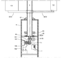
- the vertical rotating shaft 2 is composed of a steel pipe or the like, and is supported by a shaft support base 6 so as to be rotatable in the vertical direction, as shown in FIG.
- the vertical rotation shaft 2 in this embodiment is arranged so that the shaft support base 6 is vertically moved via a ball bearing 63 for reducing rotational friction and a socket 67 for preventing shaft shake during rotation. It is rotatably supported at two locations.
- the vertical rotation shaft 2 and the shaft support base 6 have a pair of magnets 66, 66 so that the same poles (for example, S pole and S pole or N pole and N pole) face each other.
- the vertical rotating shaft 2 can be supported in a state of being floated with respect to the shaft support 6 by the repulsive force between the magnets 66 and 66.
- a neodymium magnet having a strong magnetic force is used as the magnet 66.
- a rotation transmission mechanism 8 for transmitting the rotational force of the vertical rotation shaft 2 to the wind power generation motor 7 is provided as will be described later.
- a chrome plating sheet or the like having a mirror finish with high light reflectivity is affixed to the surface of the vertical rotation shaft 2 so that more sunlight is reflected toward the wind receiving paddle 4 side. ing.
- the support arm 3 supports the wind receiving paddle 4 and is fixed radially from the vertical rotation shaft 2 at equal intervals.
- the three support arms 3 are arranged circumferentially at the upper end and the lower end of the vertical rotating shaft 2, respectively. On the other hand, it is provided at intervals of 120 degrees.
- Each upper support arm 31 is made of a transparent material such as acrylic resin, and the surface of the lower support arm 32 has a mirror finish with high light reflectivity. The sunlight is guided to the wind receiving paddle 4.
- the number of support arms 3 and the circumferential interval are not particularly limited, and are appropriately selected in consideration of the shape and weight of the wind receiving paddle 4 to be supported or the amount of received sunlight. It is what is done.
- the wind receiving paddle 4 receives wind and generates a rotational force with respect to the vertical rotation shaft 2.
- the wind receiving paddle 4 is guided by the concave panel portion 41 that guides the received wind to the front edge side, and the concave panel portion 41. It has a leading edge airflow storage section 42 that receives wind and converts it into rotational force.
- the wind receiving paddle 4 in the present embodiment includes an upper edge airflow stopper 43 and a lower edge airflow stopper 44 for making it difficult for the wind received by the concave panel portion 41 to escape from the vertical direction.
- the wind receiving paddle 4 in the present embodiment has a paddle portion in a paddle type wind power generator having a new shape.
- the concave panel portion 41 is obtained by bending a substantially rectangular panel in plan view as shown in FIGS. Therefore, as shown in FIG. 5, the concave panel portion 41 is supported with the concave surface facing outward, so that it receives wind blown from the outside and easily guides the received wind in the front edge direction. ing.
- the concave panel portion 41 is not limited to a curved shape in a plan view, and may be a straight panel bent in a plan view as shown in FIG.
- the concave panel portion 41 in the present embodiment is formed such that the length from the connecting portion with the support arm 3 to the rear edge portion 46 is longer than that of the support arm 3.
- the area that covers the other concave panel portion 41 that tracks the wind direction surface. Is increasing.
- the concave panel portion 41 in the present embodiment is provided with the solar power generation elements 5 on both the inner and outer surfaces, and the vertical length thereof is the front edge portion in order to increase the area where the solar power generation elements 5 are provided. It is formed in a vertically long shape that is larger than the length connecting 45 and the rear edge 46.
- an amorphous solar cell is used as the solar power generation element 5, but other materials may be used as long as they convert the light energy of sunlight into electric power.
- the solar power generation element 5 is provided in both surfaces of the outer surface 411 and the inner surface 412 of the concave panel part 41, any one surface may be sufficient.
- the material of the concave panel portion 41 is not particularly limited, and is appropriately selected from metal, synthetic resin, and the like.
- the panel itself may be a solar power generation panel, and the film having the solar power generation element 5. Etc. may be attached to the surface.
- the front edge airflow storage part 42 is a part that receives the wind received by the concave panel part 41 at the front edge part 45, and protrudes outward along the front edge part 45 in the rotational direction of the concave panel part 41. And the tip is curved or bent toward the trailing edge.
- the leading edge airflow storage section 42 is made of an aluminum pipe for weight reduction, and as shown in FIGS. 1 and 3, the outer peripheral surface thereof is formed on the concave panel section 41 in plan view.
- An airflow stop hole 49 that is formed in a circular shape or a circular arc shape that is gently continuous along the axis and that is open along the axis is formed.
- leading edge airflow storage part 42 is not limited to what is comprised from a pipe, You may select suitably from a rectangular panel member etc. as shown in FIG.
- the upper edge airflow stopper 43 is provided on the outer surface 411 side of the concave panel 41 along the upper edge 47 of the concave panel 41.
- the upper edge airflow stopper 43 in the present embodiment is provided so as to cover the upper edge 47 of the concave panel portion 41 from the upper edge 47 to the front edge airflow reservoir 42 as shown in FIGS. 1 and 3. It is formed by a transparent acrylic plate. For this reason, while stopping the airflow of the wind received by the concave panel part 41, more sunlight can be permeate
- the lower edge airflow stopper 44 is provided on the outer surface 411 side of the concave panel 41 along the lower edge 48 of the concave panel 41. As shown in FIGS. 1 and 3, the lower edge airflow stopper 44 in the present embodiment is provided so as to cover the lower edge 48 of the concave panel portion 41 from the lower edge 48 to the front edge airflow reservoir 42. It is formed by an acrylic plate. Further, the upper surface of the lower edge airflow stopper 44 is mirror-finished with a high light reflectivity to stop the airflow received by the concave panel 41 and to receive received sunlight of the concave panel 41. The light is reflected toward the outer surface 411.
- the wind receiving paddle 4 has a front edge portion 45 side from an intermediate point between the front edge portion 45 and the rear edge portion 46 of the wind receiving paddle in order to increase the wind receiving area on the rear edge side.
- the support arm 3 is connected to the support arm 3 by a connecting portion. Further, the wind receiving paddle 4 is supported by the support arm 3 in a state where the front edge airflow stopper 42 is inclined inward in order to facilitate the flow of wind from the rear edge 46 toward the front edge 45. ing. In this embodiment, it is inclined at an angle of about 7 ° to 8 ° with respect to the tangent line of the rotating track. This is because if the angle is too small, it is difficult to create a flow of wind, while if the angle is too large, the drag received from the wind is reduced.
- the shaft support 6 includes a pedestal 61 at the lower end and a shaft support 62 provided on the pedestal 61.
- the pedestal 61 in the present embodiment is for fixing the wind power generator 1 in an upright state, and is provided with four holes at the four corners for passing bolts through a rectangular plate.
- the shaft support portion 6 is formed in a cylindrical shape, and as shown in FIG. 2, the wind power generation motor 7 and the rotational force of the vertical rotating shaft 2 are transmitted to the wind power generation motor 7 therein.
- a rotation transmission mechanism 8 that performs power transmission, a solar power generation charger 9 that charges power generated by the solar power generation element 5, an electrode of the solar power generation element 5, and an electrode of the solar power generation charger 9 And an energization mechanism 10 that energizes the current.
- the wind power generation motor 7 is a general power generation motor having a rotating shaft 71 and is fixed inside the shaft support 6 as shown in FIG.
- the rotation transmission mechanism 8 is a mechanism for transmitting the rotational force of the vertical rotation shaft 2 to the rotation shaft 71 of the wind power generation motor 7.
- the motor provided on the rotation shaft 71 of the wind power generation motor 7.
- a side gear 81 and a rotary shaft side gear 82 provided at the lower end of the vertical rotary shaft 2. That is, the rotation transmission mechanism 8 in this embodiment transmits the rotational force of the vertical rotation shaft 2 to the rotation shaft 71 of the wind power generation motor 7 by the motor side gear 81 and the rotation shaft side gear 82 meshing with each other. It is like that.
- the solar power generation charger 9 is a general charger that charges the power generated by the solar power generation elements 5 provided on both surfaces of the curved panel portion 41. As shown in FIG. 6 is installed inside.
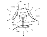
- the energization mechanism 10 is a mechanism for energizing the electrode of the solar power generation element 5 and the electrode of the solar power generation charger 9 without causing a cord or the like to get entangled even when the vertical rotation shaft 2 rotates.
- the element side positive pole gear 101 and the element side negative pole gear 102 fixed to the vertical rotating shaft 2, and the shaft support rotatably fixed to the shaft support base 6. It has a table side plus pole gear 103 and a shaft support table side minus pole gear 104.
- the element-side positive pole gear 101 is a spur gear or the like formed of a material such as a metal having electrical conductivity, and is fixed to the lower end portion of the vertical rotating shaft 2 and is the positive pole of the photovoltaic power generation element 5. 51 is wired to be energized.
- the element-side negative pole gear 102 is a spur gear or the like formed of a material such as a metal having electrical conductivity, similarly to the element-side positive pole gear 101, and is fixed to the lower end portion of the vertical rotating shaft 2. At the same time, the negative electrode 52 of the solar power generation element 5 is connected to be electrically connected.
- the element-side negative pole gear 102 and the element-side positive pole gear 101 are in an electrically insulated state and are not energized with each other.
- the shaft support base side positive pole gear 103 is a gear made of a material such as a metal having electrical conductivity, and is fixed to the shaft support base 6 so as to be rotatable at a position where it is meshed with the element side positive pole gear 101. ing. Therefore, the shaft support base side positive pole gear 103 is engaged with the element side positive pole gear 101 so as to come into contact with each other and to energize each other.
- the shaft support base side positive pole gear 103 is connected to the positive pole 91 of the solar power generation charger 9 provided on the shaft support base 6 so as to be energized.
- the shaft support base side negative pole gear 104 is a gear formed of a material such as a metal having conductivity, similarly to the shaft support base side positive pole gear 103, and the element side negative pole gear with respect to the shaft support base 6. It is rotatably fixed at a position where it engages with 102. Accordingly, the shaft support base side negative pole gear 104 is brought into contact with the element side negative pole gear 102 so as to be energized with each other. Further, the shaft support base side negative pole gear 104 is connected to the negative pole 91 of the solar power generation charger 9 provided on the shaft support base 6 so as to be energized. Further, the shaft support base side negative pole gear 104 and the shaft support base side positive pole gear 103 are in an electrically insulated state and are not energized with each other.
- the wind receiving paddle 4A receives wind mainly by the outer surface 411 of the concave panel portion 41.
- the received wind is guided from the rear edge portion 46 to the front edge portion 45 along the concave panel portion 41 that is curved and inclined with respect to the tangent line of the rotating track.
- the wind receiving paddle 4A in this embodiment since the rear edge side is formed long, many airflows can be guided to the front edge part 45 side.
- the upper edge airflow stopping portion 43 and the lower edge airflow stopping portion 44 stop the airflow in the vertical direction of the wind hitting the outer surface 411 of the concave panel portion 41 and flow the wind toward the front edge portion 45 side. I am guiding you.
- the leading edge airflow storage section 42 in the wind receiving paddle 4A receives the flowing wind and generates a rotational torque centered on the vertical rotating shaft 2 by a reaction to the force. At this time, since the front end portion of the leading edge airflow storage section 42 is curved or bent toward the trailing edge, the airflow guided from the trailing edge can be efficiently converted to rotational torque. This rotational torque is transmitted to the vertical rotation shaft 2 via the support arm 3 and becomes a force for rotating the vertical rotation shaft 2.
- the rotational direction of the wind receiving paddle 4 is a counterclockwise direction in FIG.
- the wind receiving paddle 4B As shown in FIG. 5, the wind is received on the inner surface 412 side of the concave panel portion 41 to generate a force to push in the wind direction. Therefore, the wind receiving paddle 4B rotates the vertical rotating shaft 2 counterclockwise in FIG. 5 by the force pushed by the wind. In this embodiment, since the length from the connection part of the said wind receiving paddle 4A and the said support arm 3 to the said front edge part 45 is short, the wind receiving paddle 4B becomes easy to receive a wind.
- the wind receiving paddle 4C receives a wind opposed to the rotational direction and generates a rotational force in the direction opposite to the rotational direction (counterclockwise) (clockwise).
- the wind receiving paddle 4C is provided at the tip of the support arm 3 so that the outer surface 411 of the concave panel portion 41 faces outward. Therefore, as shown in FIG. 5, the wind receiving paddle 4C has a small projected area with respect to the wind direction, and can reduce the rotational force in the opposite direction (clockwise) generated by the drag received from the wind.
- each wind receiving paddle 4 in the present embodiment is formed in a blade shape, the flow around the leading edge 45 is rectified so as to reduce the stagnation point generated in the leading edge airflow stopper 42. Resistance can be reduced.
- the wind receiving paddle 4A and the wind receiving paddle 4B are likely to generate a counterclockwise rotational moment by the drag.
- the wind receiving paddle 4C is located at a position where the rotation direction and the wind direction are opposed to each other. ing.
- the wind receiving paddle 4 ⁇ / b> A receives wind mainly by the outer surface 411 of the concave panel portion 41.
- the received wind flows from the rear edge 46 to the front edge 45 along the concave panel portion 41.
- the leading edge airflow storage unit 42 receives the flowing wind, and generates counterclockwise rotational torque about the vertical rotation shaft 2 by a reaction to the force.
- the amount of air received by the wind receiving paddle 4A is smaller than the amount received when the outer surface 411 side of the concave panel portion 41 receives the wind in front, but the support arm 3 increases the distance from the vertical rotating shaft 2. Therefore, a strong torque can be generated even with a small air volume.
- the wind receiving paddle 4 ⁇ / b> B has the wind direction facing the inner surface 412 of the concave panel portion 41, so that almost no rotational force is generated in both the positive and negative directions. Therefore, almost no force is acting on the rotation.
- the wind receiving paddle 4C is in a state where the leading edge side is inclined inward with respect to the wind direction. Therefore, the wind is divided into an outer side and an inner side by the leading edge airflow storage unit 42. Then, the inner surface 412 of the wing-shaped concave panel portion 41 and the leading edge airflow storage portion 42 cause a pressure difference between the outer side and the inner side of the wind receiving paddle 4C, thereby generating a so-called inward lift.
- the lift force of the wing is a force that is pulled toward the front edge side and the convex surface side. Therefore, as shown in FIG. 6, a force that rotates the vertical rotation shaft 2 in the positive direction (counterclockwise) Become.
- the vertical length of the wind receiving paddle 4 is formed in a vertically long shape longer than the length connecting the front edge portion 45 and the rear edge portion 46, so that lift is easily generated efficiently. ing.
- the wind receiving paddle 4 ⁇ / b> A winds at a position where the torque to the vertical rotating shaft 2 is easily generated.
- the wind receiving paddle 4C is in a position where the rotation direction and the wind direction are opposed to each other, but the torque is weaker than the torque generated by the wind receiving paddle 4A. Further, in the wind receiving paddle 4C, an inward lift is generated to assist the rotational force.
- the force states shown in FIGS. 5 and 6 are alternately repeated to rotate efficiently. be able to. Therefore, regardless of the direction of the wind that is received, the rotation at the start-up is ensured and the rotation is facilitated during the rotation. For example, starting can be started even with a slight wind of 3 m / s or less.
- the vertical rotating shaft 2 is levitated by a magnet with respect to the shaft support base, the frictional resistance with the shaft support base 6 is small, and it is easier to start.
- the vertical rotating shaft 2 transmits to the rotating shaft 71 of the wind power generation motor 7 via the rotation transmitting mechanism 8 as shown in FIG.
- the wind power generation motor 7 generates electric power by rotating the rotating shaft 71.
- the photovoltaic power generation element 5 provided on the surface of the concave panel portion 41 generates power by receiving sunlight. Further, in the present embodiment, since the upper edge airflow stopper 43 is made transparent, light passes through the upper edge airflow stopper 43 and reaches the outer surface 411 of the concave panel portion 41. Further, the surface of the vertical rotating shaft 2 and the lower edge airflow stopper 44 is mirror-reflected to reflect sunlight to the outer surface 411 and the inner surface 412 of the concave panel 41 so that the amount of light received by the photovoltaic power generation element 5 is increased. It has become.
- the wind turbine generator 1 of the present embodiment can allow the solar power generation element 5 to receive more sunlight without waste, and can efficiently generate power with sunlight.
- the wind receiving paddle 4 vertically long, not only makes it easy to obtain lift, but also the area where the solar power generation element 5 is provided increases and the amount of power generation also increases.
- the electric power generated by the solar power generation element 5 is sent to the solar power generation charger 9 via the energization mechanism 10.
- the element side positive pole gear 101 and the shaft support side positive pole gear 103 can be energized by meshing with each other and contacting each other.
- the element-side negative pole gear 102 and the shaft support base-side negative pole gear 104 can be energized by meshing with and contacting each other. Therefore, as shown in FIG. 2, the positive electrode 51 and the negative electrode 52 of the solar power generation element 5 become a loop-like electric circuit connected to one, and the current generated by the solar power generation element 5 is It is stored in the solar power generation charger 9 through the electric circuit.
- the gears 103 and 104 on the shaft support base 6 are rotatable, they can be rotated together with the gears 101 and 102 on the element side and do not hinder the rotation of the vertical rotating shaft 2. That is, if the solar power generation element 5 and the solar power generation charger 9 are connected by the cord wiring, the cord is wound along with the rotation of the vertical rotation shaft 2, but in the present embodiment, such a problem is caused. Is not generated.
- the structure that is easily subjected to the drag in the rotating direction can increase the certainty of starting at the time of starting and can increase the amount of power generation using wind power and sunlight as energy sources.
- the lift generated on the inner surface 412 of the wind receiving paddle can be a force that boosts the rotation. 4).
- the amount of power generation can be increased together with the lift. 5. Even if the vertical rotation shaft 2 rotates, the cord or the like is not rotated and twisted by using a gear for the contact. 6).
- the outer surface 411 of the wind receiving paddle 4 is supported so as to face outward, the space is saved compared to the case where the longitudinal direction of the wind receiving paddle 4 is arranged along the radial direction. It can be installed easily in empty spaces. 7). It can be comprised with a lightweight member and the rotation resistance by dead weight can be reduced.
- the wind power generator according to the present invention is not limited to the above-described embodiment, and can be changed as appropriate.
- each gear in the energization mechanism 10 and each gear in the rotation transmission mechanism 8 are configured separately, but a common gear may be used.
- a plurality of wind receiving paddles 4 may be connected vertically.
- a signboard 64 for displaying a corporate advertisement or the like may be installed at the upper end of the vertical rotating shaft 2. Thereby, not only can the electric power required for the illumination 65 of the signboard 64 be sufficiently supplied, but it is also possible to increase profits by causing the electric power company to purchase surplus electric power.
Landscapes
- Engineering & Computer Science (AREA)
- Chemical & Material Sciences (AREA)
- Life Sciences & Earth Sciences (AREA)
- Sustainable Development (AREA)
- Sustainable Energy (AREA)
- Combustion & Propulsion (AREA)
- Mechanical Engineering (AREA)
- General Engineering & Computer Science (AREA)
- Power Engineering (AREA)
- Fluid Mechanics (AREA)
- Physics & Mathematics (AREA)
- Wind Motors (AREA)
- Photovoltaic Devices (AREA)
Abstract
Description
1.回転方向の抗力を受けやすい構造によって起動時における始動の確実性を高めるとともに、風力および太陽光をエネルギー源とする発電量を増加することができる。
2.前縁気流貯留部42に風を集中させるとともに、風向きに対して投影面積を減らすことで抵抗を減らし、回転しやすくすることができる。
3.受風パドルの内面412に生じる揚力により、回転を後押しする力とすることができる。
4.受風パドル4を大型化することにより、揚力とともに発電量を増やすことができる。
5.垂直回転軸2が回転しても、接点にギヤを用いることにより、コード等が回転してねじ切れることがない。
6.受風パドル4の外面411が外側を向くように支持するため、受風パドル4の長手方向を放射方向に沿って配置する場合と比較して省スペース化され、オフィスビルの屋上や建物の傍の空きスペース等にも手軽に設置することができる。
7.軽量な部材で構成することができ、自重による回転抵抗を低減することができる。
2 垂直回転軸
3 支持アーム
4 受風パドル
5 太陽光発電素子
6 軸支持台
7 風力発電用モータ
8 回転伝達機構
9 太陽光発電用充電器
10 通電機構
31 上端支持アーム
32 下端支持アーム
41 凹状パネル部
42 前縁気流貯留部
43 上縁気流止め部
44 下縁気流止め部
45 前縁部
46 後縁部
47 上縁部
48 下縁部
49 気流止め穴
51 プラス極
52 マイナス極
61 台座部
62 軸支持部
63 ボールベアリング
64 看板
65 照明
66 磁石
67 ソケット
71 回転軸
81 モータ側ギヤ
82 回転軸側ギヤ
91 プラス極
92 マイナス極
101 素子側プラス極ギヤ
102 素子側マイナス極ギヤ
103 軸支持台側プラス極ギヤ
104 軸支持台側マイナス極ギヤ
411 外面
412 内面
Claims (6)
- 風力発電用モータに回転力を伝える垂直回転軸と、この垂直回転軸から放射状に等間隔で設けられる複数の支持アームと、各々の前記支持アームの先端に接続された受風パドルとを有する風力発電装置であって、
前記受風パドルが平面視で外面側を凹状に湾曲または屈曲してなる凹状パネル部と、この凹状パネル部の回転方向における前縁部に沿って外面側に突出しかつその先端部が後縁部側に湾曲または屈曲してなる前縁気流貯留部が設けられている風力発電装置。 - 前記受風パドルと前記支持アームとが前記受風パドルの前縁部と後縁部との中間点より前記前縁部側で接続されている、請求項1に記載の風力発電装置。
- 前記受風パドルにおける前記支持アームとの接続部から前記後縁部までの長さが前記支持アームより長く形成されている、請求項1または請求項2に記載の風力発電装置。
- 前記受風パドルが、前記凹状パネル部の上縁部および下縁部に沿って前記外面側に設けられた上縁気流止め部および下縁気流止め部を備えている、請求項1から請求項3のいずれかに記載の風力発電装置。
- 前記垂直回転軸が磁力の反発力により浮遊状態で回転自在に支持されている請求項1から請求項4のいずれかに記載の風力発電装置。
- 前記受風パドルは、上下の縦長さが前縁部と後縁部とを結ぶ長さよりも大きい縦長形状に形成されているとともに、前記凹状パネル部の内外両面またはいずれか一面に太陽光発電素子が設けられ、前記太陽光発電素子の電極と、前記垂直回転軸を支持する軸支持台に設けられた電極との通電を行う通電機構を有しており、
前記通電機構が、前記垂直回転軸に固定されているとともに前記太陽光発電素子のプラス極と通電可能に接続されている素子側プラス極ギヤと、
前記垂直回転軸に固定されているとともに前記太陽光発電素子のマイナス極と通電可能に接続されている素子側マイナス極ギヤと、
前記軸支持台に回転可能に固定され、かつ前記素子側プラス極ギヤと噛み合わされているとともに前記軸支持台のプラス極と通電可能に接続されている軸支持台側プラス極ギヤと、
前記軸支持台に回転可能に固定され、かつ前記素子側マイナス極ギヤと噛み合わされているとともに前記軸支持台のマイナス極と通電可能に接続されている軸支持台側マイナス極ギヤと
を備えている請求項1から請求項5のいずれかに記載の風力発電装置。
Priority Applications (6)
| Application Number | Priority Date | Filing Date | Title |
|---|---|---|---|
| JP2015542642A JP5972478B2 (ja) | 2013-10-18 | 2014-10-15 | 風力発電装置 |
| US15/029,180 US10451041B2 (en) | 2013-10-18 | 2014-10-15 | Wind power generation device |
| HK16110559.4A HK1222424A1 (zh) | 2013-10-18 | 2014-10-15 | 风力发电装置 |
| EP14854038.8A EP3059443A4 (en) | 2013-10-18 | 2014-10-15 | Wind power generation device |
| KR1020167012219A KR20160073981A (ko) | 2013-10-18 | 2014-10-15 | 풍력발전장치 |
| CN201480057288.4A CN105765215B (zh) | 2013-10-18 | 2014-10-15 | 风力发电装置 |
Applications Claiming Priority (2)
| Application Number | Priority Date | Filing Date | Title |
|---|---|---|---|
| JP2013216877 | 2013-10-18 | ||
| JP2013-216877 | 2013-10-18 |
Publications (1)
| Publication Number | Publication Date |
|---|---|
| WO2015056722A1 true WO2015056722A1 (ja) | 2015-04-23 |
Family
ID=52828164
Family Applications (1)
| Application Number | Title | Priority Date | Filing Date |
|---|---|---|---|
| PCT/JP2014/077469 Ceased WO2015056722A1 (ja) | 2013-10-18 | 2014-10-15 | 風力発電装置 |
Country Status (7)
| Country | Link |
|---|---|
| US (1) | US10451041B2 (ja) |
| EP (1) | EP3059443A4 (ja) |
| JP (1) | JP5972478B2 (ja) |
| KR (1) | KR20160073981A (ja) |
| CN (1) | CN105765215B (ja) |
| HK (1) | HK1222424A1 (ja) |
| WO (1) | WO2015056722A1 (ja) |
Cited By (4)
| Publication number | Priority date | Publication date | Assignee | Title |
|---|---|---|---|---|
| JP2020064765A (ja) * | 2018-10-18 | 2020-04-23 | 株式会社アイエール電器 | ソーラー屋外灯 |
| JP2021535624A (ja) * | 2018-08-24 | 2021-12-16 | ソリバス・リミテッドSolivus Limited | 太陽光発電装置 |
| CN114857712A (zh) * | 2022-07-05 | 2022-08-05 | 航天建设集团深圳有限公司 | 一种具有透光与空气净化功能的建筑结构 |
| US20260028964A1 (en) * | 2022-07-11 | 2026-01-29 | Phos Global Energy Solutions, Inc. | Solar windmill for joint power generation |
Families Citing this family (19)
| Publication number | Priority date | Publication date | Assignee | Title |
|---|---|---|---|---|
| GR20160100640A (el) * | 2016-12-23 | 2018-10-12 | Αντωνιος Γεωργιου Χατζηκοντος | Ανεμογεννητρια καθετου αξονα με κινηση απο αερα και ηλιο |
| DE102017106434A1 (de) * | 2017-03-24 | 2018-09-27 | Athanasios Dafnis | Schwimmende offshore Windkraftanlage mit einem vertikalen Rotor und Windpark in Modularbauweise umfassend mehrere solcher Windkraftanlagen |
| US20200208606A1 (en) * | 2017-09-04 | 2020-07-02 | Toshimitsu YAMAZAWA | Wind power generation device |
| KR20190085599A (ko) | 2018-01-11 | 2019-07-19 | 이태관 | 풍력 발전 장치 |
| CN108110883A (zh) * | 2018-01-17 | 2018-06-01 | 安徽中骄智能科技有限公司 | 一种室外用无人机充电平台 |
| IT201800003987A1 (it) * | 2018-03-27 | 2019-09-27 | Ianni Giuseppe Di | Impianto fotovoltaico-eolico a profilo modulare variabile mediante cuscinetto a levitazione magnetica ad inversione di marcia per la produzione di energia elettrica |
| KR102183450B1 (ko) | 2018-09-18 | 2020-11-27 | 이태관 | 풍력 발전 장치 |
| CA3186395A1 (en) * | 2019-07-27 | 2021-02-04 | Siva Raghuram Prasad Chennupati | Universal propeller, operating method and favoured use |
| KR20210055181A (ko) | 2019-11-07 | 2021-05-17 | 아보들 아지즈 모하마드 | 음식 배달 서비스를 제공하기 위한 컴퓨터 프로그램 |
| CN111262511A (zh) * | 2019-12-28 | 2020-06-09 | 山东东山新驿煤矿有限公司 | 一种光伏发电旋转跟踪发电系统及方法 |
| FR3120487A1 (fr) * | 2021-03-08 | 2022-09-09 | Frncois Marceau | Éolienne solaire |
| CN114465560A (zh) * | 2022-03-30 | 2022-05-10 | 深圳市人居大健康科技有限公司 | 一种多功能光伏发电及农光互补装置 |
| JP2023152504A (ja) * | 2022-04-04 | 2023-10-17 | 孝俊 高谷 | 風力発電装置 |
| CN114954546A (zh) * | 2022-07-04 | 2022-08-30 | 中南大学 | 用于控制高速列车升力翼的方法、计算机设备和存储介质 |
| CN115214729B (zh) * | 2022-08-23 | 2023-09-19 | 中南大学 | 一种高速列车抗横风翻转伸缩翼 |
| CN115158377B (zh) * | 2022-08-23 | 2023-11-28 | 中南大学 | 一种高速列车抗横风方法及可翻转车翼 |
| CN115158376B (zh) * | 2022-08-23 | 2023-09-19 | 中南大学 | 一种高速列车抗横风竖向伸缩翼及控制方法 |
| CN115214730B (zh) * | 2022-08-23 | 2023-09-19 | 中南大学 | 一种高速列车抗横风方法及车翼 |
| CN118137936B (zh) * | 2024-05-07 | 2024-07-19 | 湖南国奥电力设备有限公司 | 一种风光储能装置及杆塔 |
Citations (8)
| Publication number | Priority date | Publication date | Assignee | Title |
|---|---|---|---|---|
| JPH06167269A (ja) * | 1992-12-01 | 1994-06-14 | C R C Sogo Kenkyusho:Kk | 太陽電池付き風車 |
| JPH11173257A (ja) * | 1997-12-05 | 1999-06-29 | Enesaabu Kk | 自然エネルギーの総合利用システム |
| JP2001132617A (ja) * | 1999-11-01 | 2001-05-18 | Masaharu Miyake | 風力発電装置 |
| JP2003218190A (ja) * | 2002-01-18 | 2003-07-31 | Dainippon Screen Mfg Co Ltd | 回転接続装置およびそれを用いた基板処理装置 |
| JP3451085B1 (ja) | 2002-09-20 | 2003-09-29 | 常夫 野口 | 風力発電用の風車 |
| JP2006090293A (ja) * | 2004-09-22 | 2006-04-06 | Katsuumi Yoshimi | 風車 |
| JP2011112013A (ja) * | 2009-11-30 | 2011-06-09 | Panasonic Corp | 風力発電装置 |
| JP2013534592A (ja) * | 2010-07-16 | 2013-09-05 | テルビット フー イウォナ ヤノフスカ | 垂直軸風車 |
Family Cites Families (11)
| Publication number | Priority date | Publication date | Assignee | Title |
|---|---|---|---|---|
| WO2007064155A1 (en) * | 2005-11-30 | 2007-06-07 | Geumpoong Energy | Aerogenerator |
| US20090160196A1 (en) * | 2007-12-24 | 2009-06-25 | James Metzloff | Wind driven electric generator having vertical rotational axis |
| CN101260863A (zh) * | 2008-04-14 | 2008-09-10 | 王誉燕 | 一种主翼随风向变动转角的风车叶片 |
| JP2011099330A (ja) | 2009-11-04 | 2011-05-19 | Noai Kk | 道路に於ける電気設備に対する電力供給方法と装置 |
| US8550786B2 (en) * | 2009-12-11 | 2013-10-08 | Peter Janiuk | Vertical axis wind turbine with self-starting capabilities |
| JP5498775B2 (ja) | 2009-12-25 | 2014-05-21 | 株式会社Wind−Smile | 垂直軸風車 |
| CN101839219A (zh) * | 2010-04-08 | 2010-09-22 | 南京永乐光电科技有限公司 | 垂直轴风力发电机翼形叶片及翼形垂直轴风力发电机 |
| US7988413B2 (en) * | 2010-04-23 | 2011-08-02 | Eastern Wind Power | Vertical axis wind turbine |
| US8905704B2 (en) * | 2010-11-15 | 2014-12-09 | Sauer Energy, Inc. | Wind sail turbine |
| KR101169546B1 (ko) * | 2011-02-14 | 2012-07-27 | 전북대학교산학협력단 | 하이브리드형 발전시스템 |
| DE102011118844B3 (de) * | 2011-11-18 | 2013-04-18 | Sandrah Kreye | Vertikalwindturbine und Rotorblatt hierfür |
-
2014
- 2014-10-15 JP JP2015542642A patent/JP5972478B2/ja not_active Expired - Fee Related
- 2014-10-15 EP EP14854038.8A patent/EP3059443A4/en not_active Withdrawn
- 2014-10-15 HK HK16110559.4A patent/HK1222424A1/zh unknown
- 2014-10-15 WO PCT/JP2014/077469 patent/WO2015056722A1/ja not_active Ceased
- 2014-10-15 CN CN201480057288.4A patent/CN105765215B/zh not_active Expired - Fee Related
- 2014-10-15 US US15/029,180 patent/US10451041B2/en active Active
- 2014-10-15 KR KR1020167012219A patent/KR20160073981A/ko not_active Withdrawn
Patent Citations (8)
| Publication number | Priority date | Publication date | Assignee | Title |
|---|---|---|---|---|
| JPH06167269A (ja) * | 1992-12-01 | 1994-06-14 | C R C Sogo Kenkyusho:Kk | 太陽電池付き風車 |
| JPH11173257A (ja) * | 1997-12-05 | 1999-06-29 | Enesaabu Kk | 自然エネルギーの総合利用システム |
| JP2001132617A (ja) * | 1999-11-01 | 2001-05-18 | Masaharu Miyake | 風力発電装置 |
| JP2003218190A (ja) * | 2002-01-18 | 2003-07-31 | Dainippon Screen Mfg Co Ltd | 回転接続装置およびそれを用いた基板処理装置 |
| JP3451085B1 (ja) | 2002-09-20 | 2003-09-29 | 常夫 野口 | 風力発電用の風車 |
| JP2006090293A (ja) * | 2004-09-22 | 2006-04-06 | Katsuumi Yoshimi | 風車 |
| JP2011112013A (ja) * | 2009-11-30 | 2011-06-09 | Panasonic Corp | 風力発電装置 |
| JP2013534592A (ja) * | 2010-07-16 | 2013-09-05 | テルビット フー イウォナ ヤノフスカ | 垂直軸風車 |
Non-Patent Citations (1)
| Title |
|---|
| See also references of EP3059443A4 * |
Cited By (5)
| Publication number | Priority date | Publication date | Assignee | Title |
|---|---|---|---|---|
| JP2021535624A (ja) * | 2018-08-24 | 2021-12-16 | ソリバス・リミテッドSolivus Limited | 太陽光発電装置 |
| US11705858B2 (en) | 2018-08-24 | 2023-07-18 | Solivus Limited | Solar electrical generator |
| JP2020064765A (ja) * | 2018-10-18 | 2020-04-23 | 株式会社アイエール電器 | ソーラー屋外灯 |
| CN114857712A (zh) * | 2022-07-05 | 2022-08-05 | 航天建设集团深圳有限公司 | 一种具有透光与空气净化功能的建筑结构 |
| US20260028964A1 (en) * | 2022-07-11 | 2026-01-29 | Phos Global Energy Solutions, Inc. | Solar windmill for joint power generation |
Also Published As
| Publication number | Publication date |
|---|---|
| US10451041B2 (en) | 2019-10-22 |
| US20160258420A1 (en) | 2016-09-08 |
| EP3059443A1 (en) | 2016-08-24 |
| CN105765215B (zh) | 2021-09-03 |
| JPWO2015056722A1 (ja) | 2017-03-09 |
| EP3059443A4 (en) | 2017-06-28 |
| HK1222424A1 (zh) | 2017-06-30 |
| CN105765215A (zh) | 2016-07-13 |
| KR20160073981A (ko) | 2016-06-27 |
| JP5972478B2 (ja) | 2016-08-17 |
Similar Documents
| Publication | Publication Date | Title |
|---|---|---|
| JP5972478B2 (ja) | 風力発電装置 | |
| JP4041838B2 (ja) | 風力発電用の風車及び風力発電装置 | |
| US9284944B2 (en) | Vertical shaft type darius windmill | |
| US7303369B2 (en) | Magnetic vertical axis wind turbine | |
| US20090191057A1 (en) | Multi-Axis Wind Turbine With Power Concentrator Sail | |
| WO2019230655A1 (ja) | 垂直軸風車およびこれを備えた風力発電装置と照明設備 | |
| CN110770435B (zh) | 帆装置 | |
| CN204627867U (zh) | 一种海上发电装置 | |
| JPWO2019045114A1 (ja) | 風力発電装置 | |
| TWM462792U (zh) | 垂直軸式風力發電機 | |
| JP3187508U (ja) | 垂直軸式風力発電機 | |
| CN203230525U (zh) | 海洋能发电装置及其框架 | |
| CN102582811B (zh) | 转子集成式风电帆船及发电方法 | |
| JP5941200B1 (ja) | 多重螺旋式構造体 | |
| CN204511768U (zh) | 风力发电扇叶结构 | |
| KR101079773B1 (ko) | 고리형 날개가 구비된 풍력발전장치 | |
| US11346321B2 (en) | Windmill design effective at lower wind speeds | |
| CN107676225A (zh) | 一种小型非对称翼直叶片垂直轴风力发电机 | |
| CN207598421U (zh) | 一种小型非对称翼直叶片垂直轴风力发电机 | |
| KR101642284B1 (ko) | 강관 축을 이용한 나무 형태의 풍력발전기 | |
| TWI299769B (en) | Magnus type wind power generation system | |
| WO2012055378A1 (es) | Rotor de turbina eólica | |
| KR101256005B1 (ko) | 풍력발전장치 | |
| CN202645842U (zh) | 风力海浪驱动叶轮 | |
| JP2020016167A (ja) | マグナス式推力発生装置、前記マグナス式推力発生装置を用いた風力回転装置、水力回転装置、潮力回転装置、ならびに前記マグナス式推力発生装置を用いた風力発電機、水力発電機、潮力発電機 |
Legal Events
| Date | Code | Title | Description |
|---|---|---|---|
| 121 | Ep: the epo has been informed by wipo that ep was designated in this application |
Ref document number: 14854038 Country of ref document: EP Kind code of ref document: A1 |
|
| DPE1 | Request for preliminary examination filed after expiration of 19th month from priority date (pct application filed from 20040101) | ||
| ENP | Entry into the national phase |
Ref document number: 2015542642 Country of ref document: JP Kind code of ref document: A |
|
| WWE | Wipo information: entry into national phase |
Ref document number: 15029180 Country of ref document: US |
|
| NENP | Non-entry into the national phase |
Ref country code: DE |
|
| REEP | Request for entry into the european phase |
Ref document number: 2014854038 Country of ref document: EP |
|
| WWE | Wipo information: entry into national phase |
Ref document number: 2014854038 Country of ref document: EP |
|
| ENP | Entry into the national phase |
Ref document number: 20167012219 Country of ref document: KR Kind code of ref document: A |