WO2015059852A1 - 表示装置およびその制御方法 - Google Patents
表示装置およびその制御方法 Download PDFInfo
- Publication number
- WO2015059852A1 WO2015059852A1 PCT/JP2014/003999 JP2014003999W WO2015059852A1 WO 2015059852 A1 WO2015059852 A1 WO 2015059852A1 JP 2014003999 W JP2014003999 W JP 2014003999W WO 2015059852 A1 WO2015059852 A1 WO 2015059852A1
- Authority
- WO
- WIPO (PCT)
- Prior art keywords
- signal
- period
- visible light
- backlight
- light communication
- Prior art date
- Legal status (The legal status is an assumption and is not a legal conclusion. Google has not performed a legal analysis and makes no representation as to the accuracy of the status listed.)
- Ceased
Links
Images
















Classifications
-
- G—PHYSICS
- G09—EDUCATION; CRYPTOGRAPHY; DISPLAY; ADVERTISING; SEALS
- G09G—ARRANGEMENTS OR CIRCUITS FOR CONTROL OF INDICATING DEVICES USING STATIC MEANS TO PRESENT VARIABLE INFORMATION
- G09G3/00—Control arrangements or circuits, of interest only in connection with visual indicators other than cathode-ray tubes
- G09G3/20—Control arrangements or circuits, of interest only in connection with visual indicators other than cathode-ray tubes for presentation of an assembly of a number of characters, e.g. a page, by composing the assembly by combination of individual elements arranged in a matrix no fixed position being assigned to or needed to be assigned to the individual characters or partial characters
- G09G3/34—Control arrangements or circuits, of interest only in connection with visual indicators other than cathode-ray tubes for presentation of an assembly of a number of characters, e.g. a page, by composing the assembly by combination of individual elements arranged in a matrix no fixed position being assigned to or needed to be assigned to the individual characters or partial characters by control of light from an independent source
- G09G3/3406—Control of illumination source
-
- H—ELECTRICITY
- H04—ELECTRIC COMMUNICATION TECHNIQUE
- H04B—TRANSMISSION
- H04B10/00—Transmission systems employing electromagnetic waves other than radio-waves, e.g. infrared, visible or ultraviolet light, or employing corpuscular radiation, e.g. quantum communication
- H04B10/11—Arrangements specific to free-space transmission, i.e. transmission through air or vacuum
- H04B10/114—Indoor or close-range type systems
- H04B10/116—Visible light communication
-
- G—PHYSICS
- G09—EDUCATION; CRYPTOGRAPHY; DISPLAY; ADVERTISING; SEALS
- G09G—ARRANGEMENTS OR CIRCUITS FOR CONTROL OF INDICATING DEVICES USING STATIC MEANS TO PRESENT VARIABLE INFORMATION
- G09G3/00—Control arrangements or circuits, of interest only in connection with visual indicators other than cathode-ray tubes
- G09G3/20—Control arrangements or circuits, of interest only in connection with visual indicators other than cathode-ray tubes for presentation of an assembly of a number of characters, e.g. a page, by composing the assembly by combination of individual elements arranged in a matrix no fixed position being assigned to or needed to be assigned to the individual characters or partial characters
- G09G3/34—Control arrangements or circuits, of interest only in connection with visual indicators other than cathode-ray tubes for presentation of an assembly of a number of characters, e.g. a page, by composing the assembly by combination of individual elements arranged in a matrix no fixed position being assigned to or needed to be assigned to the individual characters or partial characters by control of light from an independent source
- G09G3/3406—Control of illumination source
- G09G3/342—Control of illumination source using several illumination sources separately controlled corresponding to different display panel areas, e.g. along one dimension such as lines
-
- G—PHYSICS
- G09—EDUCATION; CRYPTOGRAPHY; DISPLAY; ADVERTISING; SEALS
- G09G—ARRANGEMENTS OR CIRCUITS FOR CONTROL OF INDICATING DEVICES USING STATIC MEANS TO PRESENT VARIABLE INFORMATION
- G09G2310/00—Command of the display device
- G09G2310/02—Addressing, scanning or driving the display screen or processing steps related thereto
- G09G2310/024—Scrolling of light from the illumination source over the display in combination with the scanning of the display screen
-
- G—PHYSICS
- G09—EDUCATION; CRYPTOGRAPHY; DISPLAY; ADVERTISING; SEALS
- G09G—ARRANGEMENTS OR CIRCUITS FOR CONTROL OF INDICATING DEVICES USING STATIC MEANS TO PRESENT VARIABLE INFORMATION
- G09G2310/00—Command of the display device
- G09G2310/08—Details of timing specific for flat panels, other than clock recovery
-
- G—PHYSICS
- G09—EDUCATION; CRYPTOGRAPHY; DISPLAY; ADVERTISING; SEALS
- G09G—ARRANGEMENTS OR CIRCUITS FOR CONTROL OF INDICATING DEVICES USING STATIC MEANS TO PRESENT VARIABLE INFORMATION
- G09G2320/00—Control of display operating conditions
- G09G2320/06—Adjustment of display parameters
- G09G2320/0613—The adjustment depending on the type of the information to be displayed
- G09G2320/062—Adjustment of illumination source parameters
-
- G—PHYSICS
- G09—EDUCATION; CRYPTOGRAPHY; DISPLAY; ADVERTISING; SEALS
- G09G—ARRANGEMENTS OR CIRCUITS FOR CONTROL OF INDICATING DEVICES USING STATIC MEANS TO PRESENT VARIABLE INFORMATION
- G09G2320/00—Control of display operating conditions
- G09G2320/06—Adjustment of display parameters
- G09G2320/0626—Adjustment of display parameters for control of overall brightness
- G09G2320/064—Adjustment of display parameters for control of overall brightness by time modulation of the brightness of the illumination source
-
- G—PHYSICS
- G09—EDUCATION; CRYPTOGRAPHY; DISPLAY; ADVERTISING; SEALS
- G09G—ARRANGEMENTS OR CIRCUITS FOR CONTROL OF INDICATING DEVICES USING STATIC MEANS TO PRESENT VARIABLE INFORMATION
- G09G2320/00—Control of display operating conditions
- G09G2320/08—Arrangements within a display terminal for setting, manually or automatically, display parameters of the display terminal
-
- G—PHYSICS
- G09—EDUCATION; CRYPTOGRAPHY; DISPLAY; ADVERTISING; SEALS
- G09G—ARRANGEMENTS OR CIRCUITS FOR CONTROL OF INDICATING DEVICES USING STATIC MEANS TO PRESENT VARIABLE INFORMATION
- G09G2360/00—Aspects of the architecture of display systems
- G09G2360/16—Calculation or use of calculated indices related to luminance levels in display data
Definitions
- the present disclosure relates to a display device capable of outputting a visible light communication signal and a control method thereof.
- Patent Documents 1 and 2 disclose a communication technique using visible light.
- Patent Documents 1 and 2 disclose a communication technique that performs display by superimposing communication information by visible light on a normal video display in a video display device including a display, a projector, and the like.
- the present disclosure provides a display device capable of outputting a visible light communication signal without greatly degrading the image quality of a display image, and reducing a reception error of the output visible light communication signal, and a control method thereof.
- a display device is a display device that is capable of outputting a visible light communication signal, and displays a video on a display panel having a display surface for displaying video, and the display panel based on the video signal.
- a display control unit for controlling the display panel, a backlight having a light emitting surface for illuminating the display surface of the display panel from the back, and a backlight control generated based on the video signal for the visible light communication signal.
- a signal processing unit to be superimposed on the signal, and a light emission surface of the backlight is divided into a plurality of regions, and the light emission is controlled in each of the plurality of regions according to a backlight control signal output by the signal processing unit; and
- a backlight control unit that provides periods for controlling the turning off at different timings in each of the plurality of regions, and the signal processing unit When superimposing the visible light communication signal to the backlight control signal, for the signal indicating the extinction of the backlight of the backlight control signal, it does not overlap the visible light communication signal.
- the display device can output a visible light communication signal without greatly degrading the image quality of a display image, and can reduce reception errors of the output visible light communication signal.
- FIG. 1 is a schematic diagram illustrating an example of a visible light communication system according to the first embodiment.
- FIG. 2 is a block diagram of an example of a schematic configuration of the display device according to the first embodiment.
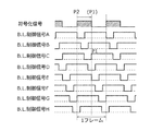
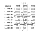
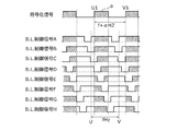
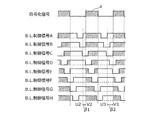
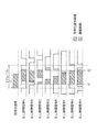
- FIG. 3A is a diagram illustrating B.3 according to Example 1 of the first embodiment. It is a figure which shows an example of the state before superimposing a visible light communication signal on L control signal.
- FIG. 3B is a diagram illustrating B.3 according to Example 1 of the first embodiment. It is a figure which shows an example of the state which superimposed the visible light communication signal on L control signal.
- FIG. 4 is a timing chart for explaining the first method in example 2 of the first embodiment.
- FIG. 5 is a timing chart for explaining the first method in example 2 of the first embodiment.
- FIG. 4 is a timing chart for explaining the first method in example 2 of the first embodiment.
- FIG. 6A is a timing chart for explaining a second method in the second example of the first embodiment.
- FIG. 6B is a timing chart for explaining a second method in the second example of the first embodiment.
- FIG. 6C is a timing chart for explaining a second method in the second example of the first embodiment.
- FIG. 6D is a timing chart for explaining a second method in the second example of the first embodiment.
- FIG. 7A is a timing chart for explaining a second method in the second example of the first embodiment.
- FIG. 7B is a timing chart for explaining a second method in the second example of the first embodiment.
- FIG. 7C is a timing chart for explaining the second method in the second example of the first embodiment.
- FIG. 7D is a timing chart for explaining a second method in the second example of the first embodiment.
- FIG. 7A is a timing chart for explaining a second method in the second example of the first embodiment.
- FIG. 7B is a timing chart for explaining a second method in the second example of the
- FIG. 8 is a diagram illustrating B.3 in Example 3 of the first embodiment. It is a timing chart for demonstrating the method of superimposing a visible light communication signal on L control signal.
- FIG. 9 is a flowchart for explaining the operation of the second processing unit in the second embodiment.
- FIG. 10A is a diagram illustrating B.3 in the second embodiment. It is a figure for demonstrating the specific method of superimposing an encoding signal on L control signal.
- FIG. 10B shows the B.D. It is a figure for demonstrating the specific method of superimposing an encoding signal on L control signal.
- FIG. 10C is a diagram illustrating B.3 in the second embodiment. It is a figure for demonstrating the specific method of superimposing an encoding signal on L control signal.
- FIG. 10A is a diagram illustrating B.3 in the second embodiment. It is a figure for demonstrating the specific method of superimposing an encoding signal on L control signal.
- FIG. 10B shows the B.D.
- FIG. 10D shows the B.D. It is a figure for demonstrating the specific method of superimposing an encoding signal on L control signal.
- FIG. 11 is a diagram illustrating B.3 in the second embodiment. It is a figure for demonstrating another specific method of superimposing an encoding signal on L control signal.
- FIG. 12 is a flowchart for explaining the operation of the second processing unit in the third embodiment.
- FIG. 13 is a timing chart illustrating an example of area group division according to the third embodiment.
- FIG. 14 is a timing chart showing another example of area group division according to the third embodiment.
- FIG. 15 is a timing chart showing another example of area group division according to the third exemplary embodiment.
- FIG. 16 is a flowchart for explaining the operation of the second processing unit in the fourth embodiment.
- FIG. 17A is a diagram illustrating B.3 in the fourth embodiment. It is a figure for demonstrating the relationship of the phase of L control signal and a visible light communication signal.
- FIG. 17B is a diagram illustrating B.3 in the fourth embodiment. It is a figure for demonstrating the relationship of the phase of L control signal and a visible light communication signal.
- FIG. 18A is a timing chart for explaining the operation of the second processing unit in the fourth embodiment.
- FIG. 18B is a timing chart for explaining the operation of the second processing unit in the fourth embodiment.
- FIG. 18C is a timing chart for explaining the operation of the second processing unit in the fourth embodiment.
- FIG. 19A is a timing chart for explaining the operation of the second processing unit in the fifth embodiment.
- FIG. 19B is a timing chart for explaining the operation of the second processing unit in the fifth embodiment.
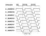
- FIG. 20 is a timing chart illustrating backlight control when local dimming is applied according to the sixth embodiment.
- FIG. 21 is a flowchart for explaining an example of the operation of the second processing unit in the sixth embodiment.
- FIG. 22 is a timing chart for explaining an example of the operation of the second processing unit in the sixth embodiment.
- FIG. 23 is a flowchart for explaining an example of the operation of the second processing unit in the sixth embodiment.
- FIG. 24 is a timing chart for explaining an example of the operation of the second processing unit in the sixth embodiment.
- FIG. 25 is a timing chart for explaining an example of the operation of the second processing unit in the sixth embodiment.
- the backlight scan is a backlight control method that improves the slow response speed of the liquid crystal and the motion blur due to the hold type.
- the display screen is divided into several areas (backlight areas).
- the light emission of the backlight is controlled so that it is sequentially turned on periodically every time.
- the backlight scan is a control method in which a backlight extinction period is provided and the timing of the extinction period (blanking period) that is periodically performed in each backlight region is different. In general, the blanking period is often controlled so as to match the liquid crystal scanning timing.
- Patent Document 1 in visible light communication, a method of superimposing a visible light communication signal by blinking a backlight is used. Therefore, the visible light communication signal cannot be transmitted during the backlight turn-off time, and this stop period causes a signal transmission error. There wasn't.
- the present disclosure provides a display device that can output a visible light communication signal without greatly degrading the image quality of a display image, and reduce reception errors of the output visible light communication signal.
- FIG. 1 is a schematic diagram illustrating an example of a visible light communication system according to the first embodiment.
- a visible light communication system 10 illustrated in FIG. 1 includes a display device 100 and a smartphone 200.
- the display device 100 is a television, for example, and can display an image on the display surface 110.
- the display device 100 can also superimpose a visible light communication signal on the display surface 110.
- the smartphone 200 is an example of an electronic device that receives a visible light communication signal, and can receive the visible light communication signal transmitted from the display device 100. Thereby, the user of the smartphone 200 can receive information related to the video displayed on the display device 100.
- the display device 100 is described by taking a monitor that displays an image such as a television or a display as an example, but is not limited thereto.
- the display device 100 may be a device that projects an image like a projector.
- the smart phone 200 is mentioned as an example as an electronic device which receives the visible light communication signal which the display apparatus 100 output, if it is an electronic device which can receive a visible light communication signal, it will not be restricted to a smart phone.
- the electronic device may be a receiving device compliant with JEITA-CP1222.
- this electronic device is not limited to a smartphone but may be a general mobile terminal.
- the electronic device may receive the visible light communication signal and obtain the information by decoding the received visible light communication signal.
- the information transmission method for transmitting the visible light communication signal may be based on a standard such as JEITA-CP-1223, which is currently being developed into an international standard, or IEEE-P802.15 that has been created.
- the electronic device may be configured using a receiving device that supports these standards.
- FIG. 2 is a block diagram of an example of a schematic configuration of the display device according to the first embodiment.
- a display device 100 illustrated in FIG. 2 is a display device that can output a visible light communication signal, and includes a first input unit 120, a first processing unit 130, a first control unit 140, and a display panel 150.
- the first input unit 120 receives a video signal related to a video displayed on the display panel 150.
- the video signal is sent from the first input unit 120 via, for example, a broadcast radio wave, a video recorder / player, a PC, or the like through an antenna cable, video signal line, composite cable, HDMI (registered trademark) cable, PJLink cable, LAN cable, or the like. Is input.
- the video signal may be stored in various recording media using a video recorder or a player.
- the first processing unit 130 receives a video signal from the first input unit 120.
- the first processing unit 130 performs general image processing such as image quality processing on the video signal.
- the first processing unit 130 transmits the video signal subjected to the image processing to the first control unit 140.
- the first processing unit 130 transmits information indicating the size of a subframe or video signal, display timing, brightness, and the like to the first control unit 140 and the second processing unit 170.
- the first processing unit 130 may output a duty ratio calculated based on the video signal and a backlight control signal (hereinafter referred to as a BL control signal) for each region to the second processing unit. Good.
- a BL control signal a backlight control signal
- the display panel 150 is a liquid crystal panel, for example, and has a display surface 110 for displaying an image.
- the first control unit 140 is an example of a display control unit, and controls the display panel 150 to display a video on the display surface 110 of the display panel 150 based on the video signal.
- the first control unit 140 controls to display a video on the display panel 150 based on the video signal transmitted from the first processing unit 130. More specifically, the first control unit 140 performs liquid crystal opening control of the display panel 150 based on the video signal transmitted from the first processing unit 130.
- the second input unit 160 receives a signal used for visible light communication (hereinafter referred to as a visible light communication signal) and transmits the input visible light communication signal to the second processing unit 170.
- a visible light communication signal is input to the second input unit 160 through a dedicated cable or a LAN cable, for example, a visible light communication signal created by a PC or the like.
- the visible light communication signal may be superimposed on a part of the broadcast radio wave and input to the second input unit 160 through the antenna cable.
- a visible light communication signal stored in various recording media by a video recorder or a player may be input to the second input unit 160.
- a video recorder that records a visible light communication signal may be placed on a part of a line such as an HDMI (registered trademark) cable or a PJLink cable and input to the second input unit 160.
- a visible light communication signal separately created by a PC or the like may be superimposed on the video signal and input to the second input unit 160 from the video recorder or playback device.
- the second input unit 160 uses the information built in the display device, such as the ID of the display device, and reads the server information through the Internet or the like, thereby receiving the visible light communication signal. It may be acquired.
- the second processing unit 170 encodes the visible light communication signal input from the second input unit 160 to generate an encoded signal, calculate a duty based on the video signal and / or the visible light communication signal, and the like. In addition, the second processing unit 170 receives the B.B. The encoded signal is superimposed on the L control signal.
- the encoded signal is described as a signal in which an ON period and an OFF period are mixed at a certain rate.
- the encoded signal is encoded by the I-4PPM method.
- the encoded signal may be encoded by a Manchester method or the like.
- the modulated signal is described as ON / OFF with a modulation rate of 100%, but is not limited thereto.
- the ON / OFF in the following description may be read as High / Low.
- the duty of the visible light communication signal not only treats the ON period as a value normalized for the entire signal transmission period, but also corresponds to (High level ⁇ High period + Low level ⁇ Low period) / (Signal transmission period ⁇ High level). May be read and read.
- the second processing unit 170 is an example of a signal processing unit, and performs a process of superimposing a visible light communication signal on a backlight control signal generated based on a video signal. However, when the second processing unit 170 superimposes the visible light communication signal on the backlight control signal, the second processing unit 170 does not superimpose the visible light communication signal on the signal indicating that the backlight is turned off in the backlight control signal. .
- An encoded visible light communication signal (encoded signal) may also be described as a visible light communication signal.
- the second control unit 180 is an example of a backlight control unit, divides the light emitting surface of the backlight 190 into a plurality of regions, and outputs a backlight control signal (BL control) output from the second processing unit 170. In accordance with the signal), light emission is controlled in each of the plurality of regions, and control is performed to provide periods for performing the light-off control at different timings in each of the plurality of regions.
- the second control unit 180 controls the brightness and timing of the backlight 190 based on the backlight control signal (BL control signal) transmitted from the second processing unit 170.
- the backlight 190 irradiates the display panel 150 with light from the back side. More specifically, the backlight 190 has a light emitting surface that illuminates the display surface 110 of the display panel 150 from the back side. Thereby, the viewer can visually recognize the video displayed on the display panel 150.
- the light emission surface of the backlight 190 is divided into a plurality of areas, and the backlight scan can be realized by sequentially performing light emission control for each area.
- the plurality of regions on the light emitting surface of the backlight 190 correspond to the plurality of regions on the display surface 110.
- the display device 100 performs backlight scanning in which the entire screen of the display panel 150 is sequentially scanned with a backlight, and is sequentially turned off in accordance with video signal writing.
- the phase change speed of liquid crystal is slow, and it takes time until the image is switched even if the video signal is switched to display different gradations. Therefore, a backlight scan is performed in order to improve moving image characteristics such as bleeding caused by displaying a video being switched by temporarily turning off the backlight of the display panel while scanning.
- the scanning speed for switching has been improved year by year, and it has become possible from a normal scanning speed of 60 frames per second to a high scanning speed such as twice or four times as high as 60 frames per second.
- smooth moving image characteristics can be obtained by performing frame interpolation between normal frames and switching the images little by little.
- the backlight scan that turns off while scanning the backlight is very important for improving the moving image characteristics, and when the visible light communication signal is turned off by the backlight scan, it is better not to emit a signal for moving image characteristics. Good.
- the display device 100 does not output a visible light communication signal during a light extinction period (hereinafter referred to as a blanking period) by backlight scanning.
- the display device 100 does not output a visible light communication signal during the blanking period of the backlight control signal (BL control signal), for example, the receiver side such as the smartphone 200 has a high probability of the visible light communication signal.
- a method (operation) that can be received by the method will be described.
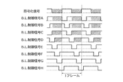
- FIG. 3A is a diagram illustrating B.3 according to Example 1 of the first embodiment.
- FIG. 3B is a diagram illustrating an example of a state before a visible light communication signal is superimposed on an L control signal, and
- FIG. It is a figure which shows an example of the state which superimposed the visible light communication signal on L control signal.
- 3A and 3B show the control of the backlight 190 for each of the eight areas A to H which are the display areas of the divided display surface 110.
- An example in which L control signals A to H are input is shown.
- a hatched portion indicates an area where an encoded signal (visible light communication signal) exists.
- the phase of the encoded signal (visible light communication signal) is superimposed in a certain area of the display area.
- the expression of matching the phases is explained with an example of synchronizing the rising timing, but is not limited thereto. Any time may be used as long as the rise time is determined from the state before the rise start to the rise completion state. In addition, since a delay time in the control signal voltage path occurs, it does not mean that synchronization is only achieved when the timings match, and the phase can be changed even when there is a certain delay time within a certain range. Included in the expression to match. The same applies to the following present disclosure.
- the encoded signal is superimposed at the same timing immediately after the extinguishing period (blanking period). Note that in other regions other than the specific region (reference region), the encoded signal is superimposed in the same phase as the encoded signal of the reference region, but in the extinguishing period (blanking period) when the backlight is extinguished. The encoded signal is not superimposed.
- a region C to which the L control signal C is input is set as a reference region, and B.B shown in FIG.
- the encoded signal is changed to B.B.
- B.B Superimposed on the L control signals A to H in the same phase.
- the second processing unit 170 performs B.B.
- the code signal is superimposed in the ON period of the L control signal, but is not superimposed in the OFF period.
- the reference region is not limited to the region C described above.
- examples of reference areas that can be set in the present embodiment will be described.
- the reference region may be set to the brightest region (region with a short blanking period or region with the highest transmittance of the display panel) among the divided display regions.
- the brightness of the image is determined by the first processing unit 130 based on the video signal, instead of determining the bright area based on the brightness of the display area for each frame.
- a bright area may be determined based on the transition of the center of the height.
- the area including the brightest part of the display area based on the average of the video signal over a certain period of time It may be set as. Note that the reference area may be determined in advance.
- the display device is a display device (100) that can output a visible light communication signal, and is based on the display panel (150) having a display surface for displaying an image and the image signal.
- a display control unit (first control unit 140) for controlling the display panel to display an image on the display surface of the display panel, and a light emitting surface for illuminating the display surface of the display panel (150) from the back side.
- a backlight (190) having a signal processing unit (second processing unit 170) for superimposing the visible light communication signal on a backlight control signal generated based on the video signal, and a backlight (190)
- the light emitting surface is divided into a plurality of regions, and light emission is controlled in each of the plurality of regions in accordance with a backlight control signal output by the signal processing unit (second processing unit 170).
- a backlight control unit (second control unit 180) that provides periods for performing extinguishing control at different timings in each of the plurality of regions
- the signal processing unit includes: When the visible light communication signal is superimposed on the backlight control signal, the encoded signal is not superimposed on a signal indicating that the backlight (190) is turned off in the backlight control signal.
- the signal processing unit (second processing unit 170) superimposes the visible light communication signal on the backlight control signal of each of the plurality of regions, and superimposes each of the plurality of regions.
- the visible light communication signals may be in phase with each other.
- the signal processing unit may match the phase of the visible light communication signal superimposed on each of the plurality of regions with reference to the backlight control signal of a predetermined region among the plurality of regions. Good.
- the predetermined area may be a brightest area among the plurality of areas, and the predetermined area may be an area corresponding to an end portion of the display surface among the plurality of areas. Good.
- total turn-off period This is a period obtained by adding the blanking period, which is the OFF period of the L control signal, and the OFF period of the encoded signal.
- the period during which the backlight 190 is turned off increases by the OFF period of the encoded signal superimposed on the L control signal. That is, in the reference area, when the encoded signal is superimposed, the reference area becomes darker than before the encoded signal is superimposed.
- the encoded signal is not superimposed on the blanking period, only the OFF period of the encoded signal period on which the overlapping encoded signal is not overlapped with the blanking period is backed from the reference area.
- the time during which the light 190 is turned off is shortened. That is, for example, in an area other than the reference area, when the encoded signal is superimposed, the area may become brighter than the reference area.
- two methods of providing an adjustment period during which the backlight 190 is turned on or off can be considered. That is, in the first method, since the total light extinction period of the reference region becomes the longest, there is a method of matching the total light extinction period of other regions with the total light extinction period of the reference region. As a second method, there is a method in which the total light extinction period of all regions is combined with the total light extinction period determined based on the original video signal.
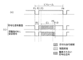
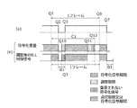
- FIG. 4A B. of the reference area before the encoded signal is superimposed.
- L control signal is shown
- FIG. 4B shows B.B of the reference region after the encoded signal is superimposed.
- the L control signal is shown.
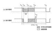
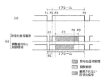
- FIG. 5A B. of another area before the encoded signal is superimposed.
- L control signal is shown.
- FIG. 5B shows B.B in another region after the encoded signal is superimposed. The L control signal is shown.
- the second processing unit 170 displays B. After adjusting the leading edge (rising timing) of the encoded signal at the rising timing (time t12) of the L control signal, An example of superimposing on the L control signal is shown.
- the second processing unit 170 transmits an encoded signal having the same phase as the encoded signal superimposed on the reference region to the B.B. An example of superimposing on the L control signal is shown.
- FIG. 4 and FIG. An example is shown in which the encoded signal is superimposed on the L control signal in the same phase as the other regions simultaneously with the end of the blanking period of the reference region. Note that priority is given to the blanking period of each region as in the first embodiment, and the encoded signal is not superimposed in the blanking period.
- the encoded signal period C1 indicated as the period from time t12 to time t14.
- the total OFF period of the encoded signal (encoded signal extinction period) in one frame indicated as a period from time t11 to time t13 is the encoded signal.
- the encoded signal extinction period T1 encoded signal period C1 ⁇ (1 ⁇ Duty) can be expressed.
- the total extinction period T2 of one frame the blanking period B1 + The encoded signal extinction period T1. That is, the total extinguishing period of the reference area is the longest compared to other areas.
- the encoded signal period and the blanking period may overlap.
- the blanking period is B.B. Since the L control signal has priority over the encoded signal, the encoded signal is not superimposed.
- the second processing unit 170 operates according to the first method that provides an adjustment period for turning on or off the backlight 190, thereby matching the total extinction periods of the respective areas in the screen.
- the second processing unit 170 performs the total extinction per frame of the reference area in the other area according to the first method of matching the total extinction period of the other area with the total extinction period of the reference area.
- An adjustment period for adjusting the difference from the period is provided.
- the time length of the blanking period in each region is the same as a premise.
- the adjustment period A1 indicated as the period from time t24 to time t26 can be expressed as a blanking period B2 ⁇ (1-Duty). That is, the adjustment period in each region other than the reference region can be calculated from the blanking period, the encoded signal period, and the phase of the encoded signal in each region including the reference region.
- FIG. 5B shows an example in which the adjustment period is arranged in one frame indicated as a period from time t21 to time t25.
- the display device 100 causes the second processing unit 170 to provide the adjustment period by the first method. Thereby, the display device 100 converts the encoded signal into the B.P. Although superimposing on the L control signal reduces the brightness of the entire screen (display area) by a certain amount, the encoded signal can be output without greatly changing the image quality itself.
- the second processing unit 170 is preferable when the adjustment period is provided immediately after the encoded signal period, because it can be stably disposed as close as possible to a blanking period where the phase change of the liquid crystal of the display panel 150 is large. This is not a limitation.
- the second processing unit 170 may provide the adjustment period before the time when the next encoded signal is superimposed.
- the adjustment period during which the backlight 190 is turned on or off to adjust the total extinction period can be generally defined as follows, for example. That is, the extinguishing period (blanking period and black video period) of the original backlight 190 based on the video signal is T4, and the encoded signal in the encoded signal period that does not overlap with the blanking period in the encoded signal period. If the total OFF period is T5 and the blanking period after the visible light communication signal is superimposed is T6, the adjustment period can be expressed as T4-T5-T6. As described above, it is desirable to install the adjustment period as close as possible to the blanking period.
- T5 first calculates the total OFF period of the encoded signal period in the encoded signal period, and then subtracts the total OFF period of the encoded signal period that overlaps the blanking period. Can be calculated.
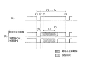
- FIG. 6A to 7D are timing charts for explaining the second method in example 2 of embodiment 1.
- FIG. 6A to 7D are timing charts for explaining the second method in example 2 of embodiment 1.
- B. before the encoded signal is superimposed is shown in the upper part (a).
- L control signal is shown, and B. to B.e. L control signal and B.B adjusted by the second method. L control signal is shown.
- the blanking period is shown as B1
- the encoded signal period is shown as C1.
- the encoded signal is superimposed by the second method.
- the method of adjusting the L control signal is based on the four cases shown in FIGS. 6A to 6D depending on the sum (time sum) of the adjustment period, the encoded signal period, and the blanking period, and the positive / negative relationship of the adjustment period. Divided. Hereinafter, each case will be described.
- FIG. 6A shows an example in which the adjustment period is 0 or more and (adjustment period + encoded signal period + blanking period) is 1 frame or less.
- a part of the adjustment period is arranged in the period from the end time P2 of the blanking period B1 to the start time P3 of the encoded signal period C1, and the remainder of the adjustment period Is placed after the encoded signal period, preferably immediately after (time P5).
- the second processing unit 170 provides the adjustment period shown in the upper part of FIG. 6A (b), so that the encoded signal is superimposed on the B.B. Adjust the L control signal.
- the second control unit 180 can adjust the B.B.
- the backlight 190 is turned off before the start of the encoded signal period C1 even after the blanking period B1, and after the encoded signal period C1 and the encoded signal period C1, the adjustment period P2-P3 The light is turned off until the period is reduced.
- the adjustment period may be provided only between P2 and P3.
- the entire adjustment period may be provided after the end of the encoded signal period C.
- FIG. 6B shows an example in which the adjustment period is 0 or more and (adjustment period + encoded signal period + blanking period) is longer than the length of one frame.
- a part of the adjustment period is arranged in a period from the end time P2 of the blanking period B1 to the time P3 at which the encoded signal period C1 starts, and the rest of the adjustment period Are arranged starting from the end time P4 of one frame.
- the second processing unit 170 provides an adjustment period shown in the upper part of (c) of FIG. 6B, so that the encoded signal is superimposed on the B.C. as shown in the lower part of (c) of FIG. Adjust the L control signal.
- the second control unit 180 can adjust the B.B. According to the L control signal, after the blanking period B1, the backlight 190 is turned off until the start time P3 of the encoded signal period C1, and the period from the time P5 to the time P4 before the end of the encoded signal period C1 is also turned off.
- the adjusted B.D. is adjusted so that the encoded signal is not transmitted from the time P5 that overlaps the rest of the adjustment period and the encoded signal period C1 to the end time P10 of the encoded signal period C1. It is not superimposed on the L control signal (or the signal is turned off).
- FIG. 6C shows an example where the adjustment period is smaller than 0 and (adjustment period + encoded signal period + blanking period) is equal to or shorter than the length of one frame.
- the adjustment period smaller than 0 means an adjustment period during which the backlight 190 is turned on.
- the adjustment period starts from the end time P2 of the blanking period B1, and the period (time period P6 to time P2) is traced back by the time corresponding to the absolute value of the adjustment period. ).
- the second processing unit 170 provides the adjustment period shown in the upper part of (d) of FIG. 6C, so that the encoded signal is superimposed on the B.D. as shown in the lower part of (d) of FIG. Adjust the L control signal.
- the second control unit 180 can adjust the B.B.
- the backlight 190 is turned on during a period from time P6 to time P2 in the blanking period B1.
- FIG. 6D shows an example in which the adjustment period is less than 0 and (adjustment period + encoded signal period + blanking period) is longer than the length of one frame.
- the adjustment period starts from the time P2 when the blanking period B1 ends, and the period (from time P7 to time P2) goes back by the time corresponding to the absolute value of the adjustment period. Period).
- the backlight 190 in the period from time P7 to time P2 in the blanking period B1 is turned on.
- the absolute value of the adjustment period may be longer than the blanking period in view of the negative adjustment period. .
- the time P7 becomes the time P1 or the time before the time P1, and the blanking period does not exist.
- the encoded signal is used as the remaining period excluding the blanking period in the adjustment period. What is necessary is just to light the OFF period of the encoding signal of a period. In other words, the remaining period of the adjustment period may be arranged until a period (time P8) retroactive from time P9, and the lighting of the encoded signal may be stopped to continue lighting.
- the time P8 it is necessary to determine the time P8 because the original blanking period B1 is equal to the sum of the OFF periods obtained by subtracting the period between the times P8 and P9 from the encoded signal period C1.
- the second processing unit 170 causes the second control unit 180 to continue to turn on the backlight 190 from the time P8 until the start of the next blanking period in addition to the blanking period B1. .
- the L control signal can be adjusted.
- B. L control signal is shown, and in the lower (b) to (e), B. L control signal and B.B adjusted by the second method. L control signal is shown.
- a blanking period is shown as B1
- an encoded signal period is shown as C1
- time Q1 to time Q6 are shown as one frame period.
- the encoded signal is superimposed by the second method.
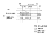
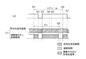
- the method for adjusting the L control signal can be divided into four methods shown in FIGS. 7A to 7D depending on the sum of the adjustment period, the encoded signal period, and the blanking period, and the positive / negative relationship of the adjustment period. Hereinafter, each case will be described.
- FIG. 7A shows an example in which the adjustment period is 0 or more and (adjustment period + encoded signal period + blanking period) is 1 frame or less.
- the adjustment period is arranged starting from time Q4 when the encoded signal period C1 ends.
- the second processing unit 170 provides the adjustment period shown in the upper part of (b) of FIG. 6A, so that the period from time Q4 to time Q5, which is the adjustment period, as shown in the lower part of (b) of FIG. 7A
- the encoded signal is not superimposed in the period from time Q2 to time Q3 that overlaps the blanking period B1. Adjust the L control signal.
- the second control unit 180 can adjust the B.B.
- the backlight 190 is turned off during the period from time Q4 to time Q5 together with the period from time Q2 to time Q3 overlapping with the blanking period B1.
- the backlight 190 is turned off and the encoded signal is not transmitted.
- FIG. 7B shows an example in which the adjustment period is 0 or more and (adjustment period + encoded signal period + blanking period) is 1 frame or more.
- the adjustment period is arranged in a period from time Q8 to time Q6 corresponding to the adjustment period, starting from time Q6 when the encoded signal of the next frame starts. .
- the second processing unit 170 provides the adjustment period shown in the upper part of (c) of FIG. 7B, so that the period from time Q8 to time Q6, which is the adjustment period, as shown in the lower part of (c) of FIG. 7B.
- the encoded signal is not superimposed in the period from time Q2 to time Q3 that overlaps the blanking period B1. Adjust the L control signal.
- the second control unit 180 can adjust the B.B.
- the backlight 190 is turned off during the period from time Q8 to time Q6 together with the period from time Q2 to time Q3 overlapping with the blanking period B1. In the period from time Q8 to time Q6, the backlight 190 is turned off and the encoded signal is not transmitted.
- FIG. 7C shows an example where the adjustment period is smaller than 0 and (adjustment period + encoded signal period + blanking period) is equal to or longer than the length of one frame.
- the adjustment period is set as a starting point at the end time Q3 of the blanking period B1, and the period corresponding to the absolute value of the adjustment period is arranged in a period that goes back.
- the second processing unit 170 provides the adjustment period shown in the upper part of (d) of FIG. 7C, so that the period from time Q9 to time Q3, which is the adjustment period, as shown in the lower part of (d) of FIG. 7C. So that the backlight 190 is turned on.
- the L. control signal is adjusted and the encoded signal is not superimposed in the ranking period B1. Adjust the L control signal.
- the second control unit 180 can adjust the B.B.
- the backlight 190 is turned on during the period from time Q9 to time Q3.
- the encoded signal may be superimposed in the adjustment period.
- the adjustment period may be lengthened by the total of the OFF period of the encoded signal.
- the shortage of the lighting time in the adjustment period is encoded in a predetermined period that goes back from the end time of the encoding period C1 based on the duty ratio of the encoded signal.
- the backlight 190 may be turned on by not superimposing signals.
- FIG. 7D shows an example in which the adjustment period is smaller than 0 and (adjustment period + encoded signal period + blanking period) is longer than the length of one frame.
- the adjustment period is arranged in a period from the end time Q3 of blanking B1 to the time Q10 that goes back the time corresponding to the absolute value of the adjustment period.
- the backlight 190 in the period from the time Q10 to the time Q3 overlapping with the blanking period B1 is turned on.
- this adjustment period may be lengthened by the total of the OFF period of the encoded signal, and the encoded signal may be superimposed on the adjustment period.
- the OFF period of the encoded signal in the encoded signal period may be lit.
- the second processing unit 170 is configured so that the second control unit 180 continues to be lit from time Q11 to the start time Q7 of the next blanking period in addition to the blanking period B1.
- the L control signal can be adjusted.
- the backlight control method for improving moving image characteristics such as backlight scanning and the transmission of the visible light communication signal using the backlight are turned off by the encoded signal of the visible light communication. It is possible to achieve both by making the period uniform or performing adjustment to return to the same level as the original video signal.
- the signal processing unit when superimposing the visible light communication signal on the backlight control signal,
- the signal processing unit when there is a region of the plurality of regions in which the period of the signal indicating that the backlight is turned off and the period of the visible light communication signal to be superimposed are overlapped,
- a lighting adjustment period for adjusting the luminance of the overlapping region may be provided, and the on / off of the backlight control signal may be adjusted in the lighting adjustment period.
- an adjustment period is provided.
- a visible light communication signal encoded signal
- the luminance difference in the display area can be made inconspicuous.
- the reference area is described as a bright area, but may be read as an area where the opening of the display panel 150 is set large.
- Example 3 [2.3.1. Example of operation of second processing unit by second method]
- the brightness of the display surface 110 (display area) of the display panel 150 is made uniform by providing an adjustment period during which the backlight 190 is turned on or off.
- the present invention is not limited to this.
- FIG. 8 is a diagram showing B.3 in Example 3 of the first embodiment. It is a timing chart for demonstrating the method of superimposing a visible light communication signal on L control signal.
- (a) of FIG. The L control signal is shown.
- the description will be made assuming that the signal is detected only by the rising signal of the waveform.
- the luminance of the region is adjusted by changing the duty ratio of the visible light communication signal, that is, the high period of the signal by an amount corresponding to the adjustment period without providing the adjustment period. Good.
- the adjustment period in the second embodiment is a positive number, that is, when adjustment is performed to turn off the backlight 190, as shown in FIG.
- the High period of the L control signal may be shortened.
- the adjustment period in the second embodiment is a negative number, that is, when adjustment is performed to turn on the backlight 190, as shown in FIG.
- the High period of the L control signal may be lengthened.
- B. A case where the duty ratio of the L control signal changes is also conceivable.
- B.I. In order to drive the L control signal at a constant duty ratio in the plane, the adjustment period in the second embodiment calculated by redoing the calculation including the change in the duty ratio, and the high level of the visible light communication signal as in the present embodiment. A method for changing the period may be used in combination.
- the second control unit 180 that performs backlight control may bring the luminance in the visible light communication region closer to the luminance in the region other than the visible light communication region by controlling the current supplied to the backlight 190 in each region. Furthermore, the luminance in the visible light communication region may be made closer to the luminance in the region other than the visible light communication region by a combination of PWM control of the backlight 190 and current control.
- the backlight control method for improving moving image characteristics such as backlight scanning and the transmission of the visible light communication signal using the backlight are turned off by the encoded signal of the visible light communication. It is possible to achieve both by making the period uniform or performing adjustment to return to the same level as the original video signal.
- the signal is detected only by the rising signal, but the present invention is not limited to this.
- B. Maintain the position of the falling part and change the rising position.
- the signal may be detected by the falling signal.
- the encoded signal is superimposed with reference to the rising edge of the L control signal.
- the characteristic timing of the L control signal may be used as a reference, or the synchronization signal of the video signal itself may be used as a reference. Alternatively, a signal delayed for a certain time from the video synchronization signal may be created and used as a reference.
- a display device that can output a visible light communication signal without greatly degrading the image quality of a display image and reduce reception errors of the output visible light communication signal is realized. can do.
- FIG. 9 is a flowchart for explaining the operation of the second processing unit in the second embodiment.
- step S801 the second processing unit 170 re-encodes the visible light communication signal. More specifically, the second processing unit 170 encodes the visible light communication signal and then generates (re-encodes) an encoded signal to which a header or the like is added. In addition, the second processing unit 170 calculates the transmission time of the encoded signal based on the carrier frequency of the encoded signal.
- step S802 the second processing unit 170 determines that the encoded signal length is B.B. It is determined whether or not it is longer than the ON period (lighting time) of the L control signal.
- the second processing unit 170 calculates the B.C. calculated by the first processing unit 130. Based on the duty ratio of the L control signal, the time during which the backlight 190 is lit (lighting time) is compared with the transmission time length of the encoded signal (encoded signal length). When the second processing unit 170 determines that the transmission time length of the encoded signal is shorter (No in S802), the second processing unit 170 proceeds to step S806 and determines that the transmission time length of the encoded signal is longer (Yes in S802), the process proceeds to step S803.
- step S803 the second processing unit 170 determines whether to perform visible light communication. If it is determined that the visible light communication is to be performed (Yes in S803), the second processing unit 170 proceeds to step S804. If it is determined that the visible light communication is not to be performed (No in S803), the second processing unit 170 proceeds to step S809.
- step S804 the second processing unit 170 re-encodes the visible light communication signal.
- the second processing unit 170 is configured such that when the header portion is encoded with a signal array that cannot be normal data, the signal duty ratio of the header portion is substantially OFF. Recreate (re-encode). Thereafter, the second processing unit 170 outputs the last signal of the header portion (the signal indicating the ON state at the end) to the B.B. A process for advancing the transmission start time of the encoded signal is performed so as to match the rising timing of the L control signal. Details will be described later.
- step S805 the second processing unit 170 determines that the encoded signal length is B.B. It is determined whether or not it is longer than the ON period (lighting time) of the L control signal.
- the second processing unit 170 is a B.B.
- the lighting time of the backlight 190 based on the duty ratio of the L control signal is compared with the transmission time length of the encoded signal. If the second processing unit 170 determines that the transmission time length of the encoded signal is shorter (No in S805), the second processing unit 170 determines that the transmission time length of the encoded signal is longer. In the case (Yes in S805), the process proceeds to step S807.
- step S806 the second processing unit 170 performs B.B.
- the encoded signal is superimposed on the portion other than the blanking period of the L control signal (that is, the ON period of the BL control signal) and output to the second control unit 180, and the process is terminated.
- step S807 the second processing unit 170 determines whether to divide the encoded signal. More specifically, first, the second processing unit 170 compares the transmission time length of the re-encoded encoded signal with the lighting time of the backlight 190. Then, if the transmission time length of the encoded signal is longer, the second processing unit 170 determines to divide the encoded signal (Yes in S807), proceeds to step S808, and transmits the transmission time length of the encoded signal. If is shorter, it is determined that the encoded signal is not divided (No in S807), and the process proceeds to step S809.
- step S808 the second processing unit 170 divides the encoded signal so that the length is within the data length that is within the backlight lighting period. Then, the second processing unit 170 adjusts the encoded signal so as to be superimposed on a portion other than the blanking period of the backlight control signal (ON period of the BL control signal), and ends the process.
- step S809 the second processing unit 170 does not transmit the encoded signal to the second control unit 180. That is, the transmission of the visible light communication signal is canceled.
- 10A to 10D are diagrams showing B. It is a figure for demonstrating the specific method of superimposing an encoding signal on L control signal.
- the second processing unit 170 encodes the visible light communication signal using an encoding method such as 4PPM or I-4PPM. This is because, when encoding is performed using 4PPM, I-4PPM, or the like, it can be relatively eased that the luminance greatly changes depending on the signal, and the luminance can be prevented from becoming unstable.
- the visible light communication signal may be encoded using an encoding method such as the Manchester method.
- the encoded signal is composed of a header 90 and a data portion 91 storing a code word and the like. It is assumed that an impossible signal arrangement is used for the header 90 as a data signal.
- the ratio of the high period is determined to be 75% in principle.
- the encoded signal period is shorter than the ON period of the L control signal. That is, as shown in FIG. If it is shorter than the period excluding the blanking period in one frame of the L control signal (that is, the ON period of the BL control signal), the B.L.
- the encoded signal can be superimposed without problems during the ON period of the L control signal.
- the encoded signal period is longer than the ON period of the L control signal, the entire encoded signal including the header is set to B.B. Since it cannot be included in the ON period of the L control signal, the encoded signal is divided and included as described in step S807 above.
- the entire encoded signal including the header is shown in FIG. Since the length of one frame of the L control signal is exceeded, An example in which the encoded signal is divided and superimposed in the ON period of the L control signal is shown.
- the data portion 91 of the encoded signal is divided into a data portion 91-1 and a data portion 91-2, and includes a header 90 and a header 92, respectively. It is superimposed on the ON period of the L control signal.
- the header 92 is a data part 91 obtained by dividing the data part 91-2, and includes a determination signal indicating that the data is a continuation of the data part 91-1.
- FIG. 11 shows B. It is a figure for demonstrating another specific method of superimposing an encoding signal on L control signal.
- FIG. 11 (a) shows an encoded signal encoded by I-4PRM.
- FIG. 11 (b) only the header part of FIG. 11 (a) may be re-encoded by changing the encoding method from I-4PPM to 4PPM.
- the header that has been in the ON state and has finally transitioned to the OFF state is changed to a header that has been in the OFF state and has finally transitioned to the ON state.
- an encoded signal including a header 200 that is an OFF state signal, a header 101 that is an ON state signal, and data 102 is B.P. Superposed on the L control signal.
- the second processing unit 170 encodes the visible light communication signal to generate an encoded signal, superimposes the encoded signal on the backlight control signal as the visible light communication signal, and outputs the encoded signal.
- the signal period indicating that the backlight is turned off in the backlight control signal overlaps with the period of the encoded signal to be superimposed, and a plurality of areas If there is a region, the header portion of the encoded signal is superimposed on the backlight control signal during the signal period indicating that the backlight 190 is turned off, and the portion other than the header portion of the encoded signal is turned off. Is superimposed on the backlight control signal in a period other than the signal period indicating.
- the header 90 of the encoded signal in FIG. It is necessary to subtract from the adjustment period the period during which lighting is performed in the blanking period superimposed on the blanking period of the L control signal.
- a display device that can output a visible light communication signal without greatly degrading the image quality of a display image and reduce reception errors of the output visible light communication signal is realized. can do.
- an example using a header of an encoded signal encoded using a general 4PPM encoding method has been described, but the present invention is not limited to this.
- a header obtained by reversing the ON signal and the OFF signal may be raised during the blanking period.
- the encoding may be performed so that the header has a high duty ratio.
- headers even when the header is superimposed on the blanking period, it may not be able to be entered depending on the length of the blanking period. In that case, several types of headers may be prepared and used according to the length of the blanking period.
- FIG. 12 is a flowchart for explaining the operation of the second process in the third embodiment.
- the second processing unit 170 encodes a visible light communication signal. More specifically, the second processing unit 170 encodes the visible light communication signal and then generates an encoded signal to which a header or the like is added. In addition, the second processing unit 170 calculates the transmission time of the encoded signal based on the carrier frequency of the encoded signal.
- step S1102 the second processing unit 170 divides the display area into a plurality of areas.
- the second processing unit 170 detects a bright area of display. More specifically, the second processing unit 170 detects the brightness of each divided area, and selects the brightest area for display based on this.
- the bright display means B.I. It means not the place where the duty ratio of the L control signal is large but the brightest signal level indicating the light emission energy of the image. The detection of bright places will be described in detail later.
- the second processing unit 170 matches the phase of the encoded signal with a bright display area. More specifically, the second processing unit 170 performs the B.B. B. of all the areas or a part of selected areas (a plurality of selected areas) according to the timing of the L control signal. An encoded signal having the same phase is superimposed on the L control signal.
- B.I. The encoded signal is not superimposed in the blanking period of the L control signal. This is because each B.I. This is equivalent to the operation of calculating the AND of the L control signal and the encoded signal. Note that the operations in steps S801 to S809 in FIG. 9 may be performed as necessary.
- step S1105 the second processing unit 170 determines whether the encoded signal and the blanking period overlap. More specifically, the second processing unit 170 performs the encoding signal period and the B.D. It is determined whether there is an overlapping portion between the blanking period of the L control signal and the encoded signal period and the B.B. When the blanking period of the L control signal does not overlap (Yes in S1105), the process proceeds to step S1106, and the second processing unit 170 converts the encoded signal to B.D. Superimpose it on the L control signal and finish the process. On the other hand, if there is an overlapping part (No in S1105), the process proceeds to S1107.
- step S1107 the second processing unit 170 determines whether to perform a visible light communication signal.
- the process proceeds to step S1108.
- the process proceeds to step S1110, and the second processing unit 170 adjusts the duty ratio so as not to transmit the encoded signal, and ends the process.
- step S1108 the second processing unit 170 changes the phase of the encoded signal, and changes the phase of the encoded signal to the B.B. It is superimposed on the L control signal.
- step S1109 the second processing unit 170 determines whether the blanking period overlaps the bright area. If they do not overlap (No in S1109), the process proceeds to step S1110. If they overlap (Yes in S1109), the process proceeds to S1111.
- step S ⁇ b> 1111 the second processing unit 170 determines whether the processing has been completed for each area. If the process has not been completed (No in S1111), the process returns to S1105. If the processing has been completed (Yes in S1111), the process proceeds to step S1112.
- step S1112 the second processing unit 170 determines whether there is an area where the encoded signal is not superimposed. If there is a region that is not superimposed (No in S1112), the process proceeds to step 1003. If there is no overlapped area (Yes in S1112), the process ends.
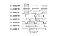
- FIG. 13 is a timing chart showing an example of area group division in the third embodiment
- FIG. 14 is a timing chart showing another example of area group division in the third embodiment.
- the shaded portion indicates a period (coded signal period) in which the encoded signal is superimposed.
- a plurality of display areas are divided into three groups. Specifically, region A, region B, and region C are divided into group G1, region F, region G, and region H are divided into group G2, and region D and region E are divided into group G3. Then, as shown in FIG. 13, in each group, the encoded signal is superimposed at the same timing within the same period. For example, in group G1, the brightest region C is superimposed on the basis, and in group G2, the brightest region E is superimposed on the group.
- a plurality of display areas may be divided into two groups. That is, the region A, the region B, the region C, and the region D may be divided into the group G1, and the region E, the region F, the region G, and the region H may be divided into the group G2.
- the encoded signal is superimposed at the same timing within the same period.
- the signal processing unit includes the backlight of each of a plurality of groups including a plurality of neighboring regions among the plurality of regions.
- the visible light communication signal is superimposed on the control signal, and the visible light communication signals superimposed on each of the plurality of groups are in phase with each other, and the backlight control signal of each of the plurality of groups All of the corresponding visible light communication signals are superimposed in the period for controlling the light emission of the backlight (190).
- this display device Since the encoded signal of the entire encoded signal period can be superimposed on the ON period of the L control signal, reception errors of the output visible light communication signal can be reduced. In other words, B. Since the visible light communication signal can be superimposed without being lost during the ON period of the L control signal, reception errors of the output visible light communication signal can be reduced.
- the signal processing unit (second processing unit 170) is superimposed on each of the plurality of groups based on the backlight control signal in a predetermined region among the plurality of regions included in the plurality of groups.
- the phase of the visible light communication signal may be matched.
- this display device can output the visible light communication signal without further dropping for each of the selected plurality of groups.
- the predetermined area is the brightest area among the plurality of areas.
- the display device 100 can make the difference in luminance in the display area less noticeable.
- phase of the visible light communication signal superimposed on one of the plurality of groups is different from the phase of the visible light communication signal superimposed on the other of the plurality of groups.
- the display device 100 can output the visible light communication signal without further dropping for each of the selected plurality of groups.
- FIG. 15 is a timing chart showing another example of area group division according to the third embodiment.
- a shaded portion indicates a period (encoded signal period) in which the encoded signal is superimposed.
- FIG. 15 is a special example of FIG. 13 and FIG.
- the example shown in FIG. 15 is a special example of FIG. 13 and FIG.
- the encoded signal is not transmitted in a place where encoded signals having the same phase do not enter.
- region A, the region B, the region C, and the region D are divided into other regions and the encoded signals having the same phase are superimposed on the regions A, B, C, and D.
- region D the encoded signal is not superimposed in a period in which the encoded signal overlaps the blanking period. Further, in the example shown in FIG. 15, the encoded signal is not superimposed on the area after area D (area E to area H).
- a reference region is simply determined and the encoded signal is superimposed only on the periphery of the region (neighboring region) It may be allowed.
- the range in which the encoded signal is superimposed may be based on the above-described flowchart or may be limited to a predetermined range.
- the above-described adjustment period may be provided so that a luminance difference does not occur in a region where the encoded signal is superimposed, a region where the encoded signal is not superimposed, and a region where the encoded signal is superimposed.
- B.I Although the rise of the L control signal is superimposed as a reference, other B.
- the characteristic timing of the L control signal may be used as a reference, or the synchronization signal of the video signal itself may be used as a reference. Alternatively, a signal delayed for a certain time from the video synchronization signal may be created and used as a reference.
- the encoded signal is represented by B.I. Even when superposed on the L control signal, priority is given to the blanking period as much as possible, so that lighting during the blanking period is suppressed to avoid degradation of image quality.
- a method for avoiding overlapping of the blanking period and the encoded signal period in as many areas as possible among the plurality of display areas is disclosed. That is, in the present embodiment, a plurality of regions are divided into several groups, and the encoded signal is superimposed at a constant phase within each group. Thereby, the overlap of the blanking period and the encoded signal in the corresponding group can be reduced.
- the regions may be divided into some groups in advance, and how the phase is shifted may be set in advance.
- a plurality of areas are grouped so that the encoded signal length (all of the encoded signal periods) can be superimposed on the basis of the bright area, but the present invention is not limited to this. Since there may be a case where the number of groups divided according to this criterion is very large, the number of groups may be limited. The area divided into groups does not necessarily need to be able to overlap the entire encoded signal period.
- the encoded signals superimposed on the areas in each group may be the same or different. If two or more signals are mixed in the encoded signal obtained on the receiver side, the probability of erroneous recognition or error occurrence increases. Therefore, if two or more signals can be received by the same receiver at the same time, different encoded signals can be received by the same receiver at the same time. It means a case where it can be done or a combination thereof. As a result, the probability of erroneous recognition or error occurrence can be reduced.
- the group to be divided with some reference is not limited to the above example, and the second processing unit 170 may divide into groups based on the signal processing result performed by the relationship between the video signal and the encoded signal. .
- the light source is a very small object that is close to a point light source. Therefore, in order to emit surface light like an LCD, a light guide plate, a diffusion plate, or the like is used. It is spreading. Therefore, when controlling the LEDs in each region, the adjacent regions are designed to overlap, and there is more than a certain amount of leakage light.
- the encoded signal may not be transmitted in the corresponding frame at the corresponding location, or the temporally continuous or overlapping encoded signals may be transmitted in a remote area.
- the encoded signal When the encoded signal is not transmitted in the corresponding frame at the corresponding location, it may be determined and separated from which area the encoded signal is output for each frame, or a specific location (linked to the video signal). May be preferentially transmitted.
- the regions are not continuous or have a fixed interval. This is because the signal can be received when the signal is received by limiting the area. Note that the interval between regions having different phases needs to be determined based on the extent to which the leaked light from the backlight extends, and is a numerical value based on the performance of the display device used.
- the above method may be applied to each area divided into a plurality of blocks.
- the exposure timing is turned on due to a slight phase difference. It may not be acquired as an effective signal because it takes a very short time difference or simultaneously with the start or / and end timing of a series of encoded signal periods or an OFF edge portion.
- the imaging cycle of the image sensor is generally 30 FPS. For example, when the video signal of 60 FPS and the encoded signal are synchronized, if the timing does not match at the time of imaging by the image sensor, it will last forever. It is also conceivable that the timing of the imaging cycle of the image sensor does not match the timing of the encoded signal.
- FIG. 16 is a flowchart for explaining the operation of the second processing unit in the fourth embodiment.
- step S1501 the second processing unit 170 shifts the signal synchronization. More specifically, the second processing unit 170 shifts the synchronization of the encoded signal when the synchronization between the display panel 150 and the backlight 190 is not fixed. This is effective in increasing the probability of imaging of the smartphone 200.
- step S1502 the second processing unit 170 determines the B.D. based on the duty ratio based on the video signal output from the first processing unit 130.
- the AND of the L control signal and the encoded signal is calculated.
- step S1503 the second processing unit 170 adjusts the duty ratio based on the video signal and / or the visible light communication signal.
- the second processing unit 170 checks whether or not the encoded signal period and the blanking period overlap, and provides an adjustment period by dividing into cases. .
- the second processing unit 170 performs B.B of the corresponding frame for the adjustment period.
- the duty ratio of the L control signal is based on the original video signal.
- the second processing unit 170 adjusts the duty ratio by setting a period (OFF period of the BL control signal) for turning off the backlight 190 in a period different from the blanking period. .
- the second processing unit 170 provides the B.B.
- the L control signal is output to the second control unit 180.
- phase relationship between the encoded signal and the video signal when the phase relationship between the encoded signal and the video signal returns to the original state in a certain period, these may be corrected to a predetermined phase difference.
- phase alignment if the phase of the encoded signal and the phase of the video signal change with time at a frequency different from the frequency of the video signal, that is, if either one is not a substantially integer multiple of the other, There is no need to control the phase alignment. This is because, even if the phases of both are not matched, the relationship between the phases of both of them will return to its original state after a certain period of time, and there are always times when it is difficult to receive signals and when they can be easily received. Because it will exist.
- FIG. 17A and FIG. It is a figure for demonstrating the relationship of the phase of L control signal and a visible light communication signal.
- the hatched portion in the figure indicates the period during which the encoded signal is actually transmitted.
- the display is performed to output for a short period with a longer cycle than the L control signal, the signal length relationship may be longer as described above.
- the encoded transmission period is B.B. Desirably shorter than the L control signal.
- B.I While the L control signal X is repeated 12 times, the encoded signal is repeated 7 times.
- the encoded signal is interrupted in the region X, but the encoded signal is always transmitted in some other region. There is no problem because it can be sent.
- the relationship between the video and the communication information may be stored in a buffer or the like, and the previous memory may be extracted and encoded as a communication signal for use. Further, when it takes a very long time for the phase relationship between the two to return to the original state, for example, several seconds or more, the phase relationship may be forcibly returned to the original state. For example, after the encoded signal is completed at f8 in FIG. The phases of the L control signal and the encoded signal may or may not be matched again. In addition, a cycle for adjusting the timing may be performed every second, for example, or may not be performed at all.
- FIG. 18A, FIG. 18B, and FIG. 18C are timing charts for explaining the operation of the second processing unit in the fourth embodiment.
- a shaded portion indicates a region where an encoded signal exists.
- FIG. 18A shows B.B. before superimposing the encoded signal.
- 18B shows a timing chart of the L control signal, and FIG. The timing chart of L control signal is shown.
- FIG. 18C shows that the phase of the backlight control signal and the phase of the visible light communication signal are set as a result by setting the delay time from the rising or falling timing of the backlight control signal as a reference based on the encoded signal. An example in which the relationship is changed with time is shown.
- the synchronization with the L control signal is shifted.
- the timing which can receive an encoding signal by the receiver side, such as the smart phone 200 can be generated reliably.
- the adjustment period described above may be calculated and provided for each phase difference in each frame.
- the time difference ⁇ 1 between the rise U2 of the backlight control signal and the start V2 of the visible light communication signal may be set in advance as a delay time and overlapped with the region A as a reference.
- the time difference ⁇ 2 between the rising edge U3 of the next frame and the start V3 of the visible light communication signal may be the same as or different from ⁇ 1.
- ⁇ represents a positive numerical value (time) due to delay, but may be preceded by a negative numerical value (time).
- the reference region may be anywhere, and may be selected according to the above-described criteria.
- the reference time is the rising edge of the backlight control signal, but another reference characteristic of the signal waveform, such as a falling edge, may be used.
- the reference time may be based on the synchronization signal of the video signal itself, or a signal delayed for a certain time from the video synchronization signal. It may be created and the signal may be used as a reference.
- the video signal and the encoded signal do not have a one-to-one correspondence, some encoded data and image data are buffered in advance in a memory (not shown) in the display device 100 and the like. Processing should be done.
- the cycle of the video signal (1 frame length) and the cycle of superimposing the encoded signal should preferably have the least common multiple within 1 second, and more preferably within 0.5 seconds.
- tracking is performed from the timing at which these two periods are synchronized to the least common multiple period or every integral multiple of the time.
- the shift may be corrected.
- each period is within one second. Even if it does not have the least common multiple, it is not necessary to control the relationship between the two phases, particularly when the rate of change is fast, for example, when a change exceeding the same phase relationship is repeated within one second.
- the change ratio is preferably the relationship as in the above example, but is not necessarily limited thereto.
- the signal processing unit uses the backlight control signal of each of the plurality of regions as a reference with respect to the backlight control signal of each of the plurality of regions.
- the signal processing unit (second processing unit 170) that changes the delay time for encoding the visible light communication signal with respect to the backlight control signal in each of the plurality of regions A delay time for encoding the visible light communication signal (encoded signal) is temporally changed based on the backlight control signal in any one of the areas.
- the signal processing unit (second processing unit 170) superimposes a visible light communication signal (encoded signal) on the plurality of backlight control signals at a period different from the period of the backlight control signal, In each of the plurality of regions, the relationship between the phase of the backlight control signal and the phase of the visible light communication signal may change with the frame.
- the period in which the visible light communication signal different from the period of the backlight control signal is superimposed may change over time.
- phase of the visible light communication signal to be superimposed on the plurality of backlight control signals may be the same in all areas where the visible light communication signal is superimposed.
- phase shift period of the visible light communication signal superimposed on each of the plurality of areas and the one frame period of the backlight control signal may have a least common multiple within 1 sec.
- the timing at which the encoded signal can be received on the receiver side such as the smartphone 200 can surely be generated in a relatively short period of time.
- the signal processing unit includes a phase shift period of the visible light communication signal (encoded signal) superimposed on each of the plurality of regions and one frame of the backlight control signal.
- the start point of the phase shift period of the visible light communication signal (encoded signal) superimposed on each of the plurality of regions is set to one frame period of the backlight control signal every time of the least common multiple or integer multiple of the period. It may be corrected.
- the time indicated by the least common multiple of the two types of periods is usually a numerical value (time) that can be received within at least this time in the positional relationship and environment where the communication signal can be received. It must be within the time that the person who thinks can hold the receiver and wait still. Even in normal NFC, etc., it is recommended to hold it for 1 second as a standard of waiting time, and it is desirable that it is equal or less. Furthermore, the least common multiple is assumed to be within 0.5 seconds as a time that does not cause a psychological burden.
- each region is sequentially controlled to display an image signal at a scanning speed driven at a normal speed.
- each region is displayed at a scanning speed of double speed driving higher than the normal speed.
- the image signal may be displayed by sequentially controlling.
- FIG. 19A and 19B are timing charts for explaining the operation of the second processing unit in the fifth embodiment.
- a shaded portion indicates an area where an encoded signal exists.
- FIG. 19A is a diagram showing B.B. 19B shows a timing chart of the L control signal, and FIG. The timing chart of L control signal is shown.
- L control signals AB There is no period during which the L control signal H is lit simultaneously. That is, it indicates that the encoded signal cannot be simultaneously superimposed on all the display areas.
- the scanning period between the blanking period regions is set to half of the normal period.
- B A region H that is a region where the start of the blanking period of the L control signal is late is selected.
- the second processing unit 170 selects the selected region H at the timing when the blanking period in the region H ends and the backlight 190 starts to be turned on (the time when the BL control signal H is turned ON). The encoded signal is superimposed on.
- the second processing unit 170 performs B.R. B.
- the blanking period with the L control signal H ends.
- the encoded signal is superimposed at the timing when the L control signal H is turned ON.
- the second processing unit 170 can set the period in which the encoded signal is superimposed in any area of the display area for a period of a maximum of 1/2 frame.
- the display control unit (first control unit 140) is configured to display the display panel according to a high-speed scanning speed that is higher than the scanning speed indicated by the video signal.
- the display panel (150) is controlled to display an image on the display surface.
- the display device can take a longer period during which the encoded signal can be output.
- the encoded signal length (encoded signal period) is long.
- the encoded signal is not superimposed in the blanking period in the corresponding area.
- An adjustment period for turning on the backlight 190 in the blanking period may be provided for the turn-off time of the encoded signal superimposed on the ON period of the L control signal. At that time, the adjustment period may be created by the method described in the above embodiment, or the header of the encoded signal may be superimposed on the blanking period. Further, a plurality of areas of the display area may be decomposed into several groups and the encoded signal may be superimposed.
- the same operation may be performed in an area (other area) other than the corresponding area, or no signal may be output.
- the light-off time adjustment period may be provided by the method described in the above embodiment so that the duty ratio based on the visible light communication signal or / and the video signal is the same on the entire screen.
- the brightest region may be selected and the encoded signal may be superimposed at a timing that matches the region.
- B.I Although the rise of the L control signal is superimposed as a reference, other B.
- the characteristic timing of the L control signal may be used as a reference, or the synchronization signal of the video signal itself may be used as a reference. Alternatively, a signal delayed for a certain time from the video synchronization signal may be created and used as a reference.
- the present invention is not limited to this. It is also possible to increase only the scanning speed while leaving the number of frames as it is.
- the second processing unit determines the present embodiment based on the relationship between the video signal and the encoded signal.
- the method of transmitting the signal may be taken. In this case, since the transmission of the signal from the second processing unit 170 to the first processing unit 130 in FIG. 2 is entered, the arrow connecting the two blocks is directed in both directions.
- the backlight scanning is the control method for providing the periods for performing the extinction control at different timings in each of the plurality of regions. Local dimming may be used.
- the display area (screen) is divided into several areas, the transmittance of the liquid crystal in that area is made higher than usual, and the backlight brightness is lowered accordingly (duty is reduced).
- This is a backlight control method for reducing power.
- the power can be reduced by the above control.
- the backlight duty the lighting period is reduced, and as a result, the contrast is improved.
- FIG. 20 is a timing chart showing backlight control when local dimming is applied in the sixth embodiment.
- the interval T of the blanking period start timing is uniform between adjacent areas, but the length of the blanking period is Not uniform.
- the display device 100 has the B.B.B.R. After storing the blanking period of the L control signal, the processing (operation) described below may be performed.
- FIG. 21 is a flowchart for explaining an example of the operation of the second processing unit in the sixth embodiment.
- step S1901 the second processing unit 170 calculates an adjustment period.
- the turn-off time in the encoded signal is N1, and B.B.
- the turn-off time of the L control signal is N2
- step S1902 the second processing unit 170 determines whether the sum (N + C) of the adjustment period N and the encoded signal period C is equal to or shorter than one frame period.
- the processing proceeds to S1903. On the other hand, if the second processing unit 170 determines that (N + C) is greater than one frame period (No in S1902), the process proceeds to S1906, stops outputting the encoded signal, and ends the process.
- step S1903 the second processing unit 170 determines whether or not the adjustment period N is 0 or more.
- the second processing unit 170 proceeds to S1904, and sets the extinguishing period retroactively from the start of the next encoded signal. Also, during this period, no encoded signal is output, and the process is terminated.
- N is smaller than 0 (No in S1903)
- the second processing unit 170 proceeds to S1905, and B.I. Start from the end of the blanking period of the L control signal.
- a lighting period (ON period) corresponding to the adjustment period is provided in the blanking period of the L control signal. Also, the encoded signal is not output during this adjustment period.
- FIG. 22 is a timing chart for explaining an example of the operation of the second processing unit in the sixth embodiment.
- the bold line represents B.I.
- the ON period and the OFF period of the L control signal are shown, and the area A will be described below as a reference area. B. in each figure.
- a region controlled by the L control signal X (X is A to H) is referred to as a region X.
- the second processing unit 170 superimposes the encoded signal having the same phase on each region from the start timing of the frame in the region A, which is the reference region, and provides an adjustment period.
- the adjustment period may be provided according to the second method of the first embodiment, but since the second method has been described above, the description thereof is omitted here.
- the encoded signal is not superimposed.
- the encoded signal is basically superimposed.
- the adjustment period may be converted in consideration of the duty ratio of the encoded signal. In this case, the encoded signal is superimposed and output as long as it is an adjustment period and is a period for outputting the encoded signal. It is good.
- FIG. 23 is a flowchart for explaining an example of the operation of the second processing unit in the sixth embodiment.
- step S2102 the second processing unit 170 determines whether or not the sum (N + C + N3) of the adjustment period N, the encoded signal period C, and the blanking period N3 of the corresponding region is one frame period or less, The determination result is stored.
- step S2103 the second processing unit 170 determines whether the adjustment period N is 0 or more, and stores the determination result.
- the second processing unit 170 After taking the steps as described above, the second processing unit 170 provides an adjustment period based on the determination results of N1 to N3, S2102, and S2103 stored for each region, and provides an adjustment period and the like.
- the visible light communication signal is simultaneously displayed with the video display.
- the adjustment period may be created by a combination with the second method of the first embodiment, the method described in the second to fifth embodiments, or the like.
- FIG. 24 is a timing chart for explaining an example of the operation of the second processing unit in the sixth embodiment.
- the adjustment period is provided by the second method described in the first embodiment.
- the bold line represents B.I.
- the ON period and the OFF period of the L control signal are shown, and the area A will be described below as a reference area.
- the second processing unit 170 outputs encoded signals having the same phase in the period from time P to time Q after the elapse of a predetermined period from the start timing of the frame in the region A as the reference region.
- An adjustment period is provided while overlapping the area. Note that the adjustment period may be provided in accordance with the second method of the first embodiment, but the description of the second method is omitted here because it has been described above.
- the adjustment period may be converted in consideration of the duty ratio of the encoded signal.
- the encoded signal is superimposed and output as long as it is an adjustment period and is a period for outputting the encoded signal. It is good.
- FIG. 25 is a timing chart for explaining an example of the operation of the second processing unit in the sixth embodiment.
- the blanking period of the L control signal varies from frame to frame and from region to region. For this reason, a provisional blanking period (described as a specified blanking period) is determined for the convenience of calculation. Then, the adjustment period can be calculated from the specified blanking period, the encoded signal period, the phase difference between them, and the original blanking period according to the second method of the second embodiment.
- a thick line in FIG. 25 indicates a waveform indicating the original blanking period.
- Specified blanking period is determined based on the average length of the blanking period in the screen and the shortest period.
- the specified blanking period is an extinguishing period in which the encoded signal is not superimposed.
- the encoded signal period is a period in which the encoded signal is superimposed.
- the adjustment period may be provided using the second method of the first embodiment. If the adjustment period is positive, the backlight 190 is turned off during this period. The L control signal may be adjusted. If the adjustment period is negative, the backlight 190 is turned on. The L control signal may be adjusted. When the adjustment period is provided retroactive to the blanking period, the backlight 190 is turned on even during the blanking period. The L control signal may be adjusted. If the adjustment period is negative, the B. When the encoded signal is superimposed on the L control signal, the adjustment period may be corrected based on the duty ratio.
- the backlight control unit follows the backlight control signal output by the signal processing unit (second processing unit 170).
- the light emission is controlled in accordance with the amount of light emitted from the backlight based on each video signal in each of the plurality of areas, and a period for controlling the turn-off at different timings in each of the plurality of areas is provided.
- the duty of the backlight based on the video signal and the visible light communication signal is also changed.
- B.I Although the rise of the L control signal is superimposed as a reference, other B.
- the characteristic timing of the L control signal may be used as a reference, or the synchronization signal of the video signal itself may be used as a reference. Alternatively, a signal delayed for a certain time from the video synchronization signal may be created and used as a reference.
- local dimming may divide an area two-dimensionally, and a video signal may be simultaneously scanned and written in a certain direction.
- the present invention can be applied with the contents described in the present embodiment.
- B.I The case of superimposing on the basis of the rise of the L control signal is described as an example, but the present invention is not limited to this.
- Other B. Falling etc. The characteristic timing of the L control signal may be used as a reference, or the synchronization signal of the video signal itself may be used as a reference. Alternatively, a signal delayed for a certain time from the video synchronization signal may be created and used as a reference.
- the present disclosure can be applied to a display device that can output a visible light communication signal without greatly degrading the image quality of a display image and reduce reception errors of the output visible light communication signal.
- the display device according to the present disclosure can safely and actively acquire information other than images, not only devices such as televisions, PCs, and tablets at home, but also signage on the go
- the information terminal and the information display device can also be applied to various uses such as transfer of image-accompanying information and information transmission in various scenes in the sense that necessary information can be obtained safely because of its activeness.
Landscapes
- Engineering & Computer Science (AREA)
- Physics & Mathematics (AREA)
- Computer Hardware Design (AREA)
- General Physics & Mathematics (AREA)
- Theoretical Computer Science (AREA)
- Electromagnetism (AREA)
- Computer Networks & Wireless Communication (AREA)
- Signal Processing (AREA)
- Liquid Crystal Display Device Control (AREA)
- Control Of Indicators Other Than Cathode Ray Tubes (AREA)
- Transforming Electric Information Into Light Information (AREA)
- Optical Communication System (AREA)
Abstract
Description
近年の表示装置、特に液晶ディスプレイ、及び、液晶を用いたプロジェクターなどの分野においては、画質改善のためにバックライトスキャンと呼ばれる技術が採用されている。ここで、バックライトスキャンとは、液晶の反応速度の遅さと、ホールド型による動画ボケを改善するバックライト制御方法であり、表示画面をいくつかの領域(バックライト領域)に分割し、その領域毎に定期的に順次点灯するようバックライトの発光を制御する。より具体的には、バックライトスキャンとは、バックライト消灯期間を設け、各バックライト領域において、周期的に行う消灯期間(ブランキング期間)のタイミングを異なるようにした制御方法である。一般的にブランキング期間のタイミングを液晶の走査タイミングに合うように制御されることが多い。
以下、図1~8を用いて、実施の形態1を説明する。
図1は、実施の形態1にかかる可視光通信のシステムの一例を示す概略図である。
図1に示す可視光通信システム10は、表示装置100と、スマートフォン200とを備える。
図2は、実施の形態1にかかる表示装置の概略構成の一例を示すブロック図である。
次に、以上のように構成された表示装置100の動作について説明する。
[2.1.1.第2の処理部の動作の一例]
図3Aは実施の形態1の実施例1にかかるB.L制御信号に、可視光通信信号を重畳する前の状態の一例を示す図であり、図3Bは実施の形態1の実施例1にかかるB.L制御信号に、可視光通信信号を重畳した状態の一例を示す図である。
以上のように、本実施例において、表示装置は、可視光通信信号を出力可能な表示装置(100)であって、映像を表示する表示面を有する表示パネル(150)と、映像信号に基づいて前記表示パネルの表示面に映像を表示するよう前記表示パネルを制御する表示制御部(第1の制御部140)と、前記表示パネル(150)の前記表示面を背面から照明する発光面を有するバックライト(190)と、前記可視光通信信号を前記映像信号に基づいて生成されたバックライト制御信号に重畳する信号処理部(第2の処理部170)と、前記バックライト(190)の発光面を複数の領域に分割し、前記信号処理部(第2の処理部170)により出力されたバックライト制御信号に従って、前記複数の領域それぞれにおいて発光の制御を行い、かつ、前記複数の領域それぞれにおいて異なるタイミングで消灯の制御を行う期間を設けるバックライト制御部(第2の制御部180)とを備え、前記信号処理部(第2の処理部170)は、前記可視光通信信号を前記バックライト制御信号に重畳する際に、前記バックライト制御信号のうち前記バックライト(190)の消灯を示す信号に対しては、前記符号化信号を重畳しない。
以下、ブランキング期間の時間長が、表示領域の各領域で同じとして説明する。
まず、図4および図5を用いて、第1の方法による第2の処理部170の動作について説明する。
次に、第2の方法による第2の処理部170の動作について説明する。
図6Aには、調整期間が0以上で、(調整期間+符号化信号期間+ブランキング期間)が1フレームの長さ以下である場合の一例が示されている。
図6Bには、調整期間が0以上で、(調整期間+符号化信号期間+ブランキング期間)が1フレームの長さより長い場合の一例が示されている。
図6Cには、調整期間が0より小さく、(調整期間+符号化信号期間+ブランキング期間)が1フレームの長さ以下の場合の一例が示されている。ここで、0より小さい調整期間とは、バックライト190を点灯する調整期間を意味する。
図6Dには、調整期間が0より小さく、(調整期間+符号化信号期間+ブランキング期間)が1フレームの長さより長い場合の一例が示されている。
図7Aには、調整期間が0以上であり、(調整期間+符号化信号期間+ブランキング期間)が1フレームの長さ以下である場合の一例が示されている。
図7Bには、調整期間が0以上で、(調整期間+符号化信号期間+ブランキング期間)が1フレームの長さ以上である場合の一例が示されている。
図7Cには、調整期間が0より小さく、(調整期間+符号化信号期間+ブランキング期間)が1フレームの長さ以上である場合の一例が示されている。
図7Dには、調整期間が0より小さく、(調整期間+符号化信号期間+ブランキング期間)が1フレームの長さより長い場合の一例が示されている。
以上のように、本実施例によれば、バックライトスキャンなどの動画特性向上のためのバックライト制御法とバックライトを用いた可視光通信信号の送信を、可視光通信の符号化信号による消灯期間を均一化或いは元の映像信号と同等に戻す調整を行うことで両立することができる。
[2.3.1.第2の方法による第2の処理部の動作の一例]
実施例2では、バックライト190を点灯または消灯する調整期間を設けることにより、表示パネル150の表示面110(表示領域)の輝度を均一化したが、これに限らない。
以上のように、本実施例によれば、バックライトスキャンなどの動画特性向上のためのバックライト制御法とバックライトを用いた可視光通信信号の送信を、可視光通信の符号化信号による消灯期間を均一化或いは元の映像信号と同等に戻す調整を行うことで両立することができる。
以上、本実施の形態によれば、表示画像の画質を大きく劣化させることなく可視光通信信号を出力すること、かつ、出力した可視光通信信号の受信ミスを低減することができる表示装置を実現することができる。
実施の形態1では、B.L制御信号のON期間より、符号化信号期間の方が短い場合の表示装置100の動作について説明した。本実施の形態では、B.L制御信号のON期間より、符号化信号期間の方が長い場合の表示装置100の動作について説明する。
以下、第2の処理部170の動作を中心に説明する。
次に、図10A~図10Dおよび図11を用いて、実施の形態2の表示装置100の動作の詳細(具体例)について説明する。
図10A~図10Dは、実施の形態2におけるB.L制御信号に、符号化信号を重畳する具体的方法を説明するための図である。
次に、図10Dとは別の態様について説明する。すなわち、B.L制御信号のON期間より、符号化信号期間の方が長い場合に、符号化信号のヘッダー部分のみをB.L制御信号のブランキング期間に重畳する場合の具体例について説明する。
以上、本実施の形態によれば、表示画像の画質を大きく劣化させることなく可視光通信信号を出力すること、かつ、出力した可視光通信信号の受信ミスを低減することができる表示装置を実現することができる。
本実施の形態では、B.L制御信号のON期間に符号化信号期間すべての符号化信号を重畳できるように、表示領域の複数の領域を幾つかのグループに分割した上で符号化信号を重畳する方法について説明する。
以下では、領域の明るさを基にして、最も明るい領域を中心に、符号化信号を重畳するタイミングを決定する方法を例に挙げて説明する。
次に、図13および図14を用いて、本実施の形態3の表示装置100の詳細(具体例)について説明する。
このように、本実施の形態の表示装置によれば、前記信号処理部(第2の処理部170)は、前記複数の領域のうち近傍の複数の領域を含む複数のグループそれぞれの前記バックライト制御信号に対して、前記可視光通信信号をそれぞれ重畳し、前記複数のグループそれぞれに重畳される前記可視光通信信号は互いに同位相であり、前記複数のグループそれぞれの前記バックライト制御信号の前記バックライト(190)の発光の制御を行う期間に、対応する前記可視光通信信号のすべてが重畳されている。
符号化信号を受信する際に、フォトダイオードなどの応答速度の非常に速い光強度センサーを用いた場合には、画像と符号化信号の位相差は大きな問題にはならない。
以下、第2の処理部170の動作を中心に説明する。
次に、図18Aおよび図18B、図18Cを用いて、実施の形態3の表示装置100の動作の詳細(具体例)について説明する。
以上のように、本実施の形態の表示装置において、前記信号処理部は、前記複数の領域それぞれのバックライト制御信号に対して、前記複数の領域のいずれか一つのバックライト制御信号を基準に、可視光通信信号を符号化する遅延時間を時間的に変化させる、前記信号処理部(第2の処理部170)は、前記複数の領域それぞれの前記バックライト制御信号に対して、前記複数の領域のいずれか一つの前記バックライト制御信号を基準に、前記可視光通信信号(符号化信号)を符号化する遅延時間を時間的に変化させる。
実施の形態1~4では、通常速度で駆動する走査速度にて各領域を順次制御して画像信号を表示する場合について説明したが、通常速度よりも速い倍速駆動の走査速度にて各領域を順次制御して画像信号を表示するとしてもよい。
以下、第2の処理部170の動作を中心に説明する。
以上のように、本実施の形態の表示装置において、前記表示制御部(第1の制御部140)は、前記映像信号に示される走査速度よりも高速化した高速走査速度に従って、前記表示パネルの表示面に映像を表示するよう前記表示パネル(150)を制御する。
実施の形態1~5では、複数の領域それぞれにおいて異なるタイミングで消灯の制御を行う期間を設ける制御方法がバックライトスキャンであるとして説明したがそれに限らない。ローカルディミングであってもよい。
次に、ローカルディミングにより制御されたB.L制御信号について説明する。
以下、第2の処理部170の動作を中心に説明する。なお、本実施の形態では表示領域の各領域の1フレームあたりのOFF期間を揃えた場合の信号制御を示す。
図21は、実施の形態6における第2の処理部の動作の一例を説明するためのフローチャートである。
ローカルディミング時においても、通常のバックライトスキャン制御時と同様に順次ブランキング期間を持つことを優先してもよい。この場合の処理について以下説明する。
図25は、実施の形態6における第2の処理部の動作の一例を説明するためタイミングチャートである。
以上のように、本実施の形態の表示装置において、前記バックライト制御部(第2の制御部180)は、前記信号処理部(第2の処理部170)により出力されたバックライト制御信号に従って、前記複数の領域それぞれにおいて各々の映像信号に基づく前記バックライトの発光量に従って発光の制御を行い、前記複数の領域それぞれにおいて異なるタイミングで消灯の制御を行う期間を設け、前記複数の領域それぞれにおいて前記映像信号および前記可視光通信信号に基づく前記バックライトのデューティも変化させる。
100 表示装置
110 表示面
120 第1の入力部
130 第1の処理部
140 第1の制御部
150 表示パネル
160 第2の入力部
170 第2の処理部
180 第2の制御部
190 バックライト
200 スマートフォン
Claims (20)
- 可視光通信信号を出力可能な表示装置であって、
映像を表示する表示面を有する表示パネルと、
映像信号に基づいて前記表示パネルの表示面に映像を表示するよう前記表示パネルを制御する表示制御部と、
前記表示パネルの前記表示面を背面から照明する発光面を有するバックライトと、
前記可視光通信信号を前記映像信号に基づいて生成されたバックライト制御信号に重畳する信号処理部と、
前記バックライトの発光面を複数の領域に分割し、前記信号処理部により出力されたバックライト制御信号に従って、前記複数の領域それぞれにおいて発光の制御を行い、かつ、前記複数の領域それぞれにおいて異なるタイミングで消灯の制御を行う期間を設けるバックライト制御部とを備え、
前記信号処理部は、前記可視光通信信号を前記バックライト制御信号に重畳する際に、前記バックライト制御信号のうち前記バックライトの消灯を示す信号に対しては、前記可視光通信信号を重畳しない、
表示装置。 - 前記信号処理部は、
前記複数の領域それぞれの前記バックライト制御信号に対して、前記可視光通信信号をそれぞれ重畳し、
前記複数の領域それぞれに重畳される前記可視光通信信号は互いに同位相である、
請求項1に記載の表示装置。 - 前記信号処理部は、
前記複数の領域のうち所定の領域の前記バックライト制御信号を基準に、前記複数の領域それぞれに重畳される前記可視光通信信号の位相を合わせる、
請求項2に記載の表示装置。 - 前記所定の領域は、前記複数の領域のうち最も明るい領域である、
請求項3に記載の表示装置。 - 前記所定の領域は、前記複数の領域のうち前記表示面の端部に対応する領域である、
請求項3に記載の表示装置。 - 前記信号処理部は、
前記複数の領域のうち近傍の複数の領域を含む複数のグループそれぞれの前記バックライト制御信号に対して、前記可視光通信信号をそれぞれ重畳し、
前記複数のグループそれぞれに重畳される前記可視光通信信号は互いに同位相であり、
前記複数のグループそれぞれの前記バックライト制御信号の前記バックライトの発光の制御を行う期間に、対応する前記可視光通信信号のすべてが重畳されている、
請求項1に記載の表示装置。 - 前記信号処理部は、
前記複数のグループに含まれる複数の領域のうち所定の領域の前記バックライト制御信号を基準に、前記複数のグループそれぞれに重畳される前記可視光通信信号の位相を合わせる、
請求項6に記載の表示装置。 - 前記所定の領域は、前記複数の領域のうち最も明るい領域である、
請求項6に記載の表示装置。 - 前記複数のグループの一に重畳される前記可視光通信信号の位相と、前記複数のグループの他に重畳される前記可視光通信信号の位相とは、異なる、
請求項6~8のいずれか1項に記載の表示装置。 - 前記信号処理部は、
前記可視光通信信号を前記バックライト制御信号に重畳する際に、前記バックライト制御信号のうち前記バックライトの消灯を示す信号の期間と、重畳される前記可視光通信信号の期間とが重複する領域であって前記複数の領域のうちの領域がある場合、
前記重複する領域に、前記重複する領域の輝度を調整するための点灯調整期間を設け、前記点灯調整期間において、前記バックライト制御信号のオン・オフを調整する、
請求項1~5のいずれか1項に記載の表示装置。 - 前記信号処理部は、
前記可視光通信信号を符号化して符号化信号を生成し、前記可視光通信信号として前記符号化信号を前記バックライト制御信号に重畳し、
前記符号化信号を前記バックライト制御信号に重畳する際に、前記バックライト制御信号のうち前記バックライトの消灯を示す信号の期間と、重畳される前記符号化信号の期間とが重複する領域であって前記複数の領域のうちの領域がある場合、
前記符号化信号のうちヘッダー部分を、前記バックライトの消灯を示す信号の期間の前記バックライト制御信号に重畳し、前記符号化信号のうちの前記ヘッダー部分以外の部分を、前記バックライトの消灯を示す信号の期間以外の期間の前記バックライト制御信号に重畳する、
請求項1~5のいずれか1項に記載の表示装置。 - 前記信号処理部は、
前記複数のバックライト制御信号に対して、バックライト制御信号の周期と異なる周期で可視光通信信号を重畳し、前記複数の領域それぞれにおいて、前記バックライト制御信号の位相と、前記可視光通信信号の位相との関係がフレームとともに変化する、
請求項1~5のいずれか1項に記載の表示装置。 - 前記バックライト制御信号の周期と異なる可視光通信信号を重畳する周期が、時間的に変化する、
請求項12に記載の表示装置。 - 前記信号処理部は、
前記複数の領域それぞれのバックライト制御信号に対して、前記複数の領域のいずれか一つのバックライト制御信号を基準に、可視光通信信号を符号化する遅延時間を時間的に変化させる、
請求項1~5のいずれか1項に記載の表示装置。 - 前記複数のバックライト制御信号に対して重畳する可視光通信信号の位相が、可視光通信信号を重畳するすべての領域で同じ位相である、
請求項12~14のいずれか1項に記載の表示装置 - 前記複数の領域それぞれに重畳される前記可視光通信信号の位相ずれの周期と、前記バックライト制御信号の1フレーム周期とは、1sec以内に最小公倍数を有する、
請求項12~14のいずれか1項に記載の表示装置。 - 前記信号処理部は、
前記複数の領域それぞれに重畳される前記可視光通信信号の位相ずれの周期と、前記バックライト制御信号の1フレーム周期との最小公倍数または整数倍の時間毎に、前記複数の領域それぞれに重畳される前記可視光通信信号の位相ずれの周期の始点を前記バックライト制御信号の1フレーム周期に補正する、
請求項12~16のいずれか1項に記載の表示装置。 - 前記表示制御部は、前記映像信号に示される走査速度よりも高速化した高速走査速度に従って、前記表示パネルの表示面に映像を表示するよう前記表示パネルを制御する、
請求項1~17のいずれか1項に記載の表示装置。 - 前記バックライト制御部は、
前記信号処理部により出力されたバックライト制御信号に従って、前記複数の領域それぞれにおいて発光の制御を行い、前記複数の領域それぞれにおいて各々の映像信号に基づく前記バックライトの発光量に従って異なるタイミングで消灯の制御を行う期間を設け、前記複数の領域それぞれにおいて、前記映像信号および前記可視光通信信号に基づく前記バックライトのデューティも変化させる、
請求項1~18のいずれか1項に記載の表示装置。 - 可視光通信信号を出力可能な表示装置の制御方法であって、
前記表示装置は、映像を表示する表示面を有する表示パネルと、
前記表示パネルの前記表示面を背面から照明する発光面を有するバックライトとを備え、
前記制御方法は、
映像信号に基づいて前記表示パネルの表示面に映像を表示するよう前記表示パネルを制御する表示制御ステップと、
前記可視光通信信号を前記映像信号に基づいて生成されたバックライト制御信号に重畳する信号処理ステップと、
前記バックライトの発光面を複数の領域に分割し、前記信号処理ステップにおいて出力されたバックライト制御信号に従って、前記複数の領域それぞれにおいて発光の制御を行い、かつ、前記複数の領域それぞれにおいて異なるタイミングで消灯の制御を行う期間を設けるバックライト制御ステップとを含み、
前記信号処理ステップでは、
前記可視光通信信号を前記バックライト制御信号に重畳する際に、前記バックライト制御信号のうち前記バックライトの消灯を示す信号に対しては、前記可視光通信信号を重畳しない、
表示装置の制御方法。
Priority Applications (4)
| Application Number | Priority Date | Filing Date | Title |
|---|---|---|---|
| JP2015543688A JP6430952B2 (ja) | 2013-10-25 | 2014-07-30 | 表示装置およびその制御方法 |
| EP14855722.6A EP3062510B1 (en) | 2013-10-25 | 2014-07-30 | Display apparatus and control method therefor |
| US15/054,573 US10068532B2 (en) | 2013-10-25 | 2016-02-26 | Display device including signal processor that superimposes visible light communication signals on backlight control signals generated based on an image signal |
| US16/050,301 US20180336848A1 (en) | 2013-10-25 | 2018-07-31 | Display device including signal processor that superimposes visible light communication signals on backlight control signals generated based on an image signal |
Applications Claiming Priority (2)
| Application Number | Priority Date | Filing Date | Title |
|---|---|---|---|
| JP2013221934 | 2013-10-25 | ||
| JP2013-221934 | 2013-10-25 |
Related Child Applications (1)
| Application Number | Title | Priority Date | Filing Date |
|---|---|---|---|
| US15/054,573 Continuation US10068532B2 (en) | 2013-10-25 | 2016-02-26 | Display device including signal processor that superimposes visible light communication signals on backlight control signals generated based on an image signal |
Publications (1)
| Publication Number | Publication Date |
|---|---|
| WO2015059852A1 true WO2015059852A1 (ja) | 2015-04-30 |
Family
ID=52992476
Family Applications (1)
| Application Number | Title | Priority Date | Filing Date |
|---|---|---|---|
| PCT/JP2014/003999 Ceased WO2015059852A1 (ja) | 2013-10-25 | 2014-07-30 | 表示装置およびその制御方法 |
Country Status (4)
| Country | Link |
|---|---|
| US (2) | US10068532B2 (ja) |
| EP (1) | EP3062510B1 (ja) |
| JP (1) | JP6430952B2 (ja) |
| WO (1) | WO2015059852A1 (ja) |
Cited By (8)
| Publication number | Priority date | Publication date | Assignee | Title |
|---|---|---|---|---|
| JP2017016071A (ja) * | 2015-07-07 | 2017-01-19 | アルパイン株式会社 | 画像表示装置 |
| JP2017123059A (ja) * | 2016-01-07 | 2017-07-13 | 矢崎エナジーシステム株式会社 | 警報器 |
| WO2017122925A3 (ko) * | 2016-01-12 | 2018-03-08 | 국민대학교 산학협력단 | Dsm-psk 광학 무선 송신 방법 및 장치 |
| JP2018050095A (ja) * | 2016-09-20 | 2018-03-29 | カシオ計算機株式会社 | 報知装置、報知方法及びプログラム |
| WO2019026167A1 (ja) * | 2017-07-31 | 2019-02-07 | 日本電気株式会社 | 通信装置、位相変調型空間光変調素子、動作制御方法、および動作制御プログラム |
| WO2019097882A1 (ja) * | 2017-11-14 | 2019-05-23 | パナソニックIpマネジメント株式会社 | 表示装置および表示方法 |
| KR20190091173A (ko) * | 2018-01-26 | 2019-08-05 | 숭실대학교산학협력단 | 가시광 통신을 위한 2차원 코딩 방법 및 그 장치 |
| CN110364107A (zh) * | 2018-04-09 | 2019-10-22 | 苹果公司 | 射频信号发射诱导显示伪影减轻系统和方法 |
Families Citing this family (7)
| Publication number | Priority date | Publication date | Assignee | Title |
|---|---|---|---|---|
| US10324525B2 (en) | 2016-12-31 | 2019-06-18 | Intel Corporation | Context aware selective backlighting techniques |
| EP3531584A1 (en) * | 2018-02-21 | 2019-08-28 | Vestel Elektronik Sanayi ve Ticaret A.S. | Method for transmitting data in a video and electronic device |
| CN108806580A (zh) * | 2018-06-19 | 2018-11-13 | 京东方科技集团股份有限公司 | 门驱动器控制电路及其方法、显示装置 |
| TWI688808B (zh) * | 2018-12-07 | 2020-03-21 | 友達光電股份有限公司 | 顯示裝置以及背光驅動方法 |
| CN114999405B (zh) * | 2022-05-25 | 2025-05-23 | 京东方科技集团股份有限公司 | 驱动控制装置,驱动控制方法及显示装置 |
| CN117496895A (zh) * | 2022-07-25 | 2024-02-02 | 苏州佳世达电通有限公司 | 显示装置及其背光控制方法 |
| CN118865882A (zh) | 2023-04-27 | 2024-10-29 | 昇佳电子股份有限公司 | 具有光传感器的显示系统及其控制方法 |
Citations (5)
| Publication number | Priority date | Publication date | Assignee | Title |
|---|---|---|---|---|
| WO2006011515A1 (ja) * | 2004-07-28 | 2006-02-02 | Matsushita Electric Industrial Co., Ltd. | 映像表示装置及び映像表示システム |
| JP2007043706A (ja) | 2005-08-01 | 2007-02-15 | Avago Technologies Ecbu Ip (Singapore) Pte Ltd | パルス幅変調された可視光線を用いる通信のための方法と装置 |
| JP2009212768A (ja) | 2008-03-04 | 2009-09-17 | Victor Co Of Japan Ltd | 可視光通信光送信装置、情報提供装置、及び情報提供システム |
| WO2010098020A1 (ja) * | 2009-02-26 | 2010-09-02 | パナソニック株式会社 | バックライト装置およびこれを用いた映像表示装置 |
| JP2013128206A (ja) * | 2011-12-19 | 2013-06-27 | Samsung Yokohama Research Institute Co Ltd | 可視光通信方法およびそれを用いた可視光通信システム。 |
Family Cites Families (8)
| Publication number | Priority date | Publication date | Assignee | Title |
|---|---|---|---|---|
| JP4743846B2 (ja) * | 2005-05-10 | 2011-08-10 | シチズン電子株式会社 | 光通信装置及びそれを用いた情報機器 |
| JP4777030B2 (ja) | 2005-09-27 | 2011-09-21 | 京セラ株式会社 | 送信装置、受信装置、通信方法及び光通信システム |
| JP4751723B2 (ja) | 2006-01-10 | 2011-08-17 | シャープ株式会社 | 液晶表示装置、液晶表示システム |
| JP4767747B2 (ja) | 2006-04-27 | 2011-09-07 | 京セラ株式会社 | 可視光通信のための発光装置およびその制御方法 |
| KR20070109532A (ko) * | 2006-05-11 | 2007-11-15 | 삼성전자주식회사 | 백라이트와 백라이트 구동 방법 및 이를 포함한액정표시장치 |
| KR101583729B1 (ko) | 2009-05-28 | 2016-01-11 | 삼성디스플레이 주식회사 | 표시 장치 |
| KR101653169B1 (ko) | 2010-03-02 | 2016-09-02 | 삼성디스플레이 주식회사 | 가시광 통신 장치 및 그 방법 |
| KR20130013720A (ko) * | 2011-07-28 | 2013-02-06 | 삼성전자주식회사 | Led 백라이트유닛을 구비한 정보 디스플레이 장치에서의 가시광 통신 방법 및 이를 위한 정보 디스플레이 장치 |
-
2014
- 2014-07-30 WO PCT/JP2014/003999 patent/WO2015059852A1/ja not_active Ceased
- 2014-07-30 EP EP14855722.6A patent/EP3062510B1/en active Active
- 2014-07-30 JP JP2015543688A patent/JP6430952B2/ja active Active
-
2016
- 2016-02-26 US US15/054,573 patent/US10068532B2/en active Active
-
2018
- 2018-07-31 US US16/050,301 patent/US20180336848A1/en not_active Abandoned
Patent Citations (5)
| Publication number | Priority date | Publication date | Assignee | Title |
|---|---|---|---|---|
| WO2006011515A1 (ja) * | 2004-07-28 | 2006-02-02 | Matsushita Electric Industrial Co., Ltd. | 映像表示装置及び映像表示システム |
| JP2007043706A (ja) | 2005-08-01 | 2007-02-15 | Avago Technologies Ecbu Ip (Singapore) Pte Ltd | パルス幅変調された可視光線を用いる通信のための方法と装置 |
| JP2009212768A (ja) | 2008-03-04 | 2009-09-17 | Victor Co Of Japan Ltd | 可視光通信光送信装置、情報提供装置、及び情報提供システム |
| WO2010098020A1 (ja) * | 2009-02-26 | 2010-09-02 | パナソニック株式会社 | バックライト装置およびこれを用いた映像表示装置 |
| JP2013128206A (ja) * | 2011-12-19 | 2013-06-27 | Samsung Yokohama Research Institute Co Ltd | 可視光通信方法およびそれを用いた可視光通信システム。 |
Non-Patent Citations (1)
| Title |
|---|
| See also references of EP3062510A4 |
Cited By (15)
| Publication number | Priority date | Publication date | Assignee | Title |
|---|---|---|---|---|
| JP2017016071A (ja) * | 2015-07-07 | 2017-01-19 | アルパイン株式会社 | 画像表示装置 |
| JP2017123059A (ja) * | 2016-01-07 | 2017-07-13 | 矢崎エナジーシステム株式会社 | 警報器 |
| WO2017122925A3 (ko) * | 2016-01-12 | 2018-03-08 | 국민대학교 산학협력단 | Dsm-psk 광학 무선 송신 방법 및 장치 |
| US10560193B2 (en) | 2016-01-12 | 2020-02-11 | Kookmin University Industry Academy Cooperation Foundation | DSM-PSK optical wireless transmission method and device |
| JP2018050095A (ja) * | 2016-09-20 | 2018-03-29 | カシオ計算機株式会社 | 報知装置、報知方法及びプログラム |
| WO2019026167A1 (ja) * | 2017-07-31 | 2019-02-07 | 日本電気株式会社 | 通信装置、位相変調型空間光変調素子、動作制御方法、および動作制御プログラム |
| JPWO2019026167A1 (ja) * | 2017-07-31 | 2020-07-27 | 日本電気株式会社 | 通信装置、位相変調型空間光変調素子、動作制御方法、および動作制御プログラム |
| JPWO2019097882A1 (ja) * | 2017-11-14 | 2020-12-17 | パナソニックIpマネジメント株式会社 | 表示装置および表示方法 |
| WO2019097882A1 (ja) * | 2017-11-14 | 2019-05-23 | パナソニックIpマネジメント株式会社 | 表示装置および表示方法 |
| JP7209195B2 (ja) | 2017-11-14 | 2023-01-20 | パナソニックIpマネジメント株式会社 | 表示装置および表示方法 |
| US11132964B2 (en) | 2017-11-14 | 2021-09-28 | Panasonic Intellectual Property Management Co., Ltd. | Display device and display method |
| KR20190091173A (ko) * | 2018-01-26 | 2019-08-05 | 숭실대학교산학협력단 | 가시광 통신을 위한 2차원 코딩 방법 및 그 장치 |
| KR102105094B1 (ko) * | 2018-01-26 | 2020-04-27 | 숭실대학교산학협력단 | 가시광 통신을 위한 2차원 코딩 방법 및 그 장치 |
| CN110364107B (zh) * | 2018-04-09 | 2022-11-25 | 苹果公司 | 射频信号发射诱导显示伪影减轻系统和方法 |
| CN110364107A (zh) * | 2018-04-09 | 2019-10-22 | 苹果公司 | 射频信号发射诱导显示伪影减轻系统和方法 |
Also Published As
| Publication number | Publication date |
|---|---|
| EP3062510A1 (en) | 2016-08-31 |
| EP3062510A4 (en) | 2016-10-12 |
| US10068532B2 (en) | 2018-09-04 |
| JP6430952B2 (ja) | 2018-11-28 |
| EP3062510B1 (en) | 2017-11-08 |
| JPWO2015059852A1 (ja) | 2017-03-09 |
| US20160180779A1 (en) | 2016-06-23 |
| US20180336848A1 (en) | 2018-11-22 |
Similar Documents
| Publication | Publication Date | Title |
|---|---|---|
| JP6430952B2 (ja) | 表示装置およびその制御方法 | |
| US10354599B2 (en) | Display method | |
| JP6282601B2 (ja) | 表示装置 | |
| JP5976993B2 (ja) | シャッターめがね、ディスプレイ装置及びこの制御方法 | |
| JP6666022B2 (ja) | 画像表示装置、画像出力装置、及び、それらの制御方法 | |
| US11178367B2 (en) | Video display apparatus, video display system, and luminance adjusting method of video display apparatus | |
| US10181296B2 (en) | Display device and display method | |
| US20120007969A1 (en) | Method for reducing left-eye/right-eye crosstalk in a 3d liquid crystal display device and related display system | |
| US7880713B2 (en) | Method of increasing efficiency of video display and related apparatus | |
| US9704443B2 (en) | Liquid crystal display apparatus and display method | |
| US9438892B2 (en) | Video display device | |
| US20120019632A1 (en) | Display device, shutter device, shutter control circuit, method of controlling shutters, and display system | |
| US20130016196A1 (en) | Display apparatus and method for displaying 3d image thereof | |
| JP2015520406A (ja) | Sei情報を用いたディスプレイ電力低減 | |
| US7623185B2 (en) | Synchronization control apparatus and method | |
| JP7209195B2 (ja) | 表示装置および表示方法 | |
| KR101552886B1 (ko) | 동영상의 화질 개선 장치 및 방법 | |
| US20150085189A1 (en) | Digital television, television chip and display method | |
| KR20190029534A (ko) | 하이 다이내믹 레인지를 위한 구역 백라이트 메타데이터의 전달을 위한 방법 및 장치 | |
| KR101674408B1 (ko) | 셔터 안경, 디스플레이장치 및 이들의 제어방법 | |
| JP2008072300A (ja) | 映像表示装置 | |
| JP2007256355A (ja) | 表示方法及び表示装置 | |
| JP2009100428A (ja) | 映像表示装置及び信号処理方法 |
Legal Events
| Date | Code | Title | Description |
|---|---|---|---|
| 121 | Ep: the epo has been informed by wipo that ep was designated in this application |
Ref document number: 14855722 Country of ref document: EP Kind code of ref document: A1 |
|
| ENP | Entry into the national phase |
Ref document number: 2015543688 Country of ref document: JP Kind code of ref document: A |
|
| REEP | Request for entry into the european phase |
Ref document number: 2014855722 Country of ref document: EP |
|
| WWE | Wipo information: entry into national phase |
Ref document number: 2014855722 Country of ref document: EP |
|
| NENP | Non-entry into the national phase |
Ref country code: DE |