WO2015059899A1 - 基地局装置、通信装置、制御方法及びプログラム - Google Patents
基地局装置、通信装置、制御方法及びプログラム Download PDFInfo
- Publication number
- WO2015059899A1 WO2015059899A1 PCT/JP2014/005204 JP2014005204W WO2015059899A1 WO 2015059899 A1 WO2015059899 A1 WO 2015059899A1 JP 2014005204 W JP2014005204 W JP 2014005204W WO 2015059899 A1 WO2015059899 A1 WO 2015059899A1
- Authority
- WO
- WIPO (PCT)
- Prior art keywords
- base station
- station apparatus
- communication
- enb
- receiving
- Prior art date
- Legal status (The legal status is an assumption and is not a legal conclusion. Google has not performed a legal analysis and makes no representation as to the accuracy of the status listed.)
- Ceased
Links
Images






Classifications
-
- H—ELECTRICITY
- H04—ELECTRIC COMMUNICATION TECHNIQUE
- H04W—WIRELESS COMMUNICATION NETWORKS
- H04W76/00—Connection management
- H04W76/10—Connection setup
- H04W76/19—Connection re-establishment
-
- H—ELECTRICITY
- H04—ELECTRIC COMMUNICATION TECHNIQUE
- H04W—WIRELESS COMMUNICATION NETWORKS
- H04W24/00—Supervisory, monitoring or testing arrangements
- H04W24/04—Arrangements for maintaining operational condition
-
- H—ELECTRICITY
- H04—ELECTRIC COMMUNICATION TECHNIQUE
- H04W—WIRELESS COMMUNICATION NETWORKS
- H04W36/00—Hand-off or reselection arrangements
- H04W36/16—Performing reselection for specific purposes
-
- H—ELECTRICITY
- H04—ELECTRIC COMMUNICATION TECHNIQUE
- H04W—WIRELESS COMMUNICATION NETWORKS
- H04W36/00—Hand-off or reselection arrangements
- H04W36/16—Performing reselection for specific purposes
- H04W36/22—Performing reselection for specific purposes for handling the traffic
-
- H—ELECTRICITY
- H04—ELECTRIC COMMUNICATION TECHNIQUE
- H04W—WIRELESS COMMUNICATION NETWORKS
- H04W76/00—Connection management
- H04W76/10—Connection setup
- H04W76/15—Setup of multiple wireless link connections
-
- H—ELECTRICITY
- H04—ELECTRIC COMMUNICATION TECHNIQUE
- H04W—WIRELESS COMMUNICATION NETWORKS
- H04W76/00—Connection management
- H04W76/30—Connection release
-
- H—ELECTRICITY
- H04—ELECTRIC COMMUNICATION TECHNIQUE
- H04W—WIRELESS COMMUNICATION NETWORKS
- H04W76/00—Connection management
- H04W76/30—Connection release
- H04W76/34—Selective release of ongoing connections
- H04W76/36—Selective release of ongoing connections for reassigning the resources associated with the released connections
-
- H—ELECTRICITY
- H04—ELECTRIC COMMUNICATION TECHNIQUE
- H04W—WIRELESS COMMUNICATION NETWORKS
- H04W36/00—Hand-off or reselection arrangements
- H04W36/0005—Control or signalling for completing the hand-off
- H04W36/0055—Transmission or use of information for re-establishing the radio link
- H04W36/0069—Transmission or use of information for re-establishing the radio link in case of dual connectivity, e.g. decoupled uplink/downlink
- H04W36/00698—Transmission or use of information for re-establishing the radio link in case of dual connectivity, e.g. decoupled uplink/downlink using different RATs
-
- H—ELECTRICITY
- H04—ELECTRIC COMMUNICATION TECHNIQUE
- H04W—WIRELESS COMMUNICATION NETWORKS
- H04W36/00—Hand-off or reselection arrangements
- H04W36/24—Reselection being triggered by specific parameters
- H04W36/30—Reselection being triggered by specific parameters by measured or perceived connection quality data
- H04W36/305—Handover due to radio link failure
-
- H—ELECTRICITY
- H04—ELECTRIC COMMUNICATION TECHNIQUE
- H04W—WIRELESS COMMUNICATION NETWORKS
- H04W76/00—Connection management
- H04W76/30—Connection release
- H04W76/34—Selective release of ongoing connections
Definitions
- the present invention relates to a base station device, a communication device, a control method, and a program, and more specifically to a connection control technique in a wireless communication system.
- a terminal connects to at least one of geographically dispersed base stations to perform wireless communication.
- wireless communication in order to receive signals accurately, the reception power of signals on the receiving side and the radio quality such as signal-to-interference and noise power ratio are maintained at a predetermined level or higher, causing problems in the radio link. Not required.
- the terminal when it is detected that a radio problem has occurred with the base station apparatus (eNB), the terminal (UE) waits for a predetermined time in order to determine whether an RLF has occurred. Then, if the radio problem is not solved even after the predetermined time has elapsed, the UE determines that RLF has occurred and tries to reconnect to the eNB that has been connected for another predetermined time. To do. The radio link is disconnected after the reconnection attempt by the UE for another predetermined time has failed.
- eNB base station apparatus
- the present invention has been made in view of the above-described problems.
- the object is to shorten at least one of the time until connection is started.
- a base station apparatus is the base station apparatus in a wireless communication system in which the communication apparatus can be simultaneously connected to the base station apparatus and the first other base station apparatus.
- a base station apparatus is the base station apparatus in a wireless communication system in which the communication apparatus can be simultaneously connected to the base station apparatus and the first other base station apparatus.
- the base station apparatus releases the connection between the first other base station apparatus and the communication apparatus in response to receiving the first message.
- a base station apparatus is the base station apparatus in a wireless communication system in which the communication apparatus can be simultaneously connected to the base station apparatus and the first other base station apparatus, Receiving means for receiving, from a communication device, a notification regarding the first radio quality of the radio link transmitted when a failure occurs in the radio link between the communication device and the first other base station device. And a transmission means for transmitting, to the first other base station apparatus, a first message indicating that the failure has occurred in response to receiving the notification. The base station apparatus releases the connection between the first other base station apparatus and the communication apparatus in response to receiving the first message.
- a communication apparatus is a communication apparatus that can be simultaneously connected to the first base station apparatus and the second base station apparatus, and is a wireless link between the second base station apparatus and the second base station apparatus.
- the communication device includes a transmission unit that transmits a notification that the failure has occurred to the first base station device, and the communication device is transmitted to the second base station device by transmitting the notification.
- the first base station apparatus is controlled so as to cancel the connection with the first base station apparatus.
- a communication apparatus is a communication apparatus that can be simultaneously connected to the first base station apparatus and the second base station apparatus, and wirelessly communicates with the second base station apparatus.
- a transmission unit configured to periodically transmit a notification regarding the first radio quality of the link to the first base station apparatus, and transmitting the notification when the first radio quality is equal to or lower than a predetermined level.
- the first base station apparatus is controlled to cause the second base station apparatus to release the connection with the communication apparatus.
- a communication apparatus is a communication apparatus that can be simultaneously connected to the first base station apparatus and the second base station apparatus, and is connected to the second base station apparatus.
- the radio base station has a transmission unit that transmits a notification regarding the first radio quality of the radio link to the first base station apparatus, and transmits the notification to the second base station.
- the first base station apparatus is controlled to cause the station apparatus to release the connection with the communication apparatus.
- a time until a radio resource is released after a radio link failure occurs and a time until a terminal starts a connection to a base station apparatus different from the one to which the terminal has been connected. At least one of the above can be shortened.
- the accompanying drawings are included in the specification, constitute a part thereof, show an embodiment of the present invention, and are used to explain the principle of the present invention together with the description.
- the conceptual diagram which shows the example of arrangement
- the conceptual diagram which shows the example of communication between the terminal and multiple eNB by Dual Connectivity.
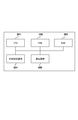
- the figure which shows the hardware structural example of a base station apparatus (eNB) and a communication apparatus (terminal).
- the block diagram which shows the function structural example of eNB.
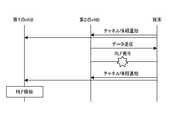
- the sequence diagram which shows the example of the flow of a process until eNB detects that the radio link failure occurred.
- the sequence diagram which shows another example of the flow of a process until eNB detects that the radio link failure occurred The sequence diagram which shows another example of the flow of a process until eNB detects that the radio link failure occurred.
- the sequence diagram which shows an example of the flow of a process after a radio link failure is detected.
- the sequence diagram which shows another example of the flow of a process after a radio link failure is detected.
- the sequence diagram which shows another example of the flow of a process after a radio link failure is detected.
- the present embodiment is premised on a wireless communication system in which Dual Connectivity (see Non-Patent Document 1), which is discussed in the standardization activity of LTE Release 12 of the 3rd Generation Partnership Project (3GPP), is used. Therefore, first, the Dual Connectivity will be described.
- Dual Connectivity see Non-Patent Document 1
- 3GPP 3rd Generation Partnership Project
- small cells small cells
- frequency bands for example, higher frequency bands than those used in macro cells
- a plurality of small cells using the 3.5 GHz band frequency band are placed in the coverage area of the macro cell using the 2 GHz band frequency band.
- Dual Connectivity in such an environment, two types of base station apparatuses cooperate in a layer higher than the MAC (medium access control) layer.
- the two types of base station apparatuses are a master eNB (for example, a macro base station) and a secondary eNB (for example, a small cell base station).
- the master eNB leads communication control, and the secondary eNB Operates based on control.
- Dual Connectivity it is assumed that two types of base station apparatuses are connected by a wired or wireless backhaul line, and for example, traffic transmitted to the terminal is passed to the secondary eNB via the master eNB. Yes.
- the downlink signal reaches the terminal by being transmitted as a radio signal directly from the master eNB to the terminal or by being transmitted as a radio signal from the secondary eNB to the terminal after being transferred from the master eNB to the secondary eNB.
- the uplink signal reaches the master eNB when the terminal directly transmits to the master eNB or when the secondary eNB transfers a signal transmitted from the terminal to the secondary eNB to the master eNB. Note that communication between the terminal and another device directly connected to the secondary eNB may not pass through the master eNB.
- control data for maintaining mobility and data with high real-time properties such as voice call traffic are transmitted from the master eNB to the terminal.
- best-effort user data (U-plane) that does not require real-time performance such as Web browsing is transmitted from the secondary eNB to the terminal.
- the description will be made on the assumption that the system adopts LTE.
- any other wireless communication system may be used as long as the terminal can be connected to a plurality of base station apparatuses simultaneously.
- the terminal is a mobile unit or a fixed radio communication device, and may correspond to a radio communication system other than LTE.
- FIG. 2 although the example which has only one secondary eNB is shown, multiple secondary eNBs may exist and a terminal may be connected with one master eNB and several secondary eNBs.
- FIG. 2 shows the case where only one terminal exists, the following discussion can be applied to any of the cases where one or more terminals exist. .
- the secondary eNB may not always be associated with one master eNB, and any one of the plurality of master eNBs may be selected and associated with the secondary eNB according to the situation.
- a terminal determines a radio link failure (RLF)
- RLF radio link failure
- it tries to reconnect to an eNB that has been connected so far, and after reconnection fails, tries to connect to another eNB. It was.
- the terminal does not have information about the other eNB of the connection switching destination, and a great amount of time is required until the connection to the other eNB is established.
- the eNB that has been connected so far continues to transmit a signal addressed to the terminal, and continues to allocate radio resources to the terminal. As a result, there is a problem that radio resources are wasted.
- this problem is solved by using Dual Connectivity.
- a terminal in a dual connectivity state even if a failure occurs in a radio link with one eNB (for example, a secondary eNB), a failure may not occur in a radio link with another eNB (for example, a master eNB). It is done.
- a terminal in the Dual Connectivity state notifies the second eNB that RLF has occurred, for example, when RLF with the first eNB occurs. Then, the second eNB that has received the notification that the RLF has occurred confirms that the RLF has occurred to the first eNB through the backhaul line in order to release the radio link in which the failure has occurred.
- the first eNB releases the radio connection with the terminal and releases the radio resource. By doing so, it is possible to prevent the first eNB from continuing to allocate radio resources to terminals for a long time, and it is possible to prevent waste of radio resources.
- the second eNB may notify the terminal that the connection to the first eNB should be canceled and the single connectivity state should be entered. As a result, the terminal does not attempt to reconnect to the first eNB, and thus the battery consumption of the terminal can be minimized.
- the first eNB in which RLF has occurred in the radio link with the terminal or the second eNB in which no RLF has occurred switches the connection of the third eNB different from these eNBs to the terminal. It may be determined as a destination.
- the second eNB notifies the terminal of information on the third eNB.
- the terminal performs connection processing with the third eNB using the notified switching destination information, that is, the information of the third eNB.
- the terminal can acquire the information of the switching destination eNB from the eNB that is currently connected, and thus switches the connection destination at high speed. be able to.
- an eNB in which no RLF has occurred causes the eNB in which the RLF has occurred to release the connection with the terminal, thereby releasing the radio resources, thereby Waste can be suppressed.
- the terminal is notified that the connection with the original eNB of the connection destination is released, and the terminal does not attempt to reconnect to the eNB, thereby suppressing the battery consumption of the terminal. Can do.
- an eNB in which no RLF has occurred can notify the terminal of the information of the eNB that is the connection switching destination, thereby speeding up the switching of the connection to the eNB that is the next connection destination of the terminal. .
- FIG. 3 is a diagram illustrating a hardware configuration example of an eNB (base station apparatus, master eNB or secondary eNB) and a terminal (mobile / fixed communication apparatus).
- the eNB and the terminal have the same hardware configuration as illustrated in FIG. 3, and include, for example, a CPU 301, a ROM 302, a RAM 303, an external storage device 304, and a communication device 305.
- the CPU 301 executes a program that realizes the following functions of the eNB and the terminal, which are recorded in any of the ROM 302, the RAM 303, and the external storage device 304.
- eNB and a terminal control the communication apparatus 305 by CPU301, for example, perform communication between a master eNB or a secondary eNB, and a terminal, or communication between eNBs between a master eNB and a secondary eNB.
- the eNB and the terminal have one communication device 305.
- the eNB may have a communication device for communication between eNBs and a communication device with the terminal.
- the terminal may have a plurality of communication devices corresponding to each of a plurality of frequency bands, for example.
- the eNB and the terminal may be provided with dedicated hardware that executes each function described below, or may be executed by a computer that executes a part of the hardware and executes other parts. Good. Further, all the following functions may be executed by a computer and a program.
- FIG. 4 is a block diagram illustrating a functional configuration example of the eNB.
- the eNB includes, for example, a wireless communication unit 401, a wired communication unit 402, a failure detection unit 403, and a control unit 404.
- the eNB includes a data holding unit 405.
- An eNB can be either a master eNB or a secondary eNB.
- eNB can further have another function part with which normal eNB is provided, in this embodiment, in order to simplify description, description is abbreviate
- the wireless communication unit 401 is a functional unit that performs wireless communication with a terminal.
- the wired communication unit 402 is a functional unit that performs wired communication with other eNBs via, for example, the X2 interface.
- the failure detection unit 403 detects from the signal received via the wireless communication unit 401 whether a failure has occurred in a wireless link between another eNB and the terminal.
- the control unit 404 controls the wireless communication unit 401 based on the state of the wireless link between the terminal and each of the plurality of eNBs, and transmits a message to another eNB via the wired communication unit 402. To instruct communication control to other eNBs.
- the communication with other eNBs is described as being performed by the wired communication unit 402. However, the present invention is not limited to this. For example, communication with other eNBs is performed through a wireless line. Also good.
- the wireless communication unit 401 waits for a signal related to the state of the wireless link from the terminal. At this time, it is assumed that the radio communication unit 401 transmits data in the downlink to the terminal in parallel.
- the signal related to the state of the radio link is, for example, a notification indicating that a failure has occurred in the radio link between the terminal and another eNB.
- the signal related to the state of the radio link may include information related to the radio quality of the radio link between the terminal and another eNB. Further, a signal related to the state of the radio link including information related to the radio quality may be periodically transmitted by the terminal.
- the terminal determines the radio quality (for example, reference signal reception power, reference signal reception quality, signal-to-interference and noise power ratio) of a received signal in a radio link with a plurality of connected eNBs and a significant signal. Radio quality related to received signals from other eNBs that can be received with power is received. Note that the information related to the wireless quality may be transmitted separately from the notification indicating that a failure has occurred when a failure occurs, or the information related to the wireless quality is transmitted as information indicating that a failure has occurred. Also good. Information included in the signal related to the state of the wireless link received by the wireless communication unit 401 is input to the failure detection unit 403.
- the radio quality for example, reference signal reception power, reference signal reception quality, signal-to-interference and noise power ratio
- the failure detection unit 403 detects whether a failure has occurred in the radio link between the terminal and another eNB based on the input information. For example, when the notification itself that the failure has occurred is received from the terminal, the failure detection unit 403 confirms that the failure has occurred in the radio link between the terminal and another eNB based on the notification. Detect. Also, for example, when a failure occurs in the radio link between the terminal and another eNB, if the radio quality information of the radio link is transmitted from the terminal, the radio quality information is input. By this, it is detected that a failure has occurred in the radio link between the terminal and another eNB.
- the failure detection unit 403 determines that the radio communication quality between the terminal and the other eNB is less than a predetermined level based on the information. Detects that a radio link has failed. The failure detection unit 403 may determine that an RLF has occurred when a predetermined period of time has elapsed in which the wireless quality has dropped below a predetermined level. Further, when the wireless quality tends to improve, the failure detection unit 403 may continue to observe the wireless quality for a longer period. When the wireless quality tends to deteriorate, RLF occurs early. It may be determined that When a failure is detected, this is notified to the control unit 404.
- the control unit 404 When the control unit 404 receives a notification that a failure has occurred in the radio link between the terminal and the other eNB, the failure of the wireless link between the terminal and the other eNB has occurred. Is generated, and the message is transmitted via the wired communication unit 402. The transmission of this message notifies other eNBs that have a failure in the radio link with the terminal that the radio connection with the terminal should be released. In response to receiving this notification, the other eNB releases the radio connection with the terminal and releases the radio resource.
- the control unit 404 When a failure occurs in the radio link between the terminal and the other eNB, the control unit 404 further indicates to the terminal that the radio connection with the other eNB should be released.
- the wireless communication unit 401 is controlled so as to be transmitted.
- the terminal does not perform the reconnection process (and the transition process of connection to another eNB) of the radio link in which a failure has occurred with the other eNB.
- the wireless connection between the terminal and the other eNB is released as it is, and the reconnection process is not performed, thereby suppressing the battery consumption of the terminal.
- control unit 404 may determine an eNB that is a connection switching destination based on, for example, information on the radio quality received from the terminal.
- the eNB that is the connection switching destination may be determined in the eNB in which the RLF has occurred.
- information on the determined switching destination eNB is acquired via the wired communication unit 402.
- the information is notified from the eNB in which the RLF has not occurred to the eNB in which the RLF has occurred. May be.
- the control unit 404 When the switching destination eNB is determined, the control unit 404 notifies the terminal of information related to the switching destination eNB instead of a message indicating that the wireless connection with another eNB should be released.
- the wireless communication unit 401 is controlled to transmit.
- the information regarding the switching destination eNB is, for example, information for the terminal to establish a connection to the switching destination eNB.
- the wired communication unit 402 determines that the wireless connection with the terminal should be released. A message to be transmitted to another eNB is transmitted.
- the control unit 404 determines another eNB to which the terminal is switched, the wired communication unit 402 is connected to the terminal as a switching destination with respect to the other eNB under the control of the control unit 404. Send a message requesting what to do. Thereafter, when the wired communication unit 402 receives a message indicating that the request has been approved, the control unit 404 transmits the information related to the connection switching destination eNB to the terminal after the approval. Thus, the wireless communication unit 401 is controlled.
- the wired communication unit 402 may receive data to be transmitted to the terminal (for example, data that has failed to be transmitted) from another eNB in which the RLF has occurred. Also, the wired communication unit 402 receives only information (for example, data ID) specifying data to be transmitted to the terminal from other eNBs in which the RLF has occurred, and the data held in the data holding unit 405 is received. The ID may be specified and acquired.
- data ID for example, when the eNB is the master eNB, temporarily holds the data transmitted by other eNBs (secondary eNBs) that are related to each other in the dual connectivity when the master eNB transfers the data. Can be realized.
- the data to be transmitted to the terminal acquired in this manner is transferred to the switching destination eNB when the switching destination eNB exists, and when such an eNB does not exist, the data is transmitted through the wireless communication unit 401 to the terminal. Wirelessly transmitted.
- the wired communication unit 402 can know that an RLF has occurred by receiving a message indicating that a radio link failure has occurred from another eNB.
- the control unit 404 controls the wireless communication unit 401 to cancel the wireless connection with the terminal.
- radio resources can be released at an early stage after RLF occurs, and waste of radio resources can be prevented.
- the control unit 404 controls the wired communication unit 402 so as to transmit data to be transmitted to the terminal or information specifying the data to the eNB that is the transmission source of the message indicating that the failure of the radio link has occurred. Control. Thereby, the data to be transmitted to the terminal can be transmitted to the terminal without omission.
- control unit 404 may determine another eNB that is a switching destination of the connection with the terminal in response to receiving a message indicating that a radio link failure has occurred from another eNB. In this case, the control unit 404 controls the wired communication unit 402 so as to transmit the determined information on the switching destination eNB to the eNB that is the transmission source of the message indicating that the failure of the radio link has occurred.
- the master eNB may always determine the connection switching destination regardless of whether an RLF has occurred between the master eNB and the terminal or an RLF has occurred between the secondary eNB and the terminal.
- the master eNB determines the switching destination master eNB and notifies the secondary eNB. Then, the secondary eNB notifies the terminal of information related to the switching destination master eNB. Also, even when a failure occurs in the radio link between the secondary eNB and the terminal, the master eNB determines the switching-destination secondary eNB and notifies the terminal of the switching-destination secondary eNB. Similarly, the secondary eNB may always determine the switching destination eNB.
- the eNB on the side where the RLF has occurred may always determine the switching destination eNB for continuing communication on behalf of itself, or the eNB on the side where the RLF has not occurred may be another eNB on which the RLF has occurred. Instead, the switching destination eNB for continuing the communication may be always determined. Note that “determination” here is completed when a switching request is transmitted to the switching destination eNB through the backhaul line and the request is approved. Note that the determined information on the switching destination eNB is transmitted to the terminal from an eNB in which no RLF has occurred.
- FIG. 5 is a block diagram illustrating a functional configuration example of the terminal.
- the terminal includes, for example, a wireless communication unit 501, a measurement unit 502, and a communication control unit 503.
- the wireless communication unit 501 is a functional unit that performs wireless communication with the eNB. In the Dual Connectivity state, the terminal is simultaneously connected to one master eNB and one or more secondary eNBs.
- the measurement unit 502 measures the radio quality such as the reception signal power of the reception signal or the signal-to-interference and the noise power ratio if there is no failure in the radio link with the eNB. A detection result when a failure occurs in the radio link and a measurement result of the radio quality are transmitted to the eNB via the radio communication unit 501.
- the communication control unit 503 controls the wireless communication unit 501.
- the terminal when the terminal detects RLF in the radio link with the first eNB, the terminal notifies the second eNB connected by Dual Connectivity via the radio communication unit 501. Thereby, the terminal can control the second eNB and instruct the first eNB to release the connection with the terminal. After that, when the terminal receives a message instructing the transition to Single Connectivity from the second eNB, the terminal releases the wireless connection with the first eNB and performs only the wireless connection with the second eNB. maintain. The terminal then receives only the signal from the second eNB. Thereby, it is possible to suppress battery consumption caused by the terminal trying to reconnect to the first eNB or trying to connect to another eNB.
- a connection with the third eNB is established based on the information.
- the terminal performs switching from simultaneous connection with the first eNB and the second eNB to simultaneous connection with the second eNB and the third eNB.
- the terminal since the information of the 3rd eNB is notified at this time, the terminal does not perform another process for determining the switching destination eNB, and sends the synchronization signal and the notification signal from the 3rd eNB.
- synchronization can be established and system information can be acquired at an early stage.
- the connection with the third eNB can be established at an early stage, and the switching of the connection destination can be speeded up.
- the terminal receives a signal received from the third eNB in addition to or instead of the notification that the RLF has been detected for the second eNB to determine the third eNB.
- the wireless quality information including the wireless quality may be notified.
- the terminal itself does not determine the RLF, for example, the eNB that receives the signal with significant power is notified of the radio quality measurement result to the connected eNB, and the eNB that has received the notification notifies the RLF May be determined. In this case, the terminal is notified that an RLF has occurred in a radio link with another eNB from an eNB in which no RLF has occurred.
- the radio quality is, for example, reference signal reception power, reference signal reception quality, signal-to-interference and noise power ratio (SINR), or the like.
- the terminal transmits a CQI measurement result to an eNB that is connected and does not have an RLF, periodically or when an RLF occurs.
- the terminal transmits RSRP (reference signal reception power) or RSRQ (reference signal reception quality) information to an eNB in which no RLF has occurred, in addition to notification that RLF has occurred. Accordingly, the terminal can give the eNB information necessary for the eNB to transition to the Single Connectivity or to determine the eNB that is the connection switching destination.
- the terminal detects RLF, and notifies the first eNB where no RLF has occurred, that RLF has occurred.
- the terminal may separately transmit a Measurement Report to the first eNB.
- Measurement Report is a signal for notifying RSRP (reference signal reception power) or RSRQ (reference signal reception quality), for example.
- the first eNB detects that RLF has occurred between the second eNB and the terminal by receiving a notification that RLF has occurred.
- the terminal periodically notifies the connected eNB of channel information including information on the radio quality of signals received from each of a plurality of eNBs including the first eNB and the second eNB.
- the wireless quality information is, for example, CQI (channel quality indicator).
- CQI channel quality indicator
- the first eNB monitors information on the radio quality between the second eNB and the terminal, and if the first eNB falls below a predetermined level, or if the state below the predetermined level continues for a predetermined time or longer, the second eNB It detects that RLF has occurred in the radio link between the eNB and the terminal.
- the first eNB may vary the time for which monitoring is continued depending on whether the radio quality is in an improvement trend or a deterioration trend.
- the notification that the RLF has occurred in the example of FIG. 6 is replaced with the channel information notification.
- the first eNB can detect that RLF has occurred in the radio link between the second eNB and the terminal by receiving the channel information notification.
- the terminal may periodically transmit the channel information notification during a period in which the reception level is equal to or lower than a predetermined level, such as a period in which RLF occurs.
- a predetermined level such as a period in which RLF occurs.
- the eNB since the first eNB includes the radio quality information in the channel information notification, the eNB determines the connection switching destination eNB without the Measurement Report. Can do. However, the terminal may transmit this Measurement Report or information corresponding thereto as additional information to the first eNB. Similarly, in the case of FIG. 6, the terminal may transmit information corresponding to the channel information notification to the first eNB.
- FIG. 9 shows a process in which the first eNB notifies the terminal that it should move from Dual Connectivity to Single Connectivity.
- the first eNB moves to Single Connectivity, for example, when there is no other eNB whose radio quality received from the terminal exceeds a predetermined level, or when the remaining amount of data to be transmitted to the terminal is small. decide. Further, the first eNB may always move the terminal to single connectivity when a failure occurs in the radio link with the second eNB in the terminal in the dual connectivity state.
- the first eNB that has detected RLF notifies the second eNB that RLF has occurred in the radio link between the second eNB and the terminal.
- the second eNB releases the wireless connection with the terminal in response to receiving this notification.
- the first eNB notifies the terminal that it should move to Single Connectivity.
- the terminal disconnects the connection with the second eNB.
- the terminal ends the reconnection attempt with the second eNB.
- the first eNB transmits data addressed to the terminal that was supposed to be transmitted by the second eNB to the terminal.
- the data that should have been transmitted by the second eNB is transferred from the second eNB to the first eNB through the backhaul line.
- the second eNB Information (such as a data ID) specifying data may be notified to the first eNB.
- the data that should have been transmitted is, for example, data in which data transmission from the second eNB has failed, and data (or identification information) transmitted after the RLF has occurred is the first eNB.
- the first eNB can specify the time when RLF has occurred according to the notification received from the terminal.
- the first eNB when the first eNB detects that RLF has occurred in the radio link between the second eNB and the terminal, it determines the connection switching destination eNB, that is, maintains Dual Connectivity. Shows the processing.
- the first eNB notifies the second eNB of the RLF, and determines the eNB to be switched to, for example, the third eNB. Then, the first eNB transmits a switching request from the second eNB to the third eNB. If the third eNB is in a switchable state in response to receiving the switching request, the third eNB notifies the first eNB of switching approval.
- the first eNB transmits information for connection to the third eNB as connection switching destination information to the terminal.
- the switching destination determination process is performed after the notification that the RLF has occurred. However, these may be executed at the same time, or the RLF has occurred after the switching destination is determined. May be notified to the second eNB. Thereby, for example, until the switching destination is determined, the terminal is caused to try reconnection to the second eNB, and the reconnection processing with the second eNB is rounded up according to the determination of the switching destination. Thus, the connection destination can be switched.
- the terminal starts the connection process to the third eNB by receiving this information.
- the terminal receives the synchronization signal from the third eNB and establishes synchronization, receives the notification signal, and acquires system information. Then, the terminal establishes a connection with the third eNB by transmitting and receiving a predetermined signal according to the connection protocol.
- the third eNB transmits data that should have been transmitted from the second eNB to the terminal.
- the third eNB notifies the second eNB that the third eNB has become the connection switching destination, and the second eNB transmits data to the notified connection switching destination eNB.
- the connection switching destination may be notified from the first eNB to the second eNB.
- data to be transmitted to the terminal is transmitted from the second eNB to the first eNB, or information specifying the data is transmitted, and the data is transmitted from the first eNB to the third eNB. May be forwarded.
- the 2nd eNB does not transfer the data to the 1st eNB but directly transfers the data to the 3rd eNB. May be.
- the second eNB in which the RLF has occurred determines a connection switching destination eNB. This is performed, for example, when the second eNB is a master eNB.
- the second eNB determines (e.g., the third eNB) an eNB that transmits data to the terminal on behalf of the second eNB.
- the second eNB transmits a switching request to the third eNB determined as the connection switching destination and receives switching approval.
- connection switching destination information (that is, information on the third eNB) is transmitted to the first eNB in which no failure has occurred in the radio link with the terminal.
- the first eNB transmits this information to the terminal in response to reception of the connection switching destination information.
- the subsequent processing is the same as in FIG.
- the wireless communication system there is a possibility that there is an eNB in which no RLF occurs even if an RLF is generated between one eNB and a terminal by using Dual Connectivity. Take advantage of the high. Then, the eNB in which no RLF has occurred detects that the RLF has occurred based on the signal received from the terminal, and instructs the eNB in which the RLF has occurred to cancel the radio connection with the terminal. As a result, it is possible to prevent radio resources from being occupied despite being in the RLF state. Moreover, it becomes possible to suppress the battery consumption of a terminal by continuing trying reconnection with eNB in a RLF state.
- an eNB in which no RLF has occurred can notify the terminal of connection switching destination information.
- the terminal can quickly end the reconnection process with the eNB in which the RLF has occurred, and promptly advance the connection process to the switching destination eNB.
- the terminal since the information of the connection switching destination is notified to the terminal, the terminal does not need to perform processing for determining the switching destination eNB, and thus quickly establishes a connection with the connection switching destination eNB. Can do.
Landscapes
- Engineering & Computer Science (AREA)
- Computer Networks & Wireless Communication (AREA)
- Signal Processing (AREA)
- Mobile Radio Communication Systems (AREA)
Abstract
通信装置が基地局装置および第1の他の基地局装置と同時接続できる無線通信システムにおける、基地局装置が提供される。この基地局装置は、通信装置から、その通信装置と第1の他の基地局装置との間の無線リンクに障害が生じたことの通知を受信し、通知を受信したことに応じて、障害が生じたことを示す第1のメッセージを第1の他の基地局装置へ送信する。第1の他の基地局装置は、第1のメッセージを受信したことに応じて、第1の他の基地局装置と通信装置との間の接続を解除する。
Description
本発明は、基地局装置、通信装置、制御方法及びプログラムに関するものであり、具体的には、無線通信システムにおける接続制御技術に関するものである。
無線通信システムでは、地理的に分散して存在する基地局の少なくともいずれかに端末が接続して無線通信を行う。無線通信では、信号の正確な受信のために、受信側における信号の受信電力や、信号対干渉及び雑音電力比などの無線品質が所定レベル以上に保たれており、無線リンクに問題が生じていないことが要求される。
Samsung、R1-131830、"Discussion on dual RRC"、3GPP TSG RAN WG2#82、2013年5月
LTEシステムでは、端末(UE)は、基地局装置(eNB)との間で無線の問題が生じたことを検知した場合、RLFが生じたかを判定するために、所定時間の間待機する。そして、UEは、その所定時間が経過しても無線の問題が解決しなかった場合に、RLFが生じたと判定し、さらに別の所定時間の間、接続していたeNBへの再接続を試行する。そして、この別の所定時間の間のUEによる再接続の試行が失敗してから、無線リンクが切断される。
しかしながら、このような手法では、この別の所定時間が経過するまでは無線リンクに関する無線リソースが解放されず、非常に長い時間において、無線リソースが浪費されるという課題があった。また、UEは、再接続の失敗の後に、別のeNBへの接続を試行するため、UEが接続の切替処理を開始するまでに多大な時間を要するという課題があった。
本発明は上記課題に鑑みてなされたものであり、無線リンク障害が生じた後に無線リソースが解放されるまでの時間と、端末がそれまで接続していたのとは別の基地局装置への接続を開始するまでの時間との少なくともいずれかを短縮することを目的とする。
本発明の一態様に係る基地局装置は、通信装置が基地局装置および第1の他の基地局装置と同時接続できる無線通信システムにおける、前記基地局装置であって、前記通信装置から、当該通信装置と前記第1の他の基地局装置との間の無線リンクに障害が生じたことの通知を受信する受信手段と、前記通知を受信したことに応じて、前記障害が生じたことを示す第1のメッセージを前記第1の他の基地局装置へ送信する送信手段と、を有し、前記第1の他の基地局装置は、前記第1のメッセージを受信したことに応じて、当該第1の他の基地局装置と前記通信装置との間の接続を解除する、ことを特徴とする。
また、本発明の別の一態様に係る基地局装置は、通信装置が基地局装置および第1の他の基地局装置と同時接続できる無線通信システムにおける、前記基地局装置であって、前記通信装置から、当該通信装置と前記第1の他の基地局装置との間の無線リンクの第1の無線品質に関する通知を定期的に受信する受信手段と、前記第1の無線品質が所定のレベル以下となったことに応じて、前記無線リンクに障害が生じたことを示す第1のメッセージを前記第1の他の基地局装置へ送信する送信手段と、を有し、前記第1の他の基地局装置は、前記第1のメッセージを受信したことに応じて、当該第1の他の基地局装置と前記通信装置との間の接続を解除する、ことを特徴とする。
また、本発明のさらに別の一態様に係る基地局装置は、通信装置が基地局装置および第1の他の基地局装置と同時接続できる無線通信システムにおける、前記基地局装置であって、前記通信装置から、当該通信装置と前記第1の他の基地局装置との間の無線リンクに障害が生じた場合に送信される、当該無線リンクの第1の無線品質に関する通知を受信する受信手段と、前記通知を受信したことに応じて、前記障害が生じたことを示す第1のメッセージを前記第1の他の基地局装置へ送信する送信手段と、を有し、前記第1の他の基地局装置は、前記第1のメッセージを受信したことに応じて、当該第1の他の基地局装置と前記通信装置との間の接続を解除する、ことを特徴とする。
また、本発明の一態様に係る通信装置は、第1の基地局装置および第2の基地局装置と同時接続できる通信装置であって、前記第2の基地局装置との間の無線リンクに障害が生じた場合、当該障害が生じたことの通知を前記第1の基地局装置へ送信する送信手段を有し、前記通知を送信することにより、前記第2の基地局装置に前記通信装置との間の接続を解除させるように前記第1の基地局装置を制御する、ことを特徴とする。
また、本発明の別の一態様に係る通信装置は、第1の基地局装置および第2の基地局装置と同時接続できる通信装置であって、前記第2の基地局装置との間の無線リンクの第1の無線品質に関する通知を、前記第1の基地局装置へ定期的に送信する送信手段を有し、前記第1の無線品質が所定のレベル以下となった前記通知を送信することにより、前記第2の基地局装置に前記通信装置との間の接続を解除させるように前記第1の基地局装置を制御する、ことを特徴とする。
また、本発明のさらに別の一態様に係る通信装置は、第1の基地局装置および第2の基地局装置と同時接続できる通信装置であって、前記第2の基地局装置との間の無線リンクに障害が生じた場合、当該無線リンクの第1の無線品質に関する通知を前記第1の基地局装置へ送信する送信手段を有し、前記通知を送信することにより、前記第2の基地局装置に前記通信装置との間の接続を解除させるように前記第1の基地局装置を制御する、ことを特徴とする。
本発明によれば、無線リンク障害が生じた後に無線リソースが解放されるまでの時間と、端末がそれまで接続していたのとは別の基地局装置への接続を開始するまでの時間との少なくともいずれかを短縮することができる。
本発明のその他の特徴及び利点は、添付図面を参照とした以下の説明により明らかになるであろう。なお、添付図面においては、同じ若しくは同様の構成には、同じ参照番号を付す。
添付図面は明細書に含まれ、その一部を構成し、本発明の実施の形態を示し、その記述と共に本発明の原理を説明するために用いられる。
それぞれ異なる周波数帯域を使用するマクロセルとスモールセルとの配置例を示す概念図。
Dual Connectivityによる端末と複数のeNBとの間の通信の例を示す概念図。
基地局装置(eNB)及び通信装置(端末)のハードウェア構成例を示す図。
eNBの機能構成例を示すブロック図。
端末の機能構成例を示すブロック図。
無線リンク障害が生じたことをeNBが検知するまでの処理の流れの例を示すシーケンス図。
無線リンク障害が生じたことをeNBが検知するまでの処理の流れの別の例を示すシーケンス図。
無線リンク障害が生じたことをeNBが検知するまでの処理の流れのさらに別の例を示すシーケンス図。
無線リンク障害が検知された後の処理の流れの一例を示すシーケンス図。
無線リンク障害が検知された後の処理の流れの別の一例を示すシーケンス図。
無線リンク障害が検知された後の処理の流れのさらに別の一例を示すシーケンス図。
以下、添付図面を参照して本発明の実施の形態を詳細に説明する。
(無線通信システム)
本実施形態は、第3世代パートナーシッププロジェクト(3GPP)のLTE Release 12の標準化活動において議論されている、Dual Connectivity(非特許文献1参照)が用いられる無線通信システムを前提とする。このため、まず、このDual Connectivityについて説明する。
本実施形態は、第3世代パートナーシッププロジェクト(3GPP)のLTE Release 12の標準化活動において議論されている、Dual Connectivity(非特許文献1参照)が用いられる無線通信システムを前提とする。このため、まず、このDual Connectivityについて説明する。
現在、3GPPでは、大セル(マクロセル)のカバレッジ内に異なる周波数帯域(例えば、マクロセルで使用されるよりも高い周波数帯域)を使用する小セル(スモールセル)を多数設置することが議論されている。例えば、図1の例のように、2GHz帯の周波数帯域を使用するマクロセルのカバレッジエリア内に、3.5GHz帯の周波数帯域を使用するスモールセルが複数置局される。
Dual Connectivityでは、このような環境において、2つのタイプの基地局装置がMAC(媒体アクセス制御)レイヤより上位のレイヤにおいて連携する。ここで、2つのタイプの基地局装置とは、マスタeNB(例えばマクロ基地局)とセカンダリeNB(例えばスモールセルの基地局)であり、マスタeNBが通信制御を主導し、セカンダリeNBは、その通信制御に基づいて動作する。Dual Connectivityでは、2つのタイプの基地局装置間が有線又は無線のバックホール回線で接続され、例えば、端末へ送信されるトラフィックはマスタeNBを経由してセカンダリeNBへ受け渡されることが想定されている。このとき、下り信号は、マスタeNBから直接無線信号として端末に送信されることにより、又はマスタeNBからセカンダリeNBへ転送された後にセカンダリeNBから端末に無線信号として伝送されることにより、端末に到達する。また、上り信号は、端末がマスタeNBへ直接送信することにより、又は、端末からセカンダリeNBへ送信された信号をセカンダリeNBがマスタeNBへ転送することにより、マスタeNBへ到達する。なお、端末と、セカンダリeNBに直接接続される他の装置との間の通信については、マスタeNBを経由しない場合もある。
ここで、バックホール回線は、例えば1Gbpsなどの大容量が求められる一方で、その遅延に対する要求は、10msec以上など比較的厳しくない。したがって、図2に示すように、Dual Connectivityでは、モビリティ維持などの制御データ(C-plane)や、音声通話トラフィックなどリアルタイム性の高いデータはマスタeNBから端末へ送信される。一方で、Web閲覧などのリアルタイム性が要求されないベストエフォート型のユーザデータ(U-plane)は、セカンダリeNBから端末へ送信される。これにより、セカンダリeNBへの接続に伴うハンドオーバを行うことなく、セカンダリeNBへのデータオフローディングを行うことが可能となる。
なお、以下では、LTEを採用したシステムを前提として説明するが、端末が複数の基地局装置と同時接続できるシステムであれば、これ以外の無線通信システムであってもよい。また、端末は、移動体又は固定された無線通信装置であり、LTE以外の無線通信システムに対応してもよい。また、図2においては、セカンダリeNBが1つのみの例を示しているが、セカンダリeNBは複数存在してもよく、端末は、1つのマスタeNB及び複数のセカンダリeNBと接続してもよい。さらに、図2では、1つの端末のみが存在する場合について示されているが、これについても、1つ以上の端末が存在する場合のいずれにおいても、以下の議論を適用することが可能である。また、セカンダリeNBは常に1つのマスタeNBに関連付けられていなくてもよく、状況に応じて、複数のマスタeNBのうちのいずれか1つが選択されて、そのセカンダリeNBと関連付けられてもよい。
ここで、従来、端末は、無線リンク障害(RLF)を判定した場合、それまで接続していたeNBへの再接続を試行し、再接続に失敗した後に、他のeNBへの接続を試行していた。このとき、端末は、接続切替先の他のeNBについての情報を有しておらず、他のeNBへの接続の確立までに多大な時間が要求されるという課題があった。また、端末が、再接続が失敗するまでの間、それまで接続していたeNBは端末へ宛てた信号を送信し続けることとなり、無線リソースを端末に対して割り当て続けてしまう。その結果、無線リソースが浪費されてしまうという課題があった。
これに対して、本実施形態では、Dual Connectivityを利用して、この課題を解消する。Dual Connectivity状態にある端末においては、1つのeNB(例えばセカンダリeNB)との無線リンクに障害が生じたとしても、別のeNB(例えばマスタeNB)との無線リンクには障害が生じないことが考えられる。そこで、本実施形態では、Dual Connectivityの状態にある端末は、例えば、第1のeNBとの間のRLFが生じた場合に、第2のeNBに対してRLFが生じたことを通知する。そして、RLFが生じたことの通知を受けた第2のeNBは、障害が生じている無線リンクを解放させるために、バックホール回線を通じて、第1のeNBに対して、RLFが生じたことを示すメッセージを送信する。第1のeNBは、このメッセージを受信したことにより、端末との間の無線接続を解除し、無線リソースを解放する。このようにすることにより、長時間にわたって第1のeNBが無線リソースを端末に割り当て続けることを防ぐことができ、無線リソースの浪費を防ぐことが可能となる。なお、第2のeNBは、第1のeNBとの接続を解消してSingle Connectivity状態へ移行すべきことを端末へ通知してもよい。これにより、端末が、第1のeNBとの再接続の試行を行わなくなるため、端末のバッテリ消費を最低限に抑えることが可能となる。
なお、本実施形態では、端末との間の無線リンクにRLFが生じた第1のeNB又はRLFが生じていない第2のeNBが、これらのeNBとは異なる第3のeNBを端末の接続切替先として決定してもよい。この場合、第2のeNBは、第3のeNBの情報を端末に通知する。この場合、端末は、通知された切替先の情報、すなわち第3のeNBの情報を用いて、第3のeNBとの接続処理を行う。従来、このような切替先のeNBの情報の収集が切替元のeNBとの接続が切断された後に行われるため、接続先の切替に非常に長い時間を要していた。これに対して、本実施形態では、端末は、上述のように、切替先のeNBの情報を、現に接続が確立しているeNBから取得することができるため、高速に接続先の切替を行うことができる。
このように、本実施形態では、Dual Connectivityを利用して、RLFが生じていないeNBが、RLFが生じたeNBに端末との接続を解除させて、無線リソースを解放することにより、無線リソースの浪費を抑えることができる。また、端末へは、元の接続先のeNBとの接続が解除されることを通知し、端末によるそのeNBへの再接続の試行を行わせないようにすることにより、端末のバッテリ消費を抑えるができる。さらに、場合によっては、RLFが生じていないeNBが、接続の切替先のeNBの情報を端末に通知することにより、端末の次の接続先のeNBへの接続の切り替えを高速化することができる。
以下では、これらの動作を行うeNBと端末との構成及び動作について、詳細に説明する。
(eNB及び端末のハードウェア構成)
図3は、eNB(基地局装置、マスタeNBまたはセカンダリeNB)、及び端末(移動体/固定通信装置)のハードウェア構成例を示す図である。eNB及び端末は、一例において、図3に示すような、同様のハードウェア構成を有し、例えば、CPU301、ROM302、RAM303、外部記憶装置304、及び通信装置305を有する。eNB及び端末では、例えばROM302、RAM303及び外部記憶装置304のいずれかに記録された、以下に示すeNB及び端末の各機能を実現するプログラムがCPU301により実行される。そして、eNB及び端末は、例えばCPU301により通信装置305を制御して、マスタeNB若しくはセカンダリeNBと端末との間の通信、又はマスタeNBとセカンダリeNBとの間のeNB間通信を行う。
図3は、eNB(基地局装置、マスタeNBまたはセカンダリeNB)、及び端末(移動体/固定通信装置)のハードウェア構成例を示す図である。eNB及び端末は、一例において、図3に示すような、同様のハードウェア構成を有し、例えば、CPU301、ROM302、RAM303、外部記憶装置304、及び通信装置305を有する。eNB及び端末では、例えばROM302、RAM303及び外部記憶装置304のいずれかに記録された、以下に示すeNB及び端末の各機能を実現するプログラムがCPU301により実行される。そして、eNB及び端末は、例えばCPU301により通信装置305を制御して、マスタeNB若しくはセカンダリeNBと端末との間の通信、又はマスタeNBとセカンダリeNBとの間のeNB間通信を行う。
なお、図3では、eNB及び端末は、1つの通信装置305を有するとしているが、例えば、eNBは、eNB間の通信用の通信装置及び端末との間の通信装置を有してもよい。また、端末は、例えば、複数の周波数帯域のそれぞれに対応する複数の通信装置を有していてもよい。
なお、eNB及び端末は、以下に説明する各機能を実行する専用のハードウェアを備えてもよいし、一部をハードウェアで実行し、プログラムを動作させるコンピュータでその他の部分を実行してもよい。また、以下の全機能をコンピュータとプログラムにより実行させてもよい。
(eNBの機能構成)
図4は、eNBの機能構成例を示すブロック図である。eNBは、例えば、無線通信部401、有線通信部402、障害検知部403、及び制御部404を有する。また、場合によっては、eNBは、データ保持部405を有する。なお、eNBは、マスタeNBとセカンダリeNBとのいずれかとなりうる。また、eNBは、通常のeNBが備える他の機能部をさらに有することができるが、本実施形態では、説明を簡単にするため、そのような機能部については説明を省略する。
図4は、eNBの機能構成例を示すブロック図である。eNBは、例えば、無線通信部401、有線通信部402、障害検知部403、及び制御部404を有する。また、場合によっては、eNBは、データ保持部405を有する。なお、eNBは、マスタeNBとセカンダリeNBとのいずれかとなりうる。また、eNBは、通常のeNBが備える他の機能部をさらに有することができるが、本実施形態では、説明を簡単にするため、そのような機能部については説明を省略する。
無線通信部401は、端末との間で無線通信を行う機能部である。また、有線通信部402は、例えば、X2インタフェースを介して、他のeNBとの間で有線通信を行う機能部である。障害検知部403は、無線通信部401を介して受信した信号から、他のeNBと端末との間の無線リンクに障害が生じたかを検知する。制御部404は、例えば、端末と複数のeNBのそれぞれとの間の無線リンクの状態に基づいて、無線通信部401を制御し、有線通信部402を介して他のeNBへメッセージを送信することにより、他のeNBに対する通信制御の指示を行う。なお、本実施形態では、他のeNBとの通信については、有線通信部402が行うように説明するが、これに限られず、例えば、無線回線を通じて、他のeNBとの間の通信を行ってもよい。
ここで、eNBの動作について簡単に説明する。まず、他のeNBと端末との間の無線リンクに障害が生じた場合の例について説明する。
無線通信部401は、まず、端末からの無線リンクの状態に関する信号を待ち受ける。なお、このとき、無線通信部401は、並行して、端末に対して下りリンクにおいてデータを送信しているものとする。無線リンクの状態に関する信号とは、例えば、端末と他のeNBとの間の無線リンクに障害が生じたことを示す通知である。また、無線リンクの状態に関する信号は、端末と他のeNBとの間の無線リンクの無線品質に関する情報を含んでもよい。さらに、無線品質に関する情報を含む無線リンクの状態に関する信号は、端末により定期的に送信されてもよい。この場合は、端末は、接続中の複数のeNBとの無線リンクにおける受信信号の無線品質(例えば、参照信号受信電力、参照信号受信品質、信号対干渉及び雑音電力比)と、信号を有意な電力で受信できる他のeNBからの受信信号に関する無線品質とを受信する。なお、無線品質に関する情報は、障害が生じた場合に、障害が生じたことを示す通知とは別に送信されてもよいし、障害が生じたことを示す情報として無線品質に関する情報が送信されてもよい。無線通信部401が受信した無線リンクの状態に関する信号に含まれる情報は、障害検知部403へ入力される。
障害検知部403は、入力された情報に基づいて、端末と他のeNBとの間の無線リンクに障害が生じたかを検知する。例えば、障害が生じたことの通知そのものを端末から受信していた場合は、障害検知部403は、その通知に基づいて、端末と他のeNBとの間の無線リンクに障害が生じたことを検知する。また、例えば、端末と他のeNBとの間の無線リンクに障害が生じた場合に、その無線リンクの無線品質の情報が端末から送信される場合は、その無線品質の情報が入力されたことにより、端末と他のeNBとの間の無線リンクに障害が生じたことを検知する。さらに、端末が定期的に無線品質の情報を送信する場合は、障害検知部403は、その情報に基づいて、無線品質が所定レベル以下に落ち込んだ場合に、端末と他のeNBとの間の無線リンクに障害が生じたことを検知する。なお、障害検知部403は、無線品質が所定レベル以下に落ち込んだ状態が所定期間経過した場合に、RLFが生じたと判定してもよい。また、障害検知部403は、無線品質が改善する傾向にある場合は、より長い期間、無線品質を観測し続けてもよいし、無線品質が劣化する傾向にある場合は、早期にRLFが生じたと判定してもよい。なお、障害が検知されると、その旨が、制御部404へ通知される。
制御部404は、端末と他のeNBとの間の無線リンクに障害が生じたことの通知を受けると、当該他のeNBに対して、端末との間の無線リンクに障害が生じていることを示すメッセージを生成して、有線通信部402を介してそのメッセージを送信する。このメッセージの送信により、端末との間の無線リンクに障害が生じている他のeNBに対して、その端末との間の無線接続を解除すべきことを通知する。当該他のeNBは、この通知を受信したことに応じて、端末との間の無線接続を解除し、無線リソースを解放する。
制御部404は、端末と他のeNBとの間の無線リンクに障害が生じた場合に、さらに、端末に対して、当該他のeNBとの間の無線接続が解除されるべきことを示すメッセージを送信するように、無線通信部401を制御する。端末は、このメッセージを受信することにより、当該他のeNBとの間で障害が生じた無線リンクの再接続処理(及びさらにほかのeNBへの接続の移行処理)を行わないようにする。これにより、そのまま端末と他のeNBとの間の無線接続が解除され、再接続処理を行わないことにより、端末のバッテリの消費を抑えることができる。
なお、制御部404は、例えば、端末から受信した無線品質の情報に基づいて、接続の切替先のeNBを決定してもよい。なお、接続の切替先のeNBは、RLFが生じたeNBにおいて決定されてもよい。この場合は、決定された接続の切替先のeNBの情報が、有線通信部402を介して取得される。また、RLFが生じたeNBが、他のeNBと端末との間の無線リンクの無線品質に関する情報を有していない場合、RLFが生じていないeNBからRLFが生じたeNBへ、その情報が通知されてもよい。切替先のeNBが決定された場合、制御部404は、他のeNBとの間の無線接続が解除されるべきことを示すメッセージに代えて、接続の切替先のeNBに関する情報を端末に対して送信するように、無線通信部401を制御する。この切替先のeNBに関する情報は、例えば、端末がこの切替先のeNBへの接続を確立するための情報である。
有線通信部402は、例えば、障害検知部403が端末と他のeNBとの間の無線リンクに障害が生じたことを検知した場合に、その端末との無線接続を解除すべき旨を、当該他のeNBへ伝えるメッセージを送信する。また、有線通信部402は、例えば、制御部404が端末の接続切替先の他のeNBを決定した場合、制御部404の制御により、当該他のeNBに対して、切替先として端末との接続を行うべきことを要求するメッセージを送信する。その後、有線通信部402が、その要求が承認されたことを示すメッセージを受信すると、制御部404は、その承認があったのちに、上述の接続の切替先のeNBに関する情報を、端末へ送信するように、無線通信部401を制御する。
なお、有線通信部402は、RLFが生じた他のeNBから、端末へ送信すべきデータ(例えば、送信失敗したデータ)を受信してもよい。また、有線通信部402は、RLFが生じた他のeNBから、端末へ送信すべきデータを特定する情報(例えば、データのID)のみを受信し、データ保持部405に保持されていたデータを、そのIDで特定して取得してもよい。このような構成は、例えば、eNBがマスタeNBである場合に、Dual Connectivityにおいて互いに関連する他のeNB(セカンダリeNB)が送信するデータを、マスタeNBが転送する際に一時的に保持することで実現することができる。このようにして取得された、端末へ送信すべきデータは、切替先のeNBが存在する場合はその切替先のeNBへ転送され、そのようなeNBが存在しない場合は、無線通信部401を通じて端末へ無線伝送される。
次に、他のeNBと端末との間の無線リンクには障害が生じず、自らと端末との間の無線リンクに障害が生じた場合の例について説明する。
この場合、有線通信部402において、他のeNBから無線リンクの障害が生じたことを示すメッセージを受信することにより、RLFが生じたことを知ることができる。この場合、制御部404は、無線通信部401を制御して、端末との間の無線接続を解除する。この結果、RLFが生じてから早期に無線リソースを解放することができ、無線リソースの浪費を防ぐことが可能となる。なお、制御部404は、端末へ送信すべきデータ、又はそのデータを特定する情報を、無線リンクの障害が生じたことを示すメッセージの送信元のeNBへ送信するように、有線通信部402を制御する。これにより、端末へ送信すべきデータを漏れなく端末へ送信するようにすることができる。
なお、制御部404は、他のeNBから無線リンクの障害が生じたことを示すメッセージを受信したことに応じて、端末との接続の切替先となるさらに他のeNBを決定してもよい。この場合、制御部404は、決定した切替先のeNBの情報を、無線リンクの障害が生じたことを示すメッセージの送信元のeNBへと送信するように、有線通信部402を制御する。なお、マスタeNBと端末との間でRLFが生じたかまたはセカンダリeNBと端末との間でRLFが生じたかによらず、常にマスタeNBが接続の切替先を決定するようにしてもよい。この場合、例えば、マスタeNBと端末との間の無線リンクに障害が生じた場合であっても、マスタeNBが切替先のマスタeNBを決定し、セカンダリeNBへ通知する。そして、セカンダリeNBは、端末に対して、切替先のマスタeNBに関する情報を通知する。また、セカンダリeNBと端末との間の無線リンクに障害が生じた場合も、マスタeNBが切替先のセカンダリeNBを決定して、端末に対して、切替先のセカンダリeNBを通知する。同様に、常にセカンダリeNBが切替先のeNBを決定するようにしてもよい。また、RLFが生じた側のeNBが自らに代わって通信を継続するための切替先のeNBを常に決定してもよいし、RLFが生じていない側のeNBが、RLFが生じた他のeNBに代わって通信を継続するための切替先のeNBを常に決定してもよい。なお、ここでの「決定」とは、切替先のeNBに対してバックホール回線により切替要求を送信し、その要求が承認されたことにより、完了するものとする。なお、決定された切替先のeNBの情報は、必ずRLFが生じていないeNBから、端末に対して送信されることとなる。
(端末の構成)
図5は、端末の機能構成例を示すブロック図である。端末は、例えば、無線通信部501、測定部502及び通信制御部503を有する。無線通信部501は、eNBとの間で無線通信を行う機能部である。Dual Connectivity状態においては、端末は、1つのマスタeNB及び1つ以上のセカンダリeNBと同時接続する。測定部502は、例えば、eNBとの間の無線リンクに障害が生じていないか、又は、受信信号の受信信号電力若しくは信号対干渉及び雑音電力比のような無線品質を測定する。無線リンクに障害が生じた場合のその検出結果や、無線品質の測定結果は、無線通信部501を介してeNBへ送信される。通信制御部503は、無線通信部501を制御する。
図5は、端末の機能構成例を示すブロック図である。端末は、例えば、無線通信部501、測定部502及び通信制御部503を有する。無線通信部501は、eNBとの間で無線通信を行う機能部である。Dual Connectivity状態においては、端末は、1つのマスタeNB及び1つ以上のセカンダリeNBと同時接続する。測定部502は、例えば、eNBとの間の無線リンクに障害が生じていないか、又は、受信信号の受信信号電力若しくは信号対干渉及び雑音電力比のような無線品質を測定する。無線リンクに障害が生じた場合のその検出結果や、無線品質の測定結果は、無線通信部501を介してeNBへ送信される。通信制御部503は、無線通信部501を制御する。
端末は、例えば、第1のeNBとの間の無線リンクにおいてRLFを検出すると、その旨をDual Connectivityで接続している第2のeNBへと無線通信部501を介して通知する。これにより、端末は、第2のeNBを制御して、第1のeNBに対して端末との接続を解除するように指示することが可能となる。その後、端末は、第2のeNBから、Single Connectivityへの移行を指示するメッセージを受信した場合は、第1のeNBとの無線接続を解除し、第2のeNBとの間の無線接続のみを維持する。端末は、その後、第2のeNBからの信号のみを受信する。これにより、端末が第1のeNBへの再接続を試行したり、別のeNBへの接続を試行したりすることによる、バッテリの消費を抑えることが可能となる。
一方、第2のeNBから、接続切替先の第3のeNBに関する情報を受信した場合、その情報に基づいて、第3のeNBとの間の接続を確立する。これにより、端末は、第1のeNB及び第2のeNBとの同時接続から、第2のeNB及び第3のeNBとの同時接続への切替を行う。なお、このとき、第3のeNBの情報が通知されているため、端末は、切替先のeNBを決定するための別の処理を行わずに、第3のeNBからの同期信号および報知信号を受信して、早期に同期の確立及びシステム情報の取得を行うことができる。その結果、第3のeNBとの接続を、早期に確立することができ、接続先の切替を高速化することが可能となる。
なお、端末は、第3のeNBの決定のために、第2のeNBに対して、RLFを検出したことの通知に加えて、又は、この通知に代えて、第3のeNBからの受信信号の無線品質を含む、無線品質の情報の通知を行ってもよい。また、端末自身がRLFを判定するのではなく、例えば信号が有意な電力で受信されるeNBについて、無線品質を測定した結果を、接続中のeNBへ通知し、その通知を受信したeNBがRLFを判定してもよい。この場合、端末は、RLFが生じていないeNBから、別のeNBとの間の無線リンクにおいてRLFが生じたことを通知されることとなる。なお、無線品質とは、例えば、参照信号受信電力、参照信号受信品質または信号対干渉及び雑音電力比(SINR)などである。端末は、例えば、CQIの測定結果を、定期的に又はRLFが生じた場合に、接続中でRLFが生じていないeNBに対して送信する。又は、端末は、RLFが生じたことの通知に加えて、RSRP(参照信号受信電力)又はRSRQ(参照信号受信品質)の情報をRLFが生じていないeNBに対して送信する。これにより、端末は、eNBに対して、そのeNBが、Single Connectivityへの移行又は接続切替先のeNBを決定するのに必要な情報を与えることが可能となる。
続いて、本実施形態に係る無線通信システムにおける、各種処理の流れについて、図6~図11を用いて説明する。
(RLFの発生からRLFの検知までの処理の流れ)
まず、端末とDual Connectivityで接続しているeNBのうちの1つのeNBとの間にRLFが生じた場合に、それを他のeNBが検知するまでの流れについて、図6~図8を用いて説明する。なお、ここでの説明では、端末と第2のeNBとの間の無線リンクに障害が生じ、第1のeNBと端末との間には障害が生じていないものとする。なお、第1のeNBと第2のeNBとは、いずれがマスタeNBであってもよい。
まず、端末とDual Connectivityで接続しているeNBのうちの1つのeNBとの間にRLFが生じた場合に、それを他のeNBが検知するまでの流れについて、図6~図8を用いて説明する。なお、ここでの説明では、端末と第2のeNBとの間の無線リンクに障害が生じ、第1のeNBと端末との間には障害が生じていないものとする。なお、第1のeNBと第2のeNBとは、いずれがマスタeNBであってもよい。
図6の例では、端末がRLFを検知し、RLFが生じたことを、RLFが生じていない第1のeNBへ通知する。なお、この場合、端末は、別途、Measurement Reportを第1のeNBへ送信してもよい。ここで、Measurement Reportは、例えば、RSRP(参照信号受信電力)又はRSRQ(参照信号受信品質)を通知する信号である。この例では、第1のeNBは、RLFが生じたことの通知を受信することにより、第2のeNBと端末との間にRLFが生じたことを検知する。
図7の例では、端末は、第1のeNB及び第2のeNBを含む複数のeNBのそれぞれから受信する信号の無線品質についての情報を含むチャネル情報を、定期的に接続中のeNBへ通知する。ここで、無線品質の情報は、例えば、CQI(チャネル品質インジケータ)である。RLFが生じると、この無線品質は所定レベル以下へと落ち込むこととなる。第1のeNBは、第2のeNBと端末との間の無線品質の情報を監視し、所定レベル以下となった場合、または所定レベル以下である状態が所定時間以上継続する場合に、第2のeNBと端末との間の無線リンクにRLFが生じたことを検知する。なお、第1のeNBは、無線品質が改善傾向にあるか、劣化傾向にあるかによって、監視を継続する時間を変動させてもよい。
図8の例では、図6の例におけるRLFが生じた旨の通知を、チャネル情報通知で置き換えたものである。この場合、第1のeNBは、チャネル情報通知を受信したことにより、第2のeNBと端末との間の無線リンクにおいてRLFが生じたことを検知することができる。なお、端末は、RLFが生じている期間など、受信レベルが所定レベル以下である期間は、定期的にチャネル情報通知を送信してもよい。この場合、第1のeNBは、チャネル情報通知に含まれる第2のeNBからの受信信号の無線品質が、所定レベル以下である状態が所定時間以上継続する場合に、第2のeNBと端末との間の無線リンクにRLFが生じたことを検知してもよい。
なお、図7の場合と図8の場合は、第1のeNBは、チャネル情報通知に無線品質の情報が含まれるため、Measurement Reportがなくても、接続切替先のeNBの決定等を行うことができる。しかしながら、端末は、付加的な情報として、このMeasurement Report又はこれに相当する情報を第1のeNBに送信してもよい。同様に、図6の場合に、端末は、チャネル情報通知に相当する情報を、第1のeNBに送信してもよい。
(RLF検知後の処理の流れ)
続いて、第1のeNBが図6~8のいずれかのようにしてRLFを検知した後の処理について説明する。
続いて、第1のeNBが図6~8のいずれかのようにしてRLFを検知した後の処理について説明する。
図9は、第1のeNBが、端末に対して、Dual ConnectivityからSingle Connectivityへ移行すべきことを通知する処理を示している。第1のeNBは、例えば、端末から受信した無線品質が所定レベル以上となる他のeNBが存在しない場合、または端末へ送信すべきデータの残量が少ない場合などに、Single Connectivityへの移行を決定する。また、第1のeNBは、Dual Connectivityの状態にある端末において、第2のeNBとの無線リンクに障害が発生した場合には、端末を常にSingle Connectivityへ移行させるようにしてもよい。
図9の例では、まず、RLFを検知した第1のeNBは、第2のeNBと端末との間の無線リンクにRLFが生じたことを、第2のeNBへ通知する。第2のeNBは、この通知を受信したことに応じて、端末との間の無線接続を解除する。一方、第1のeNBは、端末に対して、Single Connectivityへ移行すべきことを通知する。端末は、この通知を受信すると、第2のeNBとの接続を切断する。これにより、端末は、第2のeNBとの再接続の試行を終了することとなる。
その後、第1のeNBが、第2のeNBが送信するはずだった端末に宛てたデータを端末に送信することとなる。このとき、第2のeNBが送信するはずだったデータについては、第2のeNBから第1のeNBへ、バックホール回線を通じて転送される。なお、例えば、第1のeNBがマスタeNBである場合など、第2のeNBによって端末へ送信されるべきだったデータを第1のeNBが保持している場合は、第2のeNBは、そのデータを特定する情報(データIDなど)を第1のeNBへ通知してもよい。なお、送信されるべきだったデータは、例えば、第2のeNBからのデータ送信が失敗したデータであり、RLFが生じた時以降に送信されたデータ(またはその識別情報)が第1のeNBへ転送される。なお、第1のeNBは、端末から受信した通知に応じてRLFが生じた時を特定することができる。
図10では、第1のeNBが、第2のeNBと端末との間の無線リンクにRLFが生じたことを検知した後に、接続切替先のeNBを決定する、すなわち、Dual Connectivityを維持する場合の処理を示している。図10の例では、第1のeNBは、RLFを第2のeNBへ通知すると共に、切替先のeNBを、例えば第3のeNBに決定する。そして、第1のeNBは、第3のeNBに対して、第2のeNBからの切替要求を送信する。第3のeNBは、切替要求を受信したことに応じて、切替可能な状態にある場合には、切替承認を第1のeNBへ通知する。第1のeNBは、切替承認の通知を受信したことに応じて、端末に対して、接続切替先の情報として、第3のeNBへの接続のための情報を送信する。なお、図10の例では、RLFが生じたことの通知の後に切替先の決定処理を行っているが、これらは同時に実行されてもよいし、切替先が決定したのちにRLFが生じたことを第2のeNBへ通知してもよい。これにより、例えば、切替先が決定するまでは、端末に、第2のeNBへの再接続を試行させ、切替先が決定したことに応じて、第2のeNBとの再接続処理を切り上げさせて、接続先の切替を行わせることができる。
端末は、この情報を受信することにより、第3のeNBへの接続処理を開始する。端末は、第3のeNBからの同期信号を受信して同期を確立し、報知信号を受信してシステム情報を取得する。そして、端末は、第3のeNBとの間で、接続プロトコルに従って所定の信号を送受信することにより、接続を確立する。
その後は、第2のeNBから端末へ送信されるべきであったデータを、第3のeNBが送信する。例えば、第3のeNBが、第2のeNBに対して、第3のeNBが接続切替先となったことを通知し、第2のeNBは、通知された接続切替先のeNBに対してデータを転送する。なお、例えば、第1のeNBがマスタeNBである場合は、第1のeNBから、第2のeNBへ接続切替先(第3のeNB)を通知してもよい。そして、第2のeNBから、第1のeNBに対して、端末へ送信すべきデータを転送し、又はそのデータを特定する情報を送信し、第1のeNBから、第3のeNBへデータが転送されてもよい。なお、第2のeNBは、第1のeNBから第3のeNBの情報を取得した場合であっても、第1のeNBへデータを転送するのではなく、直接第3のeNBへデータを転送してもよい。
図11では、RLFが生じた第2のeNBが、接続切替先のeNBを決定する。これは、例えば、第2のeNBがマスタeNBである場合などに行われる。第2のeNBは、RLFが生じたことの通知を受けると、自らに代わってデータを端末へ送信するeNBを(例えば、第3のeNBに)決定する。そして、第2のeNBは、接続切替先として決定した第3のeNBに対して切替要求を送信して、切替承認を受ける。その後、端末との間の無線リンクに障害が生じていない第1のeNBに対して、接続切替先の情報(すなわち、第3のeNBの情報)を送信する。第1のeNBは、接続切替先の情報の受信に応じて、この情報を端末へ送信する。その後の処理は、図10の場合と同様である。
以上のように、本実施形態に係る無線通信システムでは、Dual Connectivityを用いることにより、1つのeNBと端末との間にRLFが生じたとしても、RLFが生じていないeNBが存在する可能性が高いことを利用する。そして、RLFが生じていないeNBが、端末から受信した信号によりRLFが生じたことを検知して、RLFが生じたeNBに対して、端末との無線接続を解除するように指示する。これにより、RLF状態にあるにも関わらず、無線リソースが占有されてしまうことを防ぐことができる。また、RLF状態のeNBとの再接続を試行し続けることによる端末のバッテリ消費を抑えることが可能となる。
また、Dual Connectivity状態を継続する場合に、RLFが生じていないeNBが、接続切替先の情報を端末に通知することができる。これにより、端末は、RLFが生じたeNBとの再接続処理を早期に終了し、迅速に切替先のeNBへの接続処理を進めることが可能となる。なお、接続切替先の情報が端末に通知されるため、端末は、切替先のeNBを決定するための処理を行わなくてもよくなるため、迅速に接続切替先のeNBとの接続を確立することができる。
本発明は上記実施の形態に制限されるものではなく、本発明の精神及び範囲から離脱することなく、様々な変更及び変形が可能である。従って、本発明の範囲を公にするために、以下の請求項を添付する。
本願は、2013年10月23日提出の日本国特許出願特願2013-220473を基礎として優先権を主張するものであり、その記載内容の全てを、ここに援用する。
Claims (36)
- 通信装置が基地局装置および第1の他の基地局装置と同時接続できる無線通信システムにおける、前記基地局装置であって、
前記通信装置から、当該通信装置と前記第1の他の基地局装置との間の無線リンクに障害が生じたことの通知を受信する受信手段と、
前記通知を受信したことに応じて、前記障害が生じたことを示す第1のメッセージを前記第1の他の基地局装置へ送信する送信手段と、
を有し、
前記第1の他の基地局装置は、前記第1のメッセージを受信したことに応じて、当該第1の他の基地局装置と前記通信装置との間の接続を解除する、
ことを特徴とする基地局装置。 - 通信装置が基地局装置および第1の他の基地局装置と同時接続できる無線通信システムにおける、前記基地局装置であって、
前記通信装置から、当該通信装置と前記第1の他の基地局装置との間の無線リンクの第1の無線品質に関する通知を定期的に受信する受信手段と、
前記第1の無線品質が所定のレベル以下となったことに応じて、前記無線リンクに障害が生じたことを示す第1のメッセージを前記第1の他の基地局装置へ送信する送信手段と、
を有し、
前記第1の他の基地局装置は、前記第1のメッセージを受信したことに応じて、当該第1の他の基地局装置と前記通信装置との間の接続を解除する、
ことを特徴とする基地局装置。 - 通信装置が基地局装置および第1の他の基地局装置と同時接続できる無線通信システムにおける、前記基地局装置であって、
前記通信装置から、当該通信装置と前記第1の他の基地局装置との間の無線リンクに障害が生じた場合に送信される、当該無線リンクの第1の無線品質に関する通知を受信する受信手段と、
前記通知を受信したことに応じて、前記障害が生じたことを示す第1のメッセージを前記第1の他の基地局装置へ送信する送信手段と、
を有し、
前記第1の他の基地局装置は、前記第1のメッセージを受信したことに応じて、当該第1の他の基地局装置と前記通信装置との間の接続を解除する、
ことを特徴とする基地局装置。 - 前記第1の無線品質は、前記通信装置において受信した信号についての信号対干渉及び雑音電力比を含む、
ことを特徴とする請求項2又は3に記載の基地局装置。 - 前記送信手段は、さらに、前記第1の他の基地局装置との接続が解除されるべきことを示す第2のメッセージを、前記通信装置へ送信する、
ことを特徴とする請求項1から4のいずれか1項に記載の基地局装置。 - 前記受信手段は、さらに、前記第1のメッセージが送信された後に、前記第1の他の基地局装置が有する前記通信装置へ送信されるべきデータを当該第1の他の基地局装置から受信し、
前記送信手段は、さらに、受信した前記データを前記通信装置へ送信する、
ことを特徴とする請求項5に記載の基地局装置。 - 前記第1の他の基地局装置から前記通信装置へ送信されるべきデータを保持する保持手段をさらに有し、
前記受信手段は、さらに、前記第1のメッセージが送信された後に、前記第1の他の基地局装置が有する前記通信装置へ送信されるべきデータを特定する情報を当該第1の他の基地局装置から受信し、
前記送信手段は、さらに、前記情報により特定されるデータを前記通信装置へ送信する、
ことを特徴とする請求項5に記載の基地局装置。 - 前記送信手段は、さらに、前記基地局装置および前記第1の他の基地局装置との同時接続から、前記基地局装置および第2の他の基地局装置との同時接続へ切り替えるべきことを示す第3のメッセージを、前記通信装置へ送信する、
ことを特徴とする請求項1から4のいずれか1項に記載の基地局装置。 - 前記第3のメッセージは、前記通信装置が前記第2の他の基地局装置へ接続する際に用いる情報を含む、
ことを特徴とする請求項8に記載の基地局装置。 - 前記第1の無線品質に関する情報に基づいて、前記通信装置が接続すべき前記第2の他の基地局装置を決定する決定手段をさらに有する、
ことを特徴とする請求項2から4のいずれか1項に従属する請求項8又は9に記載の基地局装置。 - 前記受信手段は、さらに、前記通信装置において受信した信号に関する第2の無線品質に関する情報を当該通信装置から受信し、
前記基地局装置は、前記第2の無線品質に関する情報に基づいて、前記通信装置が接続すべき前記第2の他の基地局装置を決定する決定手段をさらに有する、
ことを特徴とする請求項8又は9に記載の基地局装置。 - 前記第2の無線品質は、前記通信装置において前記第2の他の基地局装置から受信した信号の参照信号受信電力または参照信号受信品質を含む、
ことを特徴とする請求項11に記載の基地局装置。 - 前記第1の他の基地局装置が決定した前記第2の他の基地局装置の情報を取得する取得手段をさらに有し、
前記第1の他の基地局装置は、前記第1のメッセージを受信したことに応じて前記第2の他の基地局装置を決定する、
ことを特徴とする請求項8又は9に記載の基地局装置。 - 前記第1の他の基地局装置が有する前記通信装置へ送信されるべきデータが、前記第2の他の基地局装置へ転送される、
ことを特徴とする請求項8から13のいずれか1項に記載の基地局装置。 - 前記受信手段が、前記第1の他の基地局装置が有する前記通信装置へ送信されるべきデータを当該第1の他の基地局装置から受信し、前記送信手段が、受信した前記データを前記第2の他の基地局装置へ送信することにより、前記第1の他の基地局装置が有する前記通信装置へ送信されるべきデータが、前記第2の他の基地局装置へ転送される、
ことを特徴とする請求項14に記載の基地局装置。 - 前記第1の他の基地局装置から前記通信装置へ送信されるべきデータを保持する保持手段をさらに有し、
前記受信手段が、前記第1のメッセージが送信された後に、前記第1の他の基地局装置が有する前記通信装置へ送信されるべきデータを特定する情報を当該第1の他の基地局装置から受信し、前記送信手段が、前記情報により特定されるデータを前記第2の他の基地局装置へ送信することにより、前記第1の他の基地局装置が有する前記通信装置へ送信されるべきデータが、前記第2の他の基地局装置へ転送される、
ことを特徴とする請求項14に記載の基地局装置。 - 第1の基地局装置および第2の基地局装置と同時接続できる通信装置であって、
前記第2の基地局装置との間の無線リンクに障害が生じた場合、当該障害が生じたことの通知を前記第1の基地局装置へ送信する送信手段を有し、
前記通知を送信することにより、前記第2の基地局装置に前記通信装置との間の接続を解除させるように前記第1の基地局装置を制御する、
ことを特徴とする通信装置。 - 第1の基地局装置および第2の基地局装置と同時接続できる通信装置であって、
前記第2の基地局装置との間の無線リンクの第1の無線品質に関する通知を、前記第1の基地局装置へ定期的に送信する送信手段を有し、
前記第1の無線品質が所定のレベル以下となった前記通知を送信することにより、前記第2の基地局装置に前記通信装置との間の接続を解除させるように前記第1の基地局装置を制御する、
ことを特徴とする通信装置。 - 第1の基地局装置および第2の基地局装置と同時接続できる通信装置であって、
前記第2の基地局装置との間の無線リンクに障害が生じた場合、当該無線リンクの第1の無線品質に関する通知を前記第1の基地局装置へ送信する送信手段を有し、
前記通知を送信することにより、前記第2の基地局装置に前記通信装置との間の接続を解除させるように前記第1の基地局装置を制御する、
ことを特徴とする通信装置。 - 前記第1の無線品質は、前記通信装置において受信した信号についての信号対干渉及び雑音電力比を含む、
ことを特徴とする請求項18又は19に記載の通信装置。 - メッセージを受信する受信手段と、
前記第2の基地局装置との接続を解除すべきことを示すメッセージを前記第1の基地局装置から受信した場合、前記第2の基地局装置との接続を解除するように制御する制御手段と、
をさらに有することを特徴とする請求項17から20のいずれか1項に記載の通信装置。 - メッセージを受信する受信手段と、
前記第1の基地局装置および前記第2の基地局装置との第1の同時接続から、前記第1の基地局装置および第3の基地局装置との第2の同時接続へ切り替えるべきことを示すメッセージを前記第1の基地局装置から受信した場合に、前記第1の同時接続から、前記第2の同時接続へ、接続を切り替えるように制御する制御手段と、
をさらに有することを特徴とする請求項17から20のいずれか1項に記載の通信装置。 - 前記送信手段は、さらに、前記通信装置において受信した信号に関する第2の無線品質に関する情報を前記第1の基地局装置へ送信する、
ことを特徴とする請求項22に記載の通信装置。 - 前記第2の無線品質は、前記通信装置において前記第3の基地局装置から受信した信号の参照信号受信電力または参照信号受信品質を含む、
ことを特徴とする請求項23に記載の通信装置。 - 通信装置が基地局装置および第1の他の基地局装置と同時接続できる無線通信システムにおける、前記基地局装置の制御方法であって、
受信手段が、前記通信装置から、当該通信装置と前記第1の他の基地局装置との間の無線リンクに障害が生じたことの通知を受信する受信工程と、
送信手段が、前記通知を受信したことに応じて、前記障害が生じたことを示す第1のメッセージを前記第1の他の基地局装置へ送信する送信工程と、
を有し、
前記第1の他の基地局装置は、前記第1のメッセージを受信したことに応じて、当該第1の他の基地局装置と前記通信装置との間の接続を解除する、
ことを特徴とする制御方法。 - 通信装置が基地局装置および第1の他の基地局装置と同時接続できる無線通信システムにおける、前記基地局装置の制御方法であって、
受信手段が、前記通信装置から、当該通信装置と前記第1の他の基地局装置との間の無線リンクの第1の無線品質に関する通知を定期的に受信する受信工程と、
送信手段が、前記第1の無線品質が所定のレベル以下となったことに応じて、前記無線リンクに障害が生じたことを示す第1のメッセージを前記第1の他の基地局装置へ送信する送信工程と、
を有し、
前記第1の他の基地局装置は、前記第1のメッセージを受信したことに応じて、当該第1の他の基地局装置と前記通信装置との間の接続を解除する、
ことを特徴とする制御方法。 - 通信装置が基地局装置および第1の他の基地局装置と同時接続できる無線通信システムにおける、前記基地局装置の制御方法であって、
受信手段が、前記通信装置から、当該通信装置と前記第1の他の基地局装置との間の無線リンクに障害が生じた場合に送信される、当該無線リンクの第1の無線品質に関する通知を受信する受信工程と、
送信手段が、前記通知を受信したことに応じて、前記障害が生じたことを示す第1のメッセージを前記第1の他の基地局装置へ送信する送信工程と、
を有し、
前記第1の他の基地局装置は、前記第1のメッセージを受信したことに応じて、当該第1の他の基地局装置と前記通信装置との間の接続を解除する、
ことを特徴とする制御方法。 - 第1の基地局装置および第2の基地局装置と同時接続できる通信装置の制御方法であって、
送信手段が、前記第2の基地局装置との間の無線リンクに障害が生じた場合、当該障害が生じたことの通知を前記第1の基地局装置へ送信し、前記通知を送信することにより、前記第2の基地局装置に前記通信装置との間の接続を解除させるように前記第1の基地局装置を制御する工程を有する、
ことを特徴とする制御方法。 - 第1の基地局装置および第2の基地局装置と同時接続できる通信装置の制御方法であって、
送信手段が、前記第2の基地局装置との間の無線リンクの第1の無線品質に関する通知を、前記第1の基地局装置へ定期的に送信し、前記第1の無線品質が所定のレベル以下となった前記通知を送信することにより、前記第2の基地局装置に前記通信装置との間の接続を解除させるように前記第1の基地局装置を制御する工程を有する、
ことを特徴とする制御方法。 - 第1の基地局装置および第2の基地局装置と同時接続できる通信装置の制御方法であって、
送信手段が、前記第2の基地局装置との間の無線リンクに障害が生じた場合、当該無線リンクの第1の無線品質に関する通知を前記第1の基地局装置へ送信し、前記通知を送信することにより、前記第2の基地局装置に前記通信装置との間の接続を解除させるように前記第1の基地局装置を制御する工程を有する、
ことを特徴とする制御方法。 - 通信装置が基地局装置および第1の他の基地局装置と同時接続できる無線通信システムにおける、信号を送信する送信手段と信号を受信する受信手段とを有する前記基地局装置に備えられたコンピュータに、
前記通信装置から、当該通信装置と前記第1の他の基地局装置との間の無線リンクに障害が生じたことの通知を受信するように前記受信手段を制御する工程と、
前記通知を受信したことに応じて、前記障害が生じたことを示す第1のメッセージを前記第1の他の基地局装置へ送信するように前記送信手段を制御する工程と、
を実行させるプログラムであって、
前記第1の他の基地局装置は、前記第1のメッセージを受信したことに応じて、当該第1の他の基地局装置と前記通信装置との間の接続を解除する、
ことを特徴とするプログラム。 - 通信装置が基地局装置および第1の他の基地局装置と同時接続できる無線通信システムにおける、信号を送信する送信手段と信号を受信する受信手段とを有する前記基地局装置に備えられたコンピュータに、
前記通信装置から、当該通信装置と前記第1の他の基地局装置との間の無線リンクの第1の無線品質に関する通知を定期的に受信するように前記受信手段を制御する工程と、
前記第1の無線品質が所定のレベル以下となったことに応じて、前記無線リンクに障害が生じたことを示す第1のメッセージを前記第1の他の基地局装置へ送信するように前記送信手段を制御する工程と、
を実行させるプログラムであって、
前記第1の他の基地局装置は、前記第1のメッセージを受信したことに応じて、当該第1の他の基地局装置と前記通信装置との間の接続を解除する、
ことを特徴とするプログラム。 - 通信装置が基地局装置および第1の他の基地局装置と同時接続できる無線通信システムにおける、信号を送信する送信手段と信号を受信する受信手段とを有する前記基地局装置に備えられたコンピュータに、
前記通信装置から、当該通信装置と前記第1の他の基地局装置との間の無線リンクに障害が生じた場合に送信される、当該無線リンクの第1の無線品質に関する通知を受信するように前記受信手段を制御する工程と、
前記通知を受信したことに応じて、前記障害が生じたことを示す第1のメッセージを前記第1の他の基地局装置へ送信するように前記送信手段を制御する工程と、
を実行させるプログラムであって、
前記第1の他の基地局装置は、前記第1のメッセージを受信したことに応じて、当該第1の他の基地局装置と前記通信装置との間の接続を解除する、
ことを特徴とするプログラム。 - 第1の基地局装置および第2の基地局装置と同時接続でき、送信手段を有する通信装置に備えられたコンピュータに、
前記第2の基地局装置との間の無線リンクに障害が生じた場合、当該障害が生じたことの通知を前記第1の基地局装置へ送信し、前記通知を送信することにより、前記第2の基地局装置に前記通信装置との間の接続を解除させるように前記第1の基地局装置を制御するように、前記送信手段を制御する工程を実行させる、
ことを特徴とするプログラム。 - 第1の基地局装置および第2の基地局装置と同時接続でき、送信手段を有する通信装置に備えられたコンピュータに、
前記第2の基地局装置との間の無線リンクの第1の無線品質に関する通知を、前記第1の基地局装置へ定期的に送信し、前記第1の無線品質が所定のレベル以下となった前記通知を送信することにより、前記第2の基地局装置に前記通信装置との間の接続を解除させるように前記第1の基地局装置を制御するように、前記送信手段を制御する工程を実行させる、
ことを特徴とするプログラム。 - 第1の基地局装置および第2の基地局装置と同時接続でき、送信手段を有する通信装置に備えられたコンピュータに、
前記第2の基地局装置との間の無線リンクに障害が生じた場合、当該無線リンクの第1の無線品質に関する通知を前記第1の基地局装置へ送信し、前記通知を送信することにより、前記第2の基地局装置に前記通信装置との間の接続を解除させるように前記第1の基地局装置を制御するように、前記送信手段を制御する工程を実行させる、
ことを特徴とするプログラム。
Priority Applications (3)
| Application Number | Priority Date | Filing Date | Title |
|---|---|---|---|
| CN201480058259.XA CN105745957A (zh) | 2013-10-23 | 2014-10-14 | 基站装置、通信装置、控制方法及程序 |
| EP14855107.0A EP3062550A4 (en) | 2013-10-23 | 2014-10-14 | BASIC STATION DEVICE, COMMUNICATION DEVICE, CONTROL METHOD AND PROGRAM |
| US15/136,670 US20160242226A1 (en) | 2013-10-23 | 2016-04-22 | Base station device and control method |
Applications Claiming Priority (2)
| Application Number | Priority Date | Filing Date | Title |
|---|---|---|---|
| JP2013220473A JP2015082766A (ja) | 2013-10-23 | 2013-10-23 | 基地局装置、通信装置、制御方法及びプログラム |
| JP2013-220473 | 2013-10-23 |
Related Child Applications (1)
| Application Number | Title | Priority Date | Filing Date |
|---|---|---|---|
| US15/136,670 Continuation US20160242226A1 (en) | 2013-10-23 | 2016-04-22 | Base station device and control method |
Publications (1)
| Publication Number | Publication Date |
|---|---|
| WO2015059899A1 true WO2015059899A1 (ja) | 2015-04-30 |
Family
ID=52992518
Family Applications (1)
| Application Number | Title | Priority Date | Filing Date |
|---|---|---|---|
| PCT/JP2014/005204 Ceased WO2015059899A1 (ja) | 2013-10-23 | 2014-10-14 | 基地局装置、通信装置、制御方法及びプログラム |
Country Status (5)
| Country | Link |
|---|---|
| US (1) | US20160242226A1 (ja) |
| EP (1) | EP3062550A4 (ja) |
| JP (1) | JP2015082766A (ja) |
| CN (1) | CN105745957A (ja) |
| WO (1) | WO2015059899A1 (ja) |
Cited By (1)
| Publication number | Priority date | Publication date | Assignee | Title |
|---|---|---|---|---|
| US20210377758A1 (en) * | 2019-02-13 | 2021-12-02 | Kyocera Corporation | Communication control method |
Families Citing this family (33)
| Publication number | Priority date | Publication date | Assignee | Title |
|---|---|---|---|---|
| US9838901B2 (en) | 2013-10-23 | 2017-12-05 | Lg Electronics Inc. | Method for reporting a radio link problem and a device therefor |
| EP3143793B1 (en) | 2014-05-13 | 2018-12-26 | Parallel Wireless, Inc. | Multi-egress backhaul |
| US10356677B2 (en) * | 2014-05-19 | 2019-07-16 | Nokia Solutions And Networks Oy | Re-establishment procedure in dual connectivity networks |
| US10237836B2 (en) | 2014-06-09 | 2019-03-19 | Parallel Wireless, Inc. | Frequency and phase synchronization using full duplex radios over wireless mesh networks |
| US9585118B2 (en) | 2014-09-24 | 2017-02-28 | Parellel Wireless, Inc. | Radio operation switch based on GPS mobility data |
| US9923705B2 (en) | 2014-10-06 | 2018-03-20 | Parallel Wireless, Inc. | Full-duplex mesh networks |
| US10154440B2 (en) | 2014-11-14 | 2018-12-11 | Parallel Wireless, Inc. | Seamless mobile handover |
| US9913095B2 (en) | 2014-11-19 | 2018-03-06 | Parallel Wireless, Inc. | Enhanced mobile base station |
| EP3228120A1 (en) * | 2014-12-04 | 2017-10-11 | Nokia Solutions and Networks Oy | A method, apparatus and system for dual connectivity handover initiated by source base station becoming the future secondary base station |
| US10129158B2 (en) | 2015-04-17 | 2018-11-13 | Parallel Wireless, Inc. | MaxMesh: mesh backhaul routing |
| US11178558B2 (en) * | 2015-05-22 | 2021-11-16 | Parallel Wireless, Inc. | Wireless backhaul resiliency |
| US10164678B2 (en) | 2015-06-05 | 2018-12-25 | Huawei Technologies Co., Ltd. | Electronic product protective case |
| KR20170087054A (ko) | 2016-01-19 | 2017-07-27 | 삼성전자주식회사 | 무선 연결 실패 처리 방법과 이를 위한 장치 |
| WO2017205855A1 (en) | 2016-05-26 | 2017-11-30 | Parallel Wireless, Inc. | End-to-end prioritization for mobile base station |
| US10231151B2 (en) | 2016-08-24 | 2019-03-12 | Parallel Wireless, Inc. | Optimized train solution |
| US10616100B2 (en) * | 2016-11-03 | 2020-04-07 | Parallel Wireless, Inc. | Traffic shaping and end-to-end prioritization |
| EP3536035B1 (en) | 2016-12-07 | 2023-04-05 | Huawei Technologies Co., Ltd. | Method and terminal for managing a high frequency connection |
| US10708972B2 (en) * | 2017-08-17 | 2020-07-07 | Telefonaktiebolaget Lm Ericsson (Publ) | Radio link management in a split RAN architecture |
| JP2019047340A (ja) * | 2017-09-01 | 2019-03-22 | 株式会社Jvcケンウッド | 無線装置、通信方法 |
| CN110351790A (zh) * | 2018-04-04 | 2019-10-18 | 惠州Tcl移动通信有限公司 | 基于双连接的通信切换方法及装置 |
| CN116961847A (zh) * | 2018-08-09 | 2023-10-27 | 北京三星通信技术研究有限公司 | 数据重传的方法和装置 |
| WO2020113367A1 (en) * | 2018-12-03 | 2020-06-11 | Qualcomm Incorporated | Fast recovery from link failure in dual-connectivity systems |
| EP3917201B1 (en) * | 2019-03-29 | 2024-01-10 | Honda Motor Co., Ltd. | Communication device, communication method, and program |
| JP7426383B2 (ja) * | 2019-04-26 | 2024-02-01 | 京セラ株式会社 | 通信制御方法 |
| CN113766558B (zh) | 2019-05-16 | 2025-01-10 | Oppo广东移动通信有限公司 | 一种网络模式控制方法及终端、存储介质 |
| CN110636593B (zh) * | 2019-09-16 | 2021-08-13 | Oppo广东移动通信有限公司 | 连接模式的控制方法、终端及存储介质 |
| CN112788786A (zh) * | 2019-11-07 | 2021-05-11 | Oppo(重庆)智能科技有限公司 | 网络连接的控制方法、终端及存储介质 |
| CN112788649B (zh) * | 2019-11-07 | 2023-04-07 | Oppo(重庆)智能科技有限公司 | 网络连接的控制方法、终端及存储介质 |
| CN112788784A (zh) * | 2019-11-07 | 2021-05-11 | Oppo(重庆)智能科技有限公司 | 网络连接的控制方法、终端及存储介质 |
| CN112788713A (zh) * | 2019-11-07 | 2021-05-11 | Oppo(重庆)智能科技有限公司 | 网络连接方法及终端、计算机存储介质 |
| CN111107579A (zh) * | 2019-12-24 | 2020-05-05 | Oppo广东移动通信有限公司 | 一种网络连接的控制方法、装置、终端及存储介质 |
| WO2021165736A1 (en) * | 2020-02-20 | 2021-08-26 | Zeku Inc. | Cloud-assisted cell search and cell measurement in wireless commnication |
| CN111372305B (zh) * | 2020-03-12 | 2024-01-26 | Oppo广东移动通信有限公司 | 连接模式切换的方法、装置和设备 |
Citations (1)
| Publication number | Priority date | Publication date | Assignee | Title |
|---|---|---|---|---|
| JP2013150204A (ja) * | 2012-01-20 | 2013-08-01 | Panasonic Corp | ゲートウェイ装置及び通信方法 |
Family Cites Families (7)
| Publication number | Priority date | Publication date | Assignee | Title |
|---|---|---|---|---|
| GB0616682D0 (en) * | 2006-08-22 | 2006-10-04 | Nec Corp | Mobile telecommunications |
| JP2012080328A (ja) * | 2010-10-01 | 2012-04-19 | Sharp Corp | 移動局装置、無線通信システムおよび無線通信方法 |
| CN103262617B (zh) * | 2010-10-09 | 2016-05-04 | 中兴通讯股份有限公司 | 下行链路功率分配的方法 |
| FI3319395T3 (fi) * | 2010-12-03 | 2023-08-01 | Interdigital Patent Holdings Inc | Menetelmä ja laite moniradioliityntätekniikan kantoaaltojen yhdistämisen suorittamiseksi |
| WO2013112021A1 (ko) * | 2012-01-27 | 2013-08-01 | 삼성전자 주식회사 | 이동통신 시스템에서 복수의 캐리어를 이용해서 데이터를 송수신하는 방법 및 장치 |
| EP2876925B1 (en) * | 2012-07-23 | 2019-06-19 | LG Electronics Inc. | Method for measuring and reporting csi-rs in wireless communication system, and apparatus for supporting same |
| US9332473B2 (en) * | 2013-05-09 | 2016-05-03 | Sharp Kabushiki Kaisha | Systems and methods for re-establishing a connection |
-
2013
- 2013-10-23 JP JP2013220473A patent/JP2015082766A/ja active Pending
-
2014
- 2014-10-14 EP EP14855107.0A patent/EP3062550A4/en not_active Withdrawn
- 2014-10-14 WO PCT/JP2014/005204 patent/WO2015059899A1/ja not_active Ceased
- 2014-10-14 CN CN201480058259.XA patent/CN105745957A/zh not_active Withdrawn
-
2016
- 2016-04-22 US US15/136,670 patent/US20160242226A1/en not_active Abandoned
Patent Citations (1)
| Publication number | Priority date | Publication date | Assignee | Title |
|---|---|---|---|---|
| JP2013150204A (ja) * | 2012-01-20 | 2013-08-01 | Panasonic Corp | ゲートウェイ装置及び通信方法 |
Non-Patent Citations (7)
| Title |
|---|
| "Discussion on Dual RRC", 3GPP TSG RAN WG2#82, May 2013 (2013-05-01) |
| KDDI CORPORATION: "COEXISTENCE SCENARIOS OF DUAL CONNECTIVITY ALTERNATIVES 1A AND 3C", 3GPP TSG-RAN WG2#85 R2-140419, 10 February 2014 (2014-02-10), XP050791793, Retrieved from the Internet <URL:http://www.3gpp.org/ftp/tsg_ran/WG2_RL2/TSGR2_ 85/Docs/R2-140419.zip> * |
| KDDI CORPORATION: "PROTOCOL STACKS OF DUAL CONNECTIVITY SOLUTIONS TARGETING THE AVOIDANCE OF FREQUENT HANDOVERS", 3GPP TSG-RAN WG2#81BIS R2-131192, 15 April 2013 (2013-04-15), XP050699182, Retrieved from the Internet <URL:http://www. 3gpp.org/ftp/tsg_ran/WG2_RL2/TSGR2_81bis/Docs/ R2-131192.zip> * |
| KDDI CORPORATION: "RRC SIGNALING TRANSMISSION POINT FOR DUAL CONNECTIVITY", 3GPP TSG- RAN WG2#84 3GPP TSG-RAN WG2#84 R2-134084, 11 November 2013 (2013-11-11), XP050752993, Retrieved from the Internet <URL:http://www.3gpp.org/ftp/tsg_ran/ WG2_RL2/TSGR2_84/Docs/R2-134084.zip> * |
| NOKIA CORPORATION: "DISCUSSION ON DETAILED C-PLANE PROCEDURES", 3GPP TSG-RAN WG2#83BIS R2-133341, 7 October 2013 (2013-10-07) - 11 October 2013 (2013-10-11), XP050718997, Retrieved from the Internet <URL:http://www. 3gpp.org/ftp/tsg_ran/WG2_RL2/TSGR2_83bis/Docs/ R2-133341.zip> * |
| SAMSUNG: "SCE CP ARCHITECTURE, MAIN SCENARIOS", 3GPP TSG-RAN WG2#83BIS R2-133186, 7 October 2013 (2013-10-07), XP050719117, Retrieved from the Internet <URL:http://www.3gpp.org/ftp/tsg_ ran/ NG2_RL2/TSGR2_83bis/Docs/R2-133186.zip> * |
| See also references of EP3062550A4 |
Cited By (1)
| Publication number | Priority date | Publication date | Assignee | Title |
|---|---|---|---|---|
| US20210377758A1 (en) * | 2019-02-13 | 2021-12-02 | Kyocera Corporation | Communication control method |
Also Published As
| Publication number | Publication date |
|---|---|
| CN105745957A (zh) | 2016-07-06 |
| EP3062550A4 (en) | 2016-11-02 |
| JP2015082766A (ja) | 2015-04-27 |
| US20160242226A1 (en) | 2016-08-18 |
| EP3062550A1 (en) | 2016-08-31 |
Similar Documents
| Publication | Publication Date | Title |
|---|---|---|
| WO2015059899A1 (ja) | 基地局装置、通信装置、制御方法及びプログラム | |
| US11722937B2 (en) | Signaling optimization method and device | |
| EP3488660B1 (en) | Methods and apparatuses for measurement report and computer-readable medium | |
| RU2602981C2 (ru) | Способ обработки сбоя в линии радиосвязи | |
| JP6228322B2 (ja) | 通信システム、ユーザ端末、及び基地局 | |
| KR101984147B1 (ko) | 이동 통신 시스템에서 장치 내 상호 공존 간섭 보고 제어 방법 및 장치 | |
| US20160338134A1 (en) | Base station, user terminal, and communication control method | |
| KR102091696B1 (ko) | 이동 통신 시스템에서 매크로 셀과 스몰 셀 간 스위칭 동작 수행 장치 및 방법 | |
| EP3220672B1 (en) | Radio control device, terminal device and communication method | |
| JP6299605B2 (ja) | 無線通信システム、基地局、移動局、通信制御方法、及びプログラム | |
| EP3497968B1 (en) | Mobile telecommunications system and mobile telecommunications system method | |
| EP3373607A1 (en) | Base station, processor, wireless terminal, and network device | |
| JP6334023B2 (ja) | ユーザ端末、プロセッサ、及び基地局 | |
| CN105101459A (zh) | 一种对无线链路失败的处理方法、终端及基站 | |
| WO2023282251A1 (ja) | 通信制御方法 | |
| JP2012156898A (ja) | 通信システム、移動機及び切替制御方法 | |
| US10893432B2 (en) | Communication method, cellular base station and wireless LAN termination node | |
| WO2017026163A1 (ja) | 基地局装置、通信装置、制御方法及びプログラム | |
| JP6538026B2 (ja) | ネットワーク選択制御方法、基地局、及びユーザ端末 | |
| US20170325150A1 (en) | Base station and processor | |
| JP2022155228A (ja) | ユーザ装置、基地局、及び通信制御方法 | |
| JP6527783B2 (ja) | 基地局装置、通信装置、制御方法及びプログラム | |
| JP6422744B2 (ja) | 基地局及び無線通信制御方法 |
Legal Events
| Date | Code | Title | Description |
|---|---|---|---|
| 121 | Ep: the epo has been informed by wipo that ep was designated in this application |
Ref document number: 14855107 Country of ref document: EP Kind code of ref document: A1 |
|
| NENP | Non-entry into the national phase |
Ref country code: DE |
|
| REEP | Request for entry into the european phase |
Ref document number: 2014855107 Country of ref document: EP |
|
| WWE | Wipo information: entry into national phase |
Ref document number: 2014855107 Country of ref document: EP |