WO2015059994A1 - 放射性ヨウ素吸着剤、及び放射性ヨウ素の処理方法 - Google Patents
放射性ヨウ素吸着剤、及び放射性ヨウ素の処理方法 Download PDFInfo
- Publication number
- WO2015059994A1 WO2015059994A1 PCT/JP2014/072011 JP2014072011W WO2015059994A1 WO 2015059994 A1 WO2015059994 A1 WO 2015059994A1 JP 2014072011 W JP2014072011 W JP 2014072011W WO 2015059994 A1 WO2015059994 A1 WO 2015059994A1
- Authority
- WO
- WIPO (PCT)
- Prior art keywords
- radioactive iodine
- adsorbent
- type zeolite
- reactor
- iodine adsorbent
- Prior art date
- Legal status (The legal status is an assumption and is not a legal conclusion. Google has not performed a legal analysis and makes no representation as to the accuracy of the status listed.)
- Ceased
Links
Images


Classifications
-
- G—PHYSICS
- G21—NUCLEAR PHYSICS; NUCLEAR ENGINEERING
- G21F—PROTECTION AGAINST X-RADIATION, GAMMA RADIATION, CORPUSCULAR RADIATION OR PARTICLE BOMBARDMENT; TREATING RADIOACTIVELY CONTAMINATED MATERIAL; DECONTAMINATION ARRANGEMENTS THEREFOR
- G21F9/00—Treating radioactively contaminated material; Decontamination arrangements therefor
- G21F9/02—Treating gases
-
- B—PERFORMING OPERATIONS; TRANSPORTING
- B01—PHYSICAL OR CHEMICAL PROCESSES OR APPARATUS IN GENERAL
- B01D—SEPARATION
- B01D53/00—Separation of gases or vapours; Recovering vapours of volatile solvents from gases; Chemical or biological purification of waste gases, e.g. engine exhaust gases, smoke, fumes, flue gases, aerosols
- B01D53/34—Chemical or biological purification of waste gases
- B01D53/46—Removing components of defined structure
- B01D53/68—Halogens or halogen compounds
- B01D53/685—Halogens or halogen compounds by treating the gases with solids
-
- B—PERFORMING OPERATIONS; TRANSPORTING
- B01—PHYSICAL OR CHEMICAL PROCESSES OR APPARATUS IN GENERAL
- B01D—SEPARATION
- B01D53/00—Separation of gases or vapours; Recovering vapours of volatile solvents from gases; Chemical or biological purification of waste gases, e.g. engine exhaust gases, smoke, fumes, flue gases, aerosols
- B01D53/34—Chemical or biological purification of waste gases
- B01D53/74—General processes for purification of waste gases; Apparatus or devices specially adapted therefor
- B01D53/81—Solid phase processes
- B01D53/82—Solid phase processes with stationary reactants
-
- B—PERFORMING OPERATIONS; TRANSPORTING
- B01—PHYSICAL OR CHEMICAL PROCESSES OR APPARATUS IN GENERAL
- B01J—CHEMICAL OR PHYSICAL PROCESSES, e.g. CATALYSIS OR COLLOID CHEMISTRY; THEIR RELEVANT APPARATUS
- B01J20/00—Solid sorbent compositions or filter aid compositions; Sorbents for chromatography; Processes for preparing, regenerating or reactivating thereof
- B01J20/02—Solid sorbent compositions or filter aid compositions; Sorbents for chromatography; Processes for preparing, regenerating or reactivating thereof comprising inorganic material
- B01J20/10—Solid sorbent compositions or filter aid compositions; Sorbents for chromatography; Processes for preparing, regenerating or reactivating thereof comprising inorganic material comprising silica or silicate
- B01J20/16—Alumino-silicates
- B01J20/18—Synthetic zeolitic molecular sieves
- B01J20/186—Chemical treatments in view of modifying the properties of the sieve, e.g. increasing the stability or the activity, also decreasing the activity
-
- B—PERFORMING OPERATIONS; TRANSPORTING
- B01—PHYSICAL OR CHEMICAL PROCESSES OR APPARATUS IN GENERAL
- B01J—CHEMICAL OR PHYSICAL PROCESSES, e.g. CATALYSIS OR COLLOID CHEMISTRY; THEIR RELEVANT APPARATUS
- B01J20/00—Solid sorbent compositions or filter aid compositions; Sorbents for chromatography; Processes for preparing, regenerating or reactivating thereof
- B01J20/28—Solid sorbent compositions or filter aid compositions; Sorbents for chromatography; Processes for preparing, regenerating or reactivating thereof characterised by their form or physical properties
- B01J20/28002—Solid sorbent compositions or filter aid compositions; Sorbents for chromatography; Processes for preparing, regenerating or reactivating thereof characterised by their form or physical properties characterised by their physical properties
- B01J20/28004—Sorbent size or size distribution, e.g. particle size
-
- B—PERFORMING OPERATIONS; TRANSPORTING
- B01—PHYSICAL OR CHEMICAL PROCESSES OR APPARATUS IN GENERAL
- B01J—CHEMICAL OR PHYSICAL PROCESSES, e.g. CATALYSIS OR COLLOID CHEMISTRY; THEIR RELEVANT APPARATUS
- B01J20/00—Solid sorbent compositions or filter aid compositions; Sorbents for chromatography; Processes for preparing, regenerating or reactivating thereof
- B01J20/28—Solid sorbent compositions or filter aid compositions; Sorbents for chromatography; Processes for preparing, regenerating or reactivating thereof characterised by their form or physical properties
- B01J20/28002—Solid sorbent compositions or filter aid compositions; Sorbents for chromatography; Processes for preparing, regenerating or reactivating thereof characterised by their form or physical properties characterised by their physical properties
- B01J20/28011—Other properties, e.g. density, crush strength
-
- G—PHYSICS
- G21—NUCLEAR PHYSICS; NUCLEAR ENGINEERING
- G21C—NUCLEAR REACTORS
- G21C9/00—Emergency protection arrangements structurally associated with the reactor, e.g. safety valves provided with pressure equalisation devices
-
- G—PHYSICS
- G21—NUCLEAR PHYSICS; NUCLEAR ENGINEERING
- G21D—NUCLEAR POWER PLANT
- G21D3/00—Control of nuclear power plant
- G21D3/04—Safety arrangements
- G21D3/06—Safety arrangements responsive to faults within the plant
-
- B—PERFORMING OPERATIONS; TRANSPORTING
- B01—PHYSICAL OR CHEMICAL PROCESSES OR APPARATUS IN GENERAL
- B01D—SEPARATION
- B01D2253/00—Adsorbents used in seperation treatment of gases and vapours
- B01D2253/10—Inorganic adsorbents
- B01D2253/106—Silica or silicates
- B01D2253/108—Zeolites
-
- B—PERFORMING OPERATIONS; TRANSPORTING
- B01—PHYSICAL OR CHEMICAL PROCESSES OR APPARATUS IN GENERAL
- B01D—SEPARATION
- B01D2257/00—Components to be removed
- B01D2257/20—Halogens or halogen compounds
- B01D2257/202—Single element halogens
-
- Y—GENERAL TAGGING OF NEW TECHNOLOGICAL DEVELOPMENTS; GENERAL TAGGING OF CROSS-SECTIONAL TECHNOLOGIES SPANNING OVER SEVERAL SECTIONS OF THE IPC; TECHNICAL SUBJECTS COVERED BY FORMER USPC CROSS-REFERENCE ART COLLECTIONS [XRACs] AND DIGESTS
- Y02—TECHNOLOGIES OR APPLICATIONS FOR MITIGATION OR ADAPTATION AGAINST CLIMATE CHANGE
- Y02E—REDUCTION OF GREENHOUSE GAS [GHG] EMISSIONS, RELATED TO ENERGY GENERATION, TRANSMISSION OR DISTRIBUTION
- Y02E30/00—Energy generation of nuclear origin
-
- Y—GENERAL TAGGING OF NEW TECHNOLOGICAL DEVELOPMENTS; GENERAL TAGGING OF CROSS-SECTIONAL TECHNOLOGIES SPANNING OVER SEVERAL SECTIONS OF THE IPC; TECHNICAL SUBJECTS COVERED BY FORMER USPC CROSS-REFERENCE ART COLLECTIONS [XRACs] AND DIGESTS
- Y02—TECHNOLOGIES OR APPLICATIONS FOR MITIGATION OR ADAPTATION AGAINST CLIMATE CHANGE
- Y02E—REDUCTION OF GREENHOUSE GAS [GHG] EMISSIONS, RELATED TO ENERGY GENERATION, TRANSMISSION OR DISTRIBUTION
- Y02E30/00—Energy generation of nuclear origin
- Y02E30/30—Nuclear fission reactors
Definitions
- the present invention relates to a radioactive iodine adsorbent obtained by granulating X-type zeolite, and a radioactive iodine treatment method for treating radioactive iodine contained in steam discharged from a nuclear facility.
- filters for removing radioactive iodine have been installed in nuclear facilities such as nuclear power plants.
- the vapor containing radioactive iodine generated in the nuclear facility is passed through the filter to adsorb and remove the radioactive iodine, and then discharged outside the nuclear facility. Since this process is very important, research and development has been conducted on further adsorption effect of radioactive iodine by the filter.
- One of them is to provide an adsorbent that has a good removal efficiency of radioactive iodine even under high humidity (for example, see Patent Document 1).
- the removal efficiency of methyl iodide which is a radioactive iodine compound
- an adsorbent in which a metal or a compound thereof is supported on alumina having a large number of pores having an average pore diameter of 200 to 2000 mm.
- Patent Document 2 is a radioactive iodine adsorbent in which silver is supported on a zeolite whose molar ratio of silica to alumina is 15 or more. This radioactive iodine adsorbent is described as increasing the radioactive iodine removal efficiency while a small amount of silver is sufficient.
- the adsorbents disclosed in Patent Document 1 and Patent Document 2 both utilize the crystal structure of zeolite, and selectively adsorb radioactive iodine using the molecular sieve effect due to the pore size.
- the adsorbents disclosed in both documents are considered to have a certain effect on the adsorption of radioactive iodine.
- it is required to develop a higher performance radioactive iodine adsorbent so that radioactive iodine is not leaked to the outside without fail.
- an abnormal situation such as a nuclear reactor accident occurs in a nuclear facility, a large amount of radioactive material containing radioactive iodine is scattered over a wide area, and therefore a nuclear reactor accident must be prevented.
- the present invention has been made in view of the above-mentioned problems, and adsorbs radioactive iodine more effectively than before, and also makes it possible to remove hydrogen that is one of the causes of reactor accidents.
- Another object of the present invention is to provide a method for treating radioactive iodine that can cope with an abnormal situation that requires a filter vent or the like.
- the characteristic configuration of the radioactive iodine adsorbent according to the present invention for solving the above problems is as follows: A radioactive iodine adsorbent obtained by granulating X-type zeolite, By replacing the ion exchange site of the X-type zeolite with silver, the size of the micropores of the X-type zeolite is adapted to the size of the hydrogen molecule, The proportion of the silver component is 36% by weight or more in the dry state, the particle size is 10 ⁇ 20 mesh, the hardness is 94% or more, and the water content is 12% when dried for 3 hours at 150 ° C. It is in being less than wt%.
- a granulated X-type zeolite is used as a base.
- zeolites There are various types of zeolites, and their crystal structures are different, but each crystal structure has a characteristic of having a very uniform pore diameter. Due to this characteristic pore size, zeolite is used for molecular sieves and selective adsorption of molecules.
- X-type zeolite having a relatively large pore size is used, and sodium present at the ion exchange site of the X-type zeolite is replaced with silver.
- radioactive iodine can be adsorbed as silver iodide. Therefore, even if an abnormal situation such as a nuclear reactor accident occurs, it is possible to prevent radioactive iodine from being scattered outside the reactor.
- the size of the micropores of the X-type zeolite is adapted to the size of the hydrogen molecule, and the proportion of the silver component is 36% by weight or more in a dry state. Since the particle size is 10 ⁇ 20 mesh, the hardness is 94% or more, and the moisture content is 12% by weight or less when dried for 3 hours at 150 ° C., the hydrogen molecules can be efficiently captured. become able to. As a result, even if hydrogen is generated due to a nuclear accident or the like, it is possible to remove hydrogen by using the radioactive iodine adsorbent of the present invention, and the nuclear accident can be avoided in advance.
- radioactive iodine adsorbent In the radioactive iodine adsorbent according to the present invention, it is preferable that 97% or more of the ion exchange sites of the X-type zeolite are substituted with silver.
- radioactive iodine adsorbent of this configuration 97% or more of sodium, which is an ion exchange site of the X-type zeolite, is substituted with silver, so that radioactive iodine can be adsorbed efficiently and efficiently. Moreover, since the removal efficiency of hydrogen is improved, an abnormal situation of the nuclear reactor can be avoided in advance.
- the ion exchange site of the X-type zeolite is not substituted with a substance other than silver.
- radioactive iodine adsorbent of this configuration sodium, which is an ion exchange site of the X-type zeolite, is not replaced with a substance other than silver. Therefore, the adsorption ability of radioactive iodine lasts for a long time.
- the characteristic configuration of the method for treating radioactive iodine according to the present invention for solving the above problems is as follows.
- a method for treating radioactive iodine for treating radioactive iodine contained in steam discharged from a nuclear facility A filling step of filling the case with air permeability with the radioactive iodine adsorbent according to any one of the above, A flow step of flowing the steam discharged from the nuclear facility into the case filled with the radioactive iodine adsorbent; It is to include.
- the radioiodine treatment method of the present configuration by performing the above-described two steps, it is possible to efficiently adsorb radioactive iodine and remove hydrogen.
- a timing which performs the processing method of radioactive iodine after the process by a filter vent is mentioned, for example.
- Filter vent is an operation to discharge high-pressure steam in the reactor to the outside of the reactor building in order to prevent a nuclear accident and leakage and scattering of radioactive iodine. It is. If the radioactive iodine treatment method according to the present invention is performed after the filter vent, the radioactive iodine and hydrogen in the high-pressure steam discharged by the filter vent can be adsorbed and reliably removed. As a result, it is possible to avoid the risk of radioactive iodine scattering and reactor accidents.
- the steam discharged from the nuclear facility preferably contains hydrogen molecules.
- the vapor discharged from the nuclear facility contains hydrogen molecules.
- hydrogen molecules contained in the vapor can be removed. This makes it possible to avoid the risk of a nuclear accident.
- the steam discharged from the nuclear facility is preferably superheated steam having a temperature of 100 ° C. or higher.
- the radioactive iodine adsorbent according to the present invention is used in the above flow step, it is included in the vapor. Can be adsorbed efficiently.
- a filling density of the radioactive iodine adsorbent it is preferable to adjust a filling density of the radioactive iodine adsorbent to 1.0 g / ml or more.
- the radioactive iodine and hydrogen can be adsorbed and removed efficiently with high efficiency by adjusting the packing density of the radioactive iodine adsorbent to 1.0 g / ml or more. .
- a residence time of the vapor in the case filled with the radioactive iodine adsorbent is set to 0.06 seconds or more.
- the radioactive iodine adsorbent effectively and efficiently collects radioactive iodine and hydrogen, Can be removed.
- the vapor pressure is preferably 399 KPa or more.
- the radioactive iodine adsorbent effectively adsorbs and removes radioactive iodine and hydrogen efficiently in the flow-through process. can do.
- the humidity in the case filled with the radioactive iodine adsorbent is preferably 95% or more.
- the radioactive iodine adsorbent according to the present invention can be used even under a high humidity of 95% or more in the case filled with the radioactive iodine adsorbent.
- adsorption of radioactive iodine under high humidity has been difficult, but with the radioactive iodine treatment method of this configuration, it is possible to remove hydrogen while realizing adsorption of radioactive iodine under high humidity. Safety can be realized.
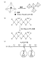
- FIG. 1 is an explanatory diagram relating to an X-type zeolite used as the radioactive iodine adsorbent of the present invention.
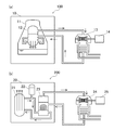
- FIG. 2 is a schematic configuration diagram of a nuclear reactor facility.
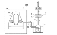
- FIG. 3 is a schematic configuration diagram when the radioactive iodine adsorbent according to the first embodiment is arranged in a boiling water reactor.
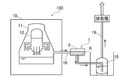
- FIG. 4 is a schematic configuration diagram when the radioactive iodine adsorbent according to the second embodiment is arranged in a boiling water reactor.
- FIG. 5 is a schematic configuration diagram when the radioactive iodine adsorbent according to the third embodiment is arranged in a boiling water reactor.
- FIG. 1 is an explanatory diagram relating to an X-type zeolite used as the radioactive iodine adsorbent of the present invention.
- FIG. 2 is a schematic configuration diagram of a nuclear reactor facility.
- FIG. 3 is a schematic configuration diagram when the radio
- FIG. 6 is a schematic configuration diagram when the radioactive iodine adsorbent according to the fourth embodiment is arranged in a pressurized water reactor.
- FIG. 7 is a graph showing changes in temperature of the radioactive iodine adsorbent.
- radioactive iodine adsorbent and the method for treating radioactive iodine of the present invention will be described with reference to FIGS.
- the present invention is not intended to be limited to the configuration described below.
- FIG. 1 is an explanatory diagram relating to zeolite constituting the radioactive iodine adsorbent of the present invention.
- FIG. 1A is a schematic diagram of the crystal structure of zeolite
- FIG. 1B is an explanatory diagram of a reaction in which sodium sites of 13X zeolite are replaced with silver.
- FIG.1 (c) is explanatory drawing that the size of a pore diameter becomes small as a result of substituting the sodium site of 13X type zeolite with silver. As shown in FIG.
- zeolite is a kind of silicate, and the basic unit of the structure is (SiO 4 ) 4- and (AlO 4 ) 5- having a tetrahedral structure.
- Crystal structures are formed by three-dimensional connection. Various crystal structures are formed depending on the form of connection of the basic units, and each formed crystal structure has a unique uniform pore diameter. Since it has this uniform pore size, the zeolite has characteristics such as molecular sieve, adsorption, and ion exchange ability.
- the radioactive iodine adsorbent of the present invention 13X type zeolite which is a kind of X type zeolite is used.
- 13X type zeolite is a zeolite widely used industrially, and its composition is Na 86 [(AlO 2 ) 86 (SiO 2 ) 106 ] ⁇ 276H 2 O.
- the radioactive iodine adsorbent of the present invention is prepared by ion exchange of sodium sites, which are ion exchange sites of 13X zeolite, with silver.
- the silver ion exchange rate of the radioactive iodine adsorbent is 97% or more, preferably 98% or more.
- the ion exchange site of the X-type zeolite is not ion exchanged with a substance other than silver. That is, in the radioactive iodine adsorbent of the present invention, substantially all sodium sites in the 13X zeolite are ion-exchanged with silver. Because of such a high ion exchange rate, the radioactive iodine adsorbent of the present invention has an adsorbability much superior to conventional radioactive iodine adsorbents. By the way, when the sodium site in 13X type zeolite is ion-exchanged with silver, the size of the pore diameter becomes smaller than that of the original 13X type zeolite.
- the 13X zeolite prepared as described above was found to be effective for hydrogen adsorption, and was conceived to be used as a radioactive iodine adsorbent. That is, as shown in FIG. 1 (c), the pore diameter (about 0.4 nm) of the 13X zeolite having sodium sites before being ion-exchanged with silver is a hydrogen molecule (molecular diameter: about 0.29 nm). Although the size is too large for trapping, ion exchange of sodium sites with silver results in an optimal pore size (approximately 0.29 nm) in which hydrogen molecules fit snugly. As a result, it was found that the 13X zeolite ion-exchanged with silver can adsorb not only radioactive iodine but also hydrogen molecules with high efficiency and efficiency.
- the silver component ratio is 36% by weight or more in a dry state
- the particle size is 10 ⁇ 20 mesh (JIS K 1474-4-6)
- the hardness is preferably 94% or more (JIS K 1474-4-7)
- the water content is preferably 12% by weight or less when the weight loss after drying for 3 hours at 150 ° C.
- the particle size “10 ⁇ 20 mesh” means that the particle passes through the 10 mesh sieve but does not pass through the 20 mesh sieve, that is, the particle size is 10 to 20 mesh.
- the radioactive iodine adsorbent is prepared under such conditions, the excellent hydrogen molecule adsorbing ability can be exhibited more effectively. Further, since the radioactive iodine adsorbent is exposed to a harsh environment (high temperature, high pressure, high humidity), a certain degree of high particle strength is required. Therefore, the radioactive iodine adsorbent according to the present invention is preferably adjusted so that the degree of wear is 3% or less (ASTM D-4058). Thereby, even if it puts on severe conditions, such as a filter vent, a radioactive iodine adsorption agent can maintain the particle shape, and can continue exhibiting high hydrogen molecule adsorption ability.
- FIG. 2 is a schematic configuration diagram of a nuclear reactor facility
- FIG. 2 (a) is a schematic configuration diagram of a boiling water reactor (BWR) 100
- FIG. 2 (b) is a pressurized water reactor (PWR) 200.
- FIG. 2 (b) is a pressurized water reactor (PWR) 200.
- FIG. 2 In Japan, two types of reactor facilities are employed: a boiling water reactor (BWR) and a pressurized water reactor (PWR).
- the nuclear reactor equipment is mainly composed of a reactor building, a reactor containment vessel, a reactor pressure vessel, a turbine, and a generator.
- the boiling water reactor 100 is comprised from the reactor building 10, the reactor containment vessel 11, the reactor pressure vessel 12, the turbine 13, and the generator 14, as shown to Fig.2 (a).
- water is boiled in the reactor pressure vessel 12, and the generated steam is sent to the turbine 13 as indicated by solid arrows in FIG. 2, and the water in the reactor is regenerated as indicated by broken arrows. Circulated. Then, the steam directly turns the turbine 13 and generates electricity by the generator 14.
- the reactor containment vessel 20 is composed of a reactor pressure vessel 21, a pressurizer 22, and a steam generator 23.
- the water in the reactor containment vessel 20 is always kept at a high pressure so that it does not boil even at high temperatures. Then, using the steam generator 23, water other than the water flowing in the reactor (broken arrows in FIG. 2B) is changed to steam (solid arrows in FIG. 2B), and the steam is used for the turbine 24. To generate electricity by the generator 25.
- a method for treating radioactive iodine using a radioactive iodine adsorbent will be described for the boiling water reactor shown in FIG.
- FIG. 3 is a schematic configuration diagram when the radioactive iodine treatment unit 1 containing the radioactive iodine adsorbent K according to the first embodiment of the present invention is disposed in the boiling water reactor 100.
- a description will be given of a radioactive iodine treatment method that assumes a case where an abnormal situation occurs due to an accident or the like in a nuclear reactor.
- a filter vent 15 is installed outside the reactor building 10 in case an accident occurs in the nuclear reactor and the reactor containment vessel 11 is damaged.
- the filter vent 15 is formed through the pipe 16 so that steam from the reactor containment vessel 11 is indicated by a solid arrow in FIG.
- the radioactive iodine treatment unit 1 includes a case 2 that houses a radioactive iodine adsorbent K, and is disposed so as to be connected to the filter vent 15.
- the case 2 is preferably made of a material having heat resistance and corrosion resistance because the steam and gas that have passed through the reactor containment vessel 11 and the filter vent 15 flow therethrough. Examples of the material of the case 2 include stainless steel, and an aluminum alloy or the like can also be used.
- the case 2 needs to have air permeability so that vapor and gas can flow through the radioactive iodine adsorbent K. For this reason, the case 2 is provided with a plurality of minute holes.
- the radioactive iodine adsorbent K is filled in such a manner that the filling density is adjusted to 1.0 g / ml or more, preferably 1.2 g / ml or more (filling step). With such a packing density, the adsorption effect of the radioactive iodine adsorbent K is optimally exhibited.
- nuclear reactor facilities require utmost safety, it is desirable that human work be performed as easily and as quickly as possible.
- the radioactive iodine treatment unit 1 since the radioactive iodine treatment unit 1 has a simple configuration as described above, when the adsorption effect of the radioactive iodine adsorbent K becomes weak, the radioactive iodine adsorbent K is taken out from the case 2 and the new radioactive iodine adsorbent is taken.
- the simple work of simply replacing the agent K can be done. Therefore, the burden on the worker can be reduced, and safety can be ensured.
- steam flows through the radioactive iodine adsorption agent K with which case 2 of the radioactive iodine process part 1 is filled (flowing process).
- the radioactive iodine adsorbent K has a pore diameter suitable for hydrogen molecules, and is filled in the case 2 having air permeability, so that it is included in the vapor flowing through the radioactive iodine treatment unit 1. Effectively removes hydrogen.
- suction of radioactive iodine and hydrogen was removed is exhausted out of a nuclear reactor facility from an exhaust pipe.
- the steam flowing through the radioactive iodine treatment unit 1 is superheated steam having a temperature of 100 ° C.
- the residence time during which the steam flowing through the radioactive iodine treatment unit 1 stays in the case 2 is set to 0.06 seconds or more.
- the radioactive iodine process part 1 was arrange
- the radioactive iodine process part 1 is installed between the filter vent 15 and the nuclear reactor containment vessel 11.
- the steam discharged from the reactor containment vessel 11 is sent to the radioactive iodine treatment unit 1 through the pipe 16 as shown by the solid line arrow in FIG. That is, before the processing by the filter vent 15, the radioactive iodine and hydrogen are adsorbed by the radioactive iodine processing unit 1.
- the radioactive iodine adsorbent K of the present invention is a steam under severe conditions such as superheated steam heated until the temperature of the steam flowing through the case 2 reaches 100 ° C. or higher, radioactive iodine and hydrogen Can be effectively adsorbed and removed. For this reason, the vapor
- the filter vent 15 is constructed with a large amount of money, there is a risk of aging if it is overused. Therefore, if the radioactive iodine treatment method according to the present invention is executed in advance in the stage prior to the filter vent 15, the use period of the filter vent 15 is extended, and it becomes possible to continue operating for a long period of time.
- the radioactive iodine treatment unit 1 is installed between the reactor pressure vessel 12 and the turbine 13, and radioactive iodine is adsorbed and hydrogen is removed before the steam is sent to the turbine 13. This can be done with the adsorbent K. By installing in this way, it is possible to turn the turbine 13 with steam in a safe state, and it is possible to avoid the danger caused by radioactive iodine or hydrogen.
- the first embodiment to the third embodiment are all embodiments for a boiling water reactor, but the radioactive iodine adsorbent K and the radioactive iodine treatment method of the present invention are applied to a pressurized water reactor (PWR). Is also applicable.
- the pressurized water reactor 200 is a nuclear reactor that is safer than a boiling water reactor and has improved maintainability because water containing radioactive materials is not directly sent to the turbine 24. is there.
- the nuclear reactor is a facility that handles very dangerous materials such as nuclear fuel, it is necessary to strictly manage the crisis.
- the radioactive iodine treatment unit 1 can be installed at a position in the middle of sending steam from the steam generator 23 to the turbine 24.
- the radioactive iodine treatment unit 1 is installed only adjacent to the filter vent, or the reactor containment vessel and the filter vent (Not shown).
- Example 1 As Example 1, an adsorption test for radioactive iodine was performed by the radioactive iodine treatment method of the present invention.
- the humidity is then set to 95%, the temperature is 130 ° C., the pressure is 399 KPa, 1.75 mg / m 3 of methyl iodide (CH 3 131 I), and the linear velocity is 20 cm / second and 41 cm.
- the thickness of various radioactive iodine adsorbents was measured for the residence time of the vapor in the case and the adsorption effect of methyl iodide. The measurement results are shown in Table 1.
- Example 2 the thickness of the radioactive iodine adsorbent prepared in Example 1 is 5.0 cm, and the linear velocity is 46 cm for a vapor containing methyl iodide (CH 3 I) having a pressure of 101 KPa and 17 mg / m 3.
- CH 3 I methyl iodide
- Example 3 the radioactive iodine adsorbent prepared in Example 1 was filtered so as to be 100 cm ⁇ 83 cm, the radioactive iodine adsorbent thickness was 26 mm, and the mass was 26 kg, and the pressure was 101 KPa, 0.608 mg / m 3.
- CH 3 I vapor containing methyl iodide
- Table 3 shows the measurement results.
- Example 3 unlike Example 1 and Example 2, the adsorption rate was measured in a form close to the form when the radioactive iodine adsorbent was actually used. From the results of Table 3, it can be seen that in such a form, the adsorption rate of methyl iodide is still high even at a high temperature of 150 ° C. when the temperature of the vapor is increased, and the radioactive iodine adsorbent of the present invention is practically used. It was shown to have a sex.
- Example 4 the radioactive iodine adsorbent prepared in Example 1 had a pressure of 103 KPa, a temperature of 66 ° C., a linear velocity of 20.3 cm / sec, 1.75 mg / m 3 of methyl iodide (CH 3 With respect to the vapor containing 131 I), when the humidity was 70%, the adsorption effect of methyl iodide for each thickness of the radioactive iodine adsorbent was measured. Table 4 shows the measurement results.
- Example 5 the radioactive iodine adsorbent prepared in Example 1 has a pressure of 103 KPa, a linear velocity of 20.3 cm / sec, and 1.75 mg / m 3 of methyl iodide (CH 3 131 I).
- CH 3 131 I methyl iodide
- Example 6 the radioactive iodine adsorbent prepared in Example 1 has a pressure of 101 KPa, a linear velocity of 20 cm / second, a radioactive iodine adsorbent thickness of 5.0 cm, a residence time of 0.25 seconds, The adsorption effect of methyl iodide at each temperature under dry condition was measured with respect to steam containing .75 mg / m 3 of methyl iodide (CH 3 131 I). Table 6 shows the measurement results.
- Example 7 the radioactive iodine adsorbent prepared in Example 1 has a pressure of 101 KPa, a linear velocity of 20 cm / second, a radioactive iodine adsorbent thickness of 5.0 cm, a residence time of 0.25 seconds, The adsorption effect of methyl iodide at each humidity at a temperature of 80 ° C. was measured on a vapor containing .75 mg / m 3 of methyl iodide (CH 3 131 I). Table 7 shows the measurement results.
- Example 8 With respect to the radioactive iodine adsorbent prepared in Example 1, the pressure was 104 KPa, the linear velocity was 20 cm / sec, and the vapor containing 75 mg / m 3 of iodine ( 131 I) was used under dry atmospheric pressure. The adsorption effect of methyl iodide on the thickness and temperature of the radioactive iodine adsorbent was measured. Table 8 shows the measurement results.
- Example 9 In Example 9, with respect to the radioactive iodine adsorbent prepared in Example 1, the hydrogen adsorption effect when the thickness of the radioactive iodine adsorbent was 5 cm was measured. Table 9 shows the measurement results.
- the radioactive iodine adsorbent of the present invention is a high-performance adsorbent capable of adsorbing hydrogen in a stable state even at high temperatures.
- Example 10 the radioactive iodine adsorbent prepared in Example 1 was allowed to flow through the steam having a hydrogen content of 3% with the temperature set at 136 ° C., and the hydrogen content after the flow was 0.
- the measurement result measured about the temperature rise of the radioactive iodine adsorbent when it was 5% or less is shown in the graph of FIG.
- the radioactive iodine adsorbent according to the present invention and the radioactive iodine treatment method of the present configuration are very excellent in adsorption effect even at high temperature, high pressure, and high humidity steam. It was shown to exert. It was also shown to have a highly efficient adsorption effect in a short time. Furthermore, from the results of Example 9 and Example 10, it was found that not only radioactive iodine but also hydrogen was adsorbed with high efficiency and efficiency.
- the radioactive iodine adsorbent and the radioactive iodine treatment method of the present invention are very effective in avoiding dangers such as leakage and scattering of radioactive iodine and nuclear accidents in the nuclear reactor facility.
Landscapes
- Chemical & Material Sciences (AREA)
- Engineering & Computer Science (AREA)
- Physics & Mathematics (AREA)
- Analytical Chemistry (AREA)
- Chemical Kinetics & Catalysis (AREA)
- Organic Chemistry (AREA)
- High Energy & Nuclear Physics (AREA)
- General Engineering & Computer Science (AREA)
- Plasma & Fusion (AREA)
- Environmental & Geological Engineering (AREA)
- Emergency Management (AREA)
- Inorganic Chemistry (AREA)
- Business, Economics & Management (AREA)
- Health & Medical Sciences (AREA)
- Biomedical Technology (AREA)
- General Chemical & Material Sciences (AREA)
- Oil, Petroleum & Natural Gas (AREA)
- Solid-Sorbent Or Filter-Aiding Compositions (AREA)
- Treating Waste Gases (AREA)
- Structure Of Emergency Protection For Nuclear Reactors (AREA)
- Silicates, Zeolites, And Molecular Sieves (AREA)
Abstract
Description
また、原子力施設において、原子炉事故等の異常事態が発生すると、放射性ヨウ素を含む大量の放射性物質が広範囲に飛散するため、原子炉事故は未然に防止しなければならない。そこで、原子炉に異常事態が発生した場合、原子炉の内部圧力を減圧するフィルタベントを原子炉建屋に設置する計画が進められている。ところが、上記の特許文献1及び特許文献2に記載の放射性ヨウ素吸着剤は、フィルタベント等が必要な異常事態に対応することは想定していない。そのため、異常事態が発生した場合にも使用可能な放射性ヨウ素吸着剤や、そのような放射性ヨウ素吸着剤を用いた工程について、さらなる研究開発が必要である。また、原子炉事故は、原子炉内で発生する水素が原因の一つとされているが、この水素を低減することについて、特許文献1及び特許文献2では何ら記載されていない。
X型ゼオライトを造粒してなる放射性ヨウ素吸着剤であって、
前記X型ゼオライトが有するイオン交換サイトを銀で置換することにより、当該X型ゼオライトの微細孔のサイズを水素分子のサイズに適合させてあり、
銀成分の割合が乾燥状態下で36重量%以上であり、粒子のサイズが10×20meshであり、硬度が94%以上であり、150℃下において3時間乾燥減量したときの水分含有量が12重量%以下であることにある。
本発明に係る放射性ヨウ素吸着剤では、ゼオライトの中でも比較的大きな細孔径を有するX型ゼオライトを用いており、X型ゼオライトのイオン交換サイトに存在するナトリウムを銀で置換する。これによって、放射性ヨウ素をヨウ化銀として吸着することができる。従って、原子炉事故のような異常事態が起こった場合であっても、放射性ヨウ素の原子炉外部への飛散を防止できる。
また、X型ゼオライトのナトリウムを銀で置換することにより、X型ゼオライトの微細孔のサイズを水素分子のサイズに適合させてあり、銀成分の割合が乾燥状態下で36重量%以上であり、粒子のサイズが10×20meshであり、硬度が94%以上であり、150℃下において3時間乾燥減量したときの水分含有量が12重量%以下であるため、水素分子を効率的に捉えることができるようになる。これにより、原子炉事故等で水素が発生する事態となっても、本発明の放射性ヨウ素吸着剤を用いれば水素を除去することが可能となり、原子炉事故を未然に回避することができる。
前記X型ゼオライトが有するイオン交換サイトの97%以上が、銀で置換されていることが好ましい。
前記X型ゼオライトが有するイオン交換サイトは、銀以外の物質で置換されていないことが好ましい。
原子力施設から排出される蒸気に含まれる放射性ヨウ素を処理する放射性ヨウ素の処理方法であって、
上記の何れか一に記載の放射性ヨウ素吸着剤を、通気性を備えたケースに充填する充填工程と、
前記放射性ヨウ素吸着剤が充填されたケースに、前記原子力施設から排出される蒸気を通流させる通流工程と、
を包含することにある。
放射性ヨウ素の処理方法を実行するタイミングとして、例えば、フィルタベントによる処理後が挙げられる。フィルタベントとは、原子炉に異常事態が発生し、原子炉事故や、それに伴う放射性ヨウ素の漏洩・飛散を未然に防止するため、原子炉内の高圧の蒸気を原子炉建屋外へ排出する操作である。フィルタベントの後に本発明に係る放射性ヨウ素処理方法を行えば、フィルタベントによって排出された高圧蒸気中の放射性ヨウ素や水素を吸着し、確実に除去することが可能となる。これによって、放射性ヨウ素の飛散や原子炉事故の危険性を未然に回避することができる。
前記原子力施設から排出される蒸気は、水素分子を含むことが好ましい。
前記原子力施設から排出される蒸気は、100℃以上の温度を有する過熱蒸気であることが好ましい。
前記充填工程において、前記放射性ヨウ素吸着剤の充填密度を1.0g/ml以上に調整することが好ましい。
前記通流工程において、前記放射性ヨウ素吸着剤が充填されたケース内における前記蒸気の滞留時間を0.06秒以上に設定することが好ましい。
前記通流工程において、前記蒸気の圧力は399KPa以上であることが好ましい。
前記通流工程において、前記放射性ヨウ素吸着剤が充填されたケース内の湿度は95%以上であることが好ましい。
初めに、本発明の放射性ヨウ素吸着剤に使用するX型ゼオライトについて説明する。図1は、本発明の放射性ヨウ素吸着剤を構成するゼオライトに関する説明図である。図1(a)は、ゼオライトの結晶構造の模式図であり、図1(b)は、13X型ゼオライトのナトリウムサイトが銀で置換される反応の説明図である。図1(c)は、13X型ゼオライトのナトリウムサイトを銀で置換した結果、細孔径のサイズが小さくなることの説明図である。
図1(a)に示すように、ゼオライトはケイ酸塩の一種で、構造の基本単位は四面体構造の(SiO4)4-及び(AlO4)5-であり、この基本単位が次々と三次元的に連結して結晶構造を形成する。基本単位の連結の形式によって種々の結晶構造が形成され、形成される結晶構造ごとに固有の均一な細孔径を有する。この均一な細孔径を有するため、ゼオライトには分子篩や吸着、イオン交換能といった特性が備わることとなる。
ところで、13X型ゼオライト中のナトリウムサイトが銀でイオン交換されると、元の13X型ゼオライトよりも細孔径のサイズが小さくなるが、本発明者らは鋭意研究の結果、細孔径のサイズが小さくなるように調整した13X型ゼオライトは、水素の吸着に有効であることを見出し、これを放射性ヨウ素吸着剤として利用することに想到した。すなわち、図1(c)に示すように、銀でイオン交換される前のナトリウムサイトを有する13X型ゼオライトの細孔径(約0.4nm)は、水素分子(分子径:約0.29nm)を捕捉するには大き過ぎるサイズであるが、ナトリウムサイトを銀でイオン交換すると、水素分子がぴったりと収まる最適な細孔径(約0.29nm)となる。その結果、銀でイオン交換された13X型ゼオライトは、放射性ヨウ素だけでなく、水素分子についても高効率で効果的に吸着することが可能となることが判明した。
上記のように調製した放射性ヨウ素吸着剤を用いた放射性ヨウ素処理方法について説明する前に、代表的な原子力発電の構造を図2に基づいて説明する。図2は、原子炉設備の概略構成図であり、図2(a)は、沸騰水型炉(BWR)100の概略構成図であり、図2(b)は、加圧水型炉(PWR)200の概略構成図である。日本国内には原子炉施設として沸騰水型炉(BWR)、及び加圧水型炉(PWR)の2種類の型式が採用されている。原子炉設備は、主に、原子炉建屋、原子炉格納容器、原子炉圧力容器、タービン、及び発電機から構成されている。沸騰水型炉100は、図2(a)に示すように、原子炉建屋10、原子炉格納容器11、原子炉圧力容器12、タービン13、及び発電機14から構成されている。沸騰水型炉100では、原子炉圧力容器12で水を沸騰させ、発生した蒸気は図2中に実線矢印で示すようにタービン13に送られ、原子炉の水は破線矢印で示すように再循環される。そして、この蒸気が直接タービン13を回し、発電機14で電気を発生させる。一方、加圧水型炉200は、図2(b)に示すように、原子炉格納容器20が、原子炉圧力容器21、加圧器22、及び蒸気発生器23から構成されており、加圧器22によって原子炉格納容器20内の水を常に高圧にして高温でも沸騰しないように制御している。そして、蒸気発生器23を使って原子炉内を流れる水(図2(b)の破線矢印)とは別の水を蒸気(図2(b)の実線矢印)にして、この蒸気によってタービン24を回して発電機25によって電気を発生させる。以下の第一実施形態においては、図2(a)に示した沸騰水型炉について、放射性ヨウ素吸着剤を用いた放射性ヨウ素の処理方法を説明する。
〔充填工程〕
図3は、本発明の第一実施形態に係る放射性ヨウ素吸着剤Kを収納した放射性ヨウ素処理部1を沸騰水型炉100に配置したときの概略構成図である。第一実施形態においては、原子炉が事故等による異常事態が起こった場合を想定した放射性ヨウ素処理方法について説明する。原子炉に事故が起こり、原子炉格納容器11が損傷した場合に備えて原子炉建屋10の外側にフィルタベント15が設置されている。フィルタベント15は、例えば、原子炉格納容器11が事故により損傷した場合、内部圧力を下げるために原子炉格納容器11からの蒸気が図3の実線矢印で示すように、配管16を通じてフィルタベント15へと送られ、蒸気中の放射性ヨウ素を捕集し微量化して、原子炉建屋10の外へ排気するための設備である。放射性ヨウ素処理部1は、図3に示すように、放射性ヨウ素吸着剤Kを収納するケース2から構成されており、フィルタベント15に接続するように配置される。後に詳述するが、ケース2は原子炉格納容器11やフィルタベント15を通過した蒸気やガスが通流するため、耐熱性や耐蝕性を有する材料で構成することが好ましい。ケース2の材質として、例えば、ステンレス鋼が挙げられ、その他にアルミニウム合金等を使用することも可能である。ケース2は、蒸気やガスが放射性ヨウ素吸着剤Kを通流できるよう、通気性を備えておく必要がある。そのため、ケース2には微小な孔が複数設けられている。このようなケース2の中に放射性ヨウ素吸着剤Kを充填密度が1.0g/ml以上、好ましくは1.2g/ml以上となるように調整して充填する(充填工程)。このような充填密度であれば、放射性ヨウ素吸着剤Kの吸着効果が最適に発揮される。また、原子炉施設は安全面に最大限の注意が必要であるため、人による作業は出来る限り簡単且つ短時間で行うことが望まれる。この点、放射性ヨウ素処理部1は上記のとおり簡単な構成であるから、放射性ヨウ素吸着剤Kの吸着効果が弱くなってきたとき、ケース2から放射性ヨウ素吸着剤Kを取り出して新品の放射性ヨウ素吸着剤Kに取り替えるだけという単純な作業で済ませることができる。そのため、作業員の負担を軽減することができ、安全性を確保することができる。
上記のように、フィルタベント15によって放射性ヨウ素の量を低減することはできるが、放射性ヨウ素は人体や環境に重大な悪影響を及ぼすため、確実に除去した状態で原子炉建屋10から排気する必要がある。そこで、本発明の放射性ヨウ素吸着剤Kを用いて確実に放射性ヨウ素の除去を行う。図3に示すように、フィルタベント15によって処理された蒸気は、図3の実線矢印で示すように、配管16を通じて放射性ヨウ素処理部1に送られる。そして、放射性ヨウ素処理部1のケース2に充填されている放射性ヨウ素吸着剤Kに蒸気が通流する(通流工程)。放射性ヨウ素吸着剤Kは、前述したように水素分子に適した細孔径を有しており、通気性を備えたケース2に充填されているため、放射性ヨウ素処理部1を通流する蒸気に含まれる水素を効果的に除去する。そして、放射性ヨウ素の吸着、及び水素が除去された後の蒸気は、排気筒から原子炉施設外へ排気される。ここで、放射性ヨウ素処理部1を通流する蒸気は、100℃以上の温度を有する過熱蒸気であり、その圧力が399KPa以上であり、さらにケース2内の湿度が95%以上という苛酷な状況下であっても、放射性ヨウ素吸着剤Kによって放射性ヨウ素及び水素が除去される。さらに、本発明の放射性ヨウ素処理方法では、放射性ヨウ素処理部1を通流する蒸気がケース2内に滞留する滞留時間は0.06秒以上に設定されている。原子炉格納容器11が損傷したとき、放射性ヨウ素の漏洩・飛散や原子炉事故が起こらないように一刻も早く対処しなければならない。そのため、フィルタベント15による処理や、放射性ヨウ素の処理をできるだけ短時間で完了させることが必要である。ここで、本発明においては、上記のようにケース2内における蒸気の滞留時間が非常に短時間であるため、緊急事態に対して従来の放射性ヨウ素処理方法よりもはるかに早く放射性ヨウ素の吸着、及び水素の除去を完了させることができ、安全性の確保に非常に有効な方法となる。
上記の第一実施形態では、放射性ヨウ素処理部1を沸騰水型炉100に対し、原子炉格納容器11とは直接隣接しないように配置した。これに対し、第二実施形態では、図4に示すように、放射性ヨウ素処理部1をフィルタベント15と原子炉格納容器11との間に設置する。この場合、原子炉格納容器11から排出される蒸気は、図4の実線矢印で示すように、配管16を通じて放射性ヨウ素処理部1に送られる。つまり、フィルタベント15による処理の前に、放射性ヨウ素及び水素の吸着を放射性ヨウ素処理部1にて行う。本発明の放射性ヨウ素吸着剤Kは、ケース2内を通流する蒸気の温度が100℃以上になるまで過熱された過熱蒸気である等の苛酷な条件の蒸気であっても、放射性ヨウ素及び水素を効果的に吸着及び除去することができる。このため、原子炉格納容器11から排出された蒸気を直接放射性ヨウ素処理部1に送り、効果的に処理することができる。このように、フィルタベント15へ蒸気を送る前に放射性ヨウ素処理部1にて、放射性ヨウ素の吸着、及び水素の除去を行うことにより、この後のフィルタベント15での負担を軽減するとともに、フィルタベント15による処理をスムーズに行うことが可能となる。また、フィルタベント15は多額の費用を掛けて建設されるものであるから、酷使すると老朽化を早めてしまう虞がある。そのため、フィルタベント15の前段階において、本発明に係る放射性ヨウ素処理方法を予め実行しておけば、フィルタベント15の使用期間が延長され、長期間に亘って稼動し続けることが可能となる。
上記の第一実施形態及び第二実施形態では、原子炉施設(沸騰水型炉100)が事故等に遭った場合の緊急事態を想定した実施形態であったが、本発明の放射性ヨウ素吸着剤K及び放射性ヨウ素処理方法は、緊急事態の場合以外においても用いることができる。特に沸騰水型炉100は、上記のとおり、原子炉圧力容器12の蒸気が直接タービン13に送られるため、放射性ヨウ素や水素の量を厳重に管理し、確実に安全な状態にしておかなければならない。そこで、図5に示すように、原子炉圧力容器12とタービン13との間に放射性ヨウ素処理部1を設置し、タービン13に蒸気を送る前に放射性ヨウ素の吸着、及び水素の除去を放射性ヨウ素吸着剤Kによって行うことができる。このように設置することで、安全な状態の蒸気によりタービン13を回すことができ、放射性ヨウ素や水素に起因する危険性を回避することが可能となる。
上記の第一実施形態ないし第三実施形態は、いずれも沸騰水型炉についての実施形態であったが、本発明の放射性ヨウ素吸着剤K及び放射性ヨウ素処理方法は、加圧水型炉(PWR)においても適用可能である。図2(b)に示すように、加圧水型炉200は、放射性物質を含む水がタービン24に直接送られないため、沸騰水型炉よりも安全でありメンテナンス性が向上している原子炉である。しかし、原子炉は核燃料という非常に危険な物質を扱う設備であるため、危機管理は厳重に行う必要がある。そのため、この加圧水型炉に対しても、放射性ヨウ素吸着剤Kを用いれば緊急事態に対応できる。加圧水型炉200に放射性ヨウ素吸着剤Kを用いる場合、例えば、図6に示すように、蒸気発生器23からタービン24に蒸気を送る途中の位置に放射性ヨウ素処理部1を設置することができる。また、沸騰水型炉と同様に、事故等で原子炉が損傷した場合の対策として、放射性ヨウ素処理部1をフィルタベントにのみ隣接するように設置することや、原子炉格納容器とフィルタベントとの間に設置することもできる(図示せず)。
実施例1として、本発明の放射性ヨウ素処理方法により、放射性ヨウ素の吸着試験を行った。

実施例2では、実施例1で調製した放射性ヨウ素吸着剤の厚みを5.0cmとし、圧力が101KPa、17mg/m3のヨウ化メチル(CH3I)を含む蒸気に対し、線速度を46cm/秒に設定したときの各温度におけるヨウ化メチルの吸着効果について測定した。測定結果を表2に示す。

実施例3では、実施例1で調製した放射性ヨウ素吸着剤について、100cm×83cm、放射性ヨウ素吸着剤厚みが26mm、質量が26kgであるようにフィルター加工し、圧力が101KPa、0.608mg/m3のヨウ化メチル(CH3I)を含む蒸気に対し、線速度を20cm/秒に設定したときの各温度におけるヨウ化メチルの吸着効果について測定した。測定結果を表3に示す。

実施例4では、実施例1で調製した放射性ヨウ素吸着剤について、圧力が103KPa、温度が66℃、線速度が20.3cm/秒であり、1.75mg/m3のヨウ化メチル(CH3 131I)を含む蒸気に対し、湿度が70%のとき、放射性ヨウ素吸着剤の厚みごとのヨウ化メチルの吸着効果について測定した。測定結果を表4に示す。

実施例5では、実施例1で調製した放射性ヨウ素吸着剤について、圧力が103KPa、線速度が20.3cm/秒であり、1.75mg/m3のヨウ化メチル(CH3 131I)を含む蒸気に対し、湿度が95%のとき、放射性ヨウ素吸着剤の厚みと温度に関するヨウ化メチルの吸着効果について測定した。測定結果を表5に示す。
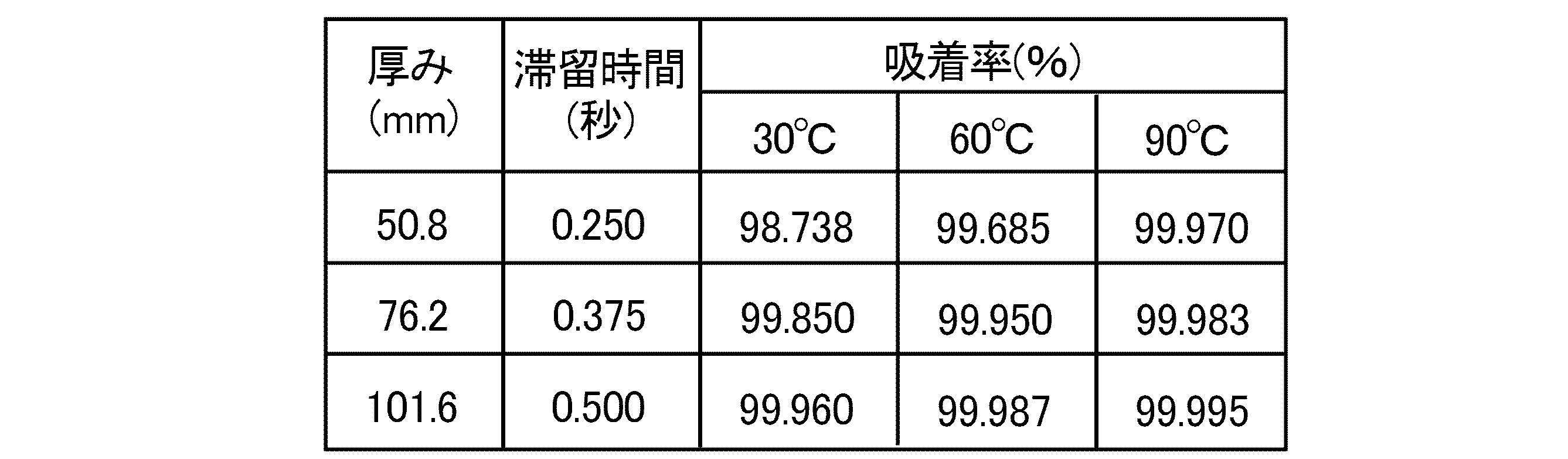
実施例6では、実施例1で調製した放射性ヨウ素吸着剤について、圧力が101KPa、線速度が20cm/秒、放射性ヨウ素吸着剤の厚みが5.0cm、滞留時間が0.25秒であり、1.75mg/m3のヨウ化メチル(CH3 131I)を含む蒸気に対し、乾燥状態下の各温度におけるヨウ化メチルの吸着効果について測定した。測定結果を表6に示す。

実施例7では、実施例1で調製した放射性ヨウ素吸着剤について、圧力が101KPa、線速度が20cm/秒、放射性ヨウ素吸着剤の厚みが5.0cm、滞留時間が0.25秒であり、1.75mg/m3のヨウ化メチル(CH3 131I)を含む蒸気に対し、温度が80℃のときの各湿度におけるヨウ化メチルの吸着効果について測定した。測定結果を表7に示す。

実施例8では、実施例1で調製した放射性ヨウ素吸着剤について、圧力が104KPa、線速度が20cm/秒であり、75mg/m3のヨウ素(131I)を含む蒸気に対し、乾燥大気圧下において、放射性ヨウ素吸着剤の厚みと温度に関するヨウ化メチルの吸着効果について測定した。測定結果を表8に示す。

実施例9では、実施例1で調製した放射性ヨウ素吸着剤について、放射性ヨウ素吸着剤の厚みが5cmであるときの水素の吸着効果について測定した。測定結果を表9に示す。
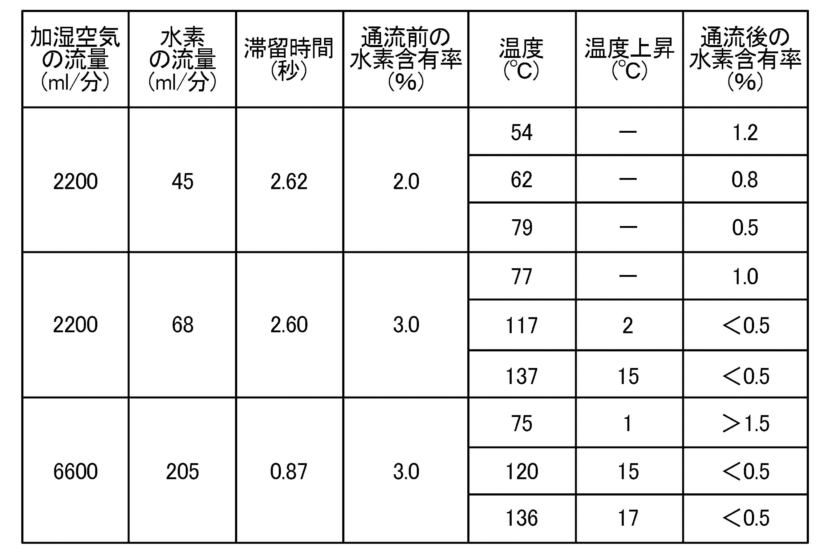
実施例10では、水素含有率が3%である蒸気に対し、温度を136℃に設定し実施例1で調製した放射性ヨウ素吸着剤を通流させて、通流後の水素含有率が0.5%以下であったときの放射性ヨウ素吸着剤の温度上昇について測定した、測定結果を図7のグラフに示す。
2 ケース
10 原子炉建屋
11、20 原子炉格納容器
12、21 原子炉圧力容器
100 沸騰水型炉
200 加圧水型炉
K 放射性ヨウ素吸着剤
Claims (10)
- X型ゼオライトを造粒してなる放射性ヨウ素吸着剤であって、
前記X型ゼオライトが有するイオン交換サイトを銀で置換することにより、当該X型ゼオライトの微細孔のサイズを水素分子のサイズに適合させてあり、
銀成分の割合が乾燥状態下で36重量%以上であり、粒子のサイズが10×20meshであり、硬度が94%以上であり、150℃下において3時間乾燥減量したときの水分含有量が12重量%以下である放射性ヨウ素吸着剤。 - 前記X型ゼオライトが有するイオン交換サイトの97%以上が、銀で置換されている請求項1に記載の放射性ヨウ素吸着剤。
- 前記X型ゼオライトが有するイオン交換サイトは、銀以外の物質で置換されていない請求項1又は2に記載の放射性ヨウ素吸着剤。
- 原子力施設から排出される蒸気に含まれる放射性ヨウ素を処理する放射性ヨウ素の処理方法であって、
請求項1~3の何れか一項に記載の放射性ヨウ素吸着剤を、通気性を備えたケースに充填する充填工程と、
前記放射性ヨウ素吸着剤が充填されたケースに、前記原子力施設から排出される蒸気を通流させる通流工程と、
を包含する放射性ヨウ素の処理方法。 - 前記原子力施設から排出される蒸気は、水素分子を含む請求項4に記載の放射性ヨウ素の処理方法。
- 前記原子力施設から排出される蒸気は、100℃以上の温度を有する過熱蒸気である請求項4又は5に記載の放射性ヨウ素の処理方法。
- 前記充填工程において、前記放射性ヨウ素吸着剤の充填密度を1.0g/ml以上に調整する請求項4~6の何れか一項に記載の放射性ヨウ素の処理方法。
- 前記通流工程において、前記放射性ヨウ素吸着剤が充填されたケース内における前記蒸気の滞留時間を0.06秒以上に設定する請求項4~7の何れか一項に記載の放射性ヨウ素の処理方法。
- 前記通流工程において、前記蒸気の圧力は399KPa以上である請求項4~8の何れか一項に記載の放射性ヨウ素の処理方法。
- 前記通流工程において、前記放射性ヨウ素吸着剤が充填されたケース内の湿度は95%以上である請求項4~9の何れか一項に記載の放射性ヨウ素の処理方法。
Priority Applications (9)
| Application Number | Priority Date | Filing Date | Title |
|---|---|---|---|
| EP14855190.6A EP3062314B1 (en) | 2013-10-23 | 2014-08-22 | Disposal method for radioactive iodine |
| CN201480057522.3A CN105814643B (zh) | 2013-10-23 | 2014-08-22 | 放射性碘吸附剂及放射性碘的处理方法 |
| RU2016119398A RU2620584C1 (ru) | 2013-10-23 | 2014-08-22 | Адсорбент радиоактивного йода и способ обработки радиоактивного йода |
| KR1020167010693A KR101738444B1 (ko) | 2013-10-23 | 2014-08-22 | 방사성 요오드 흡착제, 및 방사성 요오드의 처리 방법 |
| ES14855190T ES2773503T3 (es) | 2013-10-23 | 2014-08-22 | Método de eliminación de yodo radiactivo |
| US15/029,642 US20160247588A1 (en) | 2013-10-23 | 2014-08-22 | Radioactive iodine adsorbent, and method for treating radioactive iodine |
| CA2927657A CA2927657C (en) | 2013-10-23 | 2014-08-22 | Radioactive iodine adsorbent, and method for treating radioactive iodine |
| US15/860,900 US20180190404A1 (en) | 2013-10-23 | 2018-01-03 | Radioactive iodine adsorbent, and method for treating radioactive iodine |
| US17/231,068 US20210304912A1 (en) | 2013-10-23 | 2021-04-15 | Radioactive iodine adsorbent, and method for treating radioactive iodine |
Applications Claiming Priority (2)
| Application Number | Priority Date | Filing Date | Title |
|---|---|---|---|
| JP2013219867A JP5504368B1 (ja) | 2013-10-23 | 2013-10-23 | 放射性ヨウ素吸着剤、及び放射性ヨウ素の処理方法 |
| JP2013-219867 | 2013-10-23 |
Related Child Applications (2)
| Application Number | Title | Priority Date | Filing Date |
|---|---|---|---|
| US15/029,642 A-371-Of-International US20160247588A1 (en) | 2013-10-23 | 2014-08-22 | Radioactive iodine adsorbent, and method for treating radioactive iodine |
| US15/860,900 Division US20180190404A1 (en) | 2013-10-23 | 2018-01-03 | Radioactive iodine adsorbent, and method for treating radioactive iodine |
Publications (1)
| Publication Number | Publication Date |
|---|---|
| WO2015059994A1 true WO2015059994A1 (ja) | 2015-04-30 |
Family
ID=50941836
Family Applications (1)
| Application Number | Title | Priority Date | Filing Date |
|---|---|---|---|
| PCT/JP2014/072011 Ceased WO2015059994A1 (ja) | 2013-10-23 | 2014-08-22 | 放射性ヨウ素吸着剤、及び放射性ヨウ素の処理方法 |
Country Status (11)
| Country | Link |
|---|---|
| US (3) | US20160247588A1 (ja) |
| EP (1) | EP3062314B1 (ja) |
| JP (1) | JP5504368B1 (ja) |
| KR (1) | KR101738444B1 (ja) |
| CN (1) | CN105814643B (ja) |
| CA (1) | CA2927657C (ja) |
| ES (1) | ES2773503T3 (ja) |
| HU (1) | HUE049191T2 (ja) |
| RU (1) | RU2620584C1 (ja) |
| TW (1) | TWI642476B (ja) |
| WO (1) | WO2015059994A1 (ja) |
Cited By (1)
| Publication number | Priority date | Publication date | Assignee | Title |
|---|---|---|---|---|
| JP2020082015A (ja) * | 2018-11-29 | 2020-06-04 | 株式会社コベルコ科研 | 吸着塔およびガス中の揮発性有機化合物の除去装置 |
Families Citing this family (19)
| Publication number | Priority date | Publication date | Assignee | Title |
|---|---|---|---|---|
| JP2016080439A (ja) * | 2014-10-14 | 2016-05-16 | ラサ工業株式会社 | 機能分担フィルタユニット、空気浄化装置、空気浄化機能付き衛生用製品、及び放射性ヨウ素除去装置 |
| EP3270384B1 (en) * | 2015-03-12 | 2021-08-04 | Rasa Industries, Ltd. | Filtration material for filtered venting, use thereof and filtered venting device containing the same |
| JP6238932B2 (ja) * | 2015-06-04 | 2017-11-29 | 株式会社荏原製作所 | ヨウ素化合物吸着剤及びその製造方法並びにヨウ素化合物吸着剤を用いる放射性廃液の処理方法及び装置 |
| WO2017146130A1 (ja) * | 2016-02-26 | 2017-08-31 | 株式会社荏原製作所 | 放射性ヨウ素含有流体の処理方法 |
| EP3421428B1 (en) | 2016-02-26 | 2022-04-13 | Tosoh Corporation | Silver-carrying zeolite molded article |
| WO2018064572A1 (en) * | 2016-09-29 | 2018-04-05 | Elysium Industries Ltd. | Silver chloride waste form and apparatus |
| JP6928928B2 (ja) * | 2016-12-15 | 2021-09-01 | 東洋紡株式会社 | 放射性物質除去フィルタ、それを用いる放射性物質除去フィルタユニット及び放射性物質の除去方法 |
| RU2734626C1 (ru) * | 2017-10-05 | 2020-10-21 | Раса Индастриз, Лтд. | Устройство источника тепла и способ использования серебросодержащего цеолита |
| CN108939811B (zh) * | 2018-08-03 | 2021-05-18 | 中国核动力研究设计院 | 一种气态碘提取方法 |
| CN110496588B (zh) * | 2019-06-20 | 2021-02-09 | 中国科学院长春应用化学研究所 | 一种放射性碘的吸附方法 |
| US11735329B2 (en) | 2019-10-15 | 2023-08-22 | Korea Atomic Energy Research Institute | Radioactive chemical waste treatment apparatus |
| KR102437395B1 (ko) | 2020-08-19 | 2022-08-30 | 한국원자력연구원 | 원자로의 피동형 보호 계통 |
| CN111986828B (zh) * | 2020-08-20 | 2022-12-13 | 中国原子能科学研究院 | 放射性碘废物的方钠石基陶瓷-玻璃双重固化方法 |
| CN112023874A (zh) * | 2020-09-18 | 2020-12-04 | 上海复旭分子筛有限公司 | 用于深度脱除气相介质中碘化物的沸石分子筛吸附剂及其制备方法和应用 |
| KR102369705B1 (ko) * | 2020-09-24 | 2022-03-03 | 한국원자력연구원 | 선박의 피동냉각 설비 및 피동냉각 방법 |
| KR102582425B1 (ko) * | 2021-08-31 | 2023-09-25 | 한국원자력연구원 | 원전이 구비된 선박 |
| US20230083647A1 (en) * | 2021-09-10 | 2023-03-16 | Battelle Energy Alliance, Llc | Reusable structures containing isotopes for simulating radioactive contamination environments, and methods of formation |
| CN116459790B (zh) * | 2023-04-24 | 2024-03-29 | 西华师范大学 | 飞絮纤维负载零价纳米银高效固定气态碘材料的制备方法 |
| CN118236971A (zh) * | 2024-03-11 | 2024-06-25 | 哈尔滨工程大学 | 一种疏水载银沸石及其制备方法和应用 |
Citations (7)
| Publication number | Priority date | Publication date | Assignee | Title |
|---|---|---|---|---|
| US3658467A (en) * | 1969-07-28 | 1972-04-25 | Atomic Energy Commission | System for total iodine retention |
| US4088737A (en) * | 1976-11-02 | 1978-05-09 | The United States Of America As Represented By The United States Department Of Energy | Dry method for recycling iodine-loaded silver zeolite |
| JPS544890A (en) | 1977-06-15 | 1979-01-13 | Hitachi Ltd | Adsorbent |
| JPS60225638A (ja) | 1984-04-25 | 1985-11-09 | Nippon Atom Ind Group Co Ltd | ヨウ素吸着剤 |
| JPH1095611A (ja) * | 1996-09-20 | 1998-04-14 | Nippon Sanso Kk | ガス吸着用ゼオライトおよびその製法ならびにこれを用いたガス吸着分離方法 |
| JP2003020489A (ja) * | 2001-07-05 | 2003-01-24 | Tokyo Gas Co Ltd | 燃料ガスの脱硫装置及び脱硫方法 |
| WO2012147937A1 (ja) * | 2011-04-27 | 2012-11-01 | 株式会社カネカ | イオン交換繊維とその製造方法、水中の化学物質の除去・吸着方法及び水中の化学物質の除去・吸着装置 |
Family Cites Families (11)
| Publication number | Priority date | Publication date | Assignee | Title |
|---|---|---|---|---|
| DE2109146C3 (de) * | 1971-02-26 | 1980-03-20 | Bayer Ag, 5090 Leverkusen | Verfahren zur Entfernung von Jod und Jodverbindungen aus Gasen und Dämpfen und silbernitratimprägnierte Sorptionsmittel zur Durchführung des Verfahrens |
| DE3808742A1 (de) * | 1988-03-16 | 1989-09-28 | Kernforschungsz Karlsruhe | Verfahren zur entfernung von iod und iodverbindungen aus gasen und daempfen mit silberhaltigem zeolith x |
| US5075084A (en) * | 1989-01-21 | 1991-12-24 | Bayer Aktiengesellschaft | Process for the removal of iodine and iodine compounds from hydrogen-containing gases and vapors |
| DE19532366C1 (de) * | 1995-09-01 | 1996-12-05 | Siemens Ag | Vorrichtung und Verfahren zur Inertisierung und zum Venting der Containment-Atmosphäre in einem Kernkraftwerk |
| JP2954881B2 (ja) * | 1996-08-20 | 1999-09-27 | 核燃料サイクル開発機構 | 放射性ヨウ素含有廃棄物の固化方法 |
| RU2161338C2 (ru) * | 1999-02-01 | 2000-12-27 | Государственное предприятие "Ленинградская атомная электростанция им. В.И. Ленина" | Сорбционно-фильтрующая загрузка для очистки воздуха от радиоактивного йода |
| RU2262758C2 (ru) * | 2003-11-24 | 2005-10-20 | Закрытое акционерное общество "Прогресс-Экология" (ЗАО "Прогресс-Экология") | Фильтр для очистки воздуха от радиоактивного йода |
| US7455718B2 (en) * | 2005-06-30 | 2008-11-25 | Praxair Technology, Inc. | Silver-exchanged zeolites and methods of manufacture therefor |
| WO2011152909A2 (en) * | 2010-03-09 | 2011-12-08 | Kurion, Inc. | Isotope-specific separation and vitrification using ion-specific media |
| DE102011056889B3 (de) * | 2011-12-22 | 2013-03-07 | Yit Germany Gmbh | Filtervorrichtung zur Filtration eines mit Aerosolen und/oder gasförmigem Jod beladenen Gasstroms |
| JP5875958B2 (ja) * | 2012-08-29 | 2016-03-02 | 日立Geニュークリア・エナジー株式会社 | 原子力プラントのガス処理設備 |
-
2013
- 2013-10-23 JP JP2013219867A patent/JP5504368B1/ja active Active
-
2014
- 2014-08-22 US US15/029,642 patent/US20160247588A1/en not_active Abandoned
- 2014-08-22 RU RU2016119398A patent/RU2620584C1/ru active
- 2014-08-22 CN CN201480057522.3A patent/CN105814643B/zh active Active
- 2014-08-22 ES ES14855190T patent/ES2773503T3/es active Active
- 2014-08-22 CA CA2927657A patent/CA2927657C/en active Active
- 2014-08-22 HU HUE14855190A patent/HUE049191T2/hu unknown
- 2014-08-22 WO PCT/JP2014/072011 patent/WO2015059994A1/ja not_active Ceased
- 2014-08-22 KR KR1020167010693A patent/KR101738444B1/ko active Active
- 2014-08-22 EP EP14855190.6A patent/EP3062314B1/en active Active
- 2014-08-26 TW TW103129291A patent/TWI642476B/zh active
-
2018
- 2018-01-03 US US15/860,900 patent/US20180190404A1/en not_active Abandoned
-
2021
- 2021-04-15 US US17/231,068 patent/US20210304912A1/en not_active Abandoned
Patent Citations (7)
| Publication number | Priority date | Publication date | Assignee | Title |
|---|---|---|---|---|
| US3658467A (en) * | 1969-07-28 | 1972-04-25 | Atomic Energy Commission | System for total iodine retention |
| US4088737A (en) * | 1976-11-02 | 1978-05-09 | The United States Of America As Represented By The United States Department Of Energy | Dry method for recycling iodine-loaded silver zeolite |
| JPS544890A (en) | 1977-06-15 | 1979-01-13 | Hitachi Ltd | Adsorbent |
| JPS60225638A (ja) | 1984-04-25 | 1985-11-09 | Nippon Atom Ind Group Co Ltd | ヨウ素吸着剤 |
| JPH1095611A (ja) * | 1996-09-20 | 1998-04-14 | Nippon Sanso Kk | ガス吸着用ゼオライトおよびその製法ならびにこれを用いたガス吸着分離方法 |
| JP2003020489A (ja) * | 2001-07-05 | 2003-01-24 | Tokyo Gas Co Ltd | 燃料ガスの脱硫装置及び脱硫方法 |
| WO2012147937A1 (ja) * | 2011-04-27 | 2012-11-01 | 株式会社カネカ | イオン交換繊維とその製造方法、水中の化学物質の除去・吸着方法及び水中の化学物質の除去・吸着装置 |
Non-Patent Citations (1)
| Title |
|---|
| See also references of EP3062314A4 * |
Cited By (2)
| Publication number | Priority date | Publication date | Assignee | Title |
|---|---|---|---|---|
| JP2020082015A (ja) * | 2018-11-29 | 2020-06-04 | 株式会社コベルコ科研 | 吸着塔およびガス中の揮発性有機化合物の除去装置 |
| JP7166152B2 (ja) | 2018-11-29 | 2022-11-07 | 株式会社コベルコ科研 | 吸着塔およびガス中の揮発性有機化合物の除去装置 |
Also Published As
| Publication number | Publication date |
|---|---|
| US20210304912A1 (en) | 2021-09-30 |
| EP3062314A1 (en) | 2016-08-31 |
| EP3062314B1 (en) | 2020-01-22 |
| EP3062314A4 (en) | 2017-07-05 |
| ES2773503T3 (es) | 2020-07-13 |
| CA2927657C (en) | 2017-12-05 |
| US20180190404A1 (en) | 2018-07-05 |
| JP2015081841A (ja) | 2015-04-27 |
| CN105814643B (zh) | 2018-06-08 |
| CA2927657A1 (en) | 2015-04-30 |
| TW201542291A (zh) | 2015-11-16 |
| CN105814643A (zh) | 2016-07-27 |
| RU2620584C1 (ru) | 2017-05-29 |
| US20160247588A1 (en) | 2016-08-25 |
| HUE049191T2 (hu) | 2020-09-28 |
| JP5504368B1 (ja) | 2014-05-28 |
| KR101738444B1 (ko) | 2017-05-22 |
| KR20160060731A (ko) | 2016-05-30 |
| TWI642476B (zh) | 2018-12-01 |
Similar Documents
| Publication | Publication Date | Title |
|---|---|---|
| JP5504368B1 (ja) | 放射性ヨウ素吸着剤、及び放射性ヨウ素の処理方法 | |
| JP6326548B2 (ja) | フィルタベント用充填剤、及びフィルタベント装置 | |
| JP5875958B2 (ja) | 原子力プラントのガス処理設備 | |
| JP6656766B2 (ja) | フィルタベント用充填剤、及びフィルタベント装置 | |
| CN107569969A (zh) | 一种高毒气态污染物高效净化材料及使用装置 | |
| JP7282661B2 (ja) | 浄化装置 | |
| CA3014634C (en) | Treatment method of radioactive iodine-containing fluid | |
| RU2346347C1 (ru) | Сорбент для улавливания летучих форм радиоактивного иода на основе силикагеля | |
| JP2020082015A (ja) | 吸着塔およびガス中の揮発性有機化合物の除去装置 | |
| JP2019064895A (ja) | 再結合装置、及び銀ゼオライトの再結合触媒としての利用方法 | |
| CN117720115A (zh) | 一种银基分子筛的制备方法及其应用 | |
| CN117138747A (zh) | 一种碘吸附材料及其制备方法、应用 |
Legal Events
| Date | Code | Title | Description |
|---|---|---|---|
| 121 | Ep: the epo has been informed by wipo that ep was designated in this application |
Ref document number: 14855190 Country of ref document: EP Kind code of ref document: A1 |
|
| ENP | Entry into the national phase |
Ref document number: 2927657 Country of ref document: CA |
|
| WWE | Wipo information: entry into national phase |
Ref document number: 15029642 Country of ref document: US |
|
| ENP | Entry into the national phase |
Ref document number: 20167010693 Country of ref document: KR Kind code of ref document: A |
|
| NENP | Non-entry into the national phase |
Ref country code: DE |
|
| ENP | Entry into the national phase |
Ref document number: 2016119398 Country of ref document: RU Kind code of ref document: A |
|
| REEP | Request for entry into the european phase |
Ref document number: 2014855190 Country of ref document: EP |
|
| WWE | Wipo information: entry into national phase |
Ref document number: 2014855190 Country of ref document: EP |