WO2015060194A1 - 表示装置 - Google Patents
表示装置 Download PDFInfo
- Publication number
- WO2015060194A1 WO2015060194A1 PCT/JP2014/077561 JP2014077561W WO2015060194A1 WO 2015060194 A1 WO2015060194 A1 WO 2015060194A1 JP 2014077561 W JP2014077561 W JP 2014077561W WO 2015060194 A1 WO2015060194 A1 WO 2015060194A1
- Authority
- WO
- WIPO (PCT)
- Prior art keywords
- light
- display device
- liquid crystal
- crystal display
- light source
- Prior art date
- Legal status (The legal status is an assumption and is not a legal conclusion. Google has not performed a legal analysis and makes no representation as to the accuracy of the status listed.)
- Ceased
Links
Images




Classifications
-
- G—PHYSICS
- G02—OPTICS
- G02B—OPTICAL ELEMENTS, SYSTEMS OR APPARATUS
- G02B27/00—Optical systems or apparatus not provided for by any of the groups G02B1/00 - G02B26/00, G02B30/00
- G02B27/01—Head-up displays
- G02B27/0149—Head-up displays characterised by mechanical features
-
- G—PHYSICS
- G02—OPTICS
- G02B—OPTICAL ELEMENTS, SYSTEMS OR APPARATUS
- G02B27/00—Optical systems or apparatus not provided for by any of the groups G02B1/00 - G02B26/00, G02B30/00
- G02B27/01—Head-up displays
-
- B—PERFORMING OPERATIONS; TRANSPORTING
- B60—VEHICLES IN GENERAL
- B60K—ARRANGEMENT OR MOUNTING OF PROPULSION UNITS OR OF TRANSMISSIONS IN VEHICLES; ARRANGEMENT OR MOUNTING OF PLURAL DIVERSE PRIME-MOVERS IN VEHICLES; AUXILIARY DRIVES FOR VEHICLES; INSTRUMENTATION OR DASHBOARDS FOR VEHICLES; ARRANGEMENTS IN CONNECTION WITH COOLING, AIR INTAKE, GAS EXHAUST OR FUEL SUPPLY OF PROPULSION UNITS IN VEHICLES
- B60K35/00—Instruments specially adapted for vehicles; Arrangement of instruments in or on vehicles
- B60K35/20—Output arrangements, i.e. from vehicle to user, associated with vehicle functions or specially adapted therefor
- B60K35/21—Output arrangements, i.e. from vehicle to user, associated with vehicle functions or specially adapted therefor using visual output, e.g. blinking lights or matrix displays
- B60K35/22—Display screens
-
- B—PERFORMING OPERATIONS; TRANSPORTING
- B60—VEHICLES IN GENERAL
- B60K—ARRANGEMENT OR MOUNTING OF PROPULSION UNITS OR OF TRANSMISSIONS IN VEHICLES; ARRANGEMENT OR MOUNTING OF PLURAL DIVERSE PRIME-MOVERS IN VEHICLES; AUXILIARY DRIVES FOR VEHICLES; INSTRUMENTATION OR DASHBOARDS FOR VEHICLES; ARRANGEMENTS IN CONNECTION WITH COOLING, AIR INTAKE, GAS EXHAUST OR FUEL SUPPLY OF PROPULSION UNITS IN VEHICLES
- B60K35/00—Instruments specially adapted for vehicles; Arrangement of instruments in or on vehicles
- B60K35/20—Output arrangements, i.e. from vehicle to user, associated with vehicle functions or specially adapted therefor
- B60K35/21—Output arrangements, i.e. from vehicle to user, associated with vehicle functions or specially adapted therefor using visual output, e.g. blinking lights or matrix displays
- B60K35/23—Head-up displays [HUD]
-
- B—PERFORMING OPERATIONS; TRANSPORTING
- B60—VEHICLES IN GENERAL
- B60K—ARRANGEMENT OR MOUNTING OF PROPULSION UNITS OR OF TRANSMISSIONS IN VEHICLES; ARRANGEMENT OR MOUNTING OF PLURAL DIVERSE PRIME-MOVERS IN VEHICLES; AUXILIARY DRIVES FOR VEHICLES; INSTRUMENTATION OR DASHBOARDS FOR VEHICLES; ARRANGEMENTS IN CONNECTION WITH COOLING, AIR INTAKE, GAS EXHAUST OR FUEL SUPPLY OF PROPULSION UNITS IN VEHICLES
- B60K35/00—Instruments specially adapted for vehicles; Arrangement of instruments in or on vehicles
- B60K35/50—Instruments characterised by their means of attachment to or integration in the vehicle
-
- G—PHYSICS
- G02—OPTICS
- G02B—OPTICAL ELEMENTS, SYSTEMS OR APPARATUS
- G02B27/00—Optical systems or apparatus not provided for by any of the groups G02B1/00 - G02B26/00, G02B30/00
- G02B27/01—Head-up displays
- G02B27/0101—Head-up displays characterised by optical features
-
- G—PHYSICS
- G02—OPTICS
- G02F—OPTICAL DEVICES OR ARRANGEMENTS FOR THE CONTROL OF LIGHT BY MODIFICATION OF THE OPTICAL PROPERTIES OF THE MEDIA OF THE ELEMENTS INVOLVED THEREIN; NON-LINEAR OPTICS; FREQUENCY-CHANGING OF LIGHT; OPTICAL LOGIC ELEMENTS; OPTICAL ANALOGUE/DIGITAL CONVERTERS
- G02F1/00—Devices or arrangements for the control of the intensity, colour, phase, polarisation or direction of light arriving from an independent light source, e.g. switching, gating or modulating; Non-linear optics
- G02F1/01—Devices or arrangements for the control of the intensity, colour, phase, polarisation or direction of light arriving from an independent light source, e.g. switching, gating or modulating; Non-linear optics for the control of the intensity, phase, polarisation or colour
- G02F1/13—Devices or arrangements for the control of the intensity, colour, phase, polarisation or direction of light arriving from an independent light source, e.g. switching, gating or modulating; Non-linear optics for the control of the intensity, phase, polarisation or colour based on liquid crystals, e.g. single liquid crystal display cells
-
- G—PHYSICS
- G02—OPTICS
- G02F—OPTICAL DEVICES OR ARRANGEMENTS FOR THE CONTROL OF LIGHT BY MODIFICATION OF THE OPTICAL PROPERTIES OF THE MEDIA OF THE ELEMENTS INVOLVED THEREIN; NON-LINEAR OPTICS; FREQUENCY-CHANGING OF LIGHT; OPTICAL LOGIC ELEMENTS; OPTICAL ANALOGUE/DIGITAL CONVERTERS
- G02F1/00—Devices or arrangements for the control of the intensity, colour, phase, polarisation or direction of light arriving from an independent light source, e.g. switching, gating or modulating; Non-linear optics
- G02F1/01—Devices or arrangements for the control of the intensity, colour, phase, polarisation or direction of light arriving from an independent light source, e.g. switching, gating or modulating; Non-linear optics for the control of the intensity, phase, polarisation or colour
- G02F1/13—Devices or arrangements for the control of the intensity, colour, phase, polarisation or direction of light arriving from an independent light source, e.g. switching, gating or modulating; Non-linear optics for the control of the intensity, phase, polarisation or colour based on liquid crystals, e.g. single liquid crystal display cells
- G02F1/133—Constructional arrangements; Operation of liquid crystal cells; Circuit arrangements
- G02F1/1333—Constructional arrangements; Manufacturing methods
-
- G—PHYSICS
- G02—OPTICS
- G02F—OPTICAL DEVICES OR ARRANGEMENTS FOR THE CONTROL OF LIGHT BY MODIFICATION OF THE OPTICAL PROPERTIES OF THE MEDIA OF THE ELEMENTS INVOLVED THEREIN; NON-LINEAR OPTICS; FREQUENCY-CHANGING OF LIGHT; OPTICAL LOGIC ELEMENTS; OPTICAL ANALOGUE/DIGITAL CONVERTERS
- G02F1/00—Devices or arrangements for the control of the intensity, colour, phase, polarisation or direction of light arriving from an independent light source, e.g. switching, gating or modulating; Non-linear optics
- G02F1/01—Devices or arrangements for the control of the intensity, colour, phase, polarisation or direction of light arriving from an independent light source, e.g. switching, gating or modulating; Non-linear optics for the control of the intensity, phase, polarisation or colour
- G02F1/13—Devices or arrangements for the control of the intensity, colour, phase, polarisation or direction of light arriving from an independent light source, e.g. switching, gating or modulating; Non-linear optics for the control of the intensity, phase, polarisation or colour based on liquid crystals, e.g. single liquid crystal display cells
- G02F1/133—Constructional arrangements; Operation of liquid crystal cells; Circuit arrangements
- G02F1/1333—Constructional arrangements; Manufacturing methods
- G02F1/133308—Support structures for LCD panels, e.g. frames or bezels
-
- G—PHYSICS
- G02—OPTICS
- G02F—OPTICAL DEVICES OR ARRANGEMENTS FOR THE CONTROL OF LIGHT BY MODIFICATION OF THE OPTICAL PROPERTIES OF THE MEDIA OF THE ELEMENTS INVOLVED THEREIN; NON-LINEAR OPTICS; FREQUENCY-CHANGING OF LIGHT; OPTICAL LOGIC ELEMENTS; OPTICAL ANALOGUE/DIGITAL CONVERTERS
- G02F1/00—Devices or arrangements for the control of the intensity, colour, phase, polarisation or direction of light arriving from an independent light source, e.g. switching, gating or modulating; Non-linear optics
- G02F1/01—Devices or arrangements for the control of the intensity, colour, phase, polarisation or direction of light arriving from an independent light source, e.g. switching, gating or modulating; Non-linear optics for the control of the intensity, phase, polarisation or colour
- G02F1/13—Devices or arrangements for the control of the intensity, colour, phase, polarisation or direction of light arriving from an independent light source, e.g. switching, gating or modulating; Non-linear optics for the control of the intensity, phase, polarisation or colour based on liquid crystals, e.g. single liquid crystal display cells
- G02F1/133—Constructional arrangements; Operation of liquid crystal cells; Circuit arrangements
- G02F1/1333—Constructional arrangements; Manufacturing methods
- G02F1/1335—Structural association of cells with optical devices, e.g. polarisers or reflectors
- G02F1/1336—Illuminating devices
- G02F1/133602—Direct backlight
- G02F1/133603—Direct backlight with LEDs
-
- G—PHYSICS
- G02—OPTICS
- G02F—OPTICAL DEVICES OR ARRANGEMENTS FOR THE CONTROL OF LIGHT BY MODIFICATION OF THE OPTICAL PROPERTIES OF THE MEDIA OF THE ELEMENTS INVOLVED THEREIN; NON-LINEAR OPTICS; FREQUENCY-CHANGING OF LIGHT; OPTICAL LOGIC ELEMENTS; OPTICAL ANALOGUE/DIGITAL CONVERTERS
- G02F1/00—Devices or arrangements for the control of the intensity, colour, phase, polarisation or direction of light arriving from an independent light source, e.g. switching, gating or modulating; Non-linear optics
- G02F1/01—Devices or arrangements for the control of the intensity, colour, phase, polarisation or direction of light arriving from an independent light source, e.g. switching, gating or modulating; Non-linear optics for the control of the intensity, phase, polarisation or colour
- G02F1/13—Devices or arrangements for the control of the intensity, colour, phase, polarisation or direction of light arriving from an independent light source, e.g. switching, gating or modulating; Non-linear optics for the control of the intensity, phase, polarisation or colour based on liquid crystals, e.g. single liquid crystal display cells
- G02F1/133—Constructional arrangements; Operation of liquid crystal cells; Circuit arrangements
- G02F1/1333—Constructional arrangements; Manufacturing methods
- G02F1/1335—Structural association of cells with optical devices, e.g. polarisers or reflectors
- G02F1/1336—Illuminating devices
- G02F1/133602—Direct backlight
- G02F1/133604—Direct backlight with lamps
-
- G—PHYSICS
- G02—OPTICS
- G02F—OPTICAL DEVICES OR ARRANGEMENTS FOR THE CONTROL OF LIGHT BY MODIFICATION OF THE OPTICAL PROPERTIES OF THE MEDIA OF THE ELEMENTS INVOLVED THEREIN; NON-LINEAR OPTICS; FREQUENCY-CHANGING OF LIGHT; OPTICAL LOGIC ELEMENTS; OPTICAL ANALOGUE/DIGITAL CONVERTERS
- G02F1/00—Devices or arrangements for the control of the intensity, colour, phase, polarisation or direction of light arriving from an independent light source, e.g. switching, gating or modulating; Non-linear optics
- G02F1/01—Devices or arrangements for the control of the intensity, colour, phase, polarisation or direction of light arriving from an independent light source, e.g. switching, gating or modulating; Non-linear optics for the control of the intensity, phase, polarisation or colour
- G02F1/13—Devices or arrangements for the control of the intensity, colour, phase, polarisation or direction of light arriving from an independent light source, e.g. switching, gating or modulating; Non-linear optics for the control of the intensity, phase, polarisation or colour based on liquid crystals, e.g. single liquid crystal display cells
- G02F1/133—Constructional arrangements; Operation of liquid crystal cells; Circuit arrangements
- G02F1/1333—Constructional arrangements; Manufacturing methods
- G02F1/1335—Structural association of cells with optical devices, e.g. polarisers or reflectors
- G02F1/1336—Illuminating devices
- G02F1/133602—Direct backlight
- G02F1/133605—Direct backlight including specially adapted reflectors
-
- G—PHYSICS
- G02—OPTICS
- G02F—OPTICAL DEVICES OR ARRANGEMENTS FOR THE CONTROL OF LIGHT BY MODIFICATION OF THE OPTICAL PROPERTIES OF THE MEDIA OF THE ELEMENTS INVOLVED THEREIN; NON-LINEAR OPTICS; FREQUENCY-CHANGING OF LIGHT; OPTICAL LOGIC ELEMENTS; OPTICAL ANALOGUE/DIGITAL CONVERTERS
- G02F1/00—Devices or arrangements for the control of the intensity, colour, phase, polarisation or direction of light arriving from an independent light source, e.g. switching, gating or modulating; Non-linear optics
- G02F1/01—Devices or arrangements for the control of the intensity, colour, phase, polarisation or direction of light arriving from an independent light source, e.g. switching, gating or modulating; Non-linear optics for the control of the intensity, phase, polarisation or colour
- G02F1/13—Devices or arrangements for the control of the intensity, colour, phase, polarisation or direction of light arriving from an independent light source, e.g. switching, gating or modulating; Non-linear optics for the control of the intensity, phase, polarisation or colour based on liquid crystals, e.g. single liquid crystal display cells
- G02F1/133—Constructional arrangements; Operation of liquid crystal cells; Circuit arrangements
- G02F1/1333—Constructional arrangements; Manufacturing methods
- G02F1/1335—Structural association of cells with optical devices, e.g. polarisers or reflectors
- G02F1/1336—Illuminating devices
- G02F1/133602—Direct backlight
- G02F1/133606—Direct backlight including a specially adapted diffusing, scattering or light controlling members
-
- G—PHYSICS
- G02—OPTICS
- G02F—OPTICAL DEVICES OR ARRANGEMENTS FOR THE CONTROL OF LIGHT BY MODIFICATION OF THE OPTICAL PROPERTIES OF THE MEDIA OF THE ELEMENTS INVOLVED THEREIN; NON-LINEAR OPTICS; FREQUENCY-CHANGING OF LIGHT; OPTICAL LOGIC ELEMENTS; OPTICAL ANALOGUE/DIGITAL CONVERTERS
- G02F1/00—Devices or arrangements for the control of the intensity, colour, phase, polarisation or direction of light arriving from an independent light source, e.g. switching, gating or modulating; Non-linear optics
- G02F1/01—Devices or arrangements for the control of the intensity, colour, phase, polarisation or direction of light arriving from an independent light source, e.g. switching, gating or modulating; Non-linear optics for the control of the intensity, phase, polarisation or colour
- G02F1/13—Devices or arrangements for the control of the intensity, colour, phase, polarisation or direction of light arriving from an independent light source, e.g. switching, gating or modulating; Non-linear optics for the control of the intensity, phase, polarisation or colour based on liquid crystals, e.g. single liquid crystal display cells
- G02F1/133—Constructional arrangements; Operation of liquid crystal cells; Circuit arrangements
- G02F1/1333—Constructional arrangements; Manufacturing methods
- G02F1/1335—Structural association of cells with optical devices, e.g. polarisers or reflectors
- G02F1/1336—Illuminating devices
- G02F1/133602—Direct backlight
- G02F1/133608—Direct backlight including particular frames or supporting means
-
- G—PHYSICS
- G02—OPTICS
- G02F—OPTICAL DEVICES OR ARRANGEMENTS FOR THE CONTROL OF LIGHT BY MODIFICATION OF THE OPTICAL PROPERTIES OF THE MEDIA OF THE ELEMENTS INVOLVED THEREIN; NON-LINEAR OPTICS; FREQUENCY-CHANGING OF LIGHT; OPTICAL LOGIC ELEMENTS; OPTICAL ANALOGUE/DIGITAL CONVERTERS
- G02F1/00—Devices or arrangements for the control of the intensity, colour, phase, polarisation or direction of light arriving from an independent light source, e.g. switching, gating or modulating; Non-linear optics
- G02F1/01—Devices or arrangements for the control of the intensity, colour, phase, polarisation or direction of light arriving from an independent light source, e.g. switching, gating or modulating; Non-linear optics for the control of the intensity, phase, polarisation or colour
- G02F1/13—Devices or arrangements for the control of the intensity, colour, phase, polarisation or direction of light arriving from an independent light source, e.g. switching, gating or modulating; Non-linear optics for the control of the intensity, phase, polarisation or colour based on liquid crystals, e.g. single liquid crystal display cells
- G02F1/133—Constructional arrangements; Operation of liquid crystal cells; Circuit arrangements
- G02F1/1333—Constructional arrangements; Manufacturing methods
- G02F1/1335—Structural association of cells with optical devices, e.g. polarisers or reflectors
- G02F1/1336—Illuminating devices
- G02F1/133602—Direct backlight
- G02F1/133611—Direct backlight including means for improving the brightness uniformity
-
- B—PERFORMING OPERATIONS; TRANSPORTING
- B60—VEHICLES IN GENERAL
- B60K—ARRANGEMENT OR MOUNTING OF PROPULSION UNITS OR OF TRANSMISSIONS IN VEHICLES; ARRANGEMENT OR MOUNTING OF PLURAL DIVERSE PRIME-MOVERS IN VEHICLES; AUXILIARY DRIVES FOR VEHICLES; INSTRUMENTATION OR DASHBOARDS FOR VEHICLES; ARRANGEMENTS IN CONNECTION WITH COOLING, AIR INTAKE, GAS EXHAUST OR FUEL SUPPLY OF PROPULSION UNITS IN VEHICLES
- B60K2360/00—Indexing scheme associated with groups B60K35/00 or B60K37/00 relating to details of instruments or dashboards
- B60K2360/20—Optical features of instruments
- B60K2360/33—Illumination features
-
- B—PERFORMING OPERATIONS; TRANSPORTING
- B60—VEHICLES IN GENERAL
- B60K—ARRANGEMENT OR MOUNTING OF PROPULSION UNITS OR OF TRANSMISSIONS IN VEHICLES; ARRANGEMENT OR MOUNTING OF PLURAL DIVERSE PRIME-MOVERS IN VEHICLES; AUXILIARY DRIVES FOR VEHICLES; INSTRUMENTATION OR DASHBOARDS FOR VEHICLES; ARRANGEMENTS IN CONNECTION WITH COOLING, AIR INTAKE, GAS EXHAUST OR FUEL SUPPLY OF PROPULSION UNITS IN VEHICLES
- B60K2360/00—Indexing scheme associated with groups B60K35/00 or B60K37/00 relating to details of instruments or dashboards
- B60K2360/816—Fastening of displays or touch screens
-
- B—PERFORMING OPERATIONS; TRANSPORTING
- B60—VEHICLES IN GENERAL
- B60K—ARRANGEMENT OR MOUNTING OF PROPULSION UNITS OR OF TRANSMISSIONS IN VEHICLES; ARRANGEMENT OR MOUNTING OF PLURAL DIVERSE PRIME-MOVERS IN VEHICLES; AUXILIARY DRIVES FOR VEHICLES; INSTRUMENTATION OR DASHBOARDS FOR VEHICLES; ARRANGEMENTS IN CONNECTION WITH COOLING, AIR INTAKE, GAS EXHAUST OR FUEL SUPPLY OF PROPULSION UNITS IN VEHICLES
- B60K2360/00—Indexing scheme associated with groups B60K35/00 or B60K37/00 relating to details of instruments or dashboards
- B60K2360/822—Adjustment of instruments during mounting
-
- G—PHYSICS
- G02—OPTICS
- G02F—OPTICAL DEVICES OR ARRANGEMENTS FOR THE CONTROL OF LIGHT BY MODIFICATION OF THE OPTICAL PROPERTIES OF THE MEDIA OF THE ELEMENTS INVOLVED THEREIN; NON-LINEAR OPTICS; FREQUENCY-CHANGING OF LIGHT; OPTICAL LOGIC ELEMENTS; OPTICAL ANALOGUE/DIGITAL CONVERTERS
- G02F1/00—Devices or arrangements for the control of the intensity, colour, phase, polarisation or direction of light arriving from an independent light source, e.g. switching, gating or modulating; Non-linear optics
- G02F1/01—Devices or arrangements for the control of the intensity, colour, phase, polarisation or direction of light arriving from an independent light source, e.g. switching, gating or modulating; Non-linear optics for the control of the intensity, phase, polarisation or colour
- G02F1/13—Devices or arrangements for the control of the intensity, colour, phase, polarisation or direction of light arriving from an independent light source, e.g. switching, gating or modulating; Non-linear optics for the control of the intensity, phase, polarisation or colour based on liquid crystals, e.g. single liquid crystal display cells
- G02F1/133—Constructional arrangements; Operation of liquid crystal cells; Circuit arrangements
- G02F1/1333—Constructional arrangements; Manufacturing methods
- G02F1/1335—Structural association of cells with optical devices, e.g. polarisers or reflectors
- G02F1/1336—Illuminating devices
- G02F1/133602—Direct backlight
- G02F1/133606—Direct backlight including a specially adapted diffusing, scattering or light controlling members
- G02F1/133607—Direct backlight including a specially adapted diffusing, scattering or light controlling members the light controlling member including light directing or refracting elements, e.g. prisms or lenses
-
- G—PHYSICS
- G02—OPTICS
- G02F—OPTICAL DEVICES OR ARRANGEMENTS FOR THE CONTROL OF LIGHT BY MODIFICATION OF THE OPTICAL PROPERTIES OF THE MEDIA OF THE ELEMENTS INVOLVED THEREIN; NON-LINEAR OPTICS; FREQUENCY-CHANGING OF LIGHT; OPTICAL LOGIC ELEMENTS; OPTICAL ANALOGUE/DIGITAL CONVERTERS
- G02F2201/00—Constructional arrangements not provided for in groups G02F1/00 - G02F7/00
- G02F2201/46—Fixing elements
-
- G—PHYSICS
- G02—OPTICS
- G02F—OPTICAL DEVICES OR ARRANGEMENTS FOR THE CONTROL OF LIGHT BY MODIFICATION OF THE OPTICAL PROPERTIES OF THE MEDIA OF THE ELEMENTS INVOLVED THEREIN; NON-LINEAR OPTICS; FREQUENCY-CHANGING OF LIGHT; OPTICAL LOGIC ELEMENTS; OPTICAL ANALOGUE/DIGITAL CONVERTERS
- G02F2201/00—Constructional arrangements not provided for in groups G02F1/00 - G02F7/00
- G02F2201/50—Protective arrangements
- G02F2201/503—Arrangements improving the resistance to shock
Definitions
- the present invention relates to a display device.
- Patent Document 1 discloses a display device called a so-called head-up display device provided with a display device having such a configuration.
- the head-up display device causes the user to visually recognize the display image of the display device as a virtual image by projecting display light from the display device onto a predetermined transparent member (for example, a windshield of a vehicle).
- a display device includes a light source that illuminates a liquid crystal display element, and a diffusion member, a first lens member, and a second lens member as optical elements positioned between the light source and the liquid crystal display element. (See FIG. 6 of the same document).
- the display device is fixed to the first case body by stacking the optical elements in order, and the second case body has an opening provided on the liquid crystal display element side of the first case body. It is the structure which covers.
- the present invention has been made in view of the above circumstances, and an object thereof is to provide a display device capable of improving the yield.
- a display device includes: A display device that emits display light representing an image displayed by a liquid crystal display element toward a transparent member, and displays a virtual image of the image by display light reflected by the transparent member, A light source that emits light that illuminates the liquid crystal display element from the side opposite to the display side of the image; An optical element disposed between the light source and the liquid crystal display element on the optical axis of the light source; A case body for housing the optical element, The case body includes an opening that opens in a first axial direction substantially orthogonal to the optical axis, a bottom that is located on the opposite side of the opening in the first axial direction, and the opening.
- a groove portion located between the bottom portion, extending along the first axial direction, and recessed in a second axial direction perpendicular to the optical axis and the first axis;
- the optical element has a projecting portion projecting in the second axial direction, and the projecting portion is sandwiched between the groove portions, so that the optical element stands on the case body while standing along the first axial direction.
- FIG. 3 is an enlarged view of the vicinity of the display of the display device shown in FIG. 2.
- 1 is a schematic exploded perspective view of a backlight unit according to an embodiment of the present invention. It is a schematic diagram for demonstrating the function of the backlight unit which concerns on one Embodiment of this invention. It is a figure for demonstrating the relationship between the groove part formed in the 1st condensing lens and the case body, and a spring body.
- the display device 100 is configured as a head-up display device as shown in FIG.
- the display device 100 is provided so as to be embedded in the dashboard of the vehicle C.
- the display device 3 including the backlight unit 1 and the liquid crystal display element 2, the plane mirror 4, and the concave mirror 5.
- the display device 100 projects the display light L emitted from the display device 3 onto the windshield S (windshield) of the vehicle C, thereby setting the image represented by the display light L as a virtual image V and a user U (mainly a driver). Make it visible.
- the display light L emitted from the display 3 is obtained by transmitting and illuminating the liquid crystal display element 2 with the light from the backlight unit 1 and represents a predetermined image.
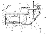
- the backlight unit 1 includes a light source 10, a parallel light generation unit 20, a light box 30, a lens array 40, a first condenser lens 51, and a second condenser lens 52. And a reflection part 60, a diffusion plate 70, a case body 80, and a lid body 90.
- the parallel light generation means 20, the light box 30, the lens array 40, the first condenser lens 51, the second condenser lens 52, the reflection unit 60, and the diffusion plate 70 are on the optical path of the light emitted from the light source 10.
- the parallel light generation means 20, the light box 30, the lens array 40, the first condenser lens 51, the reflection unit 60, the second condenser lens 52, and the diffusion plate They are arranged in the order of 70.
- the optical elements of the parallel light generating means 20, the light box 30, the lens array 40, and the first condenser lens 51 are located on the optical axis AX (see FIG. 3) of the light source 10.
- the light source 10 emits light that transmits through the liquid crystal display element 2 (hereinafter also referred to as illumination light I).
- the light source 10 includes, for example, one or a plurality of LEDs (Light (Emitting Diode).
- the light source 10 is mounted on a circuit board 11 (see FIG. 4) fixed to the case body 80.
- the circuit board 11 is formed by forming a circuit pattern on a base material made of aluminum, resin, or the like, and is conductively connected to a control unit (not shown) described later by a known method.
- the parallel light generating means 20 receives the illumination light I from the light source 10 and emits it as parallel light.
- the parallel light is light that travels substantially parallel to the optical axis AX of the light source 10 (including just parallel).
- the parallel light generating means 20 is composed of, for example, a condenser lens.
- the parallel light generation means 20 other known optical elements such as a collimator lens may be employed.
- the light box 30 receives the illumination light I that has been converted into parallel light by the parallel light generation means 20 and makes the illuminance distribution of the light on the exit side uniform.
- the light box 30 has a rectangular tube shape surrounding the optical axis AX, and the inner surface is a mirror surface.
- the light box 30 includes flange portions 30a and 30b and a positioning portion 30c (see FIG. 7B). These will be described later.
- the lens array 40 is a lens body formed by arranging a plurality of single lenses vertically and horizontally, and is a so-called fly eye lens.
- the lens array 40 is, for example, a so-called biconvex lens in which both the light source 10 side and the liquid crystal display element 2 side are convex.
- the illumination light I whose illuminance is substantially uniformed by the light box 30 is incident on the lens array 40. Since the lens array 40 generates multiple images as many as the number of lenses constituting the lens array 40, the image of one light source 10 becomes a multiple image corresponding to the number of lenses of the lens array 40. Accordingly, the liquid crystal display element 2 can be illuminated with a uniform light intensity distribution even with a small number of light sources 10.
- the lens array 40 includes a flange portion 40b (see FIG. 4) and a positioning portion 40c (see FIG. 9). These will be described later.
- the 1st condensing lens 51 and the 2nd condensing lens 52 function as a condensing means which condenses so that it may correspond to the display area A (refer FIG. 5) of the liquid crystal display element 2.
- the illumination light I from the lens array 40 is irradiated over the entire rear surface corresponding to the displayable range (display area A) of the image to be displayed. As a result, the illumination light I representing the multiple image generated by the lens array 40 can be efficiently applied to a necessary range on the back surface of the liquid crystal display element 2.
- the 1st condensing lens 51 and the 2nd condensing lens 52 consist of acrylic lenses, for example, and at least one of both is comprised as a toroidal lens. That is, at least one of the four surfaces of both the first condenser lens 51 and the second condenser lens 52 is configured as a toroidal surface.
- a liquid crystal display element that is generally often formed in a rectangular shape.
- the liquid crystal display element 2 is efficiently irradiated in accordance with the shape of the two display areas A.
- the 1st condensing lens 51 has flange part 51a, 51b and the positioning part 51c (FIG. 7 (a)). These will be described later.
- the reflector 60 is disposed between the first condenser lens 51 and the second condenser lens 52.
- the reflection part 60 is comprised from the plane mirror which vapor-deposited metals, such as aluminum, to the base material which consists of resin, glass etc., and formed the reflective surface 61, for example.
- the reflection unit 60 is disposed such that the reflection surface 61 is inclined with respect to the optical axis AX of the light source 10.
- the illumination light I from the first condenser lens 51 is reflected by the reflecting surface 61 and enters the second condenser lens 52. In this embodiment, as shown in FIG.
- the reflection unit 60 is arranged so that the optical path of the illumination light I from the reflection unit 60 to the liquid crystal display element 2 is substantially orthogonal to the optical axis AX of the light source 10. ing. In this way, the reflection unit 60 changes the optical path of the illumination light I.
- the diffusion plate 70 is made of, for example, a synthetic resin material that has at least one surface processed to be uneven, and has translucency.
- the illumination light I from the second condenser lens 52 is diffused by passing through the diffusion plate 70 and reaches the back surface of the liquid crystal display element 2.
- unevenness in illumination of the liquid crystal display element 2 is reduced as much as possible.
- the case body 80 is formed in a box shape from a resin or the like, and houses the light source 10, the parallel light generation means 20, the light box 30, the lens array 40, the first condenser lens 51, and the reflection unit 60.
- the case body 80 has an upper opening 81 (opening) and a side opening 82.
- the upper opening 81 opens toward the liquid crystal display element 2 side.
- the side opening 82 opens toward the light source 10 side.
- the upper opening 81 and the side opening 82 communicate with each other.
- the circuit board 11 is provided so as to close the side opening 82.
- the circuit board 11 is fixed to the case body 80 by fixing means (not shown) such as screws.
- the light source 10 is disposed so as to emit light toward the inside of the case body 80.
- a second condenser lens 52 is provided so as to cover an end of the upper opening 81 opposite to the light source 10. The detailed structure of the case body 80 will be described later.
- the lid 90 is formed in a plate shape from resin or the like and covers the upper opening 81 of the case body 80.
- the lid 90 is fixed to the case body 80 by fixing means such as screws 90b.
- the lid 90 has an opening 91 through which the second condenser lens 52 can be seen.
- the opening 91 has a shape corresponding to the lens surface shape of the second condenser lens 52.
- the liquid crystal display element 2 is configured, for example, by providing polarizing plates on the front and back of a TFT (Thin Film Transistor) type liquid crystal panel.
- the liquid crystal panel constituting the liquid crystal display element 2 may be a passive drive type.
- Various types of liquid crystal panels such as a TN (Twisted Nematic) type, a VA (Vertical Alignment) type, a STN (Super-Twisted Nematic) type, and a ferroelectric type are applicable.
- the liquid crystal display element 2 displays a predetermined image by switching each pixel to one of a transmissive state and a non-transmissive state under the control of a control unit (not shown).
- the control unit acquires various types of vehicle information transmitted from an ECU (Electronic Control Unit) of the vehicle C through a communication line, and causes the liquid crystal display element 2 to display an image indicating vehicle speed, fuel consumption, and the like.
- the control unit causes the light source 10 to emit light.
- the liquid crystal display element 2 is transmitted and illuminated by the illumination light I generated by the backlight unit 1, and the display light L representing the display image is emitted from the liquid crystal display element 2.
- the display light L is emitted from the display device 3 constituted by the backlight unit 1 and the liquid crystal display element 2.
- the plane mirror 4 is formed by depositing a metal such as aluminum on a base material made of resin, glass or the like to form a reflection surface.
- the plane mirror 4 reflects the display light L emitted from the display 3 toward the concave mirror 5.
- the concave mirror 5 is formed by depositing a metal such as aluminum on a substrate made of resin, glass or the like to form a reflective surface.
- the reflecting surface of the concave mirror 5 is concave, and the display light L from the display device 3 is enlarged and projected onto the windshield S. Thereby, the virtual image V visually recognized by the user U becomes the magnitude
- the housing 6 is formed in a box shape from resin or the like, and accommodates the plane mirror 4 and the concave mirror 5 therein.
- the plane mirror 4 and the concave mirror 5 are fixed inside the housing 6 by a known method.
- the housing 6 has an upper opening 6a and a lower opening 6b.
- the upper opening 6 a opens toward the windshield S and functions as an exit through which the display light L passes outside the display device 100.
- the lower opening 6b is located on the opposite side of the housing 6 from the upper opening 6a, and the liquid crystal display element 2 is disposed at the lower end thereof (the end in the downward direction in FIG. 2). In this way, the lower opening 6 b is formed so that the display surface of the liquid crystal display element 2 can be viewed toward the inside of the housing 6.
- the housing 6 is formed so as to surround the optical path of the display light L from the liquid crystal display element 2 to the upper opening 6a that functions as an emission port.
- the backlight unit 1 is attached to the housing 6 from the outside of the housing 6 and from the lower opening 6b side.
- the backlight unit 1 is attached to the casing 6 by fixing the case body 80 to the casing 6 by fixing means such as screws 8 (see FIG. 2).
- the backlight unit 1 is mounted such that the opening 91 (see FIG. 4) of the lid 90 covering the case body 80 communicates with the lower opening 6b (see FIG. 2) of the housing 6. .
- the protective member 7 is made of resin or the like, and is fixed to the casing 6 by a predetermined method so as to cover the backlight unit 1 attached to the casing 6 from the lower side (the lower side in the drawing of FIG. 2). .
- the protective member 7 provided in this way protects the backlight unit 1 from dust, vibration, and the like.
- the display light L is emitted when the display 3 displays an image.
- the display light L from the display 3 is reflected by the plane mirror 4 and the concave mirror 5 and travels toward the windshield S. In this way, the display device 100 emits the display light L toward the windshield S.
- a virtual image V of the display image is formed in front of the windshield S as viewed from the user U.
- a plurality of optical elements (the light box 30, the lens array 40, and the first condenser lens 51) arranged side by side on the optical axis AX of the light source 10 are implemented in the case body 80. Arranged in a form-specific structure. In the following, in order to facilitate understanding of this structure, as shown in FIG.
- the axis parallel to the optical axis AX of the light source 10 is the Y axis, and each optical element (light box 30, lens array 40, and first
- the XYZ coordinate system will be described in which the axis along which the condensing lens 51) stands is the Z axis (first axis), and the Y axis and the axis orthogonal to the Z axis are the X axes (second axes).
- the direction in which the arrows indicating each of the X, Y, and Z axes are directed to the + (plus) direction of each axis, and the opposite direction to the-(minus) direction of each axis will be described as appropriate.
- Each optical element located on the optical axis AX is provided with a pair of flange portions and a positioning portion.
- the first condenser lens 51 is provided with a flange portion 51a protruding in the + X direction side and a flange portion 51b protruding in the ⁇ X direction side. Yes.
- the first condenser lens 51 is provided with a positioning portion 51c that protrudes in the ⁇ Z direction.
- the first condenser lens 51 is provided with a misassembly prevention unit 51d that is located at a predetermined interval from the positioning unit 51c in the X-axis direction and protrudes in the ⁇ Z direction.
- the light box 30 is provided with a flange portion 30a protruding in the + X direction side and a flange portion 30b protruding in the ⁇ X direction side. Further, the light box 30 is provided with a positioning portion 30c protruding in the ⁇ Z direction. Similarly, the lens array 40 is also provided with a pair of flange portions (FIG. 4 shows a flange portion 40b protruding in the ⁇ X direction), and a positioning portion 40c protruding in the ⁇ Z direction. .
- the case body 80 has the upper opening 81 opened in the + Z-axis direction as described above (see FIG. 4).
- a bottom 83 is located on the opposite side of the case body 80 from the upper opening 81 in the Z-axis direction. Further, wall portions 84 and 85 that stand in the + Z-axis direction from both ends of the bottom portion 83 in the X-axis direction and face each other are formed.
- Each optical element (the light box 30, the lens array 40, and the first condenser lens 51) is located in a space surrounded by the bottom 83, the wall 84, and the wall 85.
- FIG. 6 is a view mainly showing a groove corresponding to the first condenser lens 51.
- a groove portion 841 is formed on the inner surface of the wall portion 84 located on the ⁇ X direction side (surface facing the wall portion 85). The groove 841 extends along the Z-axis direction and is recessed in the ⁇ X-axis direction. The groove portion 841 is formed so as to sandwich the flange portion 51b of the first condenser lens 51 in the Y-axis direction.
- a groove portion (not shown) that is paired with the groove portion 841 and sandwiches the flange portion 51a of the first condenser lens 51 is similarly formed. Since the flange portions 51a and 51b are sandwiched between the pair of groove portions formed in this way, the first condenser lens 51 is in a standing (standing) state along the Z-axis direction. As shown in FIG. 6, the groove portion 841 is formed so as to leave a slight gap (interval in the Y-axis direction) from the flange portion 51b.
- the flange part 51b is provided with a spring body 9 shown in FIGS.
- the spring body 9 is made of, for example, a metal spring, and includes a sandwiching portion 9a that sandwiches the flange portion 51b, a first elastic portion 9b having a restoring force in the Y-axis direction, and a first member having a restoring force in the Z-axis direction. 2 elastic portions 9c.
- the spring body 9 is attached to the 1st condensing lens 51 by inserting the flange part 51b in the clamping part 9a. In a state where the spring body 9 is attached to the flange portion 51b, the first elastic portion 9b protrudes in the ⁇ Y direction and contacts the groove portion 841 as shown in FIG.
- the first elastic portion 9b is located between the flange portion 51b and the groove portion 841, and presses the flange portion 51b against the groove portion 841 by a restoring force in the Y-axis direction.
- the second elastic portion 9c protrudes in the + Z direction as shown in FIG.
- the lid 90 that closes the upper opening 81 is attached to the case body 80.
- the second elastic portion 9c comes into contact with the surface of the lid body 90 on the ⁇ Z direction side.
- the second elastic portion 9c is located between the flange portion 51b and the lid body 90, and presses the flange portion 51 toward the bottom portion 83 by a restoring force in the Z-axis direction.
- the flange body 51a is also provided with a spring body 9.
- the first condenser lens 51 is positioned with respect to the case body 80 in the Y-axis and Z-axis directions while having vibration resistance due to the elastic force of the spring body 9.
- the spring body 9 is abbreviate
- a groove 842 sandwiching the flange 30 b is formed in the wall 84, and the wall corresponding to the flange 30 a (see FIG. 7B).
- the portion 85 is formed with a groove (not shown) that is paired with the groove 842 with the flange 30a interposed therebetween.
- the spring body 9 is also attached to each of the flange portions 30 a and 30 b of the light box 30.
- a groove 843 that sandwiches the flange 40b is formed in the wall 84, and corresponds to a flange (not shown) that is paired with the flange 40b.
- the wall 85 is formed with a groove (not shown) that is paired with the groove 843.
- the spring body 9 is attached to each of the pair of flange portions of the lens array 40. Accordingly, each optical element is positioned with respect to the case body 80 in the Y-axis and Z-axis directions while having vibration resistance due to the elastic force of the spring body 9.
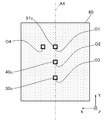
- FIG. 9 shows a rear view of the backlight unit 1 (viewed from the ⁇ Z direction).
- the bottom 83 see FIG. 4 of the case body 80
- positioning holes O1, O2, and O3 for positioning the positioning portions with respect to the case body 80 corresponding to the positioning portions 51c, 40c, and 30c of the optical elements. (Positioned part) is formed.
- the positioning holes O1, O2, and O3 pass through the bottom 83 in the Z-axis direction.
- the first condenser lens 51c is positioned with respect to the case body 80 mainly in the X-axis direction.
- each optical element is positioned in the Y-axis and Z-axis directions by the groove provided in the case body 80 and the spring body 9. In this way, each optical element is positioned with respect to the case body 80 in the XYZ directions.
- the positioning holes O 1, O 2, and O 3 are located on the optical axis AX of the light source 10. That is, the positioning portions 51c, 40c, and 30c inserted into these are also located on the optical axis AX.
- the positioning unit 51 c is provided so as to be positioned on the lens optical axis of the first condenser lens 51 when viewed from the Z-axis direction.
- the lens optical axis of the first condenser lens 51 and the light source 10 are provided. The deviation from the optical axis AX is suppressed.
- a misassembly prevention hole O4 corresponding to the misassembly prevention portion 51 d of the first condenser lens 51 is formed in the bottom 83 of the case body 80.
- the misassembly prevention hole O4 passes through the bottom 83 in the Z-axis direction.
- the misassembly prevention hole O4 is located at a predetermined distance from the positioning hole O1 in the X-axis direction. If the first condenser lens 51 is not arranged so that the misassembly prevention portion 51d is inserted into the misassembly prevention hole O4 during assembly, the first condenser lens 51 is lifted from the bottom 83 of the case body 80.
- the first condenser lens 51 is opposite to the desired direction. Thereby, it can prevent attaching the 1st condensing lens 51 accidentally.
- the light box 30 and the lens array 40 may be provided with a similar misassembly prevention unit, and the case body 80 may be provided with a misassembly prevention hole correspondingly.
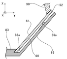
- an inclined portion 86 is formed at the end of the case body 80 on the + Y direction side.
- a resin spring portion 86 a formed integrally with the inclined portion 86 is formed on the inner surface side of the case body 80 of the inclined portion 86.
- a groove 83 a is formed at the end of the inclined portion 86 of the case body 80 on the bottom 83 side.
- the reflecting portion 60 is temporarily fixed to the case body 80 by inserting the end portion on the ⁇ Z direction side into the groove portion 83a.
- An inclined surface 92 is formed on the ⁇ Z direction side of the end of the lid 90 on the + Y direction side.
- the inclined surface 92 abuts against the end portion on the + Z direction side of the reflecting portion 60 and presses the reflecting portion 60 toward the inclined portion 86 of the case body 80.
- the resin spring portion 86a formed in the inclined portion 86 is formed with a restoring force in the normal direction of the reflecting surface 61 of the reflecting portion 60, and when the reflecting portion 60 is pressed by the lid 90, The opposite side, that is, the reflecting portion 60 is pressed toward the lid 90. Since the end portion on the ⁇ Z direction side of the reflecting portion 60 is supported by the groove portion 83a, the reflecting portion 60 acts in the opposite directions with the end portion on the ⁇ Z direction side serving as a fulcrum.
- the case body 80 Since the force from the balance and the force from the resin spring portion 86a balance, the case body 80 is disposed.
- the inclined surface 92 of the lid 90 and the inclined portion 86 and groove 83a of the case body 80 are set so that the reflecting surface 61 of the reflecting portion 60 has a desired inclination. In this way, the reflecting portion 60 is disposed in the case body 80 while having vibration resistance due to the elastic force of the resin spring portion 86a.
- the reason why the elastic member for imparting vibration resistance to each of the optical elements described above is a metal spring instead of a resin spring.
- the spring body 9 can be formed of a resin spring, and the elastic member that comes into contact with the reflecting portion 60 is formed of a metal spring separate from the case body 80. You can also.
- the display device 100 described above emits display light L representing an image displayed by the liquid crystal display element 2 toward a transparent member (for example, the windshield S), and a virtual image of the image by the display light L reflected by the transparent member.
- a display device 100 that displays V a light source 10 that emits light that illuminates the liquid crystal display element 2 from the side opposite to the image display side, and a light source 10 between the light source 10 and the liquid crystal display element 2.
- Optical elements first condensing lens 51, lens array 40, light box 30 disposed on the optical axis AX, and a case body 80 for housing the optical elements.
- the upper opening 81 that opens in the direction, the bottom 83 that is located on the opposite side of the upper opening 81 in the Z-axis direction, and the upper opening 81 and the bottom 83 are positioned along the Z-axis direction.
- the optical element has protrusions (flange portions 51a, 51b, 30a, 30b, etc.) protruding in the X-axis direction, and the protrusions are sandwiched between the groove portions.
- the case body 80 is housed in a state of standing along the Z-axis direction.
- the optical element Since it did in this way, since it can be confirmed whether the optical element is arrange
- the display device 100 includes a lid 90 that closes the upper opening 81, a first elastic portion 9 b that is positioned between the protrusion and the groove, and presses the protrusion against the groove, and the protrusion and the lid 90. And a second elastic portion 9c that presses the protruding portion toward the bottom 83. In this way, vibration resistance can be imparted to the optical element by the elastic force of the first elastic part 9b and the second elastic part 9c, while the optical element can be easily assembled.
- a positioning part (positioning part 51c and the like) is provided on the bottom part 83 side of the optical element, and a positioned part (positioning hole O1 and the like) for positioning the positioning part is provided on the bottom part 83 from the Z-axis direction.
- the positioning portion and the positioned portion are located on the optical axis AX. Since it did in this way, it is possible to suppress the shift
- the display device 100 further includes a reflection unit 60 that is located between the optical element and the liquid crystal display element 2 and has a reflection surface 61 that reflects the light emitted from the light source 10 toward the liquid crystal display element 2. Since the 61 is inclined with respect to the optical axis AX, the light path from the light source AX to the liquid crystal display element 2 is configured to be bent by the reflecting portion 61.
- the reflecting surface 61 of the reflecting portion 60 may be formed in a curved surface shape, for example, a spherical surface, a toroidal surface, a conic surface, or a free curved surface.
- the reflecting unit 60 can exhibit a lens effect and have a function of controlling the light distribution to the liquid crystal display element 2, for example, when the condensing means is configured by one condensing lens Even so, the light distribution can be accurately controlled.
- the condensing means is composed of two or more condensing lenses, it is possible to reduce the number of condensing lenses by the same effect, so that space saving and cost reduction can be achieved.
- the display image L is reflected by the windshield S of the vehicle C so that the user U can visually recognize the display image.
- the display device 100 may include a dedicated combiner (an example of a transparent member), and the display image may be visually recognized by reflecting the display light L with the combiner.
- an example of a vehicle on which the display device 100 is mounted is the vehicle C, but is not limited thereto.
- the display device 100 may be mounted on another vehicle such as a motorcycle, a construction machine, an agricultural machine, a ship, an aircraft, or the like.
- the present invention relates to a display device such as a head-up display device that emits display light representing an image displayed by a liquid crystal display element toward a windshield (transparent member) and displays a virtual image of the image by display light reflected by the windshield. It is possible to apply to.
- a display device such as a head-up display device that emits display light representing an image displayed by a liquid crystal display element toward a windshield (transparent member) and displays a virtual image of the image by display light reflected by the windshield. It is possible to apply to.
- DESCRIPTION OF SYMBOLS 100 ... Display apparatus 1 ... Backlight unit 10 ... Light source 20 ... Parallel light production
- generation means 30 ... Light box 30a, 30b ... Flange part 30c ... Positioning part 40 ... Lens array 40b ... Flange part 40c ... Positioning part 51 ... 1st collection Optical lens (Condenser lens) 51a, 51b ... Flange part 51c ... Positioning part 51d ... Misassembly prevention part 52 ... Second condenser lens 60 ... Reflection part 70 ... Diffuser 80 ... Case body 81 ... Upper opening part (opening part) 83 ... Bottom O1, O2, O3 ... Positioning hole (positioned part) O4 ...
Landscapes
- Physics & Mathematics (AREA)
- Nonlinear Science (AREA)
- Chemical & Material Sciences (AREA)
- General Physics & Mathematics (AREA)
- Optics & Photonics (AREA)
- Engineering & Computer Science (AREA)
- Crystallography & Structural Chemistry (AREA)
- Mathematical Physics (AREA)
- Mechanical Engineering (AREA)
- Transportation (AREA)
- Combustion & Propulsion (AREA)
- Instrument Panels (AREA)
- Liquid Crystal (AREA)
Abstract
Description
液晶表示素子が表示する像を表す表示光を透明部材に向けて出射し、前記透明部材で反射した表示光により前記像の虚像を表示する表示装置であって、
前記液晶表示素子を前記像の表示側とは反対側から照明する光を出射する光源と、
前記光源と前記液晶表示素子との間であって前記光源の光軸上に配置された光学素子と、
前記光学素子を収納するケース体と、を備え、
前記ケース体は、前記光軸と略直交する第1の軸方向に向かって開口する開口部と、前記第1の軸方向において前記開口部とは反対側に位置する底部と、前記開口部と前記底部との間に位置し、前記第1の軸方向に沿って延び、且つ、前記光軸及び前記第1の軸と直交する第2の軸方向に窪む溝部と、を有し、
前記光学素子は、前記第2の軸方向に突出する突出部を有し、前記突出部が前記溝部に挟まっていることで、前記第1の軸方向に沿って立った状態で前記ケース体に収納されている、
ことを特徴とする。
バックライトユニット1は、図3に示すように、光源10と、平行光生成手段20と、ライトボックス30と、レンズアレイ40と、第1の集光レンズ51と、第2の集光レンズ52と、反射部60と、拡散板70と、ケース体80と、蓋体90と、を備える。
また、ライトボックス30は、フランジ部30a,30bと位置決め部30cとを有する(図7(b)参照)。これらについては後述する。
また、レンズアレイ40は、フランジ部40b(図4参照)と位置決め部40c(図9参照)とを有する。これらについては後述する。
また、第1の集光レンズ51は、フランジ部51a,51bと位置決め部51cとを有する(図7(a))。これらについては後述する。
液晶表示素子2は、例えば、TFT(Thin Film Transistor)型の液晶パネルの前面及び背面に偏光板を設けることで構成されている。なお、液晶表示素子2を構成する液晶パネルは、パッシブ駆動型のものであってもよい。また、液晶パネルとして、TN(Twisted Nematic)型、VA(Vertical Alignment)型、STN(Super-Twisted Nematic)型、強誘電性型等の様々な型のものが適用可能である。
このようにして、バックライトユニット1と液晶表示素子2とから構成される表示器3から表示光Lが出射される。
図2に戻って、平面鏡4は、樹脂、ガラス等からなる基材にアルミニウム等の金属を蒸着させ反射面を形成して成る。平面鏡4は、表示器3が発した表示光Lを凹面鏡5に向け反射させる。
図2に示すように、バックライトユニット1は、筐体6の外側であって下部開口部6b側から、筐体6に取り付けられている。例えば、ビス8(図2参照)等の固定手段でケース体80が筐体6に固定されることにより、バックライトユニット1は、筐体6に取り付けられている。この際、ケース体80を覆う蓋体90の開口部91(図4参照)が、筐体6の下部開口部6b(図2参照)と通じるようにして、バックライトユニット1は取り付けられている。
(1)表示器3が画像を表示することで表示光Lが出射される。表示器3からの表示光Lは平面鏡4及び凹面鏡5で反射し、ウインドシールドSに向かう。このようにして、表示装置100は表示光LをウインドシールドSに向けて出射する。
(2)表示装置100からの表示光LがウインドシールドSで反射することで、ユーザUから見てウインドシールドSの前方に表示画像の虚像Vが結ばれる。
以下では、この構造の理解を容易にするため、図4等に示すように、光源10の光軸AXと平行な軸をY軸、各光学素子(ライトボックス30、レンズアレイ40、及び第1の集光レンズ51)が立つ方向に沿う軸をZ軸(第1の軸)、Y軸及びZ軸と直交する軸をX軸(第2の軸)としたXYZ座標系を用いて説明する。なお、図面においてX、Y、Z軸の各々を示す矢印が向く方向を各軸の+(プラス)方向とし、その反対方向を各軸の-(マイナス)方向として、適宜、説明する。
光軸AX上に位置する各光学素子には、一対のフランジ部と、位置決め部とが設けられている。
具体的には、図7(a)に示すように、第1の集光レンズ51には、+X方向側に突出するフランジ部51aと-X方向側に突出するフランジ部51bとが設けられている。また、第1の集光レンズ51には、-Z方向に突出する位置決め部51cが設けられている。また、第1の集光レンズ51には、位置決め部51cからX軸方向に所定の間隔を空けて位置し、-Z方向に突出する誤組み防止部51dが設けられている。
図7(b)に示すように、ライトボックス30には、+X方向側に突出するフランジ部30aと-X方向側に突出するフランジ部30bとが設けられている。また、ライトボックス30には、-Z方向に突出する位置決め部30cが設けられている。
レンズアレイ40にも同様に一対のフランジ部が設けられており(図4に-X方向に突出するフランジ部40bを示した)、また、-Z方向に突出する位置決め部40cが設けられている。
-X方向側に位置する壁部84の内面(壁部85と対向する面)には、溝部841が形成されている。溝部841は、Z軸方向に沿って延び、且つ、-X軸方向に窪んでいる。溝部841は、第1の集光レンズ51のフランジ部51bをY軸方向において挟むように形成されている。壁部85の内面には、溝部841と対となり、第1の集光レンズ51のフランジ部51aを挟む溝部(図示せず)が同様に形成されている。このように形成された一対の溝部にフランジ部51a,51bが挟まっていることで、第1の集光レンズ51は、Z軸方向に沿って立った(起立した)状態となっている。溝部841は、図6に示すように、フランジ部51bと若干の隙間(Y軸方向の間隔)を空けるように形成されている。
ばね体9は、挟込部9aにフランジ部51bを差し込むことにより、第1の集光レンズ51に取り付けられる。ばね体9がフランジ部51bに取り付けられた状態では、第1の弾性部9bは、図6に示すように、-Y方向に突出しており、溝部841と当接する。第1の弾性部9bは、フランジ部51bと溝部841との間に位置し、Y軸方向における復元力により、フランジ部51bを溝部841に押し付ける。また、ばね体9がフランジ部51bに取り付けられた状態では、第2の弾性部9cは、図6に示すように、+Z方向に突出している。ここで、前述したように、ケース体80には、上部開口部81を塞ぐ蓋体90が取り付けられる。蓋体90がケース体80に取り付けられると、第2の弾性部9cは、蓋体90の-Z方向側の面と当接する。これにより、第2の弾性部9cは、フランジ部51bと蓋体90との間に位置し、Z軸方向における復元力により、フランジ部51を底部83に向けて押し付ける。同様に、図7(a)に示すように、フランジ部51aにも、ばね体9が設けられている。
これにより、第1の集光レンズ51は、ばね体9の弾性力により耐振動性を有しつつ、Y軸及びZ軸方向において、ケース体80に対して位置決めされる。なお、既述の図3及び図4では、見易さを考慮してばね体9を省略している。
同様に、レンズアレイ40に対応して、図4に示すように、壁部84にはフランジ部40bを挟む溝部843が形成され、フランジ部40bと対となるフランジ部(図示せず)に対応して壁部85には溝部843と対となる溝部(図示せず)が形成されている。そして、図示しないが、レンズアレイ40の一対のフランジ部の各々にも、ばね体9が取り付けられている。
これにより、各光学素子は、ばね体9の弾性力により耐振動性を有しつつ、Y軸及びZ軸方向において、ケース体80に対して位置決めされている。
ケース体80の底部83(図4参照)には、各光学素子の位置決め部51c,40c,30cに対応して、各位置決め部がケース体80に対して位置決めされる位置決め孔O1,O2,O3(被位置決め部)が形成されている。位置決め孔O1,O2,O3は、底部83をZ軸方向に貫通している。位置決め部51cが位置決め孔O1に挿入され、両者が嵌め合わされることにより、第1の集光レンズ51cは、主にX軸方向においてケース体80に対して位置決めされる。位置決め部40cが位置決め孔O2に挿入され、両者が嵌め合わされることにより、レンズアレイ40は、主にX軸方向においてケース体80に対して位置決めされる。位置決め部30cが位置決め孔O3に挿入され、両者が嵌め合わされることにより、ライトボックス30は、主にX軸方向においてケース体80に対して位置決めされる。また、前述のように、各光学素子は、ケース体80に設けられた溝部とばね体9とでY軸及びZ軸方向において位置決めされている。このようにして、各光学素子は、ケース体80に対してXYZ方向において位置決めされる。
図10に示すように、ケース体80の+Y方向側の端部には、傾斜部86が形成されている。傾斜部86のケース体80の内面側には、傾斜部86と一体に形成された樹脂ばね部86aが形成されている。また、ケース体80の傾斜部86の底部83側の端部には溝部83aが形成されている。反射部60は、-Z方向側の端部が溝部83aに挿入されることにより、ケース体80に対して仮止めされる。蓋体90の+Y方向側の端部の-Z方向側には、傾斜面92が形成されている。この傾斜面92は、蓋体90がケース体80に取り付けられると、反射部60の+Z方向側の端部と当接し、反射部60をケース体80の傾斜部86に向けて押しつける。一方、傾斜部86に形成された樹脂ばね部86aは、反射部60の反射面61の法線方向に復元力を有して形成されており、反射部60が蓋体90によって押し付けられると、その逆側、つまり、反射部60を蓋体90に向けて押しつける。反射部60の-Z方向側の端部は溝部83aに支持されているため、反射部60は、-Z方向側の端部を支点として、互いに逆方向に働く、蓋体90の傾斜面92からの力と樹脂ばね部86aからの力とがつり合うことで、ケース体80に対して配設される。なお、蓋体90の傾斜面92と、ケース体80の傾斜部86及び溝部83aとは、反射部60の反射面61が所望の傾きとなるように設定されている。
このようにして、反射部60は、樹脂ばね部86aの弾性力により、耐振動性を有しつつ、ケース体80に配設されている。なお、この実施形態で、前述した各光学素子(第1の集光レンズ51、レンズアレイ40、ライトボックス30)に耐振動性を付与する弾性部材を樹脂ばねでなく金属ばねとした理由は、各光学素子が比較的、光源10に近いことから、光源10近傍の温度上昇によっても部材の変形等が生じないようにするためである。したがって、耐振動性を満足させる観点からは、ばね体9を樹脂ばねで形成することもできるし、反射部60に当接する弾性部材を、ケース体80とは別体の金属ばねで形成することもできる。
また、表示装置100は、光学素子と液晶表示素子2の間に位置し、光源10が出射した光を液晶表示素子2に向けて反射させる反射面61を有する反射部60をさらに備え、反射面61が光軸AXに対して傾斜していることで、光源AXから液晶表示素子2に至る光の光路が反射部61で折り曲がるように構成されている。
以上では、第1の弾性部9bと第2の弾性部9cとが、ばね体9と一体に形成される例を示したが、これに限られない。第1の弾性部9b及び第2の弾性部9cの各々と同様の機能を有する弾性部材を別体に構成してもよい。また、以上では、第1の弾性部9bが-Y方向に突出している例を示したが、+Y方向に突出していてもよい。
1…バックライトユニット
10…光源
20…平行光生成手段
30…ライトボックス
30a,30b…フランジ部
30c…位置決め部
40…レンズアレイ
40b…フランジ部
40c…位置決め部
51…第1の集光レンズ(集光レンズ)
51a,51b…フランジ部
51c…位置決め部
51d…誤組み防止部
52…第2の集光レンズ
60…反射部
70…拡散板
80…ケース体
81…上部開口部(開口部)
83…底部
O1,O2,O3…位置決め孔(被位置決め部)
O4…誤組み防止孔
84,85…壁部
841,842,843…溝部
90…蓋体
2…液晶表示素子
3…表示器
9…ばね体
9a…挟込部
9b…第1の弾性部
9c…第2の弾性部
AX…光軸
I…照明光
L…表示光
V…虚像
U…ユーザ
Claims (5)
- 液晶表示素子が表示する像を表す表示光を透明部材に向けて出射し、前記透明部材で反射した表示光により前記像の虚像を表示する表示装置であって、
前記液晶表示素子を前記像の表示側とは反対側から照明する光を出射する光源と、
前記光源と前記液晶表示素子との間であって前記光源の光軸上に配置された光学素子と、
前記光学素子を収納するケース体と、を備え、
前記ケース体は、前記光軸と略直交する第1の軸方向に向かって開口する開口部と、前記第1の軸方向において前記開口部とは反対側に位置する底部と、前記開口部と前記底部との間に位置し、前記第1の軸方向に沿って延び、且つ、前記光軸及び前記第1の軸と直交する第2の軸方向に窪む溝部と、を有し、
前記光学素子は、前記第2の軸方向に突出する突出部を有し、前記突出部が前記溝部に挟まっていることで、前記第1の軸方向に沿って立った状態で前記ケース体に収納されている、
ことを特徴とする表示装置。 - 前記開口部を塞ぐ蓋体と、
前記突出部と前記溝部との間に位置し、前記突出部を前記溝部に押し付ける第1の弾性部と、
前記突出部と前記蓋体との間に位置し、前記突出部を前記底部に向けて押し付ける第2の弾性部と、をさらに備える、
ことを特徴とする請求項1に記載の表示装置。 - 前記光学素子の前記底部側には位置決め部が設けられ、
前記底部には、前記位置決め部が位置決めされる被位置決め部が設けられ、
前記第1の軸方向から見て、前記位置決め部と前記被位置決め部は、前記光軸上に位置する、
ことを特徴とする請求項1又は2に記載の表示装置。 - 前記光学素子は、前記光軸が向く方向に間隔を空けて複数あり、それらの少なくとも1つは前記光源が出射した光を前記液晶表示素子の表示領域に対応するように集光する集光レンズであり、
前記溝部も前記光学素子の各々に対応して複数設けられている、
ことを特徴とする請求項1乃至3のいずれか1項に記載の表示装置。 - 前記光学素子と前記液晶表示素子の間に位置し、前記光源が出射した光を前記液晶表示素子に向けて反射させる反射面を有する反射部をさらに備え、
前記反射面が前記光軸に対して傾斜していることで、前記光源から前記液晶表示素子に至る光の光路が前記反射部で折り曲がるように構成されている、
ことを特徴とする請求項1乃至4のいずれか1項に記載の表示装置。
Priority Applications (4)
| Application Number | Priority Date | Filing Date | Title |
|---|---|---|---|
| US15/027,222 US10029570B2 (en) | 2013-10-24 | 2014-10-16 | Display apparatus |
| KR1020167011799A KR20160078983A (ko) | 2013-10-24 | 2014-10-16 | 표시장치 |
| CN201480058188.3A CN105659145B (zh) | 2013-10-24 | 2014-10-16 | 显示装置 |
| EP14856777.9A EP3062141B1 (en) | 2013-10-24 | 2014-10-16 | Display apparatus |
Applications Claiming Priority (2)
| Application Number | Priority Date | Filing Date | Title |
|---|---|---|---|
| JP2013221546A JP6263953B2 (ja) | 2013-10-24 | 2013-10-24 | 表示装置 |
| JP2013-221546 | 2013-10-24 |
Publications (1)
| Publication Number | Publication Date |
|---|---|
| WO2015060194A1 true WO2015060194A1 (ja) | 2015-04-30 |
Family
ID=52992793
Family Applications (1)
| Application Number | Title | Priority Date | Filing Date |
|---|---|---|---|
| PCT/JP2014/077561 Ceased WO2015060194A1 (ja) | 2013-10-24 | 2014-10-16 | 表示装置 |
Country Status (6)
| Country | Link |
|---|---|
| US (1) | US10029570B2 (ja) |
| EP (1) | EP3062141B1 (ja) |
| JP (1) | JP6263953B2 (ja) |
| KR (1) | KR20160078983A (ja) |
| CN (1) | CN105659145B (ja) |
| WO (1) | WO2015060194A1 (ja) |
Cited By (2)
| Publication number | Priority date | Publication date | Assignee | Title |
|---|---|---|---|---|
| WO2017038498A1 (ja) * | 2015-08-31 | 2017-03-09 | 日本精機株式会社 | ミラー装置及びヘッドアップディスプレイ装置 |
| CN107065176A (zh) * | 2015-10-21 | 2017-08-18 | 矢崎总业株式会社 | 平视显示器装置 |
Families Citing this family (18)
| Publication number | Priority date | Publication date | Assignee | Title |
|---|---|---|---|---|
| JP6702770B2 (ja) * | 2015-08-28 | 2020-06-03 | 日本電産コパル株式会社 | 撮像ユニット並びにこれを備える車両用のフロントガラス及び車両 |
| CN206387958U (zh) * | 2015-12-14 | 2017-08-08 | 矽创电子股份有限公司 | 光学成像装置 |
| JP6882904B2 (ja) * | 2017-01-30 | 2021-06-02 | 株式会社デンソーテン | 画像記憶装置 |
| JP7053201B2 (ja) * | 2017-09-15 | 2022-04-12 | 日本電産サンキョー株式会社 | 駆動装置 |
| JP7072360B2 (ja) * | 2017-09-15 | 2022-05-20 | 日本電産サンキョー株式会社 | 駆動装置 |
| JP7126075B2 (ja) * | 2017-09-15 | 2022-08-26 | 日本精機株式会社 | ヘッドアップディスプレイ装置 |
| WO2019116730A1 (ja) * | 2017-12-11 | 2019-06-20 | パナソニックIpマネジメント株式会社 | ヘッドアップディスプレイおよびヘッドアップディスプレイを搭載した移動体 |
| EP3726276B1 (en) | 2017-12-11 | 2023-03-22 | Panasonic Intellectual Property Management Co., Ltd. | Head-up display and moving body with head-up display mounted thereon |
| CN110796946A (zh) * | 2018-08-03 | 2020-02-14 | 深圳前海智云谷科技有限公司 | 成像单元及其汽车抬头显示系统 |
| DE112020000507T5 (de) * | 2019-01-25 | 2021-11-18 | Nippon Seiki Co., Ltd. | Head-Up-Display-Vorrichtung |
| EP3992692B1 (en) * | 2019-06-26 | 2023-08-23 | JVCKenwood Corporation | Head-up display device |
| JP7552610B2 (ja) | 2019-10-31 | 2024-09-18 | 日本精機株式会社 | ヘッドアップディスプレイ装置 |
| JP7759552B2 (ja) * | 2022-03-30 | 2025-10-24 | 日本精機株式会社 | 表示装置 |
| CN114815264B (zh) * | 2022-05-26 | 2023-11-07 | 业成科技(成都)有限公司 | 图像生成单元、其装配方法、抬头显示系统及交通工具 |
| JP2024163736A (ja) * | 2023-05-12 | 2024-11-22 | 矢崎総業株式会社 | 車両用表示装置 |
| CN116953931A (zh) * | 2023-06-07 | 2023-10-27 | 深圳市锐思华创技术有限公司 | 一种用于轨道交通的抬头显示设备及其光路装置 |
| CN116841047A (zh) * | 2023-06-07 | 2023-10-03 | 深圳市锐思华创技术有限公司 | 一种用于轨道交通的抬头显示设备及其光路装置 |
| KR102786731B1 (ko) | 2024-07-17 | 2025-03-25 | 최해용 | 입체 컬렉션 카드시스템 |
Citations (5)
| Publication number | Priority date | Publication date | Assignee | Title |
|---|---|---|---|---|
| JPH08136880A (ja) * | 1994-11-02 | 1996-05-31 | Nippondenso Co Ltd | ヘッドアップディスプレイ型液晶表示装置 |
| JPH09146090A (ja) * | 1995-11-16 | 1997-06-06 | Yazaki Corp | ヘッドアップディスプレイ用光源ユニット |
| JPH09159986A (ja) * | 1995-12-13 | 1997-06-20 | Kansei Corp | 車両用情報表示装置 |
| JP2010276776A (ja) * | 2009-05-27 | 2010-12-09 | Nippon Seiki Co Ltd | ヘッドアップディスプレイ装置 |
| JP2011191723A (ja) | 2010-02-22 | 2011-09-29 | Nippon Seiki Co Ltd | 照明装置 |
Family Cites Families (5)
| Publication number | Priority date | Publication date | Assignee | Title |
|---|---|---|---|---|
| JP3720464B2 (ja) * | 1995-07-03 | 2005-11-30 | キヤノン株式会社 | 光学素子及びそれを用いた観察系 |
| CN2727793Y (zh) * | 2004-08-11 | 2005-09-21 | 鸿富锦精密工业(深圳)有限公司 | 背光模组和液晶显示装置 |
| US7978414B2 (en) * | 2007-09-28 | 2011-07-12 | Jabil Circuit, Inc. | Positioning system for a combiner in a head up display |
| CN101392895B (zh) * | 2008-10-08 | 2010-06-02 | 友达光电(苏州)有限公司 | 背光模组 |
| CN101699155B (zh) * | 2009-10-23 | 2011-05-18 | 苏州中兴联精密工业有限公司 | 电连接器 |
-
2013
- 2013-10-24 JP JP2013221546A patent/JP6263953B2/ja active Active
-
2014
- 2014-10-16 US US15/027,222 patent/US10029570B2/en active Active
- 2014-10-16 KR KR1020167011799A patent/KR20160078983A/ko not_active Ceased
- 2014-10-16 EP EP14856777.9A patent/EP3062141B1/en active Active
- 2014-10-16 WO PCT/JP2014/077561 patent/WO2015060194A1/ja not_active Ceased
- 2014-10-16 CN CN201480058188.3A patent/CN105659145B/zh active Active
Patent Citations (5)
| Publication number | Priority date | Publication date | Assignee | Title |
|---|---|---|---|---|
| JPH08136880A (ja) * | 1994-11-02 | 1996-05-31 | Nippondenso Co Ltd | ヘッドアップディスプレイ型液晶表示装置 |
| JPH09146090A (ja) * | 1995-11-16 | 1997-06-06 | Yazaki Corp | ヘッドアップディスプレイ用光源ユニット |
| JPH09159986A (ja) * | 1995-12-13 | 1997-06-20 | Kansei Corp | 車両用情報表示装置 |
| JP2010276776A (ja) * | 2009-05-27 | 2010-12-09 | Nippon Seiki Co Ltd | ヘッドアップディスプレイ装置 |
| JP2011191723A (ja) | 2010-02-22 | 2011-09-29 | Nippon Seiki Co Ltd | 照明装置 |
Cited By (3)
| Publication number | Priority date | Publication date | Assignee | Title |
|---|---|---|---|---|
| WO2017038498A1 (ja) * | 2015-08-31 | 2017-03-09 | 日本精機株式会社 | ミラー装置及びヘッドアップディスプレイ装置 |
| JPWO2017038498A1 (ja) * | 2015-08-31 | 2018-06-21 | 日本精機株式会社 | ミラー装置及びヘッドアップディスプレイ装置 |
| CN107065176A (zh) * | 2015-10-21 | 2017-08-18 | 矢崎总业株式会社 | 平视显示器装置 |
Also Published As
| Publication number | Publication date |
|---|---|
| EP3062141A1 (en) | 2016-08-31 |
| EP3062141A4 (en) | 2017-03-22 |
| KR20160078983A (ko) | 2016-07-05 |
| US10029570B2 (en) | 2018-07-24 |
| JP6263953B2 (ja) | 2018-01-24 |
| US20160243942A1 (en) | 2016-08-25 |
| CN105659145B (zh) | 2018-10-23 |
| JP2015082104A (ja) | 2015-04-27 |
| EP3062141B1 (en) | 2019-04-03 |
| CN105659145A (zh) | 2016-06-08 |
Similar Documents
| Publication | Publication Date | Title |
|---|---|---|
| JP6263953B2 (ja) | 表示装置 | |
| JP6248473B2 (ja) | ヘッドアップディスプレイ装置 | |
| WO2016047621A1 (ja) | ヘッドアップディスプレイ装置 | |
| US11169375B2 (en) | Lighting unit and head-up display device | |
| JP6365174B2 (ja) | ヘッドアップディスプレイ装置 | |
| KR20130020595A (ko) | 액정 표시 장치 및 전자 기기 | |
| JP2016065907A (ja) | ヘッドアップディスプレイ装置 | |
| CN115202049B (zh) | 车辆用显示装置 | |
| JP5790439B2 (ja) | 照明装置、表示装置および電子機器 | |
| JP7704146B2 (ja) | ヘッドアップディスプレイ装置 | |
| JP2018180291A (ja) | 車両用表示装置 | |
| JP2010276776A (ja) | ヘッドアップディスプレイ装置 | |
| JP2007219489A (ja) | 液晶表示装置およびそれを用いたヘッドアップディスプレイ | |
| JP5526974B2 (ja) | 照明装置 | |
| JP2009109798A (ja) | ヘッドアップディスプレイ装置 | |
| JP2008185753A (ja) | 表示装置 | |
| CN223377553U (zh) | 显示装置及平视显示装置 | |
| KR101688991B1 (ko) | 반사시트 및 이를 구비하는 백라이트 장치 | |
| JP2013068763A (ja) | 反射型液晶表示装置 | |
| JP2025009823A (ja) | ヘッドアップディスプレイ装置 | |
| JP2020068162A (ja) | バックライトユニットおよびヘッドアップディスプレイ装置 | |
| KR20160092570A (ko) | 플레이트 버텀 및 이를 갖는 액정표시장치 | |
| JP2022063480A (ja) | 表示装置 | |
| JP2017102305A (ja) | ヘッドアップディスプレイ装置 |
Legal Events
| Date | Code | Title | Description |
|---|---|---|---|
| 121 | Ep: the epo has been informed by wipo that ep was designated in this application |
Ref document number: 14856777 Country of ref document: EP Kind code of ref document: A1 |
|
| WWE | Wipo information: entry into national phase |
Ref document number: 15027222 Country of ref document: US |
|
| NENP | Non-entry into the national phase |
Ref country code: DE |
|
| ENP | Entry into the national phase |
Ref document number: 20167011799 Country of ref document: KR Kind code of ref document: A |
|
| REEP | Request for entry into the european phase |
Ref document number: 2014856777 Country of ref document: EP |
|
| WWE | Wipo information: entry into national phase |
Ref document number: 2014856777 Country of ref document: EP |