WO2015060291A1 - 無線機器、無線通信システム、無線モジュール、インターフェイスモジュール、及び通信方法 - Google Patents
無線機器、無線通信システム、無線モジュール、インターフェイスモジュール、及び通信方法 Download PDFInfo
- Publication number
- WO2015060291A1 WO2015060291A1 PCT/JP2014/077920 JP2014077920W WO2015060291A1 WO 2015060291 A1 WO2015060291 A1 WO 2015060291A1 JP 2014077920 W JP2014077920 W JP 2014077920W WO 2015060291 A1 WO2015060291 A1 WO 2015060291A1
- Authority
- WO
- WIPO (PCT)
- Prior art keywords
- message
- wireless
- module
- interface module
- data
- Prior art date
- Legal status (The legal status is an assumption and is not a legal conclusion. Google has not performed a legal analysis and makes no representation as to the accuracy of the status listed.)
- Ceased
Links
Images


Classifications
-
- H—ELECTRICITY
- H04—ELECTRIC COMMUNICATION TECHNIQUE
- H04W—WIRELESS COMMUNICATION NETWORKS
- H04W4/00—Services specially adapted for wireless communication networks; Facilities therefor
- H04W4/70—Services for machine-to-machine communication [M2M] or machine type communication [MTC]
-
- G—PHYSICS
- G05—CONTROLLING; REGULATING
- G05B—CONTROL OR REGULATING SYSTEMS IN GENERAL; FUNCTIONAL ELEMENTS OF SUCH SYSTEMS; MONITORING OR TESTING ARRANGEMENTS FOR SUCH SYSTEMS OR ELEMENTS
- G05B19/00—Program-control systems
- G05B19/02—Program-control systems electric
- G05B19/04—Program control other than numerical control, i.e. in sequence controllers or logic controllers
- G05B19/042—Program control other than numerical control, i.e. in sequence controllers or logic controllers using digital processors
-
- H—ELECTRICITY
- H04—ELECTRIC COMMUNICATION TECHNIQUE
- H04B—TRANSMISSION
- H04B1/00—Details of transmission systems, not covered by a single one of groups H04B3/00 - H04B13/00; Details of transmission systems not characterised by the medium used for transmission
- H04B1/38—Transceivers, i.e. devices in which transmitter and receiver form a structural unit and in which at least one part is used for functions of transmitting and receiving
-
- H—ELECTRICITY
- H04—ELECTRIC COMMUNICATION TECHNIQUE
- H04L—TRANSMISSION OF DIGITAL INFORMATION, e.g. TELEGRAPHIC COMMUNICATION
- H04L67/00—Network arrangements or protocols for supporting network services or applications
- H04L67/01—Protocols
- H04L67/12—Protocols specially adapted for proprietary or special-purpose networking environments, e.g. medical networks, sensor networks, networks in vehicles or remote metering networks
-
- G—PHYSICS
- G05—CONTROLLING; REGULATING
- G05B—CONTROL OR REGULATING SYSTEMS IN GENERAL; FUNCTIONAL ELEMENTS OF SUCH SYSTEMS; MONITORING OR TESTING ARRANGEMENTS FOR SUCH SYSTEMS OR ELEMENTS
- G05B2219/00—Program-control systems
- G05B2219/20—Pc systems
- G05B2219/25—Pc structure of the system
- G05B2219/25187—Transmission of signals, medium, ultrasonic, radio
-
- G—PHYSICS
- G05—CONTROLLING; REGULATING
- G05B—CONTROL OR REGULATING SYSTEMS IN GENERAL; FUNCTIONAL ELEMENTS OF SUCH SYSTEMS; MONITORING OR TESTING ARRANGEMENTS FOR SUCH SYSTEMS OR ELEMENTS
- G05B2219/00—Program-control systems
- G05B2219/20—Pc systems
- G05B2219/25—Pc structure of the system
- G05B2219/25428—Field device
-
- H—ELECTRICITY
- H04—ELECTRIC COMMUNICATION TECHNIQUE
- H04W—WIRELESS COMMUNICATION NETWORKS
- H04W4/00—Services specially adapted for wireless communication networks; Facilities therefor
- H04W4/80—Services using short range communication, e.g. near-field communication [NFC], radio-frequency identification [RFID] or low energy communication
Definitions
- the present invention relates to a wireless device, a wireless communication system, a wireless module, an interface module, and a communication method.
- field devices measuring instruments, operating devices
- control devices for controlling these devices
- DCS distributed control system
- Field devices that constitute such a distributed control system perform wired communication.
- field wireless devices that perform wireless communication conforming to industrial wireless communication standards such as ISA100.11a and WirelessHART (registered trademark) have been realized.
- the wireless field device generally includes an input / output unit that measures or manipulates state quantities (for example, pressure, temperature, flow rate, etc.) in an industrial process, and wireless communication that performs wireless communication in accordance with the industrial wireless communication standard. And a control unit that controls the operation of the field wireless device in an integrated manner.
- each part in the field wireless device operates by power supplied from a single power source.
- the wireless field device does not need to be connected to a communication line or a communication bus unlike a conventional field device, and is basically installed alone in a plant or the like. For this reason, the wireless field device incorporates a battery as the single power source.
- Patent Document 1 discloses a wireless device that is attached to a conventional field device that does not have a wireless communication unit and can operate the conventional field device as the above-described wireless field device.
- a wireless device disclosed in Patent Document 1 below includes an interface unit connected to a conventional field device, a wireless communication unit that performs wireless communication, and power to the conventional field device via the interface unit. And a power supply unit to supply.
- the wireless device transmits the signal from the wireless communication unit to a transmission destination (for example, a host controller).
- the wireless device receives a signal addressed to the field device by the wireless communication unit, the wireless device outputs the received signal to the field device via the interface unit.
- the wireless device disclosed in the above-mentioned Patent Document 1 is installed near the field device. This is because the installation work of piping (conduit) for protecting the connection line connecting the wireless device and the field device is omitted to reduce the cost.
- field devices are often installed in an environment where a large number of pipes, production facilities, and the like are installed and radio waves are likely to be reflected and shielded. For this reason, in the configuration in which the interface unit and the wireless communication unit are integrated as in the wireless device disclosed in Patent Document 1 described above, stable wireless communication may be difficult.
- this wireless device in which the interface unit and the wireless communication unit are separated has been developed.
- this wireless device is configured by being divided into two modules, an interface module including the above-described interface unit and a wireless module including the above-described wireless communication unit. These two modules are connected by a communication cable.
- the wireless device having such a configuration can separate the wireless module from the interface module connected to the field device, and can increase the degree of freedom of the installation position of the wireless module. For this reason, if the wireless module is installed at a position where the radio wave condition is good, stable wireless communication can be realized.
- the wireless device disclosed in Patent Document 1 described above is manufactured by a single manufacturer, in which an interface unit and a wireless communication unit are integrated. For this reason, the control protocol (control protocol used between the interface unit and the field device) used to control the field device is compliant with the specifications of the field device, but the control protocol used for internal control. A unique specification (for example, a control protocol used between the interface unit and the wireless communication unit) is used.
- each module may be manufactured separately by different manufacturers.
- control protocol used for internal control control protocol used between modules
- design errors due to the difficulty. If a design error appears during actual operation of the device, there is a possibility that the field device cannot be operated as a wireless field device that performs the above-described stable wireless communication.
- a wireless device of the present invention includes a wireless module that wirelessly transmits a signal from a field device and wirelessly receives a signal to the field device, and the wireless module and the field device.
- a first message in a predefined format including the first message is transmitted to one of the wireless module and the interface module, and the other of the wireless module and the interface module is ,
- the first message In accordance with the type information included in the page, the data in the same format as the first message including the data to be sent back to either the wireless module or the interface module and the type information indicating the type of the data
- a second message is generated, and the second message is returned to one of the wireless module and the interface module.
- the other of the wireless module and the interface module uses the type information as a processing response. It may be included in the second message.
- either one of the wireless module and the interface module may respond to the processing request when the type information included in the first message is a processing request for the own module.
- the processing result of the processing performed in this manner may be included in the second message as the data to be returned.
- the processing request as the type information included in the first message transmitted from the wireless module to the interface module includes a control request to the field device
- the processing response as the type information included in the second message returned from the interface module to the wireless module may include a control response from the field device.
- the type information included in the first message is a notification or a command
- the other of the wireless module and the interface module responds to the notification or the command. It is not necessary to perform processing and send a reply to either the wireless module or the interface module.
- the interface module includes a display unit, and the processing request as the type information included in the first message transmitted from the wireless module to the interface module includes the wireless module.
- a wireless state display notification for displaying information indicating the wireless state on the display unit is included, and the interface module receives the first message about the wireless state display notification even if it receives the first message.
- the second message may not be returned.
- the interface module includes a battery, and the battery request is left in the processing request as the type information included in the first message transmitted from the interface module to the wireless module.
- a battery remaining amount notification for notifying the amount is included, and the wireless module does not return the second message to the interface module even if the wireless module receives the first message regarding the remaining battery amount notification. Also good.
- the wireless module controls a wireless communication unit that communicates wirelessly, a first communication unit that communicates with the interface module, the wireless communication unit, and the first communication unit. And a first controller.
- the first controller includes information indicating a transmission source and a transmission destination of the first message, the type information, and information indicating a size of data to be transmitted to the interface module. And data to be transmitted to the interface module.
- the first communication unit includes, in the data generated by the first controller, information indicating a start of the first message, an ID of the first message, and The first message is generated by adding information used for error check of transmission / reception and information indicating the end of the first message, and the generated first message is transmitted to the interface module.
- the interface module includes a sensor I / F that communicates with the field device, a second communication unit that communicates with the wireless module, the sensor I / F, and the second communication. And a second controller for controlling the unit.
- the second communication unit may receive information indicating the start of the first message and the end of the first message from the first message received from the wireless module.
- the second communication unit may determine whether there is an error based on information used for the transmission / reception error check included in the first message received from the wireless module. Also good.
- the second controller analyzes the type information included in the first message, and the analysis result You may perform the process according to.
- the interface module includes a first interface module that communicates with the first field device, and a second field device that has a communication protocol different from that of the first field device.
- a second interface module that communicates the wireless module comprising: a first wireless module that communicates with the first interface module; and a second wireless module that communicates with the second interface module; You may prepare.
- the wireless module of the present invention receives a first message wirelessly from the outside, and transmits a second message wirelessly to the outside, data to be transmitted to the outside, and a type of the data
- a control unit configured to transmit the second message in a predetermined format including the type information from the communication unit to the outside.
- the control unit includes data to be returned to the outside according to the type information included in the first message, and type information indicating a type of the data.
- the second message having the same format as that of the first message may be returned from the communication unit to the outside.
- the interface module of the present invention receives a first message wirelessly from a wireless module, and wirelessly transmits a second message to the wireless module, and type information included in the first message
- the data to be returned to the wireless module and the type information indicating the type of the data are included, and the second message having the same format as the first message is returned from the communication unit to the wireless module.
- a control unit In the interface module of the present invention, the control unit sends a third message in a predetermined format including data to be transmitted to the wireless module and type information indicating a type of the data from the communication unit. You may make it transmit to a wireless module.
- the communication method of the present invention is a communication method between a wireless module that wirelessly transmits and receives a signal and an interface module that is interposed between the wireless module and a field device, the wireless module and the interface.
- Either one of the modules generates a first message in a predetermined format including data to be transmitted to the other of the wireless module and the interface module and type information indicating the type of the data
- Either one of the wireless module and the interface module transmits the first message to one of the wireless module and the interface module, and the other of the wireless module and the interface module receives the first message.
- data to be returned to one of the wireless module and the interface module and type information indicating the type of the data are included, and a second of the same format as the first message A message may be generated, and one of the wireless module and the interface module may return the second message to either the wireless module or the interface module.
- a wireless device it is possible to provide a wireless device, a wireless communication system, a wireless module, and an interface module that are easy to design and develop and can perform stable wireless communication.
- FIG. 1 is a block diagram illustrating an overall configuration of a wireless communication system in which a wireless device according to an embodiment of the present invention is used. It is a block diagram which shows the principal part structure of the radio
- FIG. 6 is a diagram illustrating an example of a message transmitted / received by a request / response type sequence in an embodiment of the present invention. In one Embodiment of this invention, it is a figure which shows an example of the message transmitted by a 1st request type
- FIG. 6 is a timing chart illustrating an example of an operation of the wireless device 12 when a request / response type sequence is performed in an embodiment of the present invention.
- 6 is a flowchart illustrating message processing at the time of transmission performed by the wireless device according to the embodiment of the present invention.
- 6 is a flowchart illustrating message processing at the time of reception performed by the wireless device according to the embodiment of the present invention. It is a flowchart which shows the detail of the data transfer process performed by step S28 in FIG.
- it is a timing chart which shows an example of operation
- mold sequence is implemented.
- it is a timing chart which shows an example of operation
- It is a figure which shows the application example of the radio
- Some embodiments of the present invention provide a wireless device, a wireless communication system, a wireless module, an interface module, and a communication method that are easy to design and develop and capable of performing stable wireless communication.
- FIG. 1 is a block diagram showing an overall configuration of a wireless communication system in which a wireless device according to an embodiment of the present invention is used.
- the wireless communication system 1 includes a field device 11, a wireless device 12, a backbone router 13, a system manager 14, a gateway 15, and a monitoring control device 16.
- the wireless communication system 1 can perform wireless communication via the wireless network N1.
- the wireless communication system 1 is constructed in, for example, a plant, a factory, or the like (hereinafter simply referred to as “plant” when collectively referred to).
- a wireless network N1 is realized by a wireless device 12 and a backbone router 13 connected to a field device 11 installed on the plant site.
- the wireless network N1 is a network managed by the system manager 14. Note that the number of the wireless devices 12 and the backbone routers 13 constituting the wireless network N1 is arbitrary.
- the backbone network N2 is a wired network that is the backbone of the wireless communication system 1.
- a backbone router 13, a system manager 14, and a gateway 15 are connected to the backbone network N2.
- the control network N3 is a wired network that is positioned above the backbone network N2.
- a gateway 15 and a monitoring control device 16 are connected to the control network N3.
- the field device 11 is installed at the plant site.
- the field device 11 performs at least one of measurement and operation necessary for controlling the industrial process under the control of the monitoring control device 16.
- the field device 11 is, for example, a sensor device such as a flow meter or a temperature sensor, a valve device such as a flow control valve or an on-off valve, an actuator device such as a fan or a motor, a camera for photographing a situation or an object in a plant.
- Imaging devices such as video and video, acoustic devices such as microphones and speakers that collect abnormal sounds in the plant and generate alarm sounds, position detection devices that output position information of each device, and other devices.
- the field device 11 will be described as a sensor device that measures the flow rate of fluid.
- the wireless device 12 includes an interface module 20 connected to the field device 11, and a wireless module 30 that is connected to the interface module 20 and transmits / receives a wireless signal via the wireless network N1.
- the wireless module 30 can perform wireless communication in conformity with ISA100.11a.
- the wireless device 12 is connected to a field device 11 that does not have a wireless communication function, and transmits a signal from the field device 11 as a wireless signal to the wireless network N1.
- the wireless device 12 receives a signal to the field device 11 transmitted as a wireless signal via the wireless network N1.
- the details of the interface module 20 and the wireless module 30 included in the wireless device 12 will be described later.
- the backbone router 13 connects the wireless network N1 and the backbone network N2.
- the backbone router 13 relays data transmitted and received between the wireless network N1 and the backbone network N2.
- the backbone router 13 is capable of wireless communication in conformity with the wireless communication standard ISA100.11a, similarly to the wireless module 30 included in the wireless device 12 described above.
- the system manager 14 controls wireless communication performed via the wireless network N1. Specifically, the wireless module 30, the backbone router 13, and the gateway 15 provided in the wireless device 12 are assigned communication resources (time slots and channels) to realize wireless communication via the wireless network N 1. . Note that the system manager 14 also performs processing for causing the wireless device 12 to enter the wireless network N1.
- the gateway 15 connects the backbone network N2 and the control network N3.
- the gateway 15 relays various data transmitted and received between the field device 11, the system manager 14, and the like and the monitoring control device 16. By providing the gateway 15, the backbone network N2 and the control network N3 can be connected to each other while maintaining security.
- the monitoring control device 16 is operated by a plant operator, for example, and monitors and manages the field device 11 and the like. Specifically, the monitoring control device 16 monitors the field device 11 and the like by collecting measurement data (flow rate value) from the field device 11 via the gateway 15. Moreover, the monitoring control apparatus 16 calculates
- FIG. 2 is a block diagram showing a main configuration of a wireless device according to an embodiment of the present invention.
- the interface module 20 includes a sensor I / F (interface) 21, a controller 22 (control unit), a communication unit 23, a diagnosis unit 24, a display unit 25, a setting unit 26, a power supply control unit 27, a storage unit 28, and a power supply 29.
- the interface module 20 having such a configuration is interposed between the wireless module 30 and the field device 11.
- the interface module 20 is an interface for connecting the wireless module 30 and the field device 11.
- Sensor I / F 21 is connected to field device 11.
- the sensor I / F 21 receives a signal from the field device 11 under the control of the controller 22.
- the sensor I / F 21 transmits a signal to the field device 11 under the control of the controller 22.
- the sensor I / F 21 is mounted with the same communication protocol as the communication protocol mounted on the field device 11 in order to enable communication with the field device 11.
- the controller 22 controls the operation of the interface module 20 in an integrated manner. For example, the controller 22 controls the sensor I / F 21 based on a control signal (control signal from the monitoring control device 16) included in a message transmitted from the wireless module 30, and the measurement obtained by the field device 11 is performed. Get data (flow rate). Further, the controller 22 controls the communication unit 23 to transmit / receive messages to / from the wireless module 30. For example, the controller 22 causes the wireless module 30 to transmit the measurement result acquired by the sensor I / F 21. Although details will be described later, a message transmitted and received between the interface module 20 and the wireless module 30 is a message in a predetermined format.
- the communication unit 23 receives a message transmitted from the wireless module 30. In addition, the communication unit 23 transmits a message to the wireless module 30.
- the communication unit 23 performs a predetermined message process (message process at reception) on the received message.
- the communication unit 23 performs message processing (transmission message processing) defined in advance on the data. The details of the message processing at reception and the message processing at transmission will be described later.
- the diagnosis unit 24 has a self-diagnosis function and diagnoses the state of the own module (interface module 20) under the control of the controller 22. For example, the diagnosis unit 24 diagnoses whether there is a failure in the interface module 20, the connection status of the field device 11, the remaining amount of the power supply 29, and the like.
- the display unit 25 includes a display device such as a liquid crystal display device. The display unit 25 displays various information under the control of the controller 22. For example, the display unit 25 displays measurement data (flow rate value) obtained from the field device 11 and information indicating the state of the interface module 20 or the wireless module 30.
- the setting unit 26 includes an external interface (for example, an infrared communication unit) to which an external device is connected.
- the setting unit 26 sets information to be set in the wireless device 12 based on an instruction from the external device.
- the external device is, for example, a provisioning device.
- the setting unit 26 sets provisioning information (information necessary for entering the wireless network N1) transmitted from the provisioning device by infrared communication.
- the power supply control unit 27 includes a power supply circuit (not shown) that converts power from the power supply 29 into power suitable for the field device 11, the interface module 20, and the wireless module 30.
- the power control unit 27 supplies power to the field device 11, each unit of the interface module 20, and the wireless module 30 under the control of the controller 22.
- the power supply control unit 27 does not supply power to the field device 11.
- the storage unit 28 stores identification information for identifying the interface module 20 and information indicating the remaining amount of the power supply 29.
- the storage unit 28 is a non-volatile memory such as a flash ROM (Read OnlyEMemory) or an EEPROM (Electrically Erasable and Programmable ROM).
- the power source 29 supplies power as a power source for operating the field device 11, the interface module 20, and the wireless module 30.
- a battery for example, a primary battery or a secondary battery such as a thionyl lithium chloride battery that has very little self-discharge
- a fuel cell for example, a fuel cell, a capacitor, or energy harvesting (so-called energy harvest such as a solar cell) is used.
- a power generation circuit or the like can be used.
- the wireless module 30 includes a communication unit 31, a controller 32 (control unit), a wireless communication unit 33, a diagnosis unit 34, a power supply control unit 35, a storage unit 36, and an antenna AT.
- the wireless module 30 having such a configuration is connected to the interface module 20.
- the wireless module 30 transmits and receives wireless signals via the wireless network N1.
- the communication unit 31 receives a message transmitted from the interface module 20. In addition, the communication unit 31 transmits a message to the interface module 20.
- the communication unit 31 performs the same processing as the communication unit 23 of the interface module 20. That is, when the communication unit 31 receives a message from the interface module 20, the communication unit 31 performs a predefined message process (details will be described later) on the received message.
- the communication unit 31 performs a message processing at the time of transmission (details will be described later) on the data.
- the controller 32 controls the overall operation of the wireless module 30. For example, the controller 32 controls each unit of the wireless module 30 based on data (for example, control data for controlling the wireless module 30) included in a message from the interface module 20. In addition, the controller 32 controls the communication unit 31 to send and receive messages to and from the interface module 20.
- data for example, control data for controlling the wireless module 30
- the controller 32 controls the communication unit 31 to send and receive messages to and from the interface module 20.
- the wireless communication unit 33 transmits a wireless signal to the wireless network N1 through the antenna AT under the control of the controller 32.
- the wireless communication unit 33 receives a wireless signal transmitted via the antenna AT and transmitted via the wireless network N1 under the control of the controller 32.
- the wireless communication unit 33 performs wireless communication conforming to the ISA100.11a described above.
- the antenna AT may be an internal antenna housed in the wireless module 30 or an external antenna provided outside the wireless module 30.
- the diagnosis unit 34 has a self-diagnosis function.
- the diagnosis unit 34 diagnoses the state of the own module (wireless module 30) under the control of the controller 32. For example, the diagnosis unit 34 diagnoses the presence or absence of a failure of the wireless module 30.
- the power control unit 35 controls whether or not the power from the interface module 20 is supplied to each unit of the wireless module 30 under the control of the controller 32. The reason why the power supply control unit 35 performs such control is to suppress the power consumption of the power supply 29 provided in the interface module 20.
- the storage unit 36 stores information set in the wireless module 30.
- the storage unit 36 is a nonvolatile memory similar to the storage unit 28 provided in the interface module 20.
- FIG. 3 is a diagram illustrating a format of a message transmitted and received by a wireless device according to an embodiment of the present invention.
- the messages transmitted and received between the interface module 20 and the wireless module 30 of the wireless device 12 include a data message M0, an ACK message M11, and a NACK message M12, as shown in FIG.
- the data message M0 is a message for exchanging data between the interface module 20 and the wireless module 30.
- the data message M0 has eight fields in which “STX”, “MID”, “S / D”, “M / H”, “D / S”, “DATA”, “CRC”, and “ETX” are stored. including.
- the ACK message M11 is a message for the reception side module to notify the transmission side module of normal reception (acknowledgment).
- the ACK message M11 includes six fields excluding two fields in which “D / S” and “DATA” are stored from the data message M0.
- the NACK message M12 is a message for the receiving module to notify the transmitting module of abnormal reception (negative response).
- the NACK message M12 includes seven fields provided with a field for storing “ErrCode” instead of the field for storing “D / S” and “DATA” of the data message M0.
- STX Information indicating the start of the message “MID”: Identifier (message ID) attached to each message “S / D”: information indicating the source and destination of the message “M / H”: information indicating “DATA” type or ACK / NACK (type information) “D / S”: Information indicating the size of “DATA” “DATA”: Data to be transmitted to the counterpart module “CRC”: Information used for transmission / reception error check (cyclic redundancy check) “ETX”: Message end Information to be displayed “ErrCode”: Error code
- the top three fields of data message M0, ACK message M11, and NACK message M12 (fields in which “STX”, “MID”, and “S / D” are stored) and the last two fields (“CRC”, “ The field “ETX” is stored) is added by the message processing at the time of transmission performed by the communication unit 23 of the interface module 20 or the communication unit 31 of the wireless module 30 at the time of message transmission. These fields are deleted by the message processing at the time of reception performed by the communication unit 23 of the interface module 20 or the communication unit 31 of the wireless module 30 when a message is received.
- the sequence (message processing sequence) for transmitting and receiving the message between the interface module 20 and the wireless module 30 includes the following sequences (1) to (3).
- the response (response) of either the interface module 20 or the wireless module 30 to the request (request) transmitted from either the interface module 20 or the wireless module 30 is obtained.
- the first request type sequence shown in the above (2) is a sequence that does not involve a response (response) from the interface module 20 although a request (request) from the wireless module 30 to the interface module 20 is transmitted.
- the second request type sequence shown in (3) above is a sequence that does not involve a response (response) from the wireless module 30 although a request (request) from the interface module 20 to the wireless module 30 is transmitted.
- FIG. 4 is a diagram illustrating an example of a message transmitted / received by a request / response type sequence in the embodiment of the present invention.
- a message whose message type (“M / H” in FIG. 3) is “field device control request” is a message for requesting control of the field device 11.
- the transmission source of this message is the wireless communication unit 33 of the wireless module 30, and the transmission destination of this message is the sensor I / F 21 of the interface module 20.
- the field device control request includes reading of a flow rate value measured by the field device 11, an opening operation of a valve that is the field device 11, adjustment of the field device 11 itself, and the like.
- a message whose message type is “field device control response” is a response message to “field device control request”.
- the transmission source of this message is the sensor I / F 21 of the interface module 20, and the transmission destination of this message is the wireless communication unit 33 of the wireless module 30.
- the message whose message type is “setting request” is a message for requesting setting of information to be set in the wireless module 30 (for example, provisioning information).
- the transmission source of this message is the setting unit 26 of the interface module 20, and the transmission destination of this message is the wireless communication unit 33 of the wireless module.
- a message whose message type is “setting response” is a response message to “setting request”.
- the transmission source of this message is the wireless communication unit 33 of the wireless module 30, and the transmission destination of this message is the setting unit 26 of the interface module 20.
- the message whose message type is “firmware identifier acquisition request” is a message requesting acquisition of the identifier of the firmware used in the interface module 20.
- the message whose message type is “firmware identifier acquisition response” is a message indicating a response to the “firmware identifier acquisition request”. For example, if the identifier of the firmware attached according to the type of the diagnostic function executed in the diagnosis unit 24 is confirmed by this message, the type of the diagnostic function executed in the interface module 20 can be confirmed.
- a message whose message type is “storage unit read / write request” is a message requesting reading or writing of data to the storage unit 28 of the interface module 20.
- a message whose message type is “storage unit read / write response” is a message indicating the response.
- the message whose message type is “sensor I / F firmware update request” is a message requesting the update of the firmware used in the sensor I / F 21 of the interface module 20.
- a message whose message type is “sensor I / F firmware update response” is a message indicating the response.
- the communication protocol implemented in the sensor I / F 21 is updated (for example, updated to HART (registered trademark) or the like), or the firmware used in the sensor I / F 21 is changed to the revision number of the communication protocol. You can update to a compliant one.
- the source and destination of these messages are as shown in FIG.
- FIG. 5 is a diagram showing an example of a message transmitted by the first request type sequence in the embodiment of the present invention.
- a message whose message type is “radio module initialization completion notification” is a message that notifies the interface module 20 of the completion of initialization performed by the radio module 30.
- the message whose message type is “wireless module stop preparation completion notification” is a message for notifying the interface module 20 of completion of stop preparation performed in the wireless module 30.
- the transmission source of these messages is the communication unit 31 of the wireless module 30, and the transmission destination of these messages is the communication unit 23 of the interface module 20.
- the message whose message type is “field device power on / off notification” is a message for notifying (commanding) the power on / off of the field device 11 to the interface module 20.
- a message whose message type is “notification of power supply setting for field device” is a message for notifying (commanding) the setting of power supply to the field device 11 to the interface module 20.
- the message whose message type is “sensor I / F reset notification” is a message that notifies (commands) the reset of the sensor I / F 21 to the interface module 20.
- the transmission source of these messages is the wireless communication unit 33 of the wireless module 30, and the transmission destination of these messages is the sensor I / F 21 of the interface module 20.
- the message whose message type is “reset notification of battery remaining amount information” is a message for notifying the interface module 20 of the reset of remaining amount information of the power source 29 (battery).
- the message whose message type is “notification of battery usage” is a message for notifying the interface module 20 of the power usage in the wireless module 30.
- the transmission source of these messages is the wireless communication unit 33 of the wireless module 30, and the transmission destination of these messages is the diagnostic unit 24 of the interface module 20.
- the message types are “radio state display notification”, “display unit common setting change notification”, “process value display setting notification”, “alert display notification”, “process value display notification”, “device search state display notification”,
- the messages “display unit test state display notification” and “write prohibition state display notification” indicate that the wireless module 30 indicates various information such as the wireless state, measurement data (process value) of the field device 11, alerts, etc. This is a notification (command) to be displayed on the display unit 25.
- the transmission source of these messages is the wireless communication unit 33 of the wireless module 30, and the transmission destination of these messages is the display unit 25 of the interface module 20.
- the message whose message type is “radio module status notification” is a message for notifying the interface module 20 of the status of the radio module 30.
- the transmission source of this message is the diagnostic unit 34 of the wireless module 30, and the transmission destination of this message is the diagnostic unit 24 of the interface module 20.
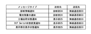
- FIG. 6 is a diagram showing an example of a message transmitted by the second request type sequence in the embodiment of the present invention.
- a message whose message type is “diagnosis information notification” is a message for notifying the wireless module 30 of diagnosis information that is a diagnosis result of the interface module 20.
- the message whose message type is “Notification of remaining battery level” is a message for notifying the wireless module 30 of the remaining battery level of the power source 29.
- the source of these messages is the diagnostic unit 24 of the interface module 20, and the destination of these messages is the wireless communication unit 33 of the wireless module 30.
- the messages whose message types are “factory shipment state notification”, “DIP Switch state change notification”, and “display unit full display state notification” indicate various states of each part of the interface module 20 that can be displayed on the display unit 25 as wireless modules.
- 30 is a message to be notified.
- the transmission source of these messages is the display unit 25 of the interface module 20, and the transmission destination of these messages is the wireless communication unit 33 of the wireless module 30.
- the message processing sequence between the interface module 20 and the wireless module 30 provided in the wireless device 12 is (1) request / response type sequence, (2) first request type sequence, and (3) second. Contains a request type sequence. For this reason, below, operation
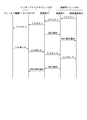
- FIG. 7 is a timing chart showing an example of the operation of the wireless device 12 when a request / response type sequence is performed in an embodiment of the present invention. Note that the timing chart shown in FIG. 7 shows an operation when the wireless device 12 acquires the measurement data of the field device 11. This operation is started when a control signal (control signal for instructing acquisition of measurement data) transmitted from the monitoring control device 16 via the wireless network N1 is received by the wireless communication unit 33 of the wireless module 30. .
- a control signal control signal for instructing acquisition of measurement data
- a control signal received by the wireless communication unit 33 of the wireless module 30 is output to the controller 32.
- the controller 32 generates data consisting of the third to sixth fields from the top of the data message M0 in FIG. Specifically, data in which the following information is stored in the third to sixth fields from the top of the data message M0 is generated.
- the created data is output from the controller 32 to the communication unit 31.
- a request field device control request
- the wireless communication unit 33 as a transmission source is transferred to the communication unit 31 as shown in FIG. It becomes.
- the communication unit 31 performs the above-described transmission message processing.
- FIG. 8 is a flowchart showing message processing at the time of transmission performed by the wireless device according to the embodiment of the present invention.
- the program for executing this flowchart may be stored in the storage unit 36, for example, or may be stored in another storage medium. 8 is performed each time data is output from the controller 32 to the communication unit 31, for example.
- the communication unit 31 executes the process shown in the flowchart shown in FIG.
- the transmission message process is started, the communication unit 31 first adds “MID” (message ID: see FIG. 3) to the head of the data from the controller 32 (step S11).
- the communication unit 31 performs special character processing (step S12).
- special character processing means that special data used in “STX” or “ETX”, which is information indicating the start or end of a message, is included in the data from the controller 32. This process replaces a character with another character.
- the communication unit 31 adds “STX” to the head of the data (step S13).
- the communication unit 31 calculates CRC information using the data before the “STX” is added, and the data of which the process of step S13 has been performed (the data with “STX” added to the head) is performed. “CRC” is added to the end (step S14).
- the communication unit 31 adds “ETX” to the end of the data subjected to the process of step S14 (data with “CRC” added to the end) (step S15).
- the message type “field device control request” is stored in the fourth field “M / H”, and the control signal from the monitoring controller 16 is stored in the sixth field “DATA”.
- a message (message having the same format as the data message M0 shown in FIG. 3) is generated.
- the communication unit 31 transmits the generated message to the communication unit 23 of the interface module 20 (step S16).
- a request having the wireless communication unit 33 as a transmission source is transmitted from the communication unit 31 to the communication unit 23 (transmission step).
- the communication unit 31 determines whether there is a transmission error (step S17). Specifically, the communication unit 31 determines whether or not there is an error such as an error in the physical layer or a retransmission failure.
- the communication unit 31 When it is determined that there is no transmission error (when the determination result is “NO”), the communication unit 31 ends the series of message processing during transmission illustrated in FIG. On the other hand, when it is determined that there is a transmission error (when the determination result is “YES”), the communication unit 31 performs error processing (step S18). Specifically, the communication unit 31 interrupts the transmission process and returns to the initial state (the state before the process of step S11 is performed).
- FIG. 9 is a flowchart showing message processing at the time of reception performed by the wireless device according to the embodiment of the present invention.
- the program for executing this flowchart may be stored in the storage unit 28, for example, or may be stored in another storage medium.
- the flowchart shown in FIG. 9 is performed each time a message from the communication unit 31 is received, for example.
- the communication unit 23 When the message processing at the time of reception is started, the communication unit 23 first determines whether there is a reception error (step S21). Specifically, the communication unit 23 determines whether there is an error in the physical layer such as a framing error, an error between characters, a frame reception timeout, or the like. When it is determined that there is no reception error (when the determination result is “NO”), the communication unit 23 deletes “STX” added to the head of the received message (step S22). Subsequently, the communication unit 23 deletes “ETX” added to the end of the received message (step S23).
- the communication unit 23 determines whether there is a CRC error (step S24). Specifically, the communication unit 23 first calculates CRC information using data (see data message M0 in FIG. 3) stored in the second to sixth fields from the beginning of the received message. Then, the communication unit 23 collates the calculated CRC information with the CRC information stored in the seventh field of the received message.
- the communication unit 23 When it is determined that there is no CRC error (when the determination result in step S24 is “NO”), the communication unit 23 performs special character processing (step S25).
- the special character process is a process of restoring the character replaced in the special character process performed in the transmission message process described with reference to FIG. 8 to the original special character.
- the communication unit 23 stores “MID” (message ID) added to the received message (step S26).
- step S26 is performed differently when a request is received and when a response is received.
- the communication unit 23 since it is a case where the request from the wireless module 30 is received, the communication unit 23 stores the message ID as described above.
- the communication unit 23 collates the message ID added to the response message with the message ID previously stored at the time of request transmission.
- the communication unit 23 omits the process of Step S27 (the process of determining the collation error).
- the communication part 23 performs the process of step S27, when a response is received.
- step S28 processing for transferring data obtained by the above processing (data consisting of the third to sixth fields from the top of the data message M0 in FIG. 3) is performed (step S28). If it is determined in step S21 that there is a reception error, if it is determined in step S24 that there is a CRC error, or if it is determined in step S27 that there is a collation error (any of steps S21, S24, S27). If the determination result is “YES”), the communication unit 23 performs error processing (step S29). Specifically, the communication unit 23 interrupts the process and returns to the initial state (the state before the process of step S21 is performed).
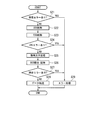
- FIG. 10 is a flowchart showing details of the data transfer process performed in step S28 in FIG.
- the program for executing this flowchart may be stored in the storage unit 28, for example, or may be stored in another storage medium.
- the flowchart shown in FIG. 10 is performed each time data processed by the communication unit 23 is input to the controller 22, for example.
- the controller 22 first stores “S / D” included in the data from the communication unit 23 (step S31). This process is performed to prepare for a response to a request from the wireless module 30.
- step S32 the controller 22 analyzes “M / H” included in the data from the communication unit 23 and determines the type of data included in the message from the wireless module 30 (step S32). Subsequently, the controller 22 performs processing according to the analysis result of step S32 (step S33).
- step S33 since the message type “field device control request” is stored in the message from the wireless module 30, the controller 22 transfers the data from the communication unit 23 to the sensor I / F 21 (see FIG. 4). ).
- a request (field device control request) with the wireless communication unit 33 as a transmission source is transferred to the sensor I / F 21.
- the request transferred to the sensor I / F 21 is transmitted to the field device 11 as shown in FIG. Then, measurement data as a response to the request is transmitted from the field device 11 to the sensor I / F 21. Measurement data (response) received by the sensor I / F 21 is input to the controller 22.
- the controller 22 generates data consisting of the third to sixth fields from the top of the data message M0 in FIG. 3 (step S34). Specifically, the controller 22 generates data in which the following information is stored in the third to sixth fields from the top of the data message M0.
- the information stored in the third field shown below is the transmission source of “S / D” stored in preparation for the response to the request from the wireless module 30 in the process of step S31 in FIG. This is information in which the transmission destination is replaced.
- the controller 22 When the above data is created, the controller 22 outputs the created data to the communication unit 23.
- a response (field device control response) having the sensor I / F 21 as a transmission source is transferred to the communication unit 23 as shown in FIG. It becomes.
- the communication unit 23 When data from the controller 22 is input, the communication unit 23 performs processing similar to the transmission message processing described with reference to FIG. 8, and a message to be returned to the wireless module 30 is generated. As a result, a message having the same format as the message transmitted from the wireless module 30 and received by the communication unit 23 is generated.
- the communication unit 23 transmits the generated message to the communication unit 31 of the wireless module 30 (reply step).
- a response having the sensor I / F 21 as a transmission source is transmitted from the communication unit 23 to the communication unit 31.
- the communication unit 31 receives a message from the communication unit 23, the communication unit 31 performs processing similar to the message processing at the time of reception described with reference to FIG.
- the reception message processing performed here is reception message processing for a response. For this reason, the communication unit 31 performs collation processing (step S26) and determines the presence or absence of a collation error (step S27).
- Data obtained by the message processing at the time of reception is output from the communication unit 31 to the controller 32.
- the controller 32 since the message type “field device control response” is stored in the data input from the communication unit 31 to the controller 32, the controller 32 sends data from the communication unit 31 to the wireless communication unit 33. Is transferred (see FIG. 4). Thereby, as shown in FIG. 7, the response received by the communication unit 31 is transferred to the wireless communication unit 33.
- the data transferred to the wireless communication unit 33 (data including the measurement data of the field device 11) is transmitted to the monitoring control device 16 via the wireless network N1. In this way, the measurement data of the field device 11 is collected by the monitoring control device 16 based on the control signal from the monitoring control device 16.
- the wireless module 30 transmits a request to the interface module 20 and the interface module 20 returns a response to the wireless module 30 has been described. Contrary to this example, when the interface module 20 transmits a request to the wireless module 30 and the wireless module 30 returns a response to the interface module 20, the same operation as described above is performed.
- the interface module 20 and the wireless module 30 set the message type included in the returned message as a processing response. Further, when the message type included in the received message is a processing request for the own module, the interface module 20 and the wireless module 30 include the processing result of the processing performed in response to the processing request in the message to be returned. .
- FIG. 11 is a timing chart illustrating an example of the operation of the wireless device 12 when the first request type sequence is performed in an embodiment of the present invention. Note that the timing chart shown in FIG. 11 shows an operation in the case where, for example, the wireless module 30 issues a display notification to the interface module 20 (here, “radio state display notification”).
- the created data is output from the controller 32 to the communication unit 31.
- a request radio state display notification
- the wireless communication unit 33 as a transmission source is transferred to the communication unit 31.
- processing similar to the transmission message processing described with reference to FIG. 8 is performed by the communication unit 31, and a message to be transmitted to the interface module 20 is generated.
- processing for transmitting the generated message to the communication unit 23 of the interface module 20 is performed.
- a request having the wireless communication unit 33 as a transmission source is transmitted from the communication unit 31 to the communication unit 23.
- the communication unit 23 performs the same processing as the message processing at the time of reception described with reference to FIG.
- the ACK message M11 (see FIG. 3) is sent from the communication unit 23 to the communication unit 31 in the case of normal reception.
- a NACK message M12 (see FIG. 3) is returned from the communication unit 23 to the communication unit 31.
- the communication unit 31 receives the ACK message M11 or the NACK message M12, the wireless communication unit 33 is notified to that effect.
- Data obtained by the message processing at the time of reception is output from the communication unit 23 to the controller 22.
- the controller 22 since the message type “radio state display notification” is stored in the data input from the communication unit 23 to the controller 22, the controller 22 sends the data from the communication unit 23 to the display unit 25. It transfers to the display part 25 (refer FIG. 5). Thereby, as shown in FIG. 11, the request received by the communication unit 23 is transferred to the display unit 25. In this way, information indicating the wireless state of the wireless module 30 is displayed on the display unit 25 of the interface module 20. As shown in FIG. 11, in the first request type sequence, the interface module 20 that has received a request from the wireless module 30 does not return a response to the wireless module 30.
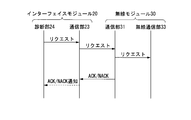
- FIG. 12 is a timing chart illustrating an example of the operation of the wireless device 12 when the second request type sequence is performed in an embodiment of the present invention. Note that the timing chart shown in FIG. 12 shows an operation when the interface module 20 notifies the wireless module 30 of the remaining battery level, for example.
- the controller 22 When the above data is created by the controller 22, the controller 22 outputs the created data to the communication unit 23. As a result, as shown in FIG. 12, a request (notification of remaining battery power) having the diagnosis unit 24 as a transmission source is transferred to the communication unit 23.
- the communication unit 23 When data from the controller 22 is input, the communication unit 23 performs processing similar to the message processing at the time of transmission described with reference to FIG. 8, and a message to be transmitted to the wireless module 30 is generated.
- processing for transmitting the generated message to the communication unit 31 of the wireless module 30 is performed.
- a request having the diagnosis unit 24 as a transmission source is transmitted from the communication unit 23 to the communication unit 31.
- the communication unit 31 receives a message from the communication unit 23, the communication unit 31 performs processing similar to the message processing at the time of reception described with reference to FIG.
- Data obtained by the message processing at the time of reception is output from the communication unit 31 to the controller 32.
- the controller 32 since the data input from the communication unit 31 to the controller 32 stores a message type “notification of remaining battery power”, the controller 32 sends a message from the communication unit 31 to the wireless communication unit 33. Data is transferred (see FIG. 6). Thereby, as shown in FIG. 12, the request received by the communication unit 31 is transferred to the wireless communication unit 33. In this way, information indicating the remaining amount of the power source 29 (battery) of the interface module 20 is transmitted to the wireless module 30. As shown in FIG. 12, in the second request type sequence, the wireless module 30 that has received a request from the interface module 20 does not return a response to the interface module 20.
- the wireless module 30 generates a message in a predetermined format including data to be transmitted to the interface module 20 and a message type, and transmits the generated message to the interface module 20. Then, the interface module 20 includes data and a message type to be returned to the wireless module 30 according to the message type included in the received message, generates a message in the same format as the received message, and sends it to the wireless module 30. I try to reply.
- the interface module 20 generates a message in a predetermined format including the data and message type to be transmitted to the wireless module 30 and transmits them to the wireless module 30. Then, the wireless module 30 includes data and message type to be returned to the interface module 20 according to the message type included in the received message, generates a message in the same format as the received message, and sends it to the interface module 20. I try to reply.
- the notification / command from the wireless module 30 to the interface module 20 and the notification / command from the interface module 20 to the wireless module 30 are performed using a message having the same format as the above message. I have to.
- messages in a unified format are transmitted and received between the interface module 20 and the wireless module 30.
- the interface module 20 and the wireless module 30 can be easily designed and developed.
- the field device 11 can be operated as a wireless field device that performs stable wireless communication.
- FIG. 13 is a diagram illustrating an application example of a wireless communication system in which a wireless device according to an embodiment of the present invention is used.
- a wireless communication system 2 shown in FIG. 13 is a communication system capable of allowing field devices 11a and 11b mounted with different communication protocols to enter the wireless network N1.
- the field devices 11a and 11b are similar to the field device 11 shown in FIG. 1, but different communication protocols are mounted on the field devices 11a and 11b.
- the field device 11a is implemented with a communication protocol compliant with HART (registered trademark).
- a communication protocol compliant with MODBUS (registered trademark) is implemented in the field device 11b.
- the interface modules 20a and 20b are the same as the interface module 20 shown in FIG.
- a communication protocol capable of communicating with the field device 11a is installed in the interface module 20a.
- a communication protocol capable of communicating with the field device 11b is mounted on the interface module 20b.
- a communication protocol compliant with HART registered trademark
- MODBUS registered trademark
- the monitoring control device 17 is the same as the monitoring control device 16 shown in FIG. 1, but can communicate with both the field devices 11a and 11b. That is, the supervisory control device 17 can transmit a control signal defined by HART (registered trademark) and a control signal defined by MODBUS (registered trademark).
- HART registered trademark
- MODBUS registered trademark
- various field devices 11a and 11b can enter the wireless network N1.
- the field devices 11a and 11b can be controlled without being aware of the route to the field devices 11a and 11b.
- the wireless device, the wireless communication system, the wireless module, the interface module, and the communication method according to the embodiment of the present invention have been described above.
- the present invention is not limited to the above-described embodiment and is within the scope of the present invention. It can be changed freely.
- a wireless device that performs wireless communication conforming to ISA100.11a has been described as an example.
- the present invention is also applicable to a wireless communication device that performs wireless communication conforming to WirelessHART (registered trademark). be able to.
Landscapes
- Engineering & Computer Science (AREA)
- Computer Networks & Wireless Communication (AREA)
- Signal Processing (AREA)
- Automation & Control Theory (AREA)
- Health & Medical Sciences (AREA)
- Computing Systems (AREA)
- General Health & Medical Sciences (AREA)
- Medical Informatics (AREA)
- Physics & Mathematics (AREA)
- General Physics & Mathematics (AREA)
- Selective Calling Equipment (AREA)
- Mobile Radio Communication Systems (AREA)
- Arrangements For Transmission Of Measured Signals (AREA)
- Programmable Controllers (AREA)
Abstract
無線機器(12)は、無線モジュール(30)と、インターフェイスモジュール(20)とを備える。無線モジュール(30)及びインターフェイスモジュール(20)の何れか一方は、無線モジュール(30)及びインターフェイスモジュール(20)の何れか他方へ送信すべきデータ及び該データの種別を示す種別情報が含まれる予め規定されたフォーマットの第1のメッセージを生成し、第1のメッセージを無線モジュール(30)及びインターフェイスモジュール(20)の何れか他方へ送信する。無線モジュール(30)及びインターフェイスモジュール(20)の何れか他方は、第1のメッセージに含まれる種別情報に応じて、無線モジュール(30)及びインターフェイスモジュール(20)の何れか一方へ返信すべきデータ及び該データの種別を示す種別情報が含まれた第1のメッセージと同じフォーマットの第2の メッセージを生成し、第2のメッセージを無線モジュール(30)及び前記インターフェイスモジュール(20)の何れか一方へ返信する。
Description
本発明は、無線機器、無線通信システム、無線モジュール、インターフェイスモジュール、及び通信方法に関する。
本願は、2013年10月24日に、日本に出願された特願2013-221442号に基づき優先権を主張し、その内容をここに援用する。
本願は、2013年10月24日に、日本に出願された特願2013-221442号に基づき優先権を主張し、その内容をここに援用する。
従来から、プラントや工場等においては、高度な自動操業を実現すべく、フィールド機器と呼ばれる現場機器(測定器、操作器)と、これらの制御を行う制御装置とが通信手段を介して接続された分散制御システム(DCS:Distributed Control System)が構築されている。このような分散制御システムを構成するフィールド機器は、有線通信を行っていた。しかし、近年においては、ISA100.11aやWirelessHART(登録商標)等の産業用無線通信規格に準拠した無線通信を行う無線フィールド機器が実現されている。
上記の無線フィールド機器は、概して工業プロセスにおける状態量(例えば、圧力、温度、流量等)の測定又は操作を行う入出力部と、上記の産業用無線通信規格に準拠した無線通信を行う無線通信部と、無線フィールド機器の動作を統括して制御する制御部とが筐体内に組み込まれている。また、無線フィールド機器は、単一の電源から供給される電力によって、上記の無線フィールド機器内部の各部が動作する。ここで、無線フィールド機器は、従来のフィールド機器のように通信線又は通信バスに接続する必要がなく、基本的に単独でプラント等に設置される。このことから、無線フィールド機器は、上記の単一の電源として電池を内蔵している。
以下の特許文献1には、無線通信部を有しない従来のフィールド機器に取り付けられて、従来のフィールド機器を上記の無線フィールド機器として動作させることが可能な無線機器が開示されている。具体的に、以下の特許文献1に開示された無線機器は、従来のフィールド機器に接続されるインターフェイス部と、無線通信を行う無線通信部と、インターフェイス部を介して従来のフィールド機器に電力を供給する電源部とを備える。この無線機器は、フィールド機器からの信号がインターフェイス部を介して入力されてきた場合には、その信号を無線通信部から送信先(例えば、上位のコントローラ)に向けて送信する。また、無線機器は、フィールド機器宛ての信号を無線通信部で受信した場合には、受信した信号をインターフェイス部を介してフィールド機器に出力する。
ところで、上述した特許文献1等に開示された無線機器は、フィールド機器の近くに設置される。これは、無線機器とフィールド機器とを接続する接続線を保護するための配管(コンジット)の設置工事を省略してコストの発生を抑える等の理由からである。しかしながら、フィールド機器は、パイプや生産設備等が多数設置されて電波の反射や遮蔽が生じやすい環境下に設置されることが多い。このため、上述した特許文献1に開示された無線機器のように、インターフェイス部と無線通信部とが一体化された構成では、安定した無線通信が困難になる可能性がある。
そこで、近年では、安定した無線通信を実現すべく、上記のインターフェイス部と無線通信部とを分離した無線機器の開発が行われている。具体的に、この無線機器は、上記のインターフェイス部を備えるインターフェイスモジュールと、上記の無線通信部を備える無線モジュールとの2つのモジュールに分けて構成される。また、これら2つのモジュールは、通信ケーブルによって接続される。このような構成の無線機器は、フィールド機器に接続されるインターフェイスモジュールから無線モジュールを離間させることができ、無線モジュールの設置位置の自由度を高めることができる。このため、無線モジュールを電波状況が良好な位置に設置すれば、安定した無線通信を実現することができる。
ここで、上述した特許文献1に開示された無線機器は、インターフェイス部及び無線通信部が一体化されており、1つのメーカーで製造されるものである。このため、フィールド機器を制御するために用いられる制御プロトコル(インターフェイス部とフィールド機器との間で用いられる制御プロトコル)は、フィールド機器の仕様に準拠したものであるが、内部制御に用いられる制御プロトコル(例えば、インターフェイス部と無線通信部との間で用いられる制御プロトコル)は独自の仕様のものが用いられている。
しかしながら、上述した2つのモジュールから構成される無線機器は、各々のモジュールが異なるメーカーにより別々に製造されることもある。このため、特許文献1に開示された無線機器のように、内部制御に用いられる制御プロトコル(モジュール間で用いられる制御プロトコル)が独自の仕様のものであると、各モジュールの設計・開発が困難になるとともに、困難であるがゆえに設計ミスが生じる虞がある。設計ミスが機器の実際の運用中に現れた場合、フィールド機器を上述の安定した無線通信を行う無線フィールド機器として動作させることができなくなる虞がある。
上記課題を解決するために、本発明の無線機器は、フィールド機器からの信号を無線で送信し、前記フィールド機器への信号を無線で受信する無線モジュールと、前記無線モジュールと前記フィールド機器との間に介在するインターフェイスモジュールとを備えており、前記無線モジュール及び前記インターフェイスモジュールの何れか一方は、前記無線モジュール及び前記インターフェイスモジュールの何れか他方へ送信すべきデータ及び該データの種別を示す種別情報が含まれる予め規定されたフォーマットの第1のメッセージを生成し、前記第1のメッセージを前記無線モジュール及び前記インターフェイスモジュールの何れか他方へ送信し、前記無線モジュール及び前記インターフェイスモジュールの何れか他方は、前記第1のメッセージに含まれる前記種別情報に応じて、前記無線モジュール及び前記インターフェイスモジュールの何れか一方へ返信すべきデータ及び該データの種別を示す種別情報が含まれた前記第1のメッセージと同じフォーマットの第2のメッセージを生成し、前記第2のメッセージを前記無線モジュール及び前記インターフェイスモジュールの何れか一方へ返信する。
また、本発明の無線機器において、前記無線モジュール及び前記インターフェイスモジュールの何れか他方は、前記第1のメッセージに含まれる前記種別情報が処理要求である場合には、前記種別情報を処理応答として前記第2のメッセージに含ませてもよい。
また、本発明の無線機器において、前記無線モジュール及び前記インターフェイスモジュールの何れか他方は、前記第1のメッセージに含まれる前記種別情報が自モジュールに対する処理要求である場合には、該処理要求に応じて行った処理の処理結果を前記返信すべきデータとして前記第2のメッセージに含ませてもよい。
また、本発明の無線機器において、前記無線モジュールから前記インターフェイスモジュールへ送信される前記第1のメッセージに含まれる前記種別情報としての処理要求には、前記フィールド機器への制御要求が含まれ、前記インターフェイスモジュールから前記無線モジュールへ返信される前記第2のメッセージに含まれる前記種別情報としての処理応答には、前記フィールド機器からの制御応答が含まれてもよい。
また、本発明の無線機器において、前記無線モジュール及び前記インターフェイスモジュールの何れか他方は、前記第1のメッセージに含まれる前記種別情報が通知又は指令である場合には、該通知又は指令に応じた処理を行って、前記無線モジュール及び前記インターフェイスモジュールの何れか一方への返信を行わなくてもよい。
また、本発明の無線機器において、前記インターフェイスモジュールは表示部を備え、前記無線モジュールから前記インターフェイスモジュールへ送信される前記第1のメッセージに含まれる前記種別情報としての処理要求には、前記無線モジュールの無線状態を示す情報を前記表示部に表示させるための無線状態表示通知が含まれ、前記インターフェイスモジュールは、前記無線状態表示通知についての前記第1のメッセージを受信しても、前記無線モジュールへ前記第2のメッセージを返信しなくてもよい。
また、本発明の無線機器において、前記インターフェイスモジュールは電池を備え、前記インターフェイスモジュールから前記無線モジュールへ送信される前記第1のメッセージに含まれる前記種別情報としての処理要求には、前記電池の残量を知らせるための電池残量通知が含まれ、前記無線モジュールは、前記電池残量通知についての前記第1のメッセージを受信しても、前記インターフェイスモジュールへ前記第2のメッセージを返信しなくてもよい。
また、本発明の無線機器において、前記無線モジュールは、無線で通信する無線通信部と、前記インターフェイスモジュールと通信する第1の通信部と、前記無線通信部及び前記第1の通信部を制御する第1のコントローラと、を更に備えてもよい。
また、本発明の無線機器において、前記第1のコントローラは、前記第1のメッセージの送信元及び送信先を示す情報と、前記種別情報と、前記インターフェイスモジュールへ送信すべきデータのサイズを示す情報と、前記インターフェイスモジュールへ送信すべきデータと、を含むデータを生成してもよい。
また、本発明の無線機器において、前記第1の通信部は、前記第1のコントローラによって生成された前記データに、前記第1のメッセージの開始を示す情報と、前記第1のメッセージのIDと、送受信のエラーチェックに用いられる情報と、前記第1のメッセージの終了を示す情報と、を付加することにより前記第1のメッセージを生成し、生成した前記第1のメッセージを前記インターフェイスモジュールへ送信してもよい。
また、本発明の無線機器において、前記インターフェイスモジュールは、前記フィールド機器と通信するセンサI/Fと、前記無線モジュールと通信する第2の通信部と、前記センサI/F及び前記第2の通信部を制御する第2のコントローラと、を更に備えてもよい。
また、本発明の無線機器において、前記第2の通信部は、前記無線モジュールから受信した前記第1のメッセージから、前記第1のメッセージの開始を示す情報と、前記第1のメッセージの終了を示す情報と、を削除してもよい。
また、本発明の無線機器において、前記第2の通信部は、前記無線モジュールから受信した前記第1のメッセージに含まれる前記送受信のエラーチェックに用いられる情報に基づき、エラーの有無を判断してもよい。
また、本発明の無線機器において、前記第2の通信部によって前記エラーが無いと判断された場合、前記第2のコントローラは、前記第1のメッセージに含まれる前記種別情報を解析し、解析結果に応じた処理を行ってもよい。
また、本発明の無線機器において、前記インターフェイスモジュールは、第1のフィールド機器と通信する第1のインターフェイスモジュールと、前記第1のフィールド機器とは異なる通信プロトコルが実装された第2のフィールド機器と通信する第2のインターフェイスモジュールと、を備え、前記無線モジュールは、前記第1のインターフェイスモジュールと通信する第1の無線モジュールと、前記第2のインターフェイスモジュールと通信する第2の無線モジュールと、を備えてもよい。
また、本発明の無線モジュールは、第1のメッセージを外部から無線で受信するとともに、第2のメッセージを外部へ無線で送信する通信部と、外部へ送信すべきデータ及び該データの種別を示す種別情報が含まれる予め規定されたフォーマットの前記第2のメッセージを前記通信部から外部へ送信させる制御部とを備える。
また、本発明の無線モジュールにおいて、前記制御部は、前記第1のメッセージに含まれる前記種別情報に応じて、外部へ返信すべきデータ及び該データの種別を示す種別情報が含まれ、前記第1のメッセージと同じフォーマットの前記第2のメッセージを前記通信部から外部へ返信させてもよい。
また、本発明のインターフェイスモジュールは、第1のメッセージを無線モジュールから無線で受信するとともに、第2のメッセージを前記無線モジュールへ無線で送信する通信部と、前記第1のメッセージに含まれる種別情報に応じて、前記無線モジュールへ返信すべきデータ及び該データの種別を示す種別情報が含まれ、前記第1のメッセージと同じフォーマットの前記第2のメッセージを前記通信部から前記無線モジュールへ返信させる制御部とを備える。
また、本発明のインターフェイスモジュールにおいて、前記制御部は、前記無線モジュールへ送信すべきデータ及び該データの種別を示す種別情報が含まれる予め規定されたフォーマットの第3のメッセージを前記通信部から前記無線モジュールへ送信させてもよい。
また、本発明の通信方法は、無線で信号の送受信を行う無線モジュールと、該無線モジュールとフィールド機器との間に介在するインターフェイスモジュールとの間の通信方法であって、前記無線モジュール及び前記インターフェイスモジュールの何れか一方が、前記無線モジュール及び前記インターフェイスモジュールの何れか他方へ送信すべきデータ及び該データの種別を示す種別情報が含まれる予め規定されたフォーマットの第1のメッセージを生成し、前記無線モジュール及び前記インターフェイスモジュールの何れか一方が、前記第1のメッセージを前記無線モジュール及び前記インターフェイスモジュールの何れか他方へ送信し、前記無線モジュール及び前記インターフェイスモジュールの何れか他方が、前記第1のメッセージに含まれる前記種別情報に応じて、前記無線モジュール及び前記インターフェイスモジュールの何れか一方へ返信すべきデータ及び該データの種別を示す種別情報が含まれ、前記第1のメッセージと同じフォーマットの第2のメッセージを生成し、前記無線モジュール及び前記インターフェイスモジュールの何れか他方が、前記第2のメッセージを前記無線モジュール及び前記インターフェイスモジュールの何れか一方へ返信してもよい。
本発明によれば、設計・開発が容易であって安定した無線通信を行うことが可能な無線機器、無線通信システム、無線モジュール、インターフェイスモジュールを提供することができるという効果がある。
本発明のいくつかの実施形態は、設計・開発が容易であって安定した無線通信を行うことが可能な無線機器、無線通信システム、無線モジュール、インターフェイスモジュール、及び通信方法を提供することを目的とする。
以下、図面を参照して本発明の一実施形態による無線機器、無線通信システム、無線モジュール、インターフェイスモジュール、及び通信方法について詳細に説明する。
〈無線通信システム〉
図1は、本発明の一実施形態による無線機器が用いられる無線通信システムの全体構成を示すブロック図である。図1に示す通り、無線通信システム1は、フィールド機器11、無線機器12、バックボーンルータ13、システムマネージャ14、ゲートウェイ15、及び監視制御装置16を備えている。無線通信システム1は、無線ネットワークN1を介した無線通信が可能である。この無線通信システム1は、例えばプラントや工場等(以下、これらを総称する場合には、単に「プラント」という)に構築される。
図1は、本発明の一実施形態による無線機器が用いられる無線通信システムの全体構成を示すブロック図である。図1に示す通り、無線通信システム1は、フィールド機器11、無線機器12、バックボーンルータ13、システムマネージャ14、ゲートウェイ15、及び監視制御装置16を備えている。無線通信システム1は、無線ネットワークN1を介した無線通信が可能である。この無線通信システム1は、例えばプラントや工場等(以下、これらを総称する場合には、単に「プラント」という)に構築される。
ここで、無線通信システム1が構築されるプラントには、無線ネットワークN1、バックボーンネットワークN2、及び制御ネットワークN3が設けられている。無線ネットワークN1は、プラントの現場に設置されたフィールド機器11に接続される無線機器12及びバックボーンルータ13によって実現される。無線ネットワークN1は、システムマネージャ14によって管理されるネットワークである。尚、無線ネットワークN1を構成する無線機器12及びバックボーンルータ13の数は任意である。
バックボーンネットワークN2は、無線通信システム1の基幹となる有線ネットワークである。バックボーンネットワークN2には、バックボーンルータ13、システムマネージャ14、及びゲートウェイ15が接続される。制御ネットワークN3は、バックボーンネットワークN2の上位に位置づけられる有線ネットワークである。制御ネットワークN3には、ゲートウェイ15及び監視制御装置16が接続される。
フィールド機器11は、プラントの現場に設置される。フィールド機器11は、監視制御装置16の制御の下で工業プロセスの制御に必要な測定及び操作の少なくとも一方を行う。具体的に、フィールド機器11は、例えば流量計や温度センサ等のセンサ機器、流量制御弁や開閉弁等のバルブ機器、ファンやモータ等のアクチュエータ機器、プラント内の状況や対象物を撮影するカメラやビデオ等の撮像機器、プラント内の異音等を収集したり警報音等を発したりするマイクやスピーカ等の音響機器、各機器の位置情報を出力する位置検出機器、その他の機器である。尚、以下では理解を容易にするために、フィールド機器11が流体の流量を測定するセンサ機器であるものとして説明する。
無線機器12は、フィールド機器11に接続されるインターフェイスモジュール20と、インターフェイスモジュール20に接続されて無線ネットワークN1を介した無線信号の送受信を行う無線モジュール30とを備える。尚、無線モジュール30は、ISA100.11aに準拠した無線通信が可能である。この無線機器12は、無線通信機能を有しないフィールド機器11に接続されて、フィールド機器11からの信号を無線信号にして無線ネットワークN1に送信する。また、無線機器12は、無線ネットワークN1を介して無線信号で送信されてくるフィールド機器11への信号を受信する。尚、無線機器12が備えるインターフェイスモジュール20及び無線モジュール30の詳細については後述する。
バックボーンルータ13は、無線ネットワークN1とバックボーンネットワークN2とを接続する。また、バックボーンルータ13は、無線ネットワークN1とバックボーンネットワークN2との間で送受信されるデータの中継を行う。尚、このバックボーンルータ13は、上述した無線機器12が備える無線モジュール30と同様に、無線通信規格ISA100.11aに準拠した無線通信が可能である。
システムマネージャ14は、無線ネットワークN1を介して行われる無線通信の制御を行う。具体的には、無線機器12に設けられた無線モジュール30、バックボーンルータ13、及びゲートウェイ15に対する通信リソース(タイムスロット及びチャネル)の割り当て制御を行って、無線ネットワークN1を介した無線通信を実現する。尚、システムマネージャ14は、無線ネットワークN1に対して無線機器12を参入させる処理も行う。
ゲートウェイ15は、バックボーンネットワークN2と制御ネットワークN3とを接続する。また、ゲートウェイ15は、フィールド機器11及びシステムマネージャ14等と、監視制御装置16との間で送受信される各種データの中継を行う。このゲートウェイ15を設けることで、セキュリティを維持しつつ、バックボーンネットワークN2と制御ネットワークN3とを相互に接続することができる。
監視制御装置16は、例えばプラントの運転員によって操作され、フィールド機器11等の監視及び管理を行う。具体的に、監視制御装置16は、ゲートウェイ15を介してフィールド機器11から測定データ(流量値)を収集することによってフィールド機器11等の監視を行う。また、監視制御装置16は、収集した測定データに基づいて不図示の他のフィールド機器の制御量(例えば、バルブ機器の弁開度)を求める。また、監視制御装置16は、求められたフィールド機器の制御量をゲートウェイ15を介して不図示の他のフィールド機器に設定し、操作することによって、フィールド機器11を制御する。
〈無線機器〉
図2は、本発明の一実施形態による無線機器の要部構成を示すブロック図である。以下、図2を参照して無線機器12に設けられたインターフェイスモジュール20及び無線モジュール30の内部構成を順に説明する。インターフェイスモジュール20は、センサI/F(インターフェイス)21、コントローラ22(制御部)、通信部23、診断部24、表示部25、設定部26、電源制御部27、格納部28、及び電源29を備える。かかる構成のインターフェイスモジュール20は、無線モジュール30とフィールド機器11との間に介在する。インターフェイスモジュール20は、無線モジュール30とフィールド機器11とを接続するためのインターフェイスである。
図2は、本発明の一実施形態による無線機器の要部構成を示すブロック図である。以下、図2を参照して無線機器12に設けられたインターフェイスモジュール20及び無線モジュール30の内部構成を順に説明する。インターフェイスモジュール20は、センサI/F(インターフェイス)21、コントローラ22(制御部)、通信部23、診断部24、表示部25、設定部26、電源制御部27、格納部28、及び電源29を備える。かかる構成のインターフェイスモジュール20は、無線モジュール30とフィールド機器11との間に介在する。インターフェイスモジュール20は、無線モジュール30とフィールド機器11とを接続するためのインターフェイスである。
センサI/F21は、フィールド機器11に接続される。センサI/F21は、コントローラ22の制御の下で、フィールド機器11からの信号を受信する。また、センサI/F21は、コントローラ22の制御の下で、フィールド機器11に向けて信号を送信する。つまり、センサI/F21には、フィールド機器11との間の通信を可能とするために、フィールド機器11に実装されている通信プロトコルと同じ通信プロトコルが実装されている。
コントローラ22は、インターフェイスモジュール20の動作を統括して制御する。例えば、コントローラ22は、無線モジュール30から送信されてくるメッセージに含まれる制御信号(監視制御装置16からの制御信号)に基づいてセンサI/F21を制御して、フィールド機器11で得られた測定データ(流量値)を取得させる。また、コントローラ22は、通信部23を制御して無線モジュール30との間でメッセージの送受信を行わせる。例えば、コントローラ22は、センサI/F21で取得された測定結果を無線モジュール30に送信させる。尚、詳細は後述するが、インターフェイスモジュール20と無線モジュール30との間で送受信されるメッセージは、予め規定されたフォーマットのメッセージである。
通信部23は、無線モジュール30から送信されてくるメッセージを受信する。また、通信部23は、無線モジュール30へメッセージを送信する。ここで、通信部23は、無線モジュール30からのメッセージを受信した場合には、受信したメッセージに対して予め規定されたメッセージ処理(受信時メッセージ処理)を行う。一方、通信部23は、無線モジュール30に送信すべきデータがコントローラ22から出力された場合には、そのデータに対して予め規定されたメッセージ処理(送信時メッセージ処理)を行う。尚、これら受信時メッセージ処理及び送信時メッセージ処理の詳細については後述する。
診断部24は、自己診断機能を備えており、コントローラ22の制御の下で自モジュール(インターフェイスモジュール20)の状態を診断する。例えば、診断部24は、インターフェイスモジュール20の故障の有無、フィールド機器11の接続状況、電源29の残量等を診断する。表示部25は、例えば液晶表示装置等の表示装置を備えている。表示部25は、コントローラ22の制御の下で各種情報を表示する。例えば、表示部25は、フィールド機器11から得られた測定データ(流量値)や、インターフェイスモジュール20或いは無線モジュール30の状態を示す情報を表示する。
設定部26は、外部機器が接続される外部インターフェイス(例えば、赤外線通信部)を備えている。設定部26は、外部機器からの指示に基づいて無線機器12に設定すべき情報の設定を行う。ここで、上記外部機器は、例えばプロビジョニングデバイスである。設定部26は、赤外線通信によってプロビジョニングデバイスから送信されてくるプロビジョニング情報(無線ネットワークN1に参入するために必要となる情報)の設定を行う。
電源制御部27は、電源29からの電力を、フィールド機器11、インターフェイスモジュール20、及び無線モジュール30に適した電力に変換する電源回路(図示省略)を備えている。電源制御部27は、コントローラ22の制御の下で、フィールド機器11、インターフェイスモジュール20の各部、及び無線モジュール30に電力を供給する。尚、フィールド機器11が電源を内蔵していたり、他の経路から電力供給を受ける場合には、電源制御部27はフィールド機器11に電力を供給しない。格納部28は、インターフェイスモジュール20を識別するための識別情報や、電源29の残量を示す情報を格納する。この格納部28は、例えばフラッシュROM(Read Only Memory)やEEPROM(Electrically Erasable and Programmable ROM)等の不揮発性メモリである。
電源29は、フィールド機器11、インターフェイスモジュール20、及び無線モジュール30を動作させるための電力源として、電力を供給する。ここで、電源29としては、電池(例えば、塩化チオニルリチウム電池等の自己放電が極めて少ない一次電池や二次電池)、燃料電池、キャパシタ、或いは環境発電(所謂、太陽電池等のエナジーハーベスト)を行う発電回路等を用いることができる。
無線モジュール30は、通信部31、コントローラ32(制御部)、無線通信部33、診断部34、電源制御部35、格納部36、及びアンテナATを備える。かかる構成の無線モジュール30は、インターフェイスモジュール20に接続される。無線モジュール30は、無線ネットワークN1を介した無線信号の送受信を行う。
通信部31は、インターフェイスモジュール20から送信されてくるメッセージを受信する。また、通信部31は、メッセージをインターフェイスモジュール20へ送信する。ここで、通信部31は、インターフェイスモジュール20の通信部23と同様の処理を行う。つまり、通信部31は、インターフェイスモジュール20からのメッセージを受信した場合には、受信したメッセージに対して予め規定された受信時メッセージ処理(詳細は後述する)を行う。一方、通信部31は、インターフェイスモジュール20に送信すべきデータがコントローラ32から出力された場合には、そのデータに対して予め規定された送信時メッセージ処理(詳細は後述する)を行う。
コントローラ32は、無線モジュール30の動作を統括して制御する。例えば、コントローラ32は、インターフェイスモジュール20からのメッセージに含まれるデータ(例えば、無線モジュール30を制御するための制御データ)に基づいて、無線モジュール30の各部を制御する。また、コントローラ32は、通信部31を制御してインターフェイスモジュール20との間でメッセージの送受信を行わせる。
無線通信部33は、コントローラ32の制御の下で、アンテナATを介して無線信号を無線ネットワークN1に送信する。また、無線通信部33は、コントローラ32の制御の下で、無線ネットワークN1を介して送信されてきてアンテナATを介した無線信号を受信する。この無線通信部33は、前述したISA100.11aに準拠した無線通信を行う。尚、アンテナATは無線モジュール30に収容される内部アンテナであっても、無線モジュール30の外部に設けられる外部アンテナであっても良い。診断部34は、自己診断機能を備えている。診断部34は、コントローラ32の制御の下で自モジュール(無線モジュール30)の状態を診断する。例えば、診断部34は、無線モジュール30の故障の有無等を診断する。
電源制御部35は、コントローラ32の制御の下で、インターフェイスモジュール20からの電力を無線モジュール30の各部に供給するか否かを制御する。電源制御部35がこのような制御を行うのは、インターフェイスモジュール20に設けられた電源29の電力消費を抑えるためである。格納部36は、無線モジュール30に設定される情報を格納する。この格納部36は、インターフェイスモジュール20に設けられる格納部28と同様の不揮発性メモリである。
〈メッセージのフォーマット〉
次に、無線機器12に設けられたインターフェイスモジュール20と無線モジュール30との間で送受信されるメッセージのフォーマットについて説明する。図3は、本発明の一実施形態による無線機器で送受信されるメッセージのフォーマットを示す図である。ここで、無線機器12のインターフェイスモジュール20と無線モジュール30との間で送受信されるメッセージは、図3に示す通り、データメッセージM0、ACKメッセージM11、及びNACKメッセージM12を含む。
次に、無線機器12に設けられたインターフェイスモジュール20と無線モジュール30との間で送受信されるメッセージのフォーマットについて説明する。図3は、本発明の一実施形態による無線機器で送受信されるメッセージのフォーマットを示す図である。ここで、無線機器12のインターフェイスモジュール20と無線モジュール30との間で送受信されるメッセージは、図3に示す通り、データメッセージM0、ACKメッセージM11、及びNACKメッセージM12を含む。
データメッセージM0は、インターフェイスモジュール20と無線モジュール30との間でデータの授受を行うためのメッセージである。データメッセージM0は、「STX」、「MID」、「S/D」、「M/H」、「D/S」、「DATA」、「CRC」、及び「ETX」が格納される8つのフィールドを含む。これに対し、ACKメッセージM11は、受信側モジュールが送信側モジュールに対して正常受信(肯定応答)を知らせるためのメッセージである。ACKメッセージM11は、データメッセージM0から「D/S」及び「DATA」が格納される2つのフィールドを除いた6つのフィールドを含む。また、NACKメッセージM12は、受信側モジュールが送信側モジュールに対して異常受信(否定応答)を知らせるためのメッセージである。NACKメッセージM12は、データメッセージM0の「D/S」及び「DATA」が格納されるフィールドに代えて「ErrCode」が格納されるフィールドが設けられた7つのフィールドを含む。
尚、図3中の「STX」、「MID」、「S/D」、「M/H」、「D/S」、「DATA」、「CRC」、「ETX」、及び「ErrCode」の意味は以下の通りである。
「STX」:メッセージの開始を示す情報
「MID」:メッセージの各々に付される識別子(メッセージID)
「S/D」:メッセージの送信元及び送信先を示す情報
「M/H」:「DATA」の種別又はACK/NACKを示す情報(種別情報)
「D/S」:「DATA」のサイズを示す情報
「DATA」:相手方モジュールに送信すべきデータ
「CRC」:送受信のエラーチェック(巡回冗長検査)に用いられる情報
「ETX」:メッセージの終了を示す情報
「ErrCode」:エラーコード
「STX」:メッセージの開始を示す情報
「MID」:メッセージの各々に付される識別子(メッセージID)
「S/D」:メッセージの送信元及び送信先を示す情報
「M/H」:「DATA」の種別又はACK/NACKを示す情報(種別情報)
「D/S」:「DATA」のサイズを示す情報
「DATA」:相手方モジュールに送信すべきデータ
「CRC」:送受信のエラーチェック(巡回冗長検査)に用いられる情報
「ETX」:メッセージの終了を示す情報
「ErrCode」:エラーコード
データメッセージM0、ACKメッセージM11、及びNACKメッセージM12の先頭の3つのフィールド(「STX」、「MID」、「S/D」が格納されるフィールド)及び末尾の2つのフィールド(「CRC」、「ETX」が格納されるフィールド)は、メッセージの送信時にインターフェイスモジュール20の通信部23又は無線モジュール30の通信部31で行われる送信時メッセージ処理で付加される。また、これらのフィールドは、メッセージの受信時にインターフェイスモジュール20の通信部23又は無線モジュール30の通信部31で行われる受信時メッセージ処理で削除される。
〈メッセージ処理シーケンス〉
インターフェイスモジュール20と無線モジュール30との間で、上述したメッセージを送受信するシーケンス(メッセージ処理シーケンス)は、以下の(1)~(3)に示すシーケンスを含む。
(1)リクエスト/レスポンス型シーケンス
(2)第1リクエスト型シーケンス
(3)第2リクエスト型シーケンス
インターフェイスモジュール20と無線モジュール30との間で、上述したメッセージを送受信するシーケンス(メッセージ処理シーケンス)は、以下の(1)~(3)に示すシーケンスを含む。
(1)リクエスト/レスポンス型シーケンス
(2)第1リクエスト型シーケンス
(3)第2リクエスト型シーケンス
上記(1)に示すリクエスト/レスポンス型シーケンスは、インターフェイスモジュール20及び無線モジュール30の何れか一方から送信された要求(リクエスト)に対するインターフェイスモジュール20及び無線モジュール30の何れか他方の応答(レスポンス)を伴うシーケンスである。これに対し、上記(2)に示す第1リクエスト型シーケンスは、無線モジュール30からインターフェイスモジュール20への要求(リクエスト)は送信されるものの、インターフェイスモジュール20からの応答(レスポンス)を伴わないシーケンスである。また、上記(3)に示す第2リクエスト型シーケンスは、インターフェイスモジュール20から無線モジュール30への要求(リクエスト)は送信されるものの、無線モジュール30からの応答(レスポンス)を伴わないシーケンスである。
図4は、本発明の一実施形態において、リクエスト/レスポンス型シーケンスにより送受信されるメッセージの一例を示す図である。図4に示す例において、メッセージタイプ(図3中の「M/H」)が「フィールド機器制御要求」であるメッセージは、フィールド機器11の制御を要求するメッセージである。このメッセージの送信元は無線モジュール30の無線通信部33であり、このメッセージの送信先はインターフェイスモジュール20のセンサI/F21である。例えば、フィールド機器制御要求には、フィールド機器11で測定された流量値の読み込み、フィールド機器11であるバルブの開度操作、フィールド機器11自体の調整等が含まれる。また、メッセージタイプが「フィールド機器制御応答」であるメッセージは、「フィールド機器制御要求」に対する応答のメッセージである。このメッセージの送信元はインターフェイスモジュール20のセンサI/F21であり、このメッセージの送信先は無線モジュール30の無線通信部33である。
また、メッセージタイプが「設定要求」であるメッセージは、無線モジュール30に設定すべき情報(例えば、プロビジョニング情報)の設定を要求するメッセージである。このメッセージの送信元はインターフェイスモジュール20の設定部26であり、このメッセージの送信先は無線モジュールの無線通信部33である。また、メッセージタイプが「設定応答」であるメッセージは、「設定要求」に対する応答のメッセージである。このメッセージの送信元は無線モジュール30の無線通信部33であり、このメッセージの送信先はインターフェイスモジュール20の設定部26である。
尚、メッセージタイプが「ファームウェア識別子取得要求」であるメッセージは、インターフェイスモジュール20で用いられているファームウェアの識別子の取得を要求するメッセージである。メッセージタイプが「ファームウェア識別子取得応答」であるメッセージは、「ファームウェア識別子取得要求」に対する応答を示すメッセージである。このメッセージによって、例えば診断部24において実行される診断機能の種類に応じて付されたファームウェアの識別子を確認すれば、インターフェイスモジュール20で実行される診断機能の種類を確認することができる。また、メッセージタイプが「格納部リード/ライト要求」であるメッセージは、インターフェイスモジュール20の格納部28に対するデータの読み出しや書き込みを要求するメッセージである。メッセージタイプが「格納部リード/ライト応答」であるメッセージは、その応答を示すメッセージである。
また、メッセージタイプが「センサI/Fファームウェア更新要求」であるメッセージは、インターフェイスモジュール20のセンサI/F21で用いられているファームウェアの更新を要求するメッセージである。メッセージタイプが「センサI/Fファームウェア更新応答」であるメッセージは、その応答を示すメッセージである。このメッセージによって、例えばセンサI/F21に実装されている通信プロトコルを更新(例えば、HART(登録商標)等に更新)し、或いはセンサI/F21で用いられているファームウェアを通信プロトコルのリビジョン番号に準拠したものに更新することができる。尚、これらのメッセージの送信元及び送信先は、図4に示す通りである。
図5は、本発明の一実施形態において、第1リクエスト型シーケンスにより送信されるメッセージの一例を示す図である。図5に示す例において、メッセージタイプが「無線モジュールの初期化完了通知」であるメッセージは、無線モジュール30で行われる初期化の完了をインターフェイスモジュール20に通知するメッセージである。また、メッセージタイプが「無線モジュールの停止準備完了通知」であるメッセージは、無線モジュール30で行われる停止準備の完了をインターフェイスモジュール20に通知するメッセージである。これらのメッセージの送信元は無線モジュール30の通信部31であり、これらのメッセージの送信先はインターフェイスモジュール20の通信部23である。
また、メッセージタイプが「フィールド機器の電源On/Off通知」であるメッセージは、フィールド機器11の電源オン/オフをインターフェイスモジュール20に通知(指令)するメッセージである。メッセージタイプが「フィールド機器の供給電源設定通知」であるメッセージは、フィールド機器11への電源供給の設定をインターフェイスモジュール20に通知(指令)するメッセージである。メッセージタイプが「センサI/Fのリセット通知」であるメッセージは、センサI/F21のリセットをインターフェイスモジュール20に通知(指令)するメッセージである。これらのメッセージの送信元は無線モジュール30の無線通信部33であり、これらのメッセージの送信先はインターフェイスモジュール20のセンサI/F21である。
また、メッセージタイプが「電池残量情報のリセット通知」であるメッセージは、電源29(電池)の残量情報のリセットをインターフェイスモジュール20に通知するメッセージである。メッセージタイプが「電池使用量の通知」であるメッセージは、無線モジュール30における電力使用量をインターフェイスモジュール20に通知するメッセージである。これらのメッセージの送信元は無線モジュール30の無線通信部33であり、これらのメッセージの送信先はインターフェイスモジュール20の診断部24である。
また、メッセージタイプが「無線状態表示通知」、「表示部共通設定変更通知」、「プロセス値表示設定通知」、「アラート表示通知」、「プロセス値表示通知」、「機器探索状態表示通知」、「表示部テスト状態表示通知」、「書き込み禁止状態表示通知」であるメッセージは、無線モジュール30が、無線状態、フィールド機器11の測定データ(プロセス値)、アラート等の各種情報を、インターフェイスモジュール20の表示部25に表示させる通知(指令)である。これらのメッセージの送信元は無線モジュール30の無線通信部33であり、これらのメッセージの送信先はインターフェイスモジュール20の表示部25である。
また、メッセージタイプが「無線モジュール状態通知」であるメッセージは、無線モジュール30の状態をインターフェイスモジュール20に通知するメッセージである。このメッセージの送信元は無線モジュール30の診断部34であり、このメッセージの送信先はインターフェイスモジュール20の診断部24である。
図6は、本発明の一実施形態において、第2リクエスト型シーケンスにより送信されるメッセージの一例を示す図である。図6に示す例において、メッセージタイプが「診断情報通知」であるメッセージは、インターフェイスモジュール20の診断結果である診断情報を無線モジュール30に通知するメッセージである。メッセージタイプが「電池残量の通知」であるメッセージは、電源29の電池残量を無線モジュール30に通知するメッセージである。これらのメッセージの送信元はインターフェイスモジュール20の診断部24であり、これらのメッセージの送信先は無線モジュール30の無線通信部33である。
また、メッセージタイプが「工場出荷状態通知」、「DIP Switch状態変更通知」、「表示部全表示状態通知」であるメッセージは、表示部25に表示可能なインターフェイスモジュール20各部の各種状態を無線モジュール30に通知するメッセージである。これらのメッセージの送信元はインターフェイスモジュール20の表示部25であり、これらのメッセージの送信先は無線モジュール30の無線通信部33である。
〈無線機器の動作〉
次に、無線機器12の動作について説明する。上述の通り、無線機器12に設けられたインターフェイスモジュール20と無線モジュール30との間におけるメッセージ処理シーケンスは、(1)リクエスト/レスポンス型シーケンス、(2)第1リクエスト型シーケンス、(3)第2リクエスト型シーケンスを含む。このため、以下ではこれら各メッセージ処理シーケンスが実施される場合の動作を順に説明する。
次に、無線機器12の動作について説明する。上述の通り、無線機器12に設けられたインターフェイスモジュール20と無線モジュール30との間におけるメッセージ処理シーケンスは、(1)リクエスト/レスポンス型シーケンス、(2)第1リクエスト型シーケンス、(3)第2リクエスト型シーケンスを含む。このため、以下ではこれら各メッセージ処理シーケンスが実施される場合の動作を順に説明する。
《リクエスト/レスポンス型シーケンスが実施される場合の動作》
図7は、本発明の一実施形態において、リクエスト/レスポンス型シーケンスが実施される場合の無線機器12の動作の一例を示すタイミングチャートである。尚、図7に示すタイミングチャートは、無線機器12がフィールド機器11の測定データを取得する場合の動作を示す。この動作は、監視制御装置16から無線ネットワークN1を介して送信されてきた制御信号(測定データの取得を指示する制御信号)が無線モジュール30の無線通信部33で受信されることにより開始される。
図7は、本発明の一実施形態において、リクエスト/レスポンス型シーケンスが実施される場合の無線機器12の動作の一例を示すタイミングチャートである。尚、図7に示すタイミングチャートは、無線機器12がフィールド機器11の測定データを取得する場合の動作を示す。この動作は、監視制御装置16から無線ネットワークN1を介して送信されてきた制御信号(測定データの取得を指示する制御信号)が無線モジュール30の無線通信部33で受信されることにより開始される。
動作が開始されると、まず無線モジュール30の無線通信部33で受信された制御信号がコントローラ32に出力される。すると、コントローラ32において、図3中のデータメッセージM0の先頭から第3~6番目のフィールドからなるデータが生成される。具体的には、データメッセージM0の先頭から第3~6番目のフィールドに以下の情報が格納されたデータが生成される。
第3番目「S/D」:送信元が無線通信部33であり送信先がセンサI/F21である情報
第4番目「M/H」:「フィールド機器制御要求」なるメッセージタイプ
第5番目「D/S」:第6番目のフィールドに格納されたデータのサイズを示す情報
第6番目「DATA」:監視制御装置16からの制御信号
第3番目「S/D」:送信元が無線通信部33であり送信先がセンサI/F21である情報
第4番目「M/H」:「フィールド機器制御要求」なるメッセージタイプ
第5番目「D/S」:第6番目のフィールドに格納されたデータのサイズを示す情報
第6番目「DATA」:監視制御装置16からの制御信号
以上のデータがコントローラ32で作成されると、作成されたデータは、コントローラ32から通信部31に出力される。尚、上記のデータがコントローラ32から通信部31に出力されることによって、図7に示す通り、無線通信部33を送信元とするリクエスト(フィールド機器制御要求)が通信部31に転送されることとなる。コントローラ32からのデータが入力されると、通信部31は、前述した送信時メッセージ処理を行う。
図8は、本発明の一実施形態による無線機器で行われる送信時メッセージ処理を示すフローチャートである。このフローチャートを実行するためのプログラムは、例えば格納部36に記憶されていてもよいし、別の記憶媒体に記憶されていてもよい。尚、図8に示すフローチャートは、例えばコントローラ32から通信部31にデータが出力される度に行われる。通信部31は、図8に示されるフローチャートに示す処理を実行する。送信時メッセージ処理が開始されると、まず通信部31は、コントローラ32からのデータの先頭に「MID」(メッセージID:図3参照)を付加する(ステップS11)。続いて、通信部31は、特殊文字の処理を行う(ステップS12)。ここで、特殊文字の処理とは、コントローラ32からのデータにメッセージの開始又は終了を示す情報である「STX」又は「ETX」で用いられている特殊文字が含まれている場合に、その特殊文字を別の文字に置換する処理である。
次に、通信部31は、データの先頭に「STX」を付加する(ステップS13)。次いで、通信部31は、上記の「STX」が付加される前のデータを用いてCRC情報を算出し、ステップS13の処理が行われたデータ(先頭に「STX」が付されたデータ)の末尾に「CRC」を付加する(ステップS14)。続いて、通信部31は、ステップS14の処理が行われたデータ(末尾に「CRC」が付加されたデータ)の末尾に「ETX」を付加する(ステップS15)。以上の処理によって、第4番目のフィールド「M/H」に「フィールド機器制御要求」なるメッセージタイプが格納され、第6番目のフィールド「DATA」に監視制御装置16からの制御信号が格納されたメッセージ(図3に示すデータメッセージM0と同じフォーマットのメッセージ)が生成される。
以上の処理が終了すると、通信部31は、生成したメッセージをインターフェイスモジュール20の通信部23に送信する(ステップS16)。これにより、図7に示す通り、無線通信部33を送信元とするリクエストが、通信部31から通信部23に送信されることとなる(送信ステップ)。メッセージが送信されると、通信部31は送信エラーの有無を判断する(ステップS17)。具体的には通信部31は、物理層でのエラーや再送失敗等のエラーの有無を判断する。
送信エラーが無いと判断された場合(判断結果が「NO」の場合)には、通信部31は、図8に示す一連の送信時メッセージ処理を終了する。これに対し、送信エラーがあると判断された場合(判断結果が「YES」の場合)には、通信部31はエラー処理を行う(ステップS18)。具体的には、通信部31は、送信処理を中断して初期状態(ステップS11の処理が行われる前の状態)に戻す。
尚、通信部31からのメッセージが通信部23で受信されると、図7に示す通り、正常受信である場合には通信部23から通信部31に対してACKメッセージM11(図3参照)が返信される。一方、異常受信である場合には通信部23から通信部31に対してNACKメッセージM12(図3参照)が返信される。尚、ACKメッセージM11又はNACKメッセージM12が通信部31で受信されると、その旨が無線通信部33に通知される。
通信部31からのメッセージを正常受信すると、通信部23は、前述した受信時メッセージ処理を行う。図9は、本発明の一実施形態による無線機器で行われる受信時メッセージ処理を示すフローチャートである。このフローチャートを実行するためのプログラムは、例えば格納部28に記憶されていてもよいし、別の記憶媒体に記憶されていてもよい。尚、図9に示すフローチャートは、例えば通信部31からのメッセージを受信する度に行われる。
受信時メッセージ処理が開始されると、まず通信部23は受信エラーの有無を判断する(ステップS21)。具体的には、通信部23は、フレーミングエラー等の物理層でのエラー、文字間タイムアウト、フレーム受信タイムアウト等のエラーの有無を判断する。受信エラーが無いと判断された場合(判断結果が「NO」の場合)には、通信部23は、受信したメッセージの先頭に付加されている「STX」を削除する(ステップS22)。続いて、通信部23は、受信したメッセージの末尾に付加されている「ETX」を削除する(ステップS23)。
次に、通信部23は、CRCエラーの有無を判断する(ステップS24)。具体的には、通信部23は、まず受信したメッセージの先頭から第2~6番目のフィールドに格納されているデータ(図3のデータメッセージM0参照)を用いてCRC情報を算出する。そして、通信部23は、算出したCRC情報と受信したメッセージの第7番目のフィールドに格納されているCRC情報とを照合する。
CRCエラーが無いと判断された場合(ステップS24判断結果が「NO」の場合)には、通信部23は特殊文字の処理を行う(ステップS25)。ここで、特殊文字の処理とは、図8を用いて説明した送信時メッセージ処理で行われる特殊文字の処理で置換された文字を元の特殊文字に復元する処理である。次いで、通信部23は、受信したメッセージに付加されている「MID」(メッセージID)を記憶する(ステップS26)。
尚、ステップS26の処理は、リクエストを受信した場合と、レスポンスを受信した場合とで異なる処理が行われる。ここでは、無線モジュール30からのリクエストを受信した場合であるため、通信部23は上述の通りメッセージIDを記憶する。一方、レスポンスを受信した場合には、通信部23は、レスポンスのメッセージに付加されているメッセージIDと、先にリクエスト送信時に記憶したメッセージIDとを照合する。また、通信部23は、リクエストを受信した場合にはステップS27の処理(照合エラーの判断処理)を省略する。一方、通信部23は、レスポンスを受信した場合にはステップS27の処理を行う。
以上の処理が終了すると、以上の処理によって得られたデータ(図3中のデータメッセージM0の先頭から第3~6番目のフィールドからなるデータ)を転送する処理が行われる(ステップS28)。尚、ステップS21において受信エラーがあると判断された場合、ステップS24においてCRCエラーがあると判断された場合、又はステップS27において照合エラーがあると判断された場合(ステップS21,S24,S27の何れかの判断結果が「YES」である場合)には、通信部23はエラー処理を行う(ステップS29)。具体的には、通信部23は、処理を中断して初期状態(ステップS21の処理が行われる前の状態)に戻す。
図10は、図9中のステップS28で行われるデータ転送処理の詳細を示すフローチャートである。このフローチャートを実行するためのプログラムは、例えば格納部28に記憶されていてもよいし、別の記憶媒体に記憶されていてもよい。尚、図10に示すフローチャートは、例えば通信部23で処理されたデータがコントローラ22に入力される度に行われる。データ転送処理が開始されると、コントローラ22は、まず通信部23からのデータに含まれる「S/D」を記憶する(ステップS31)。かかる処理を行うのは、無線モジュール30からのリクエストに対するレスポンスに備えるためである。
次に、コントローラ22は、通信部23からのデータに含まれる「M/H」を解析して、無線モジュール30からのメッセージに含まれるデータの種別を判定する(ステップS32)。続いて、コントローラ22は、ステップS32の解析結果に応じた処理を行う(ステップS33)。ここでは、無線モジュール30からのメッセージに「フィールド機器制御要求」なるメッセージタイプが格納されているため、コントローラ22は、センサI/F21に対して通信部23からのデータを転送する(図4参照)。これにより、図7に示す通り、無線通信部33を送信元とするリクエスト(フィールド機器制御要求)がセンサI/F21に転送されることとなる。
センサI/F21に転送されたリクエストは、図7に示す通り、フィールド機器11に送信される。そして、上記のリクエストに対するレスポンスとしての測定データが、フィールド機器11からセンサI/F21に対して送信される。センサI/F21で受信された測定データ(レスポンス)は、コントローラ22に入力される。
すると、コントローラ22は、図3中のデータメッセージM0の先頭から第3~6番目のフィールドからなるデータを生成する(ステップS34)。具体的には、コントローラ22は、データメッセージM0の先頭から第3~6番目のフィールドに以下の情報が格納されたデータを生成する。尚、以下に示す第3番目のフィールドに格納される情報は、図10中のステップS31の処理において、無線モジュール30からのリクエストに対するレスポンスに備えるために記憶した「S/D」の送信元と送信先とを入れ替えた情報である。
第3番目「S/D」:送信元がセンサI/F21であり送信先が無線通信部33である情報
第4番目「M/H」:「フィールド機器制御応答」なるメッセージタイプ
第5番目「D/S」:第6番目のフィールドに格納されたデータのサイズを示す情報
第6番目「DATA」:フィールド機器11からの測定データ
第3番目「S/D」:送信元がセンサI/F21であり送信先が無線通信部33である情報
第4番目「M/H」:「フィールド機器制御応答」なるメッセージタイプ
第5番目「D/S」:第6番目のフィールドに格納されたデータのサイズを示す情報
第6番目「DATA」:フィールド機器11からの測定データ
以上のデータが作成されると、コントローラ22は、作成されたデータを通信部23に出力する。尚、上記のデータがコントローラ22から通信部23に出力されることによって、図7に示す通り、センサI/F21を送信元とするレスポンス(フィールド機器制御応答)が通信部23に転送されることとなる。コントローラ22からのデータが入力されると、通信部23は、図8を用いて説明した送信時メッセージ処理と同様の処理を行い、無線モジュール30に返信すべきメッセージが生成される。これにより、無線モジュール30から送信されてきて通信部23で受信されたメッセージと同じフォーマットのメッセージが生成される。
以上の処理が終了すると、通信部23は、生成されたメッセージを無線モジュール30の通信部31に送信する(返信ステップ)。これにより、図7に示す通り、センサI/F21を送信元とするレスポンスが、通信部23から通信部31に送信されることとなる。通信部31は、通信部23からのメッセージを受信すると、図9を用いて説明した受信時メッセージ処理と同様の処理を行う。尚、ここで行われる受信時メッセージ処理は、レスポンスに対する受信時メッセージ処理である。このため、通信部31は、照合処理を行うとともに(ステップS26)、照合エラーの有無を判断する(ステップS27)。
尚、通信部23からのメッセージが通信部31で受信されると、図7に示す通り、正常受信である場合には通信部31から通信部23に対してACKメッセージM11(図3参照)が返信される。一方、異常受信である場合には通信部31から通信部23に対してNACKメッセージM12(図3参照)が返信される。尚、ACKメッセージM11又はNACKメッセージM12が通信部23で受信されると、その旨がセンサI/F21に通知される。
受信時メッセージ処理により得られたデータは、通信部31からコントローラ32に出力される。ここで、通信部31からコントローラ32に入力されたデータには、「フィールド機器制御応答」なるメッセージタイプが格納されているため、コントローラ32は、無線通信部33に対して通信部31からのデータを転送する(図4参照)。これにより、図7に示す通り、通信部31で受信されたレスポンスが無線通信部33に転送されることとなる。
無線通信部33に転送されたデータ(フィールド機器11の測定データが含まれるデータ)は、無線ネットワークN1を介して監視制御装置16に向けて送信される。このようにして、監視制御装置16からの制御信号に基づいて、フィールド機器11の測定データが監視制御装置16に収集される。
尚、上述した例では、無線モジュール30がインターフェイスモジュール20にリクエストを送信し、インターフェイスモジュール20が無線モジュール30に対してレスポンスを返信する例について説明した。この例とは逆に、インターフェイスモジュール20が無線モジュール30に対してリクエストを送信し、無線モジュール30がインターフェイスモジュール20にレスポンスを返信する場合も、上述した動作と同様の動作が行われる。
また、上述した例では、フィールド機器11に対する制御要求やフィールド機器11からの制御応答がメッセージタイプとして含まれるメッセージが、無線モジュール30とインターフェイスモジュール20との間で送受信される例について説明した。インターフェイスモジュール20に対する処理要求やインターフェイスモジュール20からの処理応答がメッセージタイプとして含まれるメッセージ、或いは無線モジュール30に対する処理要求や無線モジュール30からの処理応答がメッセージタイプとして含まれるメッセージが送受信される場合も、上述した動作と同様の動作が行われる。
ここで、インターフェイスモジュール20及び無線モジュール30は、受信したメッセージに含まれるメッセージタイプが処理要求である場合には、返信するメッセージに含まれるメッセージタイプを処理応答にする。また、インターフェイスモジュール20及び無線モジュール30は、受信したメッセージに含まれるメッセージタイプが自モジュールに対する処理要求である場合には、その処理要求に応じて行った処理の処理結果を返信するメッセージに含ませる。
《第1リクエスト型シーケンスが実施される場合の動作》
図11は、本発明の一実施形態において、第1リクエスト型シーケンスが実施される場合の無線機器12の動作の一例を示すタイミングチャートである。尚、図11に示すタイミングチャートは、例えば無線モジュール30がインターフェイスモジュール20に対して表示通知(ここでは、「無線状態表示通知」であるとする)を行う場合の動作を示す。
図11は、本発明の一実施形態において、第1リクエスト型シーケンスが実施される場合の無線機器12の動作の一例を示すタイミングチャートである。尚、図11に示すタイミングチャートは、例えば無線モジュール30がインターフェイスモジュール20に対して表示通知(ここでは、「無線状態表示通知」であるとする)を行う場合の動作を示す。
動作が開始されると、まず通知すべき無線状態を示す情報が無線通信部33からコントローラ32に出力される。すると、コントローラ32において、図3中のデータメッセージM0の先頭から第3~6番目のフィールドからなるデータが生成される。具体的には、データメッセージM0の先頭から第3~6番目のフィールドに以下の情報が格納されたデータが生成される。
第3番目「S/D」:送信元が無線通信部33であり送信先が表示部25である情報
第4番目「M/H」:「無線状態表示通知」なるメッセージタイプ
第5番目「D/S」:第6番目のフィールドに格納されたデータのサイズを示す情報
第6番目「DATA」:無線状態を示す情報
第3番目「S/D」:送信元が無線通信部33であり送信先が表示部25である情報
第4番目「M/H」:「無線状態表示通知」なるメッセージタイプ
第5番目「D/S」:第6番目のフィールドに格納されたデータのサイズを示す情報
第6番目「DATA」:無線状態を示す情報
以上のデータがコントローラ32で作成されると、作成されたデータは、コントローラ32から通信部31に出力される。これにより、図11に示す通り、無線通信部33を送信元とするリクエスト(無線状態表示通知)が通信部31に転送されることとなる。コントローラ32からのデータが入力されると、図8を用いて説明した送信時メッセージ処理と同様の処理が通信部31で行われて、インターフェイスモジュール20に送信すべきメッセージが生成される。
以上の処理が終了すると、生成されたメッセージをインターフェイスモジュール20の通信部23に送信する処理が行われる。これにより、図11に示す通り、無線通信部33を送信元とするリクエストが、通信部31から通信部23に送信されることとなる。通信部31からのメッセージを受信すると、図9を用いて説明した受信時メッセージ処理と同様の処理が通信部23で行われる。
尚、通信部31からのメッセージが通信部23で受信されると、図11に示す通り、正常受信である場合には通信部23から通信部31に対してACKメッセージM11(図3参照)が返信され、異常受信である場合には通信部23から通信部31に対してNACKメッセージM12(図3参照)が返信される。尚、ACKメッセージM11又はNACKメッセージM12が通信部31で受信されると、その旨が無線通信部33に通知される。
受信時メッセージ処理により得られたデータは、通信部23からコントローラ22に出力される。ここで、通信部23からコントローラ22に入力されたデータには、「無線状態表示通知」なるメッセージタイプが格納されているため、コントローラ22は、表示部25に対して通信部23からのデータを表示部25に転送する(図5参照)。これにより、図11に示す通り、通信部23で受信されたリクエストが表示部25に転送されることとなる。このようにして、無線モジュール30の無線状態を示す情報が、インターフェイスモジュール20の表示部25に表示される。尚、図11に示す通り、第1リクエスト型シーケンスでは、無線モジュール30からのリクエストを受信したインターフェイスモジュール20は、無線モジュール30へのレスポンスを返信しない。
《第2リクエスト型シーケンスが実施される場合の動作》
図12は、本発明の一実施形態において、第2リクエスト型シーケンスが実施される場合の無線機器12の動作の一例を示すタイミングチャートである。尚、図12に示すタイミングチャートは、例えばインターフェイスモジュール20が無線モジュール30に対して電池残量通知を行う場合の動作を示す。
図12は、本発明の一実施形態において、第2リクエスト型シーケンスが実施される場合の無線機器12の動作の一例を示すタイミングチャートである。尚、図12に示すタイミングチャートは、例えばインターフェイスモジュール20が無線モジュール30に対して電池残量通知を行う場合の動作を示す。
動作が開始されると、まず通知すべき電池残量を示す情報が診断部24からコントローラ22に出力される。すると、コントローラ22において、図3中のデータメッセージM0の先頭から第3~6番目のフィールドからなるデータが生成される。具体的には、データメッセージM0の先頭から第3~6番目のフィールドに以下の情報が格納されたデータが生成される。
第3番目「S/D」:送信元が診断部24であり送信先が無線通信部33である情報
第4番目「M/H」:「電池残量の通知」なるメッセージタイプ
第5番目「D/S」:第6番目のフィールドに格納されたデータのサイズを示す情報
第6番目「DATA」:電池残量を示す情報
第3番目「S/D」:送信元が診断部24であり送信先が無線通信部33である情報
第4番目「M/H」:「電池残量の通知」なるメッセージタイプ
第5番目「D/S」:第6番目のフィールドに格納されたデータのサイズを示す情報
第6番目「DATA」:電池残量を示す情報
以上のデータがコントローラ22で作成されると、コントローラ22は、作成されたデータを通信部23に出力する。これにより、図12に示す通り、診断部24を送信元とするリクエスト(電池残量の通知)が通信部23転送されることとなる。コントローラ22からのデータが入力されると、通信部23は、図8を用いて説明した送信時メッセージ処理と同様の処理を行い、無線モジュール30に送信すべきメッセージが生成される。
以上の処理が終了すると、生成されたメッセージを無線モジュール30の通信部31に送信する処理が行われる。これにより、図12に示す通り、診断部24を送信元とするリクエストが、通信部23から通信部31に送信されることとなる。通信部31は、通信部23からのメッセージを受信すると、図9を用いて説明した受信時メッセージ処理と同様の処理を行う。
尚、通信部23からのメッセージが通信部31で受信されると、図12に示す通り、正常受信である場合には通信部31から通信部23に対してACKメッセージM11(図3参照)が返信される。一方、異常受信である場合には通信部31から通信部23に対してNACKメッセージM12(図3参照)が返信される。尚、ACKメッセージM11又はNACKメッセージM12が通信部23で受信されると、その旨が診断部24に通知される。
受信時メッセージ処理により得られたデータは、通信部31からコントローラ32に出力される。ここで、通信部31からコントローラ32に入力されたデータには、「電池残量の通知」なるメッセージタイプが格納されているため、コントローラ32は、無線通信部33に対して通信部31からのデータを転送する(図6参照)。これにより、図12に示す通り、通信部31で受信されたリクエストが無線通信部33に転送されることとなる。このようにして、インターフェイスモジュール20の電源29(電池)の残量を示す情報が、無線モジュール30に送信される。尚、図12に示す通り、第2リクエスト型シーケンスでは、インターフェイスモジュール20からのリクエストを受信した無線モジュール30は、インターフェイスモジュール20へのレスポンスを返信しない。
以上の通り、本実施形態では、無線モジュール30がインターフェイスモジュール20へ送信すべきデータ及びメッセージタイプが含まれる予め規定されたフォーマットのメッセージを生成してインターフェイスモジュール20へ送信している。そして、インターフェイスモジュール20が、受信したメッセージに含まれるメッセージタイプに応じて、無線モジュール30へ返信すべきデータ及びメッセージタイプが含まれ、受信したメッセージと同じフォーマットのメッセージを生成して無線モジュール30に返信するようにしている。
これとは逆に、インターフェイスモジュール20が無線モジュール30へ送信すべきデータ及びメッセージタイプが含まれる予め規定されたフォーマットのメッセージを生成して無線モジュール30へ送信している。そして、無線モジュール30が、受信したメッセージに含まれるメッセージタイプに応じて、インターフェイスモジュール20へ返信すべきデータ及びメッセージタイプが含まれ、受信したメッセージと同じフォーマットのメッセージを生成してインターフェイスモジュール20に返信するようにしている。加えて、本実施形態では、無線モジュール30からインターフェイスモジュール20への通知・指令、及びインターフェイスモジュール20から無線モジュール30への通知・指令が、上記のメッセージと同一のフォーマットのメッセージを用いて行うようにしている。
このように、本実施形態では、インターフェイスモジュール20と無線モジュール30との間で統一したフォーマットのメッセージが送受信される。このため、インターフェイスモジュール20及び無線モジュール30の設計・開発を容易に行うことができる。これにより、例えインターフェイスモジュール20と無線モジュール30とが別々のメーカーで開発、製造されたとしても、フィールド機器11を安定した無線通信を行う無線フィールド機器として動作させることができる。
図13は、本発明の一実施形態による無線機器が用いられる無線通信システムの応用例を示す図である。尚、図13において、図1に示すブロックと同じブロックについては同一の符号を付してある。図13に示す無線通信システム2は、互いに異なる通信プロトコルが実装されたフィールド機器11a,11bを無線ネットワークN1参入させることが可能な通信システムである。
フィールド機器11a,11bは、図1に示すフィールド機器11と同様のものであるが、これらフィールド機器11a,11bには互いに異なる通信プロトコルが実装されている。例えば、フィールド機器11aには、HART(登録商標)に準拠した通信プロトコルが実装されている。一方、フィールド機器11bには、MODBUS(登録商標)に準拠した通信プロトコルが実装されている。
インターフェイスモジュール20a,20bは、図1に示すインターフェイスモジュール20と同様のものである。インターフェイスモジュール20aには、フィールド機器11aと通信が可能な通信プロトコルが実装されている。また、インターフェイスモジュール20bには、フィールド機器11bと通信が可能な通信プロトコルが実装されている。例えば、インターフェイスモジュール20aには、HART(登録商標)に準拠した通信プロトコルが実装されており、インターフェイスモジュール20bには、MODBUS(登録商標)に準拠した通信プロトコルが実装されている。
監視制御装置17は、図1に示す監視制御装置16と同様のものであるが、フィールド機器11a,11bの双方と通信可能である。つまり、監視制御装置17は、HART(登録商標)で規定された制御信号、及びMODBUS(登録商標)で規定された制御信号の送信等を行うことができる。
このような無線通信システム2においては、フィールド機器11a,11bに無線機器12を接続することで、多様なフィールド機器11a,11bを無線ネットワークN1に参入させることができる。また、フィールド機器11a,11bまでの経路を意識することなくフィールド機器11a,11bの制御が可能である。
以上、本発明の一実施形態による無線機器、無線通信システム、無線モジュール、インターフェイスモジュール、及び通信方法について説明したが、本発明は上述した実施形態に制限されることなく、本発明の範囲内で自由に変更が可能である。例えば、上記実施形態では、ISA100.11aに準拠した無線通信を行う無線機器を例に挙げて説明したが、本発明はWirelessHART(登録商標)に準拠した無線通信を行う無線通信機器にも適用することができる。
11 フィールド機器
11a フィールド機器
11b フィールド機器
12 無線機器
20 インターフェイスモジュール
20a インターフェイスモジュール
20b インターフェイスモジュール
22 コントローラ
23 通信部
30 無線モジュール
31 通信部
32 コントローラ
11a フィールド機器
11b フィールド機器
12 無線機器
20 インターフェイスモジュール
20a インターフェイスモジュール
20b インターフェイスモジュール
22 コントローラ
23 通信部
30 無線モジュール
31 通信部
32 コントローラ
Claims (20)
- フィールド機器からの信号を無線で送信し、前記フィールド機器への信号を無線で受信する無線モジュールと、
前記無線モジュールと前記フィールド機器との間に介在するインターフェイスモジュールと
を備えており、
前記無線モジュール及び前記インターフェイスモジュールの何れか一方は、前記無線モジュール及び前記インターフェイスモジュールの何れか他方へ送信すべきデータ及び該データの種別を示す種別情報が含まれる予め規定されたフォーマットの第1のメッセージを生成し、前記第1のメッセージを前記無線モジュール及び前記インターフェイスモジュールの何れか他方へ送信し、
前記無線モジュール及び前記インターフェイスモジュールの何れか他方は、前記第1のメッセージに含まれる前記種別情報に応じて、前記無線モジュール及び前記インターフェイスモジュールの何れか一方へ返信すべきデータ及び該データの種別を示す種別情報が含まれた前記第1のメッセージと同じフォーマットの第2のメッセージを生成し、前記第2のメッセージを前記無線モジュール及び前記インターフェイスモジュールの何れか一方へ返信する
無線機器。 - 前記無線モジュール及び前記インターフェイスモジュールの何れか他方は、前記第1のメッセージに含まれる前記種別情報が処理要求である場合には、前記種別情報を処理応答として前記第2のメッセージに含ませる請求項1記載の無線機器。
- 前記無線モジュール及び前記インターフェイスモジュールの何れか他方は、前記第1のメッセージに含まれる前記種別情報が自モジュールに対する処理要求である場合には、該処理要求に応じて行った処理の処理結果を前記返信すべきデータとして前記第2のメッセージに含ませる請求項2記載の無線機器。
- 前記無線モジュールから前記インターフェイスモジュールへ送信される前記第1のメッセージに含まれる前記種別情報としての処理要求には、前記フィールド機器への制御要求が含まれ、
前記インターフェイスモジュールから前記無線モジュールへ返信される前記第2のメッセージに含まれる前記種別情報としての処理応答には、前記フィールド機器からの制御応答が含まれる
請求項2記載の無線機器。 - 前記無線モジュール及び前記インターフェイスモジュールの何れか他方は、前記第1のメッセージに含まれる前記種別情報が通知又は指令である場合には、該通知又は指令に応じた処理を行って、前記無線モジュール及び前記インターフェイスモジュールの何れか一方への返信を行わない請求項1から請求項3の何れか一項に記載の無線機器。
- 前記インターフェイスモジュールは表示部を備え、
前記無線モジュールから前記インターフェイスモジュールへ送信される前記第1のメッセージに含まれる前記種別情報としての処理要求には、前記無線モジュールの無線状態を示す情報を前記表示部に表示させるための無線状態表示通知が含まれ、
前記インターフェイスモジュールは、前記無線状態表示通知についての前記第1のメッセージを受信しても、前記無線モジュールへ前記第2のメッセージを返信しない請求項5記載の無線機器。 - 前記インターフェイスモジュールは電池を備え、
前記インターフェイスモジュールから前記無線モジュールへ送信される前記第1のメッセージに含まれる前記種別情報としての処理要求には、前記電池の残量を知らせるための電池残量通知が含まれ、
前記無線モジュールは、前記電池残量通知についての前記第1のメッセージを受信しても、前記インターフェイスモジュールへ前記第2のメッセージを返信しない請求項5記載の無線機器。 - 前記無線モジュールは、
無線で通信する無線通信部と、
前記インターフェイスモジュールと通信する第1の通信部と、
前記無線通信部及び前記第1の通信部を制御する第1のコントローラと、を更に備える
請求項1記載の無線機器。 - 前記第1のコントローラは、前記第1のメッセージの送信元及び送信先を示す情報と、前記種別情報と、前記インターフェイスモジュールへ送信すべきデータのサイズを示す情報と、前記インターフェイスモジュールへ送信すべきデータと、を含むデータを生成する請求項8記載の無線機器。
- 前記第1の通信部は、前記第1のコントローラによって生成された前記データに、前記第1のメッセージの開始を示す情報と、前記第1のメッセージのIDと、送受信のエラーチェックに用いられる情報と、前記第1のメッセージの終了を示す情報と、を付加することにより前記第1のメッセージを生成し、生成した前記第1のメッセージを前記インターフェイスモジュールへ送信する請求項9記載の無線機器。
- 前記インターフェイスモジュールは、
前記フィールド機器と通信するセンサI/Fと、
前記無線モジュールと通信する第2の通信部と、
前記センサI/F及び前記第2の通信部を制御する第2のコントローラと、を更に備える
請求項10記載の無線機器。 - 前記第2の通信部は、前記無線モジュールから受信した前記第1のメッセージから、前記第1のメッセージの開始を示す情報と、前記第1のメッセージの終了を示す情報と、を削除する請求項11記載の無線機器。
- 前記第2の通信部は、前記無線モジュールから受信した前記第1のメッセージに含まれる前記送受信のエラーチェックに用いられる情報に基づき、エラーの有無を判断する請求項12記載の無線機器。
- 前記第2の通信部によって前記エラーが無いと判断された場合、前記第2のコントローラは、前記第1のメッセージに含まれる前記種別情報を解析し、解析結果に応じた処理を行う請求項13記載の無線機器。
- 第1のフィールド機器からの信号を無線で送信し、前記第1のフィールド機器への信号を無線で受信する第1の無線モジュールと、
第1の通信プロトコルが実装され、前記第1の無線モジュールと前記第1のフィールド機器との間に介在する第1のインターフェイスモジュールと、
第2のフィールド機器からの信号を無線で送信し、前記第2のフィールド機器への信号を無線で受信する第2の無線モジュールと、
前記第1の通信プロトコルとは異なる第2の通信プロトコルが実装され、前記第2の無線モジュールと前記第2のフィールド機器との間に介在する第2のインターフェイスモジュールと
を備えており、
前記第1の無線モジュール及び前記第1のインターフェイスモジュールの何れか一方は、前記第1の無線モジュール及び前記第1のインターフェイスモジュールの何れか他方へ送信すべきデータ及び該データの種別を示す種別情報が含まれる予め規定されたフォーマットの第1のメッセージを生成し、前記第1のメッセージを前記第1の無線モジュール及び前記第1のインターフェイスモジュールの何れか他方へ送信し、
前記第1の無線モジュール及び前記第1のインターフェイスモジュールの何れか他方は、前記第1のメッセージに含まれる前記種別情報に応じて、前記第1の無線モジュール及び前記第1のインターフェイスモジュールの何れか一方へ返信すべきデータ及び該データの種別を示す種別情報が含まれた前記第1のメッセージと同じフォーマットの第2のメッセージを生成し、前記第2のメッセージを前記第1の無線モジュール及び前記第1のインターフェイスモジュールの何れか一方へ返信し、
前記第2の無線モジュール及び前記第2のインターフェイスモジュールの何れか一方は、前記第2の無線モジュール及び前記第2のインターフェイスモジュールの何れか他方へ送信すべきデータ及び該データの種別を示す種別情報が含まれる予め規定されたフォーマットの第3のメッセージを生成し、前記第3のメッセージを前記第2の無線モジュール及び前記第2のインターフェイスモジュールの何れか他方へ送信し、
前記第2の無線モジュール及び前記第2のインターフェイスモジュールの何れか他方は、前記第3のメッセージに含まれる前記種別情報に応じて、前記第2の無線モジュール及び前記第2のインターフェイスモジュールの何れか一方へ返信すべきデータ及び該データの種別を示す種別情報が含まれた前記第3のメッセージと同じフォーマットの第4のメッセージを生成し、前記第4のメッセージを前記第2の無線モジュール及び前記第2のインターフェイスモジュールの何れか一方へ返信する
無線通信システム。 - 第1のメッセージを外部から無線で受信するとともに、第2のメッセージを外部へ無線で送信する通信部と、
外部へ送信すべきデータ及び該データの種別を示す種別情報が含まれる予め規定されたフォーマットの前記第2のメッセージを前記通信部から外部へ送信させる制御部と
を備える無線モジュール。 - 前記制御部は、前記第1のメッセージに含まれる前記種別情報に応じて、外部へ返信すべきデータ及び該データの種別を示す種別情報が含まれ、前記第1のメッセージと同じフォーマットの前記第2のメッセージを前記通信部から外部へ返信させる請求項16記載の無線モジュール。
- 第1のメッセージを無線モジュールから無線で受信するとともに、第2のメッセージを前記無線モジュールへ無線で送信する通信部と、
前記第1のメッセージに含まれる種別情報に応じて、前記無線モジュールへ返信すべきデータ及び該データの種別を示す種別情報が含まれ、前記第1のメッセージと同じフォーマットの前記第2のメッセージを前記通信部から前記無線モジュールへ返信させる制御部と
を備えるインターフェイスモジュール。 - 前記制御部は、前記無線モジュールへ送信すべきデータ及び該データの種別を示す種別情報が含まれる予め規定されたフォーマットの第3のメッセージを前記通信部から前記無線モジュールへ送信させる請求項18記載のインターフェイスモジュール。
- 無線で信号の送受信を行う無線モジュールと、該無線モジュールとフィールド機器との間に介在するインターフェイスモジュールとの間の通信方法であって、
前記無線モジュール及び前記インターフェイスモジュールの何れか一方が、前記無線モジュール及び前記インターフェイスモジュールの何れか他方へ送信すべきデータ及び該データの種別を示す種別情報が含まれる予め規定されたフォーマットの第1のメッセージを生成し、
前記無線モジュール及び前記インターフェイスモジュールの何れか一方が、前記第1のメッセージを前記無線モジュール及び前記インターフェイスモジュールの何れか他方へ送信し、
前記無線モジュール及び前記インターフェイスモジュールの何れか他方が、前記第1のメッセージに含まれる前記種別情報に応じて、前記無線モジュール及び前記インターフェイスモジュールの何れか一方へ返信すべきデータ及び該データの種別を示す種別情報が含まれ、前記第1のメッセージと同じフォーマットの第2のメッセージを生成し、
前記無線モジュール及び前記インターフェイスモジュールの何れか他方が、前記第2のメッセージを前記無線モジュール及び前記インターフェイスモジュールの何れか一方へ返信する
通信方法。
Priority Applications (3)
| Application Number | Priority Date | Filing Date | Title |
|---|---|---|---|
| CN201480057597.1A CN105765469B (zh) | 2013-10-24 | 2014-10-21 | 无线仪器、无线通信系统、无线模块、接口模块及通信方法 |
| EP14855130.2A EP3062178B1 (en) | 2013-10-24 | 2014-10-21 | Wireless device, wireless communication system, wireless module, interface module, and communication method |
| US15/030,164 US9693174B2 (en) | 2013-10-24 | 2014-10-21 | Wireless device, wireless communication system, wireless module, interface module, and communication method |
Applications Claiming Priority (2)
| Application Number | Priority Date | Filing Date | Title |
|---|---|---|---|
| JP2013-221442 | 2013-10-24 | ||
| JP2013221442A JP5971225B2 (ja) | 2013-10-24 | 2013-10-24 | 無線機器、無線モジュール、インターフェイスモジュール、及び通信方法 |
Publications (1)
| Publication Number | Publication Date |
|---|---|
| WO2015060291A1 true WO2015060291A1 (ja) | 2015-04-30 |
Family
ID=52992885
Family Applications (1)
| Application Number | Title | Priority Date | Filing Date |
|---|---|---|---|
| PCT/JP2014/077920 Ceased WO2015060291A1 (ja) | 2013-10-24 | 2014-10-21 | 無線機器、無線通信システム、無線モジュール、インターフェイスモジュール、及び通信方法 |
Country Status (5)
| Country | Link |
|---|---|
| US (1) | US9693174B2 (ja) |
| EP (1) | EP3062178B1 (ja) |
| JP (1) | JP5971225B2 (ja) |
| CN (1) | CN105765469B (ja) |
| WO (1) | WO2015060291A1 (ja) |
Cited By (2)
| Publication number | Priority date | Publication date | Assignee | Title |
|---|---|---|---|---|
| CN106254193A (zh) * | 2015-06-15 | 2016-12-21 | 菲尼克斯电气公司 | 用于检测自动化设备运行状态的现场总线装置 |
| WO2018079609A1 (ja) * | 2016-10-28 | 2018-05-03 | 横河電機株式会社 | アンテナモジュール |
Families Citing this family (7)
| Publication number | Priority date | Publication date | Assignee | Title |
|---|---|---|---|---|
| US10649425B2 (en) * | 2015-07-14 | 2020-05-12 | Honeywell International Inc. | Smart integral field upgrade module |
| JP6344350B2 (ja) * | 2015-09-18 | 2018-06-20 | 横河電機株式会社 | 制御装置 |
| CN109154808A (zh) * | 2016-05-16 | 2019-01-04 | 费希尔-罗斯蒙特系统公司 | 过程控制系统中的多协议现场设备 |
| JP6843681B2 (ja) * | 2017-04-07 | 2021-03-17 | 三菱電機株式会社 | 無線通信システムおよび無線通信機器 |
| JP6496874B1 (ja) * | 2018-08-31 | 2019-04-10 | 三菱日立パワーシステムズインダストリー株式会社 | 通信システム |
| US11424865B2 (en) * | 2020-12-10 | 2022-08-23 | Fisher-Rosemount Systems, Inc. | Variable-level integrity checks for communications in process control environments |
| CN114585043B (zh) * | 2022-03-25 | 2023-07-21 | 电子科技大学 | 一种路由选择方法、装置、计算机设备和存储介质 |
Citations (7)
| Publication number | Priority date | Publication date | Assignee | Title |
|---|---|---|---|---|
| JPH08195785A (ja) * | 1994-10-14 | 1996-07-30 | Internatl Business Mach Corp <Ibm> | マルチプロトコル通信制御装置 |
| JP2000083287A (ja) * | 1998-06-30 | 2000-03-21 | Toshiba Lighting & Technology Corp | 遠隔制御システム |
| JP2000295165A (ja) * | 1999-04-06 | 2000-10-20 | Nec Corp | 符号分割多元接続システム |
| JP2004252619A (ja) * | 2003-02-19 | 2004-09-09 | Hitachi Ltd | 情報通信処理装置及びコンピュータ・ソフトウエア |
| JP2005051746A (ja) * | 2003-06-18 | 2005-02-24 | Fisher Rosemount Syst Inc | プロセス制御システムと共に用いる自己構成型通信ネットワーク |
| US20080211664A1 (en) | 2004-04-23 | 2008-09-04 | Reinhard Griech | Radio Module for Field Devices of Automation Technology |
| JP2009025879A (ja) * | 2007-07-17 | 2009-02-05 | Denso Wave Inc | ロボット装置の通信システム |
Family Cites Families (6)
| Publication number | Priority date | Publication date | Assignee | Title |
|---|---|---|---|---|
| US8050624B2 (en) * | 2005-06-24 | 2011-11-01 | Rosemount, Inc. | Distributed process control system and method utilizing wireless communication of packet messages |
| US7848827B2 (en) * | 2006-03-31 | 2010-12-07 | Honeywell International Inc. | Apparatus, system, and method for wireless diagnostics |
| WO2007118656A1 (de) * | 2006-04-12 | 2007-10-25 | Vega Grieshaber Kg | Sende-empfangsgerät zur drahtlosen übertragung von feldgerätesignalen |
| DE102006017243B4 (de) * | 2006-04-12 | 2011-09-15 | Vega Grieshaber Kg | Sende-Empfangsgerät zur drahtlosen Übertragung von Feldgerätesignalen |
| DE102008037193A1 (de) * | 2008-08-11 | 2010-02-18 | Endress + Hauser Process Solutions Ag | Verfahren zur Überwachung der Reststandzeit einer Batterie |
| US9065813B2 (en) * | 2011-03-18 | 2015-06-23 | Honeywell International Inc. | Adapter device for coupling an industrial field instrument to an industrial wireless network and related system and method |
-
2013
- 2013-10-24 JP JP2013221442A patent/JP5971225B2/ja active Active
-
2014
- 2014-10-21 CN CN201480057597.1A patent/CN105765469B/zh active Active
- 2014-10-21 EP EP14855130.2A patent/EP3062178B1/en not_active Not-in-force
- 2014-10-21 US US15/030,164 patent/US9693174B2/en not_active Expired - Fee Related
- 2014-10-21 WO PCT/JP2014/077920 patent/WO2015060291A1/ja not_active Ceased
Patent Citations (7)
| Publication number | Priority date | Publication date | Assignee | Title |
|---|---|---|---|---|
| JPH08195785A (ja) * | 1994-10-14 | 1996-07-30 | Internatl Business Mach Corp <Ibm> | マルチプロトコル通信制御装置 |
| JP2000083287A (ja) * | 1998-06-30 | 2000-03-21 | Toshiba Lighting & Technology Corp | 遠隔制御システム |
| JP2000295165A (ja) * | 1999-04-06 | 2000-10-20 | Nec Corp | 符号分割多元接続システム |
| JP2004252619A (ja) * | 2003-02-19 | 2004-09-09 | Hitachi Ltd | 情報通信処理装置及びコンピュータ・ソフトウエア |
| JP2005051746A (ja) * | 2003-06-18 | 2005-02-24 | Fisher Rosemount Syst Inc | プロセス制御システムと共に用いる自己構成型通信ネットワーク |
| US20080211664A1 (en) | 2004-04-23 | 2008-09-04 | Reinhard Griech | Radio Module for Field Devices of Automation Technology |
| JP2009025879A (ja) * | 2007-07-17 | 2009-02-05 | Denso Wave Inc | ロボット装置の通信システム |
Non-Patent Citations (1)
| Title |
|---|
| See also references of EP3062178A4 |
Cited By (5)
| Publication number | Priority date | Publication date | Assignee | Title |
|---|---|---|---|---|
| CN106254193A (zh) * | 2015-06-15 | 2016-12-21 | 菲尼克斯电气公司 | 用于检测自动化设备运行状态的现场总线装置 |
| US10299090B2 (en) | 2015-06-15 | 2019-05-21 | Phoenix Contact Gmbh & Co. Kg | Field bus device for detecting an operating state of an automation device |
| CN106254193B (zh) * | 2015-06-15 | 2020-02-21 | 菲尼克斯电气公司 | 用于检测自动化设备运行状态的现场总线装置 |
| WO2018079609A1 (ja) * | 2016-10-28 | 2018-05-03 | 横河電機株式会社 | アンテナモジュール |
| JP2018074347A (ja) * | 2016-10-28 | 2018-05-10 | 横河電機株式会社 | アンテナモジュール |
Also Published As
| Publication number | Publication date |
|---|---|
| CN105765469A (zh) | 2016-07-13 |
| US9693174B2 (en) | 2017-06-27 |
| CN105765469B (zh) | 2019-01-01 |
| JP5971225B2 (ja) | 2016-08-17 |
| EP3062178A4 (en) | 2017-07-12 |
| JP2015082303A (ja) | 2015-04-27 |
| EP3062178A1 (en) | 2016-08-31 |
| US20160261972A1 (en) | 2016-09-08 |
| EP3062178B1 (en) | 2020-12-23 |
Similar Documents
| Publication | Publication Date | Title |
|---|---|---|
| JP5971225B2 (ja) | 無線機器、無線モジュール、インターフェイスモジュール、及び通信方法 | |
| CN106164790B (zh) | 具有环路供电的无线收发机的过程变量变送器 | |
| JP6443208B2 (ja) | 無線デバイス、ゲートウェイ装置、及び無線通信システム | |
| JP6790999B2 (ja) | 電池管理装置、電池管理システム、および電池管理方法 | |
| JP5898642B2 (ja) | 無線機器 | |
| KR101596800B1 (ko) | 중앙제어형 태양 추적 시스템 및 제어 방법 | |
| US8670311B2 (en) | Monitoring management apparatus, monitoring management method, and device recording monitoring management program | |
| JP6477662B2 (ja) | アンテナモジュール | |
| EP2398190B1 (en) | Field communication system | |
| JP6183131B2 (ja) | 無線モジュール及び無線機器 | |
| EP3082376A1 (en) | Network device discovery method, network device and network device discovery system | |
| EP2757803A1 (en) | Field device and communication system | |
| JP6289580B2 (ja) | 通信アダプタ、通信方法及びプログラム | |
| JP6030777B2 (ja) | 通信システム、宅内機器、通信方法及びプログラム | |
| JP4873220B2 (ja) | フィールド通信システム | |
| JP5810771B2 (ja) | フィールド機器 | |
| JP5187949B2 (ja) | 無線警備システム | |
| JP2010045697A (ja) | 通報装置内保存データ収集システムにおける通報装置、および通報装置内保存データ収集方法 | |
| JP4599317B2 (ja) | 衛星端末の初期設定方法 | |
| JP2004112462A (ja) | リモート診断方法およびシステム | |
| JP2005150883A (ja) | 機器監視システム |
Legal Events
| Date | Code | Title | Description |
|---|---|---|---|
| 121 | Ep: the epo has been informed by wipo that ep was designated in this application |
Ref document number: 14855130 Country of ref document: EP Kind code of ref document: A1 |
|
| REEP | Request for entry into the european phase |
Ref document number: 2014855130 Country of ref document: EP |
|
| WWE | Wipo information: entry into national phase |
Ref document number: 2014855130 Country of ref document: EP |
|
| WWE | Wipo information: entry into national phase |
Ref document number: 15030164 Country of ref document: US |
|
| NENP | Non-entry into the national phase |
Ref country code: DE |