WO2015064301A1 - エンジン冷却システム - Google Patents
エンジン冷却システム Download PDFInfo
- Publication number
- WO2015064301A1 WO2015064301A1 PCT/JP2014/076552 JP2014076552W WO2015064301A1 WO 2015064301 A1 WO2015064301 A1 WO 2015064301A1 JP 2014076552 W JP2014076552 W JP 2014076552W WO 2015064301 A1 WO2015064301 A1 WO 2015064301A1
- Authority
- WO
- WIPO (PCT)
- Prior art keywords
- radiator
- cooling
- cooling water
- condenser
- engine
- Prior art date
- Legal status (The legal status is an assumption and is not a legal conclusion. Google has not performed a legal analysis and makes no representation as to the accuracy of the status listed.)
- Ceased
Links
Images
Classifications
-
- F—MECHANICAL ENGINEERING; LIGHTING; HEATING; WEAPONS; BLASTING
- F01—MACHINES OR ENGINES IN GENERAL; ENGINE PLANTS IN GENERAL; STEAM ENGINES
- F01P—COOLING OF MACHINES OR ENGINES IN GENERAL; COOLING OF INTERNAL-COMBUSTION ENGINES
- F01P3/00—Liquid cooling
- F01P3/22—Liquid cooling characterised by evaporation and condensation of coolant in closed cycles; characterised by the coolant reaching higher temperatures than normal atmospheric boiling-point
- F01P3/2285—Closed cycles with condenser and feed pump
-
- F—MECHANICAL ENGINEERING; LIGHTING; HEATING; WEAPONS; BLASTING
- F01—MACHINES OR ENGINES IN GENERAL; ENGINE PLANTS IN GENERAL; STEAM ENGINES
- F01K—STEAM ENGINE PLANTS; STEAM ACCUMULATORS; ENGINE PLANTS NOT OTHERWISE PROVIDED FOR; ENGINES USING SPECIAL WORKING FLUIDS OR CYCLES
- F01K5/00—Plants characterised by use of means for storing steam in an alkali to increase steam pressure, e.g. of Honigmann or Koenemann type
- F01K5/02—Plants characterised by use of means for storing steam in an alkali to increase steam pressure, e.g. of Honigmann or Koenemann type used in regenerative installation
-
- F—MECHANICAL ENGINEERING; LIGHTING; HEATING; WEAPONS; BLASTING
- F01—MACHINES OR ENGINES IN GENERAL; ENGINE PLANTS IN GENERAL; STEAM ENGINES
- F01K—STEAM ENGINE PLANTS; STEAM ACCUMULATORS; ENGINE PLANTS NOT OTHERWISE PROVIDED FOR; ENGINES USING SPECIAL WORKING FLUIDS OR CYCLES
- F01K9/00—Plants characterised by condensers arranged or modified to co-operate with the engines
- F01K9/003—Plants characterised by condensers arranged or modified to co-operate with the engines condenser cooling circuits
-
- F—MECHANICAL ENGINEERING; LIGHTING; HEATING; WEAPONS; BLASTING
- F01—MACHINES OR ENGINES IN GENERAL; ENGINE PLANTS IN GENERAL; STEAM ENGINES
- F01P—COOLING OF MACHINES OR ENGINES IN GENERAL; COOLING OF INTERNAL-COMBUSTION ENGINES
- F01P3/00—Liquid cooling
- F01P3/12—Arrangements for cooling other engine or machine parts
-
- F—MECHANICAL ENGINEERING; LIGHTING; HEATING; WEAPONS; BLASTING
- F01—MACHINES OR ENGINES IN GENERAL; ENGINE PLANTS IN GENERAL; STEAM ENGINES
- F01P—COOLING OF MACHINES OR ENGINES IN GENERAL; COOLING OF INTERNAL-COMBUSTION ENGINES
- F01P7/00—Controlling of coolant flow
- F01P7/14—Controlling of coolant flow the coolant being liquid
- F01P7/16—Controlling of coolant flow the coolant being liquid by thermostatic control
- F01P7/165—Controlling of coolant flow the coolant being liquid by thermostatic control characterised by systems with two or more loops
-
- F—MECHANICAL ENGINEERING; LIGHTING; HEATING; WEAPONS; BLASTING
- F01—MACHINES OR ENGINES IN GENERAL; ENGINE PLANTS IN GENERAL; STEAM ENGINES
- F01P—COOLING OF MACHINES OR ENGINES IN GENERAL; COOLING OF INTERNAL-COMBUSTION ENGINES
- F01P9/00—Cooling having pertinent characteristics not provided for in, or of interest apart from, groups F01P1/00 - F01P7/00
- F01P9/02—Cooling by evaporation, e.g. by spraying water on to cylinders
-
- F—MECHANICAL ENGINEERING; LIGHTING; HEATING; WEAPONS; BLASTING
- F02—COMBUSTION ENGINES; HOT-GAS OR COMBUSTION-PRODUCT ENGINE PLANTS
- F02G—HOT GAS OR COMBUSTION-PRODUCT POSITIVE-DISPLACEMENT ENGINE PLANTS; USE OF WASTE HEAT OF COMBUSTION ENGINES; NOT OTHERWISE PROVIDED FOR
- F02G5/00—Profiting from waste heat of combustion engines, not otherwise provided for
-
- F—MECHANICAL ENGINEERING; LIGHTING; HEATING; WEAPONS; BLASTING
- F02—COMBUSTION ENGINES; HOT-GAS OR COMBUSTION-PRODUCT ENGINE PLANTS
- F02G—HOT GAS OR COMBUSTION-PRODUCT POSITIVE-DISPLACEMENT ENGINE PLANTS; USE OF WASTE HEAT OF COMBUSTION ENGINES; NOT OTHERWISE PROVIDED FOR
- F02G5/00—Profiting from waste heat of combustion engines, not otherwise provided for
- F02G5/02—Profiting from waste heat of exhaust gases
- F02G5/04—Profiting from waste heat of exhaust gases in combination with other waste heat from combustion engines
-
- F—MECHANICAL ENGINEERING; LIGHTING; HEATING; WEAPONS; BLASTING
- F01—MACHINES OR ENGINES IN GENERAL; ENGINE PLANTS IN GENERAL; STEAM ENGINES
- F01P—COOLING OF MACHINES OR ENGINES IN GENERAL; COOLING OF INTERNAL-COMBUSTION ENGINES
- F01P2060/00—Cooling circuits using auxiliaries
- F01P2060/02—Intercooler
-
- F—MECHANICAL ENGINEERING; LIGHTING; HEATING; WEAPONS; BLASTING
- F01—MACHINES OR ENGINES IN GENERAL; ENGINE PLANTS IN GENERAL; STEAM ENGINES
- F01P—COOLING OF MACHINES OR ENGINES IN GENERAL; COOLING OF INTERNAL-COMBUSTION ENGINES
- F01P2060/00—Cooling circuits using auxiliaries
- F01P2060/16—Outlet manifold
-
- F—MECHANICAL ENGINEERING; LIGHTING; HEATING; WEAPONS; BLASTING
- F02—COMBUSTION ENGINES; HOT-GAS OR COMBUSTION-PRODUCT ENGINE PLANTS
- F02G—HOT GAS OR COMBUSTION-PRODUCT POSITIVE-DISPLACEMENT ENGINE PLANTS; USE OF WASTE HEAT OF COMBUSTION ENGINES; NOT OTHERWISE PROVIDED FOR
- F02G2260/00—Recuperating heat from exhaust gases of combustion engines and heat from cooling circuits
-
- Y—GENERAL TAGGING OF NEW TECHNOLOGICAL DEVELOPMENTS; GENERAL TAGGING OF CROSS-SECTIONAL TECHNOLOGIES SPANNING OVER SEVERAL SECTIONS OF THE IPC; TECHNICAL SUBJECTS COVERED BY FORMER USPC CROSS-REFERENCE ART COLLECTIONS [XRACs] AND DIGESTS
- Y02—TECHNOLOGIES OR APPLICATIONS FOR MITIGATION OR ADAPTATION AGAINST CLIMATE CHANGE
- Y02T—CLIMATE CHANGE MITIGATION TECHNOLOGIES RELATED TO TRANSPORTATION
- Y02T10/00—Road transport of goods or passengers
- Y02T10/10—Internal combustion engine [ICE] based vehicles
- Y02T10/12—Improving ICE efficiencies
Definitions
- the present invention relates to an engine cooling system, and more particularly to an engine cooling system that improves the performance of the Rankine cycle while suppressing an increase in the amount of vehicles due to the Rankine cycle.
- a Rankine cycle is mounted on a vehicle as described in Japanese Patent Application Laid-Open No. 11-51582 (Patent Document 1) for the purpose of recovering engine waste heat and improving fuel efficiency. It has been proposed to do.
- the engine body cooling water heated by the engine body is used as the Rankine cycle heating source, and the intercooler cooling water cooled by the sub-radiator is used as the cooling source, thereby compressing the temperature difference between these cooling waters. It can be recovered as power in the machine (turbine).
- the cooling water for the engine main body and the cooling water for the intercooler are cooled by air cooling in the radiator and the sub-radiator arranged on the front surface of the vehicle, respectively, but in front of the radiator and sub-radiator. Since the aggregator (condenser) for the air conditioner is disposed, the passage of the vehicle speed wind is hindered, and there is a possibility that the cooling water having a sufficient temperature difference in the Rankine cycle cannot be provided.
- An object of the present invention is to provide an engine cooling system capable of improving the performance of the Rankine cycle while suppressing an increase in the amount of vehicles due to the mounting of the Rankine cycle.
- the engine cooling system of the present invention that achieves the above object includes a Rankine cycle in which a first refrigerant is circulated in order through a refrigerant pump, an evaporator, an expander, and a condenser, and vaporization of a liquid second refrigerant.
- a cooling cycle for an air conditioner that cools the vehicle by using, a radiator through which cooling water for an engine main body disposed in front of the vehicle flows, and a sub-radiator through which cooling water for an intercooler flows, and an inlet of the radiator
- the vaporized second The refrigerant is liquefied again by cooling with a part of the cooling water on the outlet side of the sub-radiator in the condenser.
- the liquefaction of the refrigerant vaporized in the cooling cycle for the air conditioner is not performed by the sub-radiator in the Rankine cycle evaporator, instead of the air-cooled condenser disposed in the front of the vehicle as in the prior art. Since it is made to use some cooling water on the outlet side of the air-conditioner, it is not necessary to provide a vehicle for such an air-cooled condenser, and the cooling cycle for the air conditioner can be water-cooled to reduce the overall size. Therefore, the increase in the vehicle weight accompanying the mounting of Rankine cycle can be suppressed.
- the air-cooled condenser for the air conditioner is removed from the front of the vehicle, the ventilation resistance of the sub-radiator and the radiator is reduced, so that cooling water having a sufficient temperature difference is provided for the Rankine cycle, and the Rankine cycle Performance can be improved.
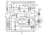
- FIG. 1 is a configuration diagram of an engine cooling system according to an embodiment of the present invention.
- FIG. 1 shows an engine cooling system according to an embodiment of the present invention.
- This engine cooling system includes a sub-radiator 2 and a radiator 3 arranged in order from the front of the vehicle 1.
- the sub-radiator 2 and the radiator 3 perform cooling by air cooling using vehicle speed air or cooling air from a cooling fan (not shown) when the vehicle 1 is traveling or idling.
- the air A sucked into the intake passage 5 becomes the intake air 6 and passes through an air cleaner (not shown) and is then compressed by the compressor 8 of the turbocharger 7 to be cooled by water. After being cooled by the intercooler 9 of the type, it is supplied to the engine body 11 through the intake manifold 10.
- Intercooler cooling water 12 used for cooling in the intercooler 9 is forcibly circulated between the sub radiator 2 and the water pump 13.
- the intake air 6 supplied to the engine body 11 is mixed with fuel and combusted to generate heat energy, and then becomes combustion gas 14 and is exhausted from the exhaust manifold 15 to the exhaust passage 16.
- the EGR gas 18 is diverted to the EGR passage 17 connected to the intake passage 5 on the downstream side of the intercooler 9.
- a water-cooled EGR cooler 19 and an EGR valve 20 that adjusts the flow rate of the EGR gas 18 are sequentially arranged from the exhaust passage 16 side.
- the engine main body cooling water 21 that cools the engine main body 11 and the EGR cooler cooling water 22 that is used for cooling by the EGR cooler 19 are controlled by the thermostat 23 while the flow rate is adjusted by the thermostat 23 and the water pump 13. Each is forced to circulate.
- the cooling water 24 diverted from the thermostat 23 when the engine body 11 is warmed up circulates without passing through the radiator 3.
- a part of the engine main body cooling water 21 is usually used for the EGR cooler cooling water 22.
- the combustion gas 14 that has not been split into the EGR passage 17 is rotated into the turbine 25 of the turbocharger 7, and then, after the harmful substances are purified by the exhaust gas purification device 26 made of DPF, SCR, etc., becomes the exhaust gas G into the atmosphere. Released into.
- the engine cooling system includes a Rankine cycle 32 in which a first refrigerant 31 is circulated in order through a refrigerant pump 27, a first evaporator 28, a first expander 29, and a first condenser 30, and the sub radiator 2 and It is provided in parallel with a conventional engine cooling system composed of the radiator 3.
- a part of the outlet side cooling water 34 (intercooler cooling water 12 after air cooling) of the sub radiator 2 is diverted from the vicinity of the inlet of the intercooler 9, and the first condensation After passing through the vessel 30, it becomes the cooling water 35 and merges with the cooling water 36 after passing through the first evaporator 28.
- the refrigerant 31 flowing through the Rankine cycle 32 is compressed in a liquid state by the refrigerant pump 27 and is heated at a constant pressure by a part of the inlet side cooling water 33 of the radiator 3 in the first evaporator 28 to become high-pressure superheated steam, After adiabatic expansion in the first expander 29, the first condenser 30 is cooled at a constant pressure by a part of the outlet side cooling water 34 of the sub radiator 2 and returns to the liquid again.
- the second refrigerant 40 circulates in turn through the second expander 37, the second evaporator 38, the compressor (compressor) 39, and the cooled side of the first condenser 30 of the Rankine cycle 32.
- the air conditioner cooling cycle 41 is provided.
- the gaseous second refrigerant 40 is compressed by a compressor 39 into a high-temperature and high-pressure semi-liquid, and is cooled by a part of the outlet side cooling water 34 of the sub-radiator 2 in the first condenser 30.
- the liquefaction is further liquefied and converted into a low-pressure low-temperature mist-like liquid by the second expander 37, and then the second evaporator 38 is vaporized again by heat exchange with air to generate cold air to cool the vehicle 1.
- the liquefaction of the second refrigerant 40 of the cooling cycle 41 for the air conditioner is not the air-cooled condenser for the air conditioner arranged on the front surface of the vehicle 1 as in the prior art, but the first evaporator 30 of the Rankine cycle 32.
- a part of the outlet side cooling water 34 that is air-cooled by the sub-radiator 2 is used, so that it is not necessary to provide the vehicle 1 with an air-cooled condenser, and the air-conditioner cooling cycle 41 is cooled by water. Therefore, the increase in the vehicle weight accompanying the mounting of the Rankine cycle 32 can be suppressed.
- the air-cooled condenser for the air conditioner is removed from the front surface of the vehicle 1, the ventilation resistance of the sub-radiator 2 and the radiator 3 is reduced, so that the cooling water 33 and 34 having a sufficient temperature difference in the Rankine cycle 32.
- the performance of Rankine cycle 32 can be improved.
- the cooling target of the engine cooling system of the present invention is not limited to the diesel engine 4 as described above, but also includes a gasoline engine.
Landscapes
- Engineering & Computer Science (AREA)
- Chemical & Material Sciences (AREA)
- Combustion & Propulsion (AREA)
- Mechanical Engineering (AREA)
- General Engineering & Computer Science (AREA)
- Physics & Mathematics (AREA)
- Thermal Sciences (AREA)
- Engine Equipment That Uses Special Cycles (AREA)
Abstract
Description
2 サブラジエータ
3 ラジエータ
4 ディーゼルエンジン
9 インタークーラ
11 エンジン本体
21 エンジン本体用冷却水
12 インタークーラ用冷却水
27 冷媒ポンプ
28 第1蒸発器
29 第1膨張器
30 第1凝縮器
31 第1冷媒
32 ランキンサイクル
33 (ラジエータの)入口側冷却水
34 (サブラジエータの)出口側冷却水
41 エアコン用冷却サイクル
Claims (3)
- 冷媒ポンプ、蒸発器、膨張器及び凝縮器を第1の冷媒が順に循環してなるランキンサイクルと、液体状の第2の冷媒の気化を利用して車両を冷房するエアコン用の冷却サイクルと、車両の前面に配置されたエンジン本体用の冷却水が流れるラジエータ、及びインタークーラ用の冷却水が流れるサブラジエータとを備え、
前記ラジエータの入口側の冷却水の一部を前記蒸発器の加熱源に、前記サブラジエータの出口側の冷却水の一部を前記凝縮器の冷却源に、それぞれ用いるエンジン冷却システムにおいて、
前記気化した第2の冷媒を、前記凝縮器における前記サブラジエータの出口側の冷却水の一部を用いて冷却することで再び液化させることを特徴とするエンジン冷却システム。 - 前記エアコン用の冷却サイクルが、第2膨張器、第2蒸発器、圧縮機及び前記凝縮器の被冷却側を前記第2の冷媒が順に循環してなる請求項1に記載のエンジン冷却システム。
- 前記蒸発器を通過した前記ラジエータの入口側の冷却水と、前記凝縮器を通過した前記サブラジエータの出口側の冷却水とを合流させた後に前記ラジエータへ供給する請求項1又は2に記載のエンジン冷却システム。
Priority Applications (3)
| Application Number | Priority Date | Filing Date | Title |
|---|---|---|---|
| CN201480047027.4A CN105473834A (zh) | 2013-10-30 | 2014-10-03 | 发动机冷却系统 |
| US15/022,835 US9745887B2 (en) | 2013-10-30 | 2014-10-03 | Engine cooling system |
| EP14856996.5A EP3064733B1 (en) | 2013-10-30 | 2014-10-03 | Engine cooling system |
Applications Claiming Priority (2)
| Application Number | Priority Date | Filing Date | Title |
|---|---|---|---|
| JP2013225544A JP2015086778A (ja) | 2013-10-30 | 2013-10-30 | エンジン冷却システム |
| JP2013-225544 | 2013-10-30 |
Publications (1)
| Publication Number | Publication Date |
|---|---|
| WO2015064301A1 true WO2015064301A1 (ja) | 2015-05-07 |
Family
ID=53003914
Family Applications (1)
| Application Number | Title | Priority Date | Filing Date |
|---|---|---|---|
| PCT/JP2014/076552 Ceased WO2015064301A1 (ja) | 2013-10-30 | 2014-10-03 | エンジン冷却システム |
Country Status (5)
| Country | Link |
|---|---|
| US (1) | US9745887B2 (ja) |
| EP (1) | EP3064733B1 (ja) |
| JP (1) | JP2015086778A (ja) |
| CN (1) | CN105473834A (ja) |
| WO (1) | WO2015064301A1 (ja) |
Cited By (1)
| Publication number | Priority date | Publication date | Assignee | Title |
|---|---|---|---|---|
| EP3009625A1 (de) * | 2014-10-18 | 2016-04-20 | MAN Truck & Bus AG | Kühlsystem für ein fahrzeug, insbesondere für ein nutzfahrzeug |
Families Citing this family (25)
| Publication number | Priority date | Publication date | Assignee | Title |
|---|---|---|---|---|
| JP6207941B2 (ja) * | 2013-09-12 | 2017-10-04 | サンデンホールディングス株式会社 | 排熱回収装置 |
| JP2015086779A (ja) * | 2013-10-30 | 2015-05-07 | いすゞ自動車株式会社 | エンジン冷却システム |
| US20170074123A1 (en) * | 2014-03-21 | 2017-03-16 | Dana Limited | Enhanced condenser for a waste heat recovery system |
| US10323548B2 (en) * | 2014-06-26 | 2019-06-18 | Volvo Truck Corporation | Internal combustion engine waste heat recovery (WHR) device including multiple cooling sources for a WHR condenser |
| KR101610150B1 (ko) | 2014-10-22 | 2016-04-08 | 현대자동차 주식회사 | 냉각 시스템 및 이를 제어하는 방법 |
| US20160265393A1 (en) * | 2015-03-10 | 2016-09-15 | Denso International America, Inc. | Regenerative Rankine Cycle For Vehicles |
| JP6593056B2 (ja) * | 2015-09-17 | 2019-10-23 | いすゞ自動車株式会社 | 熱エネルギー回収システム |
| JP6641865B2 (ja) * | 2015-10-08 | 2020-02-05 | いすゞ自動車株式会社 | 車両用冷却装置 |
| US10240514B2 (en) | 2015-11-03 | 2019-03-26 | Hyundai Motor Company | Water-cooled intercooler system using air conditioning system and control method thereof |
| JP6604540B2 (ja) * | 2015-11-24 | 2019-11-13 | いすゞ自動車株式会社 | エンジン冷却装置 |
| JP6539192B2 (ja) * | 2015-12-03 | 2019-07-03 | マツダ株式会社 | エンジンの制御装置 |
| SE541556C2 (en) * | 2016-01-15 | 2019-10-29 | Scania Cv Ab | A cooling system for a combustion engine and a WHR system |
| KR102604087B1 (ko) | 2016-06-24 | 2023-11-21 | 삼성디스플레이 주식회사 | 윈도우 및 이를 포함하는 표시 장치 |
| CN106351740A (zh) * | 2016-08-31 | 2017-01-25 | 泰豪科技股份有限公司 | 含有蒸发器的发动机水冷系统 |
| CN106762088B (zh) * | 2016-11-16 | 2019-05-17 | 浙江吉利控股集团有限公司 | 一种用于电池和中冷器冷却的车用冷却系统及其方法 |
| CN106481434B (zh) * | 2016-12-05 | 2019-03-05 | 湖北鹰牌动力科技有限公司 | 一种发动机的余热利用装置 |
| CN106523184B (zh) * | 2016-12-05 | 2017-12-26 | 湖北鹰牌动力科技有限公司 | 一种发动机的余热利用系统 |
| KR102335331B1 (ko) * | 2017-04-18 | 2021-12-03 | 현대자동차 주식회사 | 연료 개질 시스템 및 냉각수 공급 제어 방법 |
| KR102322256B1 (ko) * | 2017-05-08 | 2021-11-04 | 현대자동차 주식회사 | 연료 개질 시스템 |
| EP3404244B1 (de) * | 2017-05-15 | 2021-02-24 | Orcan Energy AG | Vorrichtung und verfahren zur standardisierung und zum aufbau eines orc-containers |
| US10550758B2 (en) | 2017-12-18 | 2020-02-04 | Cnh Industrial America Llc | Cooling system for a work vehicle |
| US10352229B2 (en) | 2017-12-18 | 2019-07-16 | Cnh Industrial America Llc | Cooling system for a work vehicle |
| WO2021044177A1 (ja) * | 2019-09-02 | 2021-03-11 | 日産自動車株式会社 | 車両の熱交換装置 |
| CN110985230B (zh) * | 2019-12-16 | 2021-03-16 | 西安交通大学 | 一种汽车废热回收利用系统及其操作方法 |
| AT524156B1 (de) * | 2020-08-04 | 2022-07-15 | Man Truck & Bus Se | Vorrichtung zur Energierückgewinnung mit einem Abwärmenutzungskreislauf |
Citations (4)
| Publication number | Priority date | Publication date | Assignee | Title |
|---|---|---|---|---|
| JPS5888409A (ja) * | 1981-11-20 | 1983-05-26 | Komatsu Ltd | デイ−ゼルエンジンのランキンボトミング装置 |
| JPH1151582A (ja) | 1997-07-28 | 1999-02-26 | Isuzu Ceramics Kenkyusho:Kk | ランキンサイクルにおけるコンデンサ |
| JP2005186879A (ja) * | 2003-12-26 | 2005-07-14 | Calsonic Kansei Corp | 車両用熱交換器システム |
| JP2010064527A (ja) * | 2008-09-08 | 2010-03-25 | Denso Corp | 車両用冷却システム |
Family Cites Families (11)
| Publication number | Priority date | Publication date | Assignee | Title |
|---|---|---|---|---|
| US6962056B2 (en) * | 2002-11-13 | 2005-11-08 | Carrier Corporation | Combined rankine and vapor compression cycles |
| CN1940254B (zh) * | 2005-09-29 | 2014-04-16 | 罗桂荣 | 动力循环系统与制冷循环系统复合式热力发动机 |
| US7690213B2 (en) * | 2006-02-24 | 2010-04-06 | Denso Corporation | Waste heat utilization device and control method thereof |
| US20080041046A1 (en) * | 2006-08-16 | 2008-02-21 | Deere & Company, A Delaware Corporation | Engine waste heat recovery system |
| US20080087017A1 (en) * | 2006-10-16 | 2008-04-17 | Van Nimwegen Robert R | Van Nimwegen efficient pollution free internal combustion engine |
| AT507096B1 (de) * | 2008-12-10 | 2010-02-15 | Man Nutzfahrzeuge Oesterreich | Antriebseinheit mit kühlkreislauf und separatem wärmerückgewinnungskreislauf |
| CN101566113B (zh) * | 2009-06-03 | 2011-06-08 | 浙江银轮机械股份有限公司 | 基于有机朗肯循环的发动机废热回收系统 |
| SE535877C2 (sv) * | 2010-05-25 | 2013-01-29 | Scania Cv Ab | Kylarrangemang hos ett fordon som drivs av en överladdad förbränningsmotor |
| JP5894756B2 (ja) * | 2011-09-30 | 2016-03-30 | 日産自動車株式会社 | ランキンサイクルシステム |
| JP2013076374A (ja) * | 2011-09-30 | 2013-04-25 | Nissan Motor Co Ltd | ランキンサイクル及びランキンサイクルに用いる熱交換器 |
| US9316141B2 (en) * | 2013-02-15 | 2016-04-19 | Enis Pilavdzic | Engine energy management system |
-
2013
- 2013-10-30 JP JP2013225544A patent/JP2015086778A/ja active Pending
-
2014
- 2014-10-03 US US15/022,835 patent/US9745887B2/en active Active
- 2014-10-03 CN CN201480047027.4A patent/CN105473834A/zh active Pending
- 2014-10-03 WO PCT/JP2014/076552 patent/WO2015064301A1/ja not_active Ceased
- 2014-10-03 EP EP14856996.5A patent/EP3064733B1/en not_active Not-in-force
Patent Citations (4)
| Publication number | Priority date | Publication date | Assignee | Title |
|---|---|---|---|---|
| JPS5888409A (ja) * | 1981-11-20 | 1983-05-26 | Komatsu Ltd | デイ−ゼルエンジンのランキンボトミング装置 |
| JPH1151582A (ja) | 1997-07-28 | 1999-02-26 | Isuzu Ceramics Kenkyusho:Kk | ランキンサイクルにおけるコンデンサ |
| JP2005186879A (ja) * | 2003-12-26 | 2005-07-14 | Calsonic Kansei Corp | 車両用熱交換器システム |
| JP2010064527A (ja) * | 2008-09-08 | 2010-03-25 | Denso Corp | 車両用冷却システム |
Cited By (1)
| Publication number | Priority date | Publication date | Assignee | Title |
|---|---|---|---|---|
| EP3009625A1 (de) * | 2014-10-18 | 2016-04-20 | MAN Truck & Bus AG | Kühlsystem für ein fahrzeug, insbesondere für ein nutzfahrzeug |
Also Published As
| Publication number | Publication date |
|---|---|
| US20160230641A1 (en) | 2016-08-11 |
| EP3064733B1 (en) | 2018-08-29 |
| CN105473834A (zh) | 2016-04-06 |
| EP3064733A4 (en) | 2017-08-09 |
| JP2015086778A (ja) | 2015-05-07 |
| US9745887B2 (en) | 2017-08-29 |
| EP3064733A1 (en) | 2016-09-07 |
Similar Documents
| Publication | Publication Date | Title |
|---|---|---|
| WO2015064301A1 (ja) | エンジン冷却システム | |
| EP3064734B1 (en) | Engine cooling system | |
| US20150377180A1 (en) | System for recuperating heat from the exhaust gases in an internal combustion engine, with two heat exchangers on a gas recirculation circuit | |
| JP2013238131A (ja) | 廃熱利用装置 | |
| CN103038475B (zh) | 用于发动机排放气体再循环回路的冷却装置 | |
| JP5475924B2 (ja) | 内燃機関へ送られる圧縮空気および/または再循環排気ガスを冷却する装置 | |
| WO2013151079A1 (ja) | ランキンサイクル装置 | |
| JP6197459B2 (ja) | エンジン冷却システム | |
| JP6186866B2 (ja) | エンジンの冷却システム | |
| WO2016002711A1 (ja) | 廃熱回生システム | |
| WO2014103977A1 (ja) | 内燃機関の廃熱利用装置 | |
| JP2007255278A (ja) | エンジンのランキンサイクルシステム | |
| JP2017120067A (ja) | 車両用冷却システムの制御装置 | |
| JP2013160076A (ja) | ランキンサイクル装置 | |
| RU168451U1 (ru) | Система питания воздухом комбинированного двигателя с глубоким охлаждением | |
| JP2013068137A (ja) | 廃熱利用装置 | |
| CN108026791B (zh) | 热能回收系统 | |
| JP6186867B2 (ja) | エンジンの冷却システム | |
| JP2013217222A (ja) | ランキンサイクル装置 | |
| JP2019027332A (ja) | 車両の廃熱回収装置。 | |
| JP2017101566A (ja) | 車両用冷却装置 | |
| JP2017120068A (ja) | 廃熱回収装置 | |
| JP2015151880A (ja) | エンジン冷却システム | |
| GB2533648A (en) | The ultimate thermodynamically efficient eco-boost, or exhaust eco-throttled engine | |
| JP2013072295A (ja) | 廃熱利用装置 |
Legal Events
| Date | Code | Title | Description |
|---|---|---|---|
| WWE | Wipo information: entry into national phase |
Ref document number: 201480047027.4 Country of ref document: CN |
|
| 121 | Ep: the epo has been informed by wipo that ep was designated in this application |
Ref document number: 14856996 Country of ref document: EP Kind code of ref document: A1 |
|
| WWE | Wipo information: entry into national phase |
Ref document number: 15022835 Country of ref document: US |
|
| REEP | Request for entry into the european phase |
Ref document number: 2014856996 Country of ref document: EP |
|
| WWE | Wipo information: entry into national phase |
Ref document number: 2014856996 Country of ref document: EP |
|
| NENP | Non-entry into the national phase |
Ref country code: DE |