WO2015064332A1 - レーザ加工機 - Google Patents
レーザ加工機 Download PDFInfo
- Publication number
- WO2015064332A1 WO2015064332A1 PCT/JP2014/077057 JP2014077057W WO2015064332A1 WO 2015064332 A1 WO2015064332 A1 WO 2015064332A1 JP 2014077057 W JP2014077057 W JP 2014077057W WO 2015064332 A1 WO2015064332 A1 WO 2015064332A1
- Authority
- WO
- WIPO (PCT)
- Prior art keywords
- cover
- laser processing
- processing machine
- processing
- workpiece
- Prior art date
- Legal status (The legal status is an assumption and is not a legal conclusion. Google has not performed a legal analysis and makes no representation as to the accuracy of the status listed.)
- Ceased
Links
Images








Classifications
-
- B—PERFORMING OPERATIONS; TRANSPORTING
- B23—MACHINE TOOLS; METAL-WORKING NOT OTHERWISE PROVIDED FOR
- B23K—SOLDERING OR UNSOLDERING; WELDING; CLADDING OR PLATING BY SOLDERING OR WELDING; CUTTING BY APPLYING HEAT LOCALLY, e.g. FLAME CUTTING; WORKING BY LASER BEAM
- B23K26/00—Working by laser beam, e.g. welding, cutting or boring
-
- B—PERFORMING OPERATIONS; TRANSPORTING
- B23—MACHINE TOOLS; METAL-WORKING NOT OTHERWISE PROVIDED FOR
- B23K—SOLDERING OR UNSOLDERING; WELDING; CLADDING OR PLATING BY SOLDERING OR WELDING; CUTTING BY APPLYING HEAT LOCALLY, e.g. FLAME CUTTING; WORKING BY LASER BEAM
- B23K26/00—Working by laser beam, e.g. welding, cutting or boring
- B23K26/02—Positioning or observing the workpiece, e.g. with respect to the point of impact; Aligning, aiming or focusing the laser beam
-
- B—PERFORMING OPERATIONS; TRANSPORTING
- B23—MACHINE TOOLS; METAL-WORKING NOT OTHERWISE PROVIDED FOR
- B23K—SOLDERING OR UNSOLDERING; WELDING; CLADDING OR PLATING BY SOLDERING OR WELDING; CUTTING BY APPLYING HEAT LOCALLY, e.g. FLAME CUTTING; WORKING BY LASER BEAM
- B23K26/00—Working by laser beam, e.g. welding, cutting or boring
- B23K26/08—Devices involving relative movement between laser beam and workpiece
-
- B—PERFORMING OPERATIONS; TRANSPORTING
- B23—MACHINE TOOLS; METAL-WORKING NOT OTHERWISE PROVIDED FOR
- B23K—SOLDERING OR UNSOLDERING; WELDING; CLADDING OR PLATING BY SOLDERING OR WELDING; CUTTING BY APPLYING HEAT LOCALLY, e.g. FLAME CUTTING; WORKING BY LASER BEAM
- B23K26/00—Working by laser beam, e.g. welding, cutting or boring
- B23K26/36—Removing material
- B23K26/38—Removing material by boring or cutting
-
- B—PERFORMING OPERATIONS; TRANSPORTING
- B23—MACHINE TOOLS; METAL-WORKING NOT OTHERWISE PROVIDED FOR
- B23K—SOLDERING OR UNSOLDERING; WELDING; CLADDING OR PLATING BY SOLDERING OR WELDING; CUTTING BY APPLYING HEAT LOCALLY, e.g. FLAME CUTTING; WORKING BY LASER BEAM
- B23K26/00—Working by laser beam, e.g. welding, cutting or boring
- B23K26/70—Auxiliary operations or equipment
- B23K26/702—Auxiliary equipment
- B23K26/706—Protective screens
-
- B—PERFORMING OPERATIONS; TRANSPORTING
- B23—MACHINE TOOLS; METAL-WORKING NOT OTHERWISE PROVIDED FOR
- B23K—SOLDERING OR UNSOLDERING; WELDING; CLADDING OR PLATING BY SOLDERING OR WELDING; CUTTING BY APPLYING HEAT LOCALLY, e.g. FLAME CUTTING; WORKING BY LASER BEAM
- B23K37/00—Auxiliary devices or processes, not specially adapted for a procedure covered by only one of the other main groups of this subclass
- B23K37/02—Carriages for supporting the welding or cutting element
- B23K37/0211—Carriages for supporting the welding or cutting element travelling on a guide member, e.g. rail, track
- B23K37/0235—Carriages for supporting the welding or cutting element travelling on a guide member, e.g. rail, track the guide member forming part of a portal
-
- B—PERFORMING OPERATIONS; TRANSPORTING
- B23—MACHINE TOOLS; METAL-WORKING NOT OTHERWISE PROVIDED FOR
- B23K—SOLDERING OR UNSOLDERING; WELDING; CLADDING OR PLATING BY SOLDERING OR WELDING; CUTTING BY APPLYING HEAT LOCALLY, e.g. FLAME CUTTING; WORKING BY LASER BEAM
- B23K37/00—Auxiliary devices or processes, not specially adapted for a procedure covered by only one of the other main groups of this subclass
- B23K37/04—Auxiliary devices or processes, not specially adapted for a procedure covered by only one of the other main groups of this subclass for holding or positioning work
- B23K37/0408—Auxiliary devices or processes, not specially adapted for a procedure covered by only one of the other main groups of this subclass for holding or positioning work for planar work
-
- B—PERFORMING OPERATIONS; TRANSPORTING
- B23—MACHINE TOOLS; METAL-WORKING NOT OTHERWISE PROVIDED FOR
- B23K—SOLDERING OR UNSOLDERING; WELDING; CLADDING OR PLATING BY SOLDERING OR WELDING; CUTTING BY APPLYING HEAT LOCALLY, e.g. FLAME CUTTING; WORKING BY LASER BEAM
- B23K2101/00—Articles made by soldering, welding or cutting
- B23K2101/18—Sheet panels
Definitions
- the present invention includes a single-function processing machine that performs only laser processing [laser processing] and a combined processing machine that performs both laser processing and turret punch press processing [combined processing processing machine] Relates to a laser processing machine including:
- Patent Document 1 discloses a laser processing machine that covers the upper surface of a processing table on which a workpiece is placed and is provided with a cover that can move along the moving direction of the workpiece.
- a cover that covers the entire processing machine If a cover that covers the entire processing machine is provided, the size of the device increases. In particular, in a processing machine in which the processing table is movable, it is necessary to enclose the entire moving range of the table with a cover, so that the size of the cover increases, and the cost increases accordingly. In addition, since the cover covers the entire processing machine, workability for loading and unloading workpieces also deteriorates.
- the size of the cover can be made smaller than the size of the cover covering the entire processing machine.
- the area covering the processing table is determined by the size of the cover, there is a limit to cover only a necessary range without impeding workability for loading and unloading the workpiece with a compact cover.
- the present invention is to provide a laser processing machine capable of covering only a necessary range at the time of laser processing with a compact cover without impeding workability of loading and unloading of a workpiece.
- a feature of the present invention is a laser processing machine, a processing machine body having a laser processing head, A processing table on which a workpiece to be processed is placed and a light-shielding cover that is provided above the processing table and covers the upper surface of the processing table are provided.
- the cover can be deformed into an expanded state and a stored state.
- a laser processing machine capable of adjusting an area covering the upper surface of the processing table is provided.
- the cover can be made compact while maintaining the light shielding property of the laser beam during laser processing, the sound insulation property of the sound generated during processing, and the dust resistance such as spatter and dust generated during processing. Compared to a full cover or a cover with a certain size). As a result, it is possible to reduce the weight and cost of the cover. In addition, since the cover can be opened within a range necessary for carrying in or carrying out the workpiece when carrying in or carrying out the workpiece W, it is possible to easily carry in or carry out the workpiece.
- the position where the cover covers the processing table can be changed.
- the cover is a telescopic cover that can be deformed into the expanded state and the retracted state by combining a plurality of divided covers having different sizes in order to be slidable.
- the telescopic cover can be configured with a simple structure, and the cover can be easily operated.
- the cover is provided with a window with a light shielding filter.
- a clearance is formed between the lower edge of the cover and the processing table, and a lifting shutter that shields the clearance in a state of protruding upward is provided on the processing table. It is preferable to be provided so as to protrude from the upper surface.
- the laser processing machine further includes a sensor that is provided above the processing table and detects contact with the workpiece moving on the processing table.
- the laser processing machine can be stopped when the sensor comes into contact with a [curled-up or jammed] workpiece that has been warped or caught. Therefore, it is possible to reliably prevent damage to the cover and the carriage that holds the workpiece.
- the laser processing machine further includes a carriage that holds the workpiece and is movable inside the cover, and a turret that performs turret punch press processing on the workpiece while moving the carriage. .
- punch press processing can be performed without the cover interfering with punch press processing.
- (A) is a perspective view (cover unfolded state) of 1st Embodiment (combined processing machine) of a laser beam machine
- (b) is a perspective view (cover accommodation state) of the said laser beam machine. It is a schematic plan view (left-right cover expansion
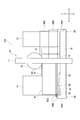
- FIG. 2 is a schematic plan view of the laser beam machine (left and right cover unfolded state: workpiece loading state).
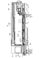
- (A) is sectional drawing of the cover of an unfolded state
- (b) is sectional drawing of the cover of an accommodation state.
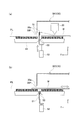
- (A) is sectional drawing which shows the raising / lowering shutter for light-shielding
- (b) is sectional drawing which shows the raising / lowering shutter for light-shielding processed.
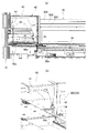
- (A) is an expanded sectional view which shows the sensor which detects the contact of a cover and a workpiece
- (b) is an enlarged perspective view which shows the said sensor. It is side sectional drawing of the said laser beam machine.
- (A) is a perspective view (cover accommodation state) of 2nd Embodiment (single function processing machine) of a laser beam machine
- (b) is a perspective view (cover expansion
- It is a perspective view of 3rd Embodiment of a laser beam machine.
- the laser processing machine M1 of the first embodiment is a punch-pressing / laser-processing combined machine in which a turret punch press processing apparatus and a laser processing apparatus are combined.
- the laser processing machine M1 includes a processing machine body [machine ⁇ main body] 10 and a processing table on which a workpiece to be processed is placed (a fixed table 14 or A movable table 15 and the like, and a light-shielding cover (also referred to as a movable cover 30 and a fixed cover 40, which will be described later, and a cabin) covering the processing table.
- the processing machine body 10 includes a laser processing head 20 and a turret 12 for punch press processing (see FIG. 2).
- the workpiece W (see FIGS. 3 and 4) placed on the processing table is irradiated with laser light from the laser processing head 20, and the workpiece W is laser processed.
- punch pressing the workpiece is punch pressed by the tool [tool] (punch and die) mounted on the turret 12 while moving the carriages 18 and 19 (see FIG. 2) holding the workpiece W. Is done.
- the turret 12 and the laser processing head 20 are located approximately at the center in the X-axis direction of the laser processing machine M1.
- the processing machine main body 10 provided with is arranged, and a fixed table 13 is arranged below the processing machine main body 10.
- a moving table 15 and a fixed table 14 are sequentially arranged on one side (left side in FIG. 2) of the processing machine body 10 in the X-axis direction.
- a moving table 16 and a fixed table 17 are also arranged in this order on the other side of the processing machine body 10 (the right side in FIG. 2).
- the processing machine body 10 has a gate-shaped frame 11, and a turret 12 is rotatably provided on the frame 11.
- the turret 12 has an upper turret to which a punch is attached and a lower turret to which a die is attached.
- the turret 12 is configured so that a mounted tool can be indexed at a processing position during punching.
- the frame 11 is provided with the above-described fixed table 13 that supports the plate-like workpiece W.
- the above-described moving tables 15 and 16 are provided so as to be movable in the Y-axis direction.
- the above-described fixed tables 14 and 17 are provided outside the moving tables 15 and 16, respectively.
- the fixed tables 13, 14 and 17 and the moving tables 15 and 16 constitute a processing table. When the fixed table and the moving table are not distinguished, they are simply referred to as a processing table.
- each of the moving tables 15 and 16 is connected to a Y-axis carriage 18 that extends in the X-axis direction and is movable in the Y-axis direction.
- the Y-axis carriage 18 and the moving tables 15 and 16 can be moved in the Y-axis direction and positioned at desired positions.
- the Y-axis carriage 18 is provided with an X-axis carriage 19 that can move in the X-axis direction.
- the X-axis carriage 19 is equipped with a clamp device 25 that holds the edge of the workpiece W. Therefore, the clamp device 25 can be moved in the X-axis direction on the Y-axis carriage 18 positioned at a desired position along the Y-axis direction and positioned at the desired position.
- the clamp device 25 is disposed so as to clamp a side edge (a lower side edge in FIG. 2) extending in the X-axis direction of the rectangular plate-shaped workpiece W.
- a Y-axis sub-carriage 21 is provided above the moving table 15 on one side of the processing machine body 10.
- the laser processing head 20 is attached to a Y-axis subcarriage 21 and is movable along the Y-axis subcarriage 21 in the Y-axis direction.
- the laser processing head 20 can also move in the Z-axis direction orthogonal to the X-axis direction and the Y-axis direction. 2 and 4, the laser processing head 20 is shown at the movement limit position on the Y-axis subcarriage 21, respectively.
- the workpiece W When performing punch press processing with the laser processing machine M1, the workpiece W is moved to the processing position by the Y-axis carriage 18 and the X-axis carriage 19, and is positioned at the processing position. In other words, the workpiece W is carried onto the processing table, and after positioning the origin, the side edge described above is clamped by the clamp device 25. The workpiece W clamped by the clamping device 25 is moved to the machining position by the Y-axis carriage 18 and the X-axis carriage 19 and positioned at the machining position. The workpiece W positioned at the processing position is punch press processed.
- the Y-axis sub-carriage is fixed with the Y-axis carriage 18 fixed at the origin position. 21 and the X-axis carriage 19 are moved to perform laser processing.
- the cover covers the laser processing range and protects the inside so that the laser beam does not leak to the outside.
- the covers have a size that allows the carriages 18, 19 and 21 to move therein.
- the movable cover 30 and the fixed cover 40 are respectively provided on the processing tables (the fixed tables 14 and 17 and the moving tables 15 and 16) on both sides of the processing machine body 10. Note that the fixed cover 40 is not shown in FIG. In FIG. 1, only the left movable cover 30 and the fixed cover 40 in FIG. 2 are visible, and the right movable cover 30 and the fixed cover 40 are hidden behind the processing machine body 10.
- the fixed cover 40 is fixed to the side portion of the processing machine body 10.
- a guide rail 38 extending in the Y-axis direction is provided on the side surface of the fixed cover 40.
- inclined end covers 42 that can be opened upward when necessary are provided at both ends (or only one of both ends) of the fixed cover 40 in the Y-axis direction.
- the end cover 42 is provided with a window 44 for visually recognizing the inside. Note that the end cover 42 may not be inclined and may not be openable.
- the movable cover 30 is configured to be changeable between a deployed state [deployed state] shown in FIG. 1 (a) and a retracted state (retracted state) shown in FIG. 1 (b). Therefore, the movable cover 30 can adjust the area (width) covering the processing table (mainly the fixed table 14).
- the movable cover 30 is movable in the Y-axis direction, and the position covering the processing table (mainly the fixed table 14) can also be changed.
- the movable cover 30 is configured by combining divided covers 30A, 30B, and 30C having different sizes in order to be slidable in the Y-axis direction. That is, the movable cover 30 can be transformed into a deployed state in which the divided covers 30A, 30B, and 30C do not overlap each other and a storage state in which the divided covers 30A, 30B, and 30C are stacked on each other [transformable]. It is a cover.
- the division covers 30A, 30B, and 30C may be developed and stored manually, or automatically by an air cylinder or an electric cylinder.
- the engaging portions 39 and 37 of the divided covers 30A, 30B, and 30C are engaged with the guide rail 38 provided on the side surface of the fixed cover 40 and the guide rail 36 provided on the side edge of the fixed table 14, respectively.
- the divided covers 30A, 30B, and 30C are slidable in the Y-axis direction.
- the divided covers 30 ⁇ / b> A, 30 ⁇ / b> B, and 30 ⁇ / b> C each have a horizontal plate part 31 that is parallel to the upper surface of the fixed table 14 and a slanted plate part 32 that is inclined downward from one edge of the horizontal plate part 31. And a vertical plate portion (vertical plate) 33 suspended from the edge of the inclined plate portion 32.
- the above-described engaging portion 39 that is slidably engaged with the guide rail 38 is provided at the other edge portion of the horizontal plate portion 31, and the above-mentioned engaging portion slidably engages with the guide rail 36 on the inner surface of the lower end of the vertical plate portion 33.
- the engaging portion 37 is provided.
- Each of the inclined plate portions 32 of the divided covers 30A, 30B, and 30C is provided with a window 34 with a light shielding filter for visually confirming the inside.
- the window 34 is arrange
- the front edge of the divided cover 30A is provided with a flange 30As that engages with the flange 30Bt on the rear edge of the next divided cover 30B.
- a flange 30Bs that engages with a flange 30Ct at the rear edge of the next divided cover 30C is provided at the front edge of the divided cover 30B.
- the elevating shutter 51 is provided so as to protrude from the upper surface of the fixed table 14. By projecting the lift shutter 51 upward, the gap 30P is closed, and the laser beam is prevented from leaking outside through the gap 30P.
- the lift shutter 51 is accommodated in the slit 50 provided in the fixed table 14 as shown in FIG. 6 (b) when not in use, and when necessary, as shown in FIG. 6 (a). It is raised by an elevating mechanism 52 such as a cylinder.
- the gap 30P can be shielded by such a mechanism.
- a bracket 55 is fixed in the vicinity of the end cover 42 of the fixed cover 40, and a sensor 56 is attached to the bracket 55. Yes.
- the sensor 56 detects contact between the lower edge 30a of the front end of the divided cover 30C and the workpiece W moved in the Y-axis direction on the fixed table 14.
- the sensor 56 of this embodiment is a contact sensor, and the tip of the contact 56a protrudes downward from the lower edge 30a of the split cover 30C and the lower edge 42a of the end cover 42 and can be visually recognized from the outside.
- the sensor 56 makes laser processing when the contact W of the sensor 56a is brought into contact with the workpiece W before the warped or caught workpiece W comes into contact with the lower edge 30a or the like of the divided cover 30C, and the contact with the workpiece W is detected.
- the machine M1 is stopped.
- the sensor 56 may be fixed at a position other than the fixed cover 40 as long as it is arranged above the processing table.
- the movable cover 30 is stored (fully closed) and the Y-axis carriage 18 is moved forward to clamp the workpiece.
- the work W can be carried in or out using the device 25.
- the workpiece W is moved in the X-axis direction by the X-axis carriage 19 and the laser processing head 20 is moved in the Y-axis direction along the Y-axis sub-carriage 21 to thereby move in the XY plane.
- Laser processing is carried out. Since the workpiece W is moved only in the X-axis direction during laser processing, the movement range of the workpiece W is covered with the movable cover 30 and the laser beam is shielded.
- the elevating shutter 51 is raised to shield the gap 30P described above.
- punch press processing is performed by moving the workpiece W in the X-axis direction by the X-axis carriage 19 and moving the workpiece W in the Y-axis direction by the Y-axis carriage 18. Since the workpiece W is moved in the X-axis direction and the Y-axis direction during the punch press processing, as shown in FIG. 6B, the elevating shutter 51 is lowered and the above-described gap 30P is opened, and the workpiece W is opened. Can pass through the gap 30P.
- the area covering the upper surface of the processing table can be adjusted by the light-shielding movable cover 30 that covers the upper surface of the processing table (fixed tables 14 and 17). That is, by adjusting the size of the movable cover 30, only the laser processing range can be covered with the movable cover 30. Therefore, the movable cover 30 can be made compact while maintaining the light shielding property of the laser beam, the sound insulation property of the sound generated during the processing, and the dustproof property such as spatter and dust generated during the processing (the full cover covering the entire surface of the processing table). Compared to a cover or a cover with a certain size). As a result, the movable cover 30 can be reduced in weight and cost.
- the movable cover 30 can be opened within a range necessary for the work W to be carried in or out, so that the work W can be carried in or out. Can be easily performed.
- the position of the movable cover 30 can be changed, so that only the range necessary for laser processing can be efficiently protected.
- the movable cover 30 is configured as a telescopic cover, it can be configured with a simple structure and can be easily operated.
- the movable cover 30 can be deformed into a developed state and a stored state, and the area covering the upper surface of the processing table can be easily adjusted.
- the movable cover 30 is provided with a window 34 with a light shielding filter, the inside of the movable cover 30 can be visually confirmed during laser processing.
- the elevating shutter 51 by raising the elevating shutter 51, it is possible to prevent the laser light from leaking from the gap 30P between the lower edge 30a of the movable cover 30 and the processing table.
- the lifting shutter 51 by lowering the lifting shutter 51, the workpiece W can be moved while the movable table 30 covers the processing table.
- the raising / lowering shutter 51 does not contact the workpiece
- work W there is little consumption and it is excellent in durability.
- the gap was closed with a flexible sheet (see Patent Document 1 above), but the flexible sheet is inferior in durability because it comes into contact with the workpiece.
- the carriages 18 and 19 that hold the workpiece W can be freely moved in the movable cover 30 during the turret punch press processing.
- the movable cover 30 provided for laser processing does not get in the way during punch press processing.
- the sound produced at the time of punch press processing can be insulated by the movable cover 30.
- the punch / laser combined machine M1 can be stopped before the workpiece W comes into contact with the lower edge 30a of the divided cover 30C. Damage to the movable cover 30 and the Y-axis carriage 18 can be reliably prevented.
- the laser processing machine M2 is a single-function processing machine that performs only laser processing.
- the laser processing machine M2 includes a processing machine main body 60, a processing table 64 on which a workpiece to be processed is placed, and a light-shielding cover (movable cover 80) that covers the processing table 64.
- the processing machine body 60 is provided with a carriage (not shown) that can move in the Y-axis direction and a laser processing head (not shown) that can move in the X-axis direction orthogonal to the Y-axis direction in a horizontal plane. .
- the processing table 64 is provided along the Y-axis direction. The workpiece placed on the processing table 64 is irradiated with laser light, and the workpiece is laser processed.
- the movable cover 80 disposed above the processing table 64 is configured to be changeable between a storage state shown in FIG. 9A and an unfolded state shown in FIG. 9B. Therefore, the movable cover 80 can adjust the area covering the processing table 64. Further, the movable cover 80 is movable in the Y-axis direction, and the position covering the processing table 64 can also be changed.
- the movable cover 80 is configured by combining a plurality of divided covers 80A, 80B, 80C and 80D having different sizes in order to be slidable in the Y-axis direction. That is, the movable cover 80 can be deformed into an unfolded state where the divided covers 80A, 80B, 80C and 80D do not overlap each other, and the movable cover 80 can be deformed into a stored state where the divided covers 80A, 80B, 80C and 80D are overlapped with each other. This is a telescopic cover.
- the divided covers 80A, 80B, 80C, and 80D are arranged along the slide rail 66 so as to be slidable in the Y-axis direction.
- the division covers 80A, 80B, 80C, and 80D may be developed and stored manually, or automatically by an air cylinder or an electric cylinder. 9B, the gap between the lower edge of the split cover 80D and the processing table 64 is opened and closed by a lifting shutter 81.
- the area covering the upper surface of the processing table 64 can be adjusted by the light-shielding movable cover 80 that covers the upper surface of the processing table 64. That is, by adjusting the size of the movable cover 80, only the laser processing range can be covered with the movable cover 80. Therefore, the movable cover 80 can be made compact while maintaining the light shielding property of the laser beam, the sound insulation property of the sound generated during the processing, and the dustproof property such as spatter and dust generated during the processing (the full cover covering the entire surface of the processing table). Compared to a cover or a cover with a certain size). As a result, the movable cover 80 can be reduced in weight and cost.
- the movable cover 80 can be opened within a range necessary for the work W to be carried in or out, so that the work W can be carried in or out easily.
- the position of the movable cover 80 can be changed, so that only the range necessary for laser processing can be efficiently protected.
- the movable cover 80 is configured as a telescopic cover, it can be configured with a simple structure and can be easily operated.
- the movable cover 80 can be changed between a developed state and a stored state, and the area covering the upper surface of the processing table 64 can be easily adjusted.
- FIGS. 10 to 13 will be described.
- a cover (movable cover 130) that is slidable in the Y-axis direction is provided.
- the unfolded movable cover 130 covers the entire range of the upper surface of the processing table.
- Reference numeral 131 denotes a position in the storage state.
- a cover (movable cover 140) that is slidable in the X-axis direction is provided.
- the unfolded movable cover 140 covers the entire range of the upper surface of the processing table.
- Reference numeral 141 indicates a position in the storage state.
- a cover (movable cover 150) that can be deployed in the X-axis direction and can be stored is provided.
- the movable cover 150 in the stored state is stored below the processing table 14.
- Reference numeral 151 indicates a position in the storage state.
- a cover (movable cover 160) that can be deployed in the X-axis direction and can be stored is provided.
- Reference numeral 161 denotes a position in the storage state.
Landscapes
- Engineering & Computer Science (AREA)
- Physics & Mathematics (AREA)
- Optics & Photonics (AREA)
- Mechanical Engineering (AREA)
- Plasma & Fusion (AREA)
- Laser Beam Processing (AREA)
- Punching Or Piercing (AREA)
Abstract
レーザ加工機(M1)は、レーザ加工ヘッド(20)を有する加工機本体(10)と、加工すべきワーク(W)を載せる加工テーブル(14-15)と、前記加工テーブルの上方に設けられ、前記加工テーブルの上面を覆う遮光性のカバー(30,40)とを備えている。前記カバーは、展開状態と収納状態とに変形可能で、前記加工テーブルの上面を覆う面積を調整可能である。上記レーザ加工機によれば、ワークの搬入出の作業性を阻害せずに、コンパクトなカバーによって、レーザ加工時に必要な範囲だけを覆うことができる。
Description
本発明は、レーザ加工[laser processing]だけを行う単機能加工機[single-function processing machine]やレーザ加工とタレットパンチプレス加工[turret punch pressing]の両方を行う複合加工機[combined processing machine]などを含むレーザ加工機[laser processing machine]に関する。
板状ワークにレーザ光を照射して、当該ワークをレーザ加工するレーザ加工機では、目の保護や防塵などのために加工部位をカバーで覆うことが望ましい。加工機全体を覆うようにカバーが設けられた加工機が従来から知られている。また、下記特許文献1は、ワークが載せられる加工テーブルの上面を覆い、ワークの移動方向に沿って移動可能なカバーが設けられたレーザ加工機を開示している。
加工機全体を覆うカバーを設けると、装置の大きさが大きくなる。特に、加工テーブルが移動可能な加工機では、テーブルの移動範囲全体をカバーで囲う必要があるので、カバーの大きさが大きくなり、その分コスト高になる。また、カバーが加工機全体を覆っているので、ワークの搬入出の作業性も悪化する。
また、上記特許文献1に開示されているようなカバーを設けると、加工機全体を覆うカバーの大きさよりはカバーの大きさは小さくできる。しかし、カバーの大きさによって加工テーブルを覆う面積が決まるので、コンパクトなカバーによって、ワークの搬入出の作業性を阻害せずに必要な範囲だけを覆うには限界がある。
本発明は、ワークの搬入出の作業性を阻害せずに、コンパクトなカバーによって、レーザ加工時に必要な範囲だけを覆うことのできるレーザ加工機を提供することにある。
本発明の特徴は、レーザ加工機であって、レーザ加工ヘッドを有する加工機本体と、
加工すべきワークを載せる加工テーブルと、前記加工テーブルの上方に設けられ、前記加工テーブルの上面を覆う遮光性のカバーとを備えており、前記カバーは、展開状態と収納状態とに変形可能で、前記加工テーブルの上面を覆う面積を調整可能である、レーザ加工機を提供する。
加工すべきワークを載せる加工テーブルと、前記加工テーブルの上方に設けられ、前記加工テーブルの上面を覆う遮光性のカバーとを備えており、前記カバーは、展開状態と収納状態とに変形可能で、前記加工テーブルの上面を覆う面積を調整可能である、レーザ加工機を提供する。
上記特徴によれば、カバーによって覆われる加工テーブル上面の面積が調整可能であるので、レーザ加工範囲のみをカバーによって覆うことができる。従って、レーザ加工時のレーザ光の遮光性、加工時に生じる音の遮音性、加工時に生じるスパッタや塵埃等の防塵性を維持しつつ、カバーをコンパクトに構成することができる(加工テーブルの全面を覆うフルカバーや、一定の大きさを有するカバーに比べて)。この結果、カバーの軽量化及び低コスト化を実現することができる。また、ワークWの搬入又は搬出時には、ワークの搬入又は搬出に必要な範囲でカバーを開いておくことができるので、ワークの搬入又は搬出を容易に行うことができる。
ここで、前記カバーが、前記加工テーブルを覆う位置も変えることができる、ことが好ましい。
このようにすれば、カバーは、その大きさに加えて、その位置も変えることができるので、レーザ加工時に必要な範囲のみを効率よく保護することができる。
また、前記カバーが、大きさの異なる複数の分割カバーを順にスライド自在に組み合わせて構成されることで、前記展開状態と前記収納状態とに変形可能なテレスコピック型のカバーである、ことが好ましい。
このようにすれば、テレスコピック型のカバーを簡単な構造で構成でき、かつ、カバーを簡単に操作することができる。
また、前記カバーに、遮光フィルタ付きの窓が設けられている、ことが好ましい。
このようにすれば、レーザ加工中にカバーの内部の様子を視認することができる。
また、前記カバーの下縁と前記加工テーブルとの間に、前記ワークの通過を許容する隙間が形成されており、上方に突出された状態で前記隙間を遮蔽する昇降シャッタが、前記加工テーブルの上面から突出可能に設けられている、ことが好ましい。
このようにすれば、昇降シャッタを上昇させることで、隙間からレーザ光が外部に漏れるのを防止できる。一方、昇降シャッタ51を下降させることで、カバーで加工テーブルを覆ったままワークを移動させることができる。なお、昇降シャッタは、ワークと接触することがないので、消耗も少なく耐久性に優れる。従来は、可撓性シートで隙間を閉塞していた(上記特許文献1参照)が、可撓性シートはワークと接触するので耐久性に劣る。
また、前記レーザ加工機が、前記加工テーブルの上方に設けられ、前記加工テーブル上を移動する前記ワークとの接触を検出するセンサをさらに備えている、ことが好ましい。
このようにすれば、センサが反ったり引っかかったりした[curled-up or jammed]ワークと接触した場合にレーザ加工機を停止することができる。従って、カバーやワークを保持するキャリッジ等の破損を確実に防止することができる。
また、前記レーザ加工機が、前記カバーの内部で移動可能な、前記ワークを保持するキャリッジと、前記キャリッジを移動させながら前記ワークにタレットパンチプレス加工を行うタレットをさらに備えている、ことが好ましい。
このようにすれば、レーザ加工に加えて、カバーがパンチプレス加工の邪魔になることなく、パンチプレス加工も行うことができる。
以下、図面を参照しつつ実施形態について説明する。
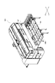
第1実施形態のレーザ加工機M1は、タレットパンチプレス加工装置とレーザ加工装置とが組合わされたパンチプレス・レーザ複合加工機[punch-pressing and laser-processing combined machine]である。図1(a)及び図1(b)に示されるように、レーザ加工機M1は、加工機本体[machine main body]10と、加工されるワークが載せられる加工テーブル(後述する固定テーブル14や移動テーブル15など)と、加工テーブルを覆う遮光性のカバー(後述する可動カバー30及び固定カバー40、キャビンとも呼ばれる)と、を有している。
加工機本体10は、レーザ加工ヘッド20及びパンチプレス加工のためのタレット12を備えている(図2参照)。レーザ加工時には、レーザ加工ヘッド20から加工テーブル上に載せられたワークW(図3及び図4参照)にレーザ光が照射され、ワークWがレーザ加工される。パンチプレス加工時には、ワークWを保持するキャリッジ18及び19(図2参照)を移動させながら、タレット12に装着された工具[tool](パンチ及びダイ[punches and dies])によってワークがパンチプレス加工される。
図2に示されるように、水平面内の互いに直交する2方向をX軸方向とY軸方向と定義したとき、レーザ加工機M1のX軸方向のほぼ中央には、タレット12及びレーザ加工ヘッド20を備えた加工機本体10が配置され、加工機本体10の下方には、固定テーブル13が配置される。また、加工機本体10のX軸方向の一側(図2の左側)には、移動テーブル15及び固定テーブル14が順に配置されている。加工機本体10の他側(図2の右側)にも、移動テーブル16及び固定テーブル17が順に配置されている。
加工機本体10は門形[gate-shaped]のフレーム11を有しており、フレーム11にタレット12が回転自在に設けられている。タレット12は、パンチが装着される上タレットと、ダイが装着される下タレットとを有している。タレット12は、パンチング加工時に、装着された工具を加工位置に位置決め[indexing]できるように構成されている。
フレーム11には、板状のワークWを支持する上述した固定テーブル13が設けられている。固定テーブル13の両側には、上述した移動テーブル15及び16がY軸方向に移動自在に設けられている。移動テーブル15及び16の外側には、それぞれ、上述した固定テーブル14及び17が設けられている。なお、固定テーブル13、14及び17と移動テーブル15及び16とで加工テーブルが構成されており、固定テーブルと移動テーブルとを区別しない場合は単に加工テーブルとも称することとする。
移動テーブル15及び16のそれぞれの一端は、X軸方向に延伸され、Y軸方向に移動可能なY軸キャリッジ18に連結されている。パンチング加工時には、Y軸キャリッジ18並びに移動テーブル15及び16は、Y軸方向に移動され、所望位置に位置決めされ得。
Y軸キャリッジ18には、X軸方向に移動可能なX軸キャリッジ19が設けられている。X軸キャリッジ19には、ワークWの端縁を把持するクランプ装置25が装着されている。従って、クランプ装置25は、Y軸方向に沿って所望位置に位置決めされたY軸キャリッジ18上でX軸方向に移動され、所望位置に位置決めされ得る。クランプ装置25は、矩形板状のワークWのX軸方向に延びる側縁(図2の下側縁)をクランプするように配置されている。
加工機本体10の一側の移動テーブル15の上方には、Y軸サブキャリッジ21が設けられている。レーザ加工ヘッド20は、Y軸サブキャリッジ21に取り付けられており、Y軸サブキャリッジ21に沿ってY軸方向に移動可能である。レーザ加工ヘッド20は、X軸方向及びY軸方向に直交するZ軸方向にも移動可能である。なお、図2及び図4では、レーザ加工ヘッド20は、Y軸サブキャリッジ21上における移動限界位置にそれぞれ示されている。
レーザ加工機M1でパンチプレス加工を行う場合、Y軸キャリッジ18及びX軸キャリッジ19によって、ワークWが加工位置へと移動されて、加工位置に位置決めされる。即ち、ワークWは、加工テーブル上に搬入され、原点位置決めされてから上述した側縁がクランプ装置25でクランプされる。クランプ装置25によってクランプされたワークWは、Y軸キャリッジ18及びX軸キャリッジ19によって加工位置へと移動され、加工位置に位置決めされる。加工位置に位置決めされたワークWは、パンチプレス加工される。
また、パンチプレス加工後にワークWの輪郭をレーザ切断する場合や、ワークWにレーザ切断などのレーザ加工のみを実施する場合は、Y軸キャリッジ18を原点位置に固定した状態で、Y軸サブキャリッジ21及びX軸キャリッジ19を移動させてレーザ加工が行われる。
次に、加工テーブルの上方に配設されたカバー(可動カバー30及び固定カバー40)の構造について説明する。
図1に示されるように、カバー(可動カバー30及び固定カバー40)は、レーザ加工範囲を覆い、レーザ光が外部に漏れないようにその内部を保護する。カバー(可動カバー30及び固定カバー40)は、その内部でキャリッジ18,19及び21の移動を可能にする大きさを有している。可動カバー30及び固定カバー40は、図2に示されるように、加工機本体10の両側の加工テーブル(固定テーブル14及び17、並びに、移動テーブル15及び16)上にそれぞれ設けられている。なお、図2には、固定カバー40は図示されていない。また、図1では、図2の左側の可動カバー30及び固定カバー40のみが見えており、右側の可動カバー30及び固定カバー40は加工機本体10の背後に隠れている。
固定カバー40は、加工機本体10の側部に固定されている。固定カバー40の側面には、Y軸方向に延びるガイドレール38が設けられている。また、固定カバー40のY軸方向の両端(又は、両端の一方のみ)には、必要時に上方に開放可能な傾斜された端部カバー42が設けられている。端部カバー42には、内部を視認するための窓44が設けられている。なお、端部カバー42は傾斜されていなくてもよいし、開放可能でなくてもよい。
一方、可動カバー30は、図1(a)に示される展開状態[deployed state]と、図1(b)に示される収納状態[retracted state]とに変更可能に構成されている。従って、可動カバー30は、加工テーブル(主に固定テーブル14)を覆う面積(広さ)を調整できる。また、可動カバー30は、Y軸方向に移動可能であり、加工テーブル(主に固定テーブル14)を覆う位置も変えることができる。
可動カバー30は、大きさの異なる分割カバー30A,30B及び30Cを順にY軸方向にスライド自在に組み合わせて構成されている。即ち、可動カバー30は、分割カバー30A,30B及び30Cが互いに重ならない展開状態と、分割カバー30A,30B及び30Cが互いに重ねられた収納状態とに変形可能[transformable]なテレスコピック型[telescopic type]のカバーである。分割カバー30A,30B及び30Cの展開や収納は、手動で行われてもよいし、エアシリンダや電動シリンダによって自動で行なわれてもよい。
固定カバー40の側面に設けられたガイドレール38と固定テーブル14の側縁に設けられたガイドレール36とには、分割カバー30A,30B及び30Cの係合部39及び37がそれぞれ係合されており、分割カバー30A,30B及び30CはY軸方向にそれぞれスライド可能である。
分割カバー30A,30B及び30Cは、それぞれ、固定テーブル14の上面に平行な水平板部[horizontal plate]31と、水平板部31の一縁部から下り傾斜された傾斜板部[slanted plate]32と、傾斜板部32の縁部から垂下された垂直板部[vertical plate]33とを有している。水平板部31の他縁部に、ガイドレール38とスライド可能に係合する上述した係合部39が設けられ、垂直板部33の下端内面に、ガイドレール36とスライド可能に係合する上述した係合部37が設けられている。
分割カバー30A,30B及び30Cの各傾斜板部32には、内部を視認するための遮光フィルタ付きの窓34が設けられている。なお、窓34は、立っている作業員が内部を広く視認可能な高さに配置されている。
図5(a)及び図5(b)に示されるように、分割カバー30Aの前縁には、次の分割カバー30Bの後縁のフランジ30Btと係合するフランジ30Asが設けられている。同様に、分割カバー30Bの前縁には、次の分割カバー30Cの後縁のフランジ30Ctと係合するフランジ30Bsが設けられている。これらのフランジ同士の係合によって、分割カバー30A,30B及び30Cの間の隙間からのレーザ光などの漏れが防止される。
図6(a)及び図6(b)に示されるように、可動カバー30を構成する分割カバー30A,30B及び30Cのうち、最も前に位置する分割カバー30Cの前端の下縁30aと固定テーブル14との間には、パスラインPLに沿うワークWの通過を許容する隙間30Pが形成される。ここで、昇降シャッタ51が、固定テーブル14の上面から突出可能に設けられている。昇降シャッタ51を上方に突出されることで隙間30Pが閉塞され、レーザ光が隙間30Pから外部に漏れるのが防止される。
昇降シャッタ51は、その不使用時には図6(b)に示されるように、固定テーブル14に設けられたスリット50の内部に収容され、その必要時には図6(a)に示されるように、エアシリンダ等の昇降機構52によって上昇させられる。このような機構によって、隙間30Pを遮蔽することができる。
図7(a)、図7(b)及び図8に示されるように、固定カバー40の端部カバー42近傍にはブラケット55が固定されており、ブラケット55には、センサ56が取り付けられている。センサ56は、分割カバー30Cの前端の下縁30aと、固定テーブル14上でY軸方向に移動されるワークWとの接触を検出する。本実施形態のセンサ56は、接触センサであり、その接触子56aの先端は、分割カバー30Cの下縁30aや端部カバー42の下縁42aより下方に突出され、外部から視認できる。センサ56は、反ったり引っかかったりしたワークWが分割カバー30Cの下縁30a等と接触する前に、それ自身の接触子56aをワークWと接触させ、ワークWとの接触を検出した時にはレーザ加工機M1が停止される。なお、センサ56は、加工テーブルの上方に配置されるのであれば、固定カバー40以外の位置に固定されてもよい。
次に、カバー(可動カバー30及び固定カバー40)の動作について説明する。
必要に応じて可動カバー30の大きさを調整することで、ワークWの搬入出を容易に行うことができる。例えば、図3に示されるように、第1原点に位置決めしながらワークWを搬入又は搬出する場合、可動カバー30を収納(全開)状態にして、クランプ装置25を用いてワークWを搬入又は搬出することができる。
あるいは、図4に示されるように、第2原点に位置決めしながらワークWを搬入又は搬出する場合、可動カバー30を収納(全閉)状態にし、かつ、Y軸キャリッジ18を前進させて、クランプ装置25を用いてワークWを搬入又は搬出することができる。
また、レーザ加工時には、X軸キャリッジ19によってワークWをX軸方向に移動させ、かつ、レーザ加工ヘッド20をY軸サブキャリッジ21に沿ってY軸方向に移動させることで、X-Y平面内でレーザ加工が行われる。レーザ加工時にはワークWはX軸方向にのみ移動されるので、ワークWの移動範囲は可動カバー30で覆われ、レーザ光が遮光される。なお、レーザ加工時には、図6(a)に示されるように、昇降シャッタ51が上昇されて、上述した隙間30Pが遮蔽される。
また、パンチプレス加工時には、X軸キャリッジ19によってワークWをX軸方向に移動させ、かつ、Y軸キャリッジ18によってワークWをY軸方向に移動させることで、パンチプレス加工が行われる。パンチプレス加工時にはワークWはX軸方向及びY軸方向に移動されるので、図6(b)に示されるように、昇降シャッタ51が下降されてs、上述した隙間30Pが開放され、ワークWは隙間30Pを通過できる。
図8に示されるように、ワークWの移動時には、センサ56によってワークWと分割カバー30Cの下縁30a等との接触を事前に検出してレーザ加工機M1を停止させることができる。従って、可動カバー30やY軸キャリッジ18等の破損を確実に防止することができる。
本実施形態のレーザ加工機M1では、加工テーブル(固定テーブル14及び17)の上面を覆う遮光性の可動カバー30によって、加工テーブルの上面を覆う面積を調整できる。即ち、可動カバー30の大きさを調整することで、レーザ加工の範囲のみを可動カバー30で覆うことができる。従って、レーザ光の遮光性、加工時に生じる音の遮音性、加工時に生じるスパッタや塵埃等の防塵性を維持しつつ、可動カバー30をコンパクトに構成することができる(加工テーブルの全面を覆うフルカバーや、一定の大きさを有するカバーに比べて)。この結果、可動カバー30の軽量化及び低コスト化を実現することができる。
また、ワークWの搬入又は搬出時には、図3及び図4に示されるように、ワークWの搬入又は搬出に必要な範囲で可動カバー30を開いておくことができるので、ワークWの搬入又は搬出を容易に行うことができる。
また、可動カバー30は、その大きさに加えて、その位置も変えることができるので、レーザ加工時に必要な範囲のみを効率よく保護することができる。
また、可動カバー30は、テレスコピック型のカバーとして構成されているので、簡単な構造で構成され得ると共に、簡単に操作され得る。そして、可動カバー30は、展開状態と収納状態とに変形可能であり、加工テーブルの上面を覆う面積を容易に調整することができる。
また、可動カバー30には遮光フィルタ付きの窓34が設けられているので、レーザ加工中にその内部の様子を視認することができる。
また、昇降シャッタ51を上昇させることで、可動カバー30の下縁30aと加工テーブルとの間の隙間30Pからレーザ光が外部に漏れるのを防止できる。一方、昇降シャッタ51を下降させることで、可動カバー30で加工テーブルを覆ったままワークWを移動させることができる。なお、昇降シャッタ51は、ワークWと接触することがないので、消耗も少なく耐久性に優れる。従来は、可撓性シートで隙間を閉塞していた(上記特許文献1参照)が、可撓性シートはワークと接触するので耐久性に劣る。
本実施形態のレーザ加工機(パンチプレス・レーザ複合加工機)M1では、タレットパンチプレス加工中に、ワークWを保持するキャリッジ18及び19を可動カバー30内で自由に動かすことができるので、主としてレーザ加工のために設けた可動カバー30がパンチプレス加工中に邪魔にならない。なお、可動カバー30によって、パンチプレス加工時に生じる音を遮音することができる。
また、センサ56によってワークWの反りや引っかかり等を検出することで、ワークWと分割カバー30Cの下縁30aとが接触する前に、パンチ・レーザ複合加工機M1を停止させることができるので、可動カバー30やY軸キャリッジ18等の破損を確実に防止することができる。
次に、第2実施形態のレーザ加工機M2について説明する。図9(a)及び図9(b)に示されるように、レーザ加工機M2は、レーザ加工のみ行う単機能加工機である。レーザ加工機M2は、加工機本体60と、加工されるワークが載せられる加工テーブル64と、加工テーブル64を覆う遮光性のカバー(可動カバー80)と、を有している。
加工機本体60には、Y軸方向に移動可能なキャレッジ(図示略)と、水平面内でY軸方向に直交するX軸方向に移動可能なレーザ加工ヘッド(図示略)とが設けられている。加工テーブル64は、Y軸方向に沿って設けられている。加工テーブル64上に載せられたワークにレーザ光が照射され、ワークがレーザ加工される。
加工テーブル64の上方に配設された可動カバー80は、図9(a)に示される収納状態と、図9(b)に示される展開状態とに変更可能に構成されている。従って、可動カバー80は、加工テーブル64を覆う面積を調整できる。また、可動カバー80は、Y軸方向に移動可能であり、加工テーブル64を覆う位置も変えることができる。
可動カバー80は、大きさの異なる複数の分割カバー80A,80B,80C及び80Dを順にY軸方向にスライド自在に組み合わせて構成されている。即ち、可動カバー80は、分割カバー80A,80B,80C及び80Dが互いに重ならない展開状態と、可動カバー80は、分割カバー80A,80B,80C及び80Dが互いに重ねられた収納状態とに変形可能なテレスコピック型のカバーである。
なお、分割カバー80A,80B,80C及び80Dは、スライドレール66に沿ってY軸方向にスライド可能に配設されている。分割カバー80A,80B,80C及び80Dの展開や収納は、手動で行われてもよいし、エアシリンダや電動シリンダによって自動で行なわれてもよい。また、図9(b)に示されるように、分割カバー80Dの下縁と加工テーブル64との間の隙間は、昇降シャッタ81により開閉される。
本実施形態のレーザ加工機M2でも、加工テーブル64の上面を覆う遮光性の可動カバー80によって、加工テーブル64の上面を覆う面積を調整できる。即ち、可動カバー80の大きさを調整することで、レーザ加工の範囲のみを可動カバー80で覆うことができる。従って、レーザ光の遮光性、加工時に生じる音の遮音性、加工時に生じるスパッタや塵埃等の防塵性を維持しつつ、可動カバー80をコンパクトに構成することができる(加工テーブルの全面を覆うフルカバーや、一定の大きさを有するカバーに比べて)。この結果、可動カバー80の軽量化及び低コスト化を実現することができる。
また、ワークWの搬入又は搬出時には、ワークWの搬入又は搬出に必要な範囲で可動カバー80を開いておくことができるので、ワークWの搬入又は搬出を容易に行うことができる。
また、可動カバー80は、その大きさに加えて、その位置も変えることができるので、レーザ加工時に必要な範囲のみを効率よく保護することができる。
また、可動カバー80は、テレスコピック型のカバーとして構成されているので、簡単な構造で構成され得ると共に、簡単に操作され得る。そして、可動カバー80は、展開状態と収納状態と変更可能であり、加工テーブル64の上面を覆う面積を容易に調整することができる。
以下、図10~図13に示された他の実施形態について説明する。
図10に示される第3実施形態のレーザ加工機M3では、Y軸方向にスライド可能なカバー(可動カバー130)が設けられている。展開状態の可動カバー130は、加工テーブルの上面の全範囲を覆う。符号131は収納状態の位置を示している。
図11に示される第4実施形態のレーザ加工機M4では、X軸方向にスライド可能なカバー(可動カバー140)が設けられている。展開状態の可動カバー140は、加工テーブルの上面の全範囲を覆う。符号141は収納状態の位置を示している。
図12に示される第5実施形態のレーザ加工機M5では、X軸方向に展開可能で、かつ、収納可能なカバー(可動カバー150)が設けられている。収納状態の可動カバー150は、加工テーブル14の下方に収納される。符号151は収納状態の位置を示している。
図13に示される第6実施形態のレーザ加工機M6では、X軸方向に展開可能で、かつ、収納可能なカバー(可動カバー160)が設けられている。符号161は収納状態の位置を示している。
Claims (7)
- レーザ加工機であって、
レーザ加工ヘッドを有する加工機本体と、
加工すべきワークを載せる加工テーブルと、
前記加工テーブルの上方に設けられ、前記加工テーブルの上面を覆う遮光性のカバーとを備えており、
前記カバーは、展開状態と収納状態とに変形可能で、前記加工テーブルの上面を覆う面積を調整可能である、レーザ加工機。 - 請求項1に記載のレーザ加工機であって、
前記カバーが、前記加工テーブルを覆う位置も変えることができる、レーザ加工機。 - 請求項1又は2に記載のレーザ加工機であって、
前記カバーが、大きさの異なる複数の分割カバーを順にスライド自在に組み合わせて構成されることで、前記展開状態と前記収納状態とに変形可能なテレスコピック型のカバーである、レーザ加工機。 - 請求項1~3の何れか一項に記載のレーザ加工機であって、
前記カバーに、遮光フィルタ付きの窓が設けられている、レーザ加工機。 - 請求項1~4の何れか一項に記載のレーザ加工機であって、
前記カバーの下縁と前記加工テーブルとの間に、前記ワークの通過を許容する隙間が形成されており、
上方に突出された状態で前記隙間を遮蔽する昇降シャッタが、前記加工テーブルの上面から突出可能に設けられている、レーザ加工機。 - 請求項1~5の何れか一項に記載のレーザ加工機であって、
前記加工テーブルの上方に設けられ、前記加工テーブル上を移動する前記ワークとの接触を検出するセンサをさらに備えている、レーザ加工機。 - 請求項1~6の何れか一項に記載のレーザ加工機であって、
前記カバーの内部で移動可能な、前記ワークを保持するキャリッジと、
前記キャリッジを移動させながら前記ワークにタレットパンチプレス加工を行うタレットをさらに備えている、レーザ加工機。
Priority Applications (2)
| Application Number | Priority Date | Filing Date | Title |
|---|---|---|---|
| US15/029,753 US10300553B2 (en) | 2013-10-31 | 2014-10-09 | Laser processing machine |
| EP14857259.7A EP3064308B1 (en) | 2013-10-31 | 2014-10-09 | Laser processing machine |
Applications Claiming Priority (4)
| Application Number | Priority Date | Filing Date | Title |
|---|---|---|---|
| JP2013-226231 | 2013-10-31 | ||
| JP2013226231 | 2013-10-31 | ||
| JP2014-174080 | 2014-08-28 | ||
| JP2014174080A JP6438710B2 (ja) | 2013-10-31 | 2014-08-28 | レーザ加工機 |
Publications (1)
| Publication Number | Publication Date |
|---|---|
| WO2015064332A1 true WO2015064332A1 (ja) | 2015-05-07 |
Family
ID=53003943
Family Applications (1)
| Application Number | Title | Priority Date | Filing Date |
|---|---|---|---|
| PCT/JP2014/077057 Ceased WO2015064332A1 (ja) | 2013-10-31 | 2014-10-09 | レーザ加工機 |
Country Status (4)
| Country | Link |
|---|---|
| US (1) | US10300553B2 (ja) |
| EP (1) | EP3064308B1 (ja) |
| JP (1) | JP6438710B2 (ja) |
| WO (1) | WO2015064332A1 (ja) |
Cited By (1)
| Publication number | Priority date | Publication date | Assignee | Title |
|---|---|---|---|---|
| CN107350809A (zh) * | 2017-08-31 | 2017-11-17 | 南通大学 | 一种铁钻工冲扣钳辊子结构化表面的制备装置及制备方法 |
Families Citing this family (14)
| Publication number | Priority date | Publication date | Assignee | Title |
|---|---|---|---|---|
| EP2886242B1 (de) * | 2013-12-20 | 2016-09-14 | TRUMPF Werkzeugmaschinen GmbH + Co. KG | Laserbearbeitungsmaschinen-Anordnung, insbesondere mit barrierefreiem Zugang |
| JP6582631B2 (ja) * | 2015-07-03 | 2019-10-02 | 村田機械株式会社 | 板材加工システム、及び板材加工方法 |
| JP6546838B2 (ja) * | 2015-11-18 | 2019-07-17 | 株式会社アマダホールディングス | 複合加工機 |
| DE102016204161B4 (de) | 2016-03-14 | 2017-10-19 | Trumpf Werkzeugmaschinen Gmbh + Co. Kg | Laserbearbeitungsmaschine |
| USD850500S1 (en) * | 2016-08-31 | 2019-06-04 | Trumpf Gmbh + Co. Kg | Machine tool |
| JP6975008B2 (ja) * | 2017-10-06 | 2021-12-01 | 日酸Tanaka株式会社 | 突出部検出装置、切断装置 |
| USD921071S1 (en) * | 2018-03-26 | 2021-06-01 | Hk Co., Ltd. | Housing for laser machining center |
| BE1026343B1 (nl) * | 2018-06-05 | 2020-01-14 | Lvd Co | Afscherminrichting voor een bewerkingsmachine |
| USD868854S1 (en) * | 2018-10-11 | 2019-12-03 | Electro Scientific Industries, Inc | Laser processing machine |
| DE202018105888U1 (de) * | 2018-10-15 | 2019-01-15 | Sato Schneidsysteme Anton Hubert E.K. | Vorrichtung zur Einhausung |
| JP7310686B2 (ja) * | 2020-04-03 | 2023-07-19 | 新東工業株式会社 | レーザ刻印装置、レーザ刻印システム及びレーザ刻印方法 |
| USD965651S1 (en) * | 2020-07-07 | 2022-10-04 | Trumpf Gmbh + Co. Kg | Machine tool for metal working |
| JP7569761B2 (ja) * | 2021-08-06 | 2024-10-18 | 株式会社アマダ | レーザ加工機及び遮光用台車 |
| CN116370165B (zh) * | 2023-03-30 | 2023-12-29 | 中国人民解放军总医院第三医学中心 | 一种多孔隙生物羊膜穿刺设备及制备方法 |
Citations (10)
| Publication number | Priority date | Publication date | Assignee | Title |
|---|---|---|---|---|
| JPH06226480A (ja) * | 1993-02-05 | 1994-08-16 | Murata Mach Ltd | レーザヘッド高さ制御装置 |
| JPH09271988A (ja) * | 1996-04-10 | 1997-10-21 | Amada Co Ltd | 熱切断加工機 |
| JPH09295180A (ja) | 1996-04-30 | 1997-11-18 | Amada Co Ltd | レーザ加工機 |
| JPH11333580A (ja) * | 1998-05-25 | 1999-12-07 | Amada Co Ltd | レーザー加工におけるワーク位置決め方法及びワーク位置決め装置 |
| JP2000052075A (ja) * | 1998-08-03 | 2000-02-22 | Shachihata Inc | レーザ加工機 |
| JP2000351032A (ja) * | 1999-06-11 | 2000-12-19 | Murata Mach Ltd | 板材搬送装置 |
| JP2001208513A (ja) * | 2000-01-27 | 2001-08-03 | Amada Co Ltd | 駆動装置における変位量検出方法及びその装置、並びに板材加工機における高品質加工方法及び高品質加工システム |
| JP2005028395A (ja) * | 2003-07-09 | 2005-02-03 | Amada Co Ltd | パンチ・レーザ複合加工機 |
| JP2013035006A (ja) * | 2011-08-05 | 2013-02-21 | Amada Co Ltd | 遮光板損傷検出方法及び装置 |
| WO2013037927A1 (de) * | 2011-09-16 | 2013-03-21 | Trumpf Laser Gmbh + Co. Kg | Laserbearbeitungsmaschine mit einer schutztüre und eine steuereinrichtung |
Family Cites Families (9)
| Publication number | Priority date | Publication date | Assignee | Title |
|---|---|---|---|---|
| JPH05337675A (ja) | 1992-06-03 | 1993-12-21 | Topcon Corp | レーザー加工装置 |
| JP3125540B2 (ja) * | 1993-11-10 | 2001-01-22 | 富士ゼロックス株式会社 | 画像形成装置及び画像形成装置のフレーム |
| JPH0957438A (ja) * | 1995-08-28 | 1997-03-04 | Komatsu Ltd | 熱切断加工機の集塵装置 |
| JPH0966386A (ja) * | 1995-08-31 | 1997-03-11 | Amada Co Ltd | レーザ加工機 |
| KR100315007B1 (ko) * | 1995-11-22 | 2002-02-28 | 이시다 아키라 | 카세트내의 기판 검출 및 반송장치와 그 방법 |
| JP2004202533A (ja) | 2002-12-25 | 2004-07-22 | Amada Co Ltd | 複合加工機 |
| DE102008019095B3 (de) * | 2008-04-11 | 2009-08-13 | Jenoptik Automatisierungstechnik Gmbh | Laserbearbeitungsanlage mit einer Schutzeinhausung |
| PL216793B1 (pl) * | 2010-12-13 | 2014-05-30 | Tadeusz Eckert | Przecinarka |
| CN202813202U (zh) * | 2012-09-04 | 2013-03-20 | 芜湖长信科技股份有限公司 | Uv硬化机遮光机构 |
-
2014
- 2014-08-28 JP JP2014174080A patent/JP6438710B2/ja active Active
- 2014-10-09 WO PCT/JP2014/077057 patent/WO2015064332A1/ja not_active Ceased
- 2014-10-09 US US15/029,753 patent/US10300553B2/en active Active
- 2014-10-09 EP EP14857259.7A patent/EP3064308B1/en active Active
Patent Citations (10)
| Publication number | Priority date | Publication date | Assignee | Title |
|---|---|---|---|---|
| JPH06226480A (ja) * | 1993-02-05 | 1994-08-16 | Murata Mach Ltd | レーザヘッド高さ制御装置 |
| JPH09271988A (ja) * | 1996-04-10 | 1997-10-21 | Amada Co Ltd | 熱切断加工機 |
| JPH09295180A (ja) | 1996-04-30 | 1997-11-18 | Amada Co Ltd | レーザ加工機 |
| JPH11333580A (ja) * | 1998-05-25 | 1999-12-07 | Amada Co Ltd | レーザー加工におけるワーク位置決め方法及びワーク位置決め装置 |
| JP2000052075A (ja) * | 1998-08-03 | 2000-02-22 | Shachihata Inc | レーザ加工機 |
| JP2000351032A (ja) * | 1999-06-11 | 2000-12-19 | Murata Mach Ltd | 板材搬送装置 |
| JP2001208513A (ja) * | 2000-01-27 | 2001-08-03 | Amada Co Ltd | 駆動装置における変位量検出方法及びその装置、並びに板材加工機における高品質加工方法及び高品質加工システム |
| JP2005028395A (ja) * | 2003-07-09 | 2005-02-03 | Amada Co Ltd | パンチ・レーザ複合加工機 |
| JP2013035006A (ja) * | 2011-08-05 | 2013-02-21 | Amada Co Ltd | 遮光板損傷検出方法及び装置 |
| WO2013037927A1 (de) * | 2011-09-16 | 2013-03-21 | Trumpf Laser Gmbh + Co. Kg | Laserbearbeitungsmaschine mit einer schutztüre und eine steuereinrichtung |
Non-Patent Citations (1)
| Title |
|---|
| See also references of EP3064308A4 |
Cited By (1)
| Publication number | Priority date | Publication date | Assignee | Title |
|---|---|---|---|---|
| CN107350809A (zh) * | 2017-08-31 | 2017-11-17 | 南通大学 | 一种铁钻工冲扣钳辊子结构化表面的制备装置及制备方法 |
Also Published As
| Publication number | Publication date |
|---|---|
| EP3064308B1 (en) | 2019-08-21 |
| JP6438710B2 (ja) | 2018-12-19 |
| EP3064308A4 (en) | 2017-05-10 |
| EP3064308A1 (en) | 2016-09-07 |
| US10300553B2 (en) | 2019-05-28 |
| US20160228982A1 (en) | 2016-08-11 |
| JP2015110243A (ja) | 2015-06-18 |
Similar Documents
| Publication | Publication Date | Title |
|---|---|---|
| JP6438710B2 (ja) | レーザ加工機 | |
| US10427253B2 (en) | Machine tool having a workpiece support and method for loading and unloading a workpiece support of a machine tool | |
| KR101645623B1 (ko) | 판재 반송 설비 및 그것을 사용한 판재 가공 시스템 | |
| KR102054736B1 (ko) | 판금 가공 시스템 및 이를 이용한 판금 가공 방법 | |
| TW201544228A (zh) | 工具機 | |
| US10456862B2 (en) | Plate processing system and plate processing method | |
| KR20150052308A (ko) | 작업편을 가공하기 위한 기계 공구 및 방법 | |
| EP2514557A2 (en) | Set-up station door apparatus for machine tool | |
| JP5949359B2 (ja) | ローダ装置 | |
| KR20140110160A (ko) | 공작기계 | |
| CN108367403A (zh) | 复合加工装置和复合加工方法 | |
| CN107530855B (zh) | 工件装卸装置 | |
| JP6618544B2 (ja) | 多機能ワーク置き台モジュール | |
| JP6582631B2 (ja) | 板材加工システム、及び板材加工方法 | |
| JP6895353B2 (ja) | レーザ加工装置 | |
| CN107962687A (zh) | 一种加工中心和切磨加工中心设备 | |
| TWM548608U (zh) | 工具更換裝置 | |
| JP2008296294A (ja) | パレット交換装置 | |
| EP2246165B1 (en) | Working machine for wood or similar materials | |
| JP2014188566A (ja) | プレス加工装置 | |
| CN223916960U (zh) | 镭射切割设备 | |
| CN221389992U (zh) | 一种龙门直角铣头储存仓 | |
| JP5855962B2 (ja) | 加工システム | |
| TWM536994U (zh) | 工具機頂罩自動門裝置 | |
| KR20260001884A (ko) | 공작기계의 가공영역 차폐장치 |
Legal Events
| Date | Code | Title | Description |
|---|---|---|---|
| 121 | Ep: the epo has been informed by wipo that ep was designated in this application |
Ref document number: 14857259 Country of ref document: EP Kind code of ref document: A1 |
|
| WWE | Wipo information: entry into national phase |
Ref document number: 15029753 Country of ref document: US |
|
| REEP | Request for entry into the european phase |
Ref document number: 2014857259 Country of ref document: EP |
|
| WWE | Wipo information: entry into national phase |
Ref document number: 2014857259 Country of ref document: EP |
|
| NENP | Non-entry into the national phase |
Ref country code: DE |