WO2015064352A1 - コネクタ - Google Patents
コネクタ Download PDFInfo
- Publication number
- WO2015064352A1 WO2015064352A1 PCT/JP2014/077305 JP2014077305W WO2015064352A1 WO 2015064352 A1 WO2015064352 A1 WO 2015064352A1 JP 2014077305 W JP2014077305 W JP 2014077305W WO 2015064352 A1 WO2015064352 A1 WO 2015064352A1
- Authority
- WO
- WIPO (PCT)
- Prior art keywords
- housing
- cover
- wire
- outer peripheral
- fitting
- Prior art date
- Legal status (The legal status is an assumption and is not a legal conclusion. Google has not performed a legal analysis and makes no representation as to the accuracy of the status listed.)
- Ceased
Links
Images




Classifications
-
- H—ELECTRICITY
- H01—ELECTRIC ELEMENTS
- H01R—ELECTRICALLY-CONDUCTIVE CONNECTIONS; STRUCTURAL ASSOCIATIONS OF A PLURALITY OF MUTUALLY-INSULATED ELECTRICAL CONNECTING ELEMENTS; COUPLING DEVICES; CURRENT COLLECTORS
- H01R13/00—Details of coupling devices of the kinds covered by groups H01R12/70 or H01R24/00 - H01R33/00
- H01R13/58—Means for relieving strain on wire connection, e.g. cord grip, for avoiding loosening of connections between wires and terminals within a coupling device terminating a cable
- H01R13/5804—Means for relieving strain on wire connection, e.g. cord grip, for avoiding loosening of connections between wires and terminals within a coupling device terminating a cable comprising a separate cable clamping part
- H01R13/5812—Means for relieving strain on wire connection, e.g. cord grip, for avoiding loosening of connections between wires and terminals within a coupling device terminating a cable comprising a separate cable clamping part the cable clamping being achieved by mounting the separate part on the housing of the coupling device
-
- H—ELECTRICITY
- H01—ELECTRIC ELEMENTS
- H01R—ELECTRICALLY-CONDUCTIVE CONNECTIONS; STRUCTURAL ASSOCIATIONS OF A PLURALITY OF MUTUALLY-INSULATED ELECTRICAL CONNECTING ELEMENTS; COUPLING DEVICES; CURRENT COLLECTORS
- H01R13/00—Details of coupling devices of the kinds covered by groups H01R12/70 or H01R24/00 - H01R33/00
- H01R13/44—Means for preventing access to live contacts
- H01R13/447—Shutter or cover plate
-
- H—ELECTRICITY
- H01—ELECTRIC ELEMENTS
- H01R—ELECTRICALLY-CONDUCTIVE CONNECTIONS; STRUCTURAL ASSOCIATIONS OF A PLURALITY OF MUTUALLY-INSULATED ELECTRICAL CONNECTING ELEMENTS; COUPLING DEVICES; CURRENT COLLECTORS
- H01R13/00—Details of coupling devices of the kinds covered by groups H01R12/70 or H01R24/00 - H01R33/00
- H01R13/62—Means for facilitating engagement or disengagement of coupling parts or for holding them in engagement
- H01R13/621—Bolt, set screw or screw clamp
- H01R13/6215—Bolt, set screw or screw clamp using one or more bolts
Definitions
- the present invention relates to a connector.
- the connector described in Patent Document 1 includes a housing having a wire lead-out surface (wire lead-out surface) from which a wire is drawn, and a wire cover attached to the housing so as to cover the wire lead-out surface of the housing.
- the wire cover has a cap-like shape, and a cover lock portion is provided at the opening edge thereof.
- a housing lock portion is provided on the outer peripheral edge of the wire lead-out surface of the housing.
- a housing having a wire lead-out surface from which a wire is drawn out and an outer peripheral surface arranged to intersect with the wire lead-out surface, and the wire drawer of the housing attached to the housing while arranging the wire inside. It has a cover body portion arranged to cover the surface, is integrally connected to the cover body portion, is fitted so as to cover the outer peripheral surface of the housing, and rotates around an axis in the fitting direction And a wire cover having a fitting cylindrical portion which is kept in a restricted state.
- the fitting cylindrical portion of the wire cover covers the outer peripheral surface of the housing
- the wire cover is prevented from coming out of the housing since it is fitted in and kept restricted from rotating about the axis in the fitting direction.
- the outer peripheral surface of the housing is covered by the fitting cylinder portion, a situation where the outer peripheral surface of the housing is damaged can be prevented.
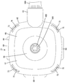
- Example of this invention it is a principal part fracture side view showing the state in which the wire cover was attached to the housing. It is a principal part fracture side view showing the state where a housing was fitted by other party housing. It is a rear view of a connector. It is a rear view of a housing. It is a front view of a wire cover. It is a side view of a wire cover.
- FIG. 5 is a cross-sectional view of a housing in which a bolt is mounted.
- a cover lock portion which is located on the opposite side to the electric wire drawing surface in the housing and is hooked and locked on an outer peripheral side of a mating surface facing the mating housing when mating with the mating housing; have. With such a configuration, the shape of the housing that receives the cover lock portion does not have to be complicated.
- the cover main body portion has a front view shape in which a square portion protrudes outward, and the cover lock portion is disposed at a position facing the square portion of the cover main body portion.
- the wire cover is less likely to be detached from the housing.
- a housing lock portion engageable with the cover lock portion is provided on the outer peripheral side of the fitting surface of the housing, and the housing lock portion is another one on the outer peripheral side of the fitting surface of the housing. It is arranged continuously in line with the part. Therefore, the housing lock portion does not have to be specially shaped, and the conventional housing can be used as it is.
- the housing is bolted to the mating housing.
- the connector becomes large and the electric wire also tends to be large in diameter, and the vibration force of the electric wire tends to be transmitted to the electric wire cover largely.
- deviates from a housing becomes large.
- the fitting cylindrical portion is fitted so as to cover the entire portion of the outer peripheral surface of the housing except the portion corresponding to the portion from which the electric wire is led out.
- the wire cover has a guide portion integrally connected to the cover body portion and protruding in a direction intersecting the fitting cylinder portion, and the wire drawn from the wire lead-out surface is fixed to the guide portion There is.
- the connector 10 of the embodiment includes a housing 20, a wire cover 60 attached to the housing 20, and a terminal fitting 90 housed in the housing 20.
- the housing 20 is engageable with the mating housing 100.
- the housing 20 faces the mating housing 100 at the start of mating with the mating housing 100 (on the side of the mating surface 26 described later, as shown in FIGS.
- the lower side of 6 and FIG. 7 is the front, and in the vertical direction, the left side of each figure is the upper side, and the right side of each figure is the lower side.
- the mating housing 100 is made of synthetic resin and, as shown in FIG. 2, has a longitudinally elongated form as a whole.
- a mating terminal fitting (not shown) is accommodated inside the mating housing 100, and a nut 200 is attached to the center thereof.
- the nut 200 is positioned in the front-rear direction with respect to the mating housing 100, and is held in a state in which the rotation around the axis in the front-rear direction is restricted.
- the housing 20 is made of synthetic resin and, as shown in FIG. 7, has a generally elongated shape in the vertical direction as a whole, and has a block-like housing main body 21 and a cylindrical hood 22 surrounding the housing main body 21. And.
- the space between the housing body 21 and the hood 22 is opened forward as a fitting space 50 in which the mating housing 100 enters from the front.
- a seal ring 300 is fitted on the outer peripheral surface of the housing body 21.
- the seal ring 300 is elastically held between the housing body 21 and the hood 22.
- protrusions 23 for forming a locking structure for retaining the seal ring 300 are provided on the upper and lower surfaces and the front and rear surfaces of the hood portion 22.
- a housing lock portion 25 which can be engaged with a cover lock portion 72 described later is provided at the front end of the hood portion 22 (the outer peripheral side of the fitting surface 26 described later of the housing 20). ing.
- the housing lock portion 25 is disposed continuously and flush with the other portion of the front end of the hood portion 22 and does not have a specific shape.
- the front surface of the housing 20 is configured as a fitting surface 26 facing the mating housing 100 at the time of fitting, and the rear surface of the housing 20 opposite to the fitting surface 26 is
- the electric wire 500 is configured as an electric wire lead-out surface 27 from which the electric wire 500 is drawn.
- the housing 20 has an outer peripheral surface 28 facing the back, which intersects the surface direction of the fitting surface 26 and the wire drawing surface 27 between the fitting surface 26 and the wire drawing surface 27.
- a plurality of cavities 29 into which the terminal fitting 90 can be inserted are provided in the housing 20. Each of the cavities 29 extends in the front-rear direction, and both front and rear ends thereof are opened to the fitting surface 26 and the wire lead-out surface 27, respectively.
- the housing 20 is provided with a through hole 31 extending in the front-rear direction and opening at the central portion of each of the wire drawing surface 27 and the fitting surface 26.
- a cylindrical pedestal portion 32 surrounding the through hole 31 is provided to project rearward.
- the shaft portion 410 of the bolt 400 is attached to the through hole 31 in a fitted state.
- a head 420 having a hexagonal shape in a rear view is formed so as to radially extend from the rear end of a shaft portion 410 extending in the longitudinal direction.
- the head 420 is arranged to project rearward from the wire drawing surface 27 of the housing 20 in a state supported by the rear end of the pedestal 32. Are disposed so as to project further forward than the fitting surface 26 of the housing 20.
- a screw capable of being screwed with the nut 200 is cut.
- the shaft portion 410 of the bolt 400 is inserted into the nut 200 in a state in which the two housings 20 and 100 are shallowly fitted.
- a tool (not shown) is fitted to the head 420 of the bolt 400 to rotate the tool.
- the shaft portion 410 of the bolt 400 is screwed into the nut 200.
- the wire cover 60 is also made of a synthetic resin, and is in the form of a cap as a whole, and is attached to the housing 20 from the rear.
- the wire cover 60 has a cover main body 61 having a substantially rectangular outer peripheral edge such that the square part protrudes outward when viewed from the back or front, and the cover main body 61
- a guide portion 62 integrally extending to the portion 61 and projecting downward, and a cylindrical fitting cylindrical portion 63 integrally projecting to the front of the cover main body portion 61 are provided. ing.
- the cover main body portion 61 is rearward from the outer peripheral edge of the electric wire lead-out surface 27 of the housing 20 (in a direction away from the electric wire lead-out surface 27) with the electric wire cover 60 attached to the housing 20. It extends forward from the inner peripheral edge of the rear wall 65 extending in the direction of the wire lead surface 27 from the inner peripheral edge of the rear wall 65. It consists of a cylindrical tubular portion 66. The lower surface side of the outer peripheral wall portion 64 is formed with an outlet port 67 which is formed by cutting a part in the circumferential direction.
- the guide portion 62 is a projecting piece having an arc-shaped cross section that extends downward from the opening rear edge of the outlet 67. As shown in FIG.
- each electric wire 500 drawn out from the electric wire drawing surface 27 of the housing 20 is turned within the electric wire cover 60 and then taken out from the electric wire cover 60 along the guide portion 62 from the outlet 67. It is done. At this time, each electric wire 500 is tape-wound and fixed to the guide portion 62.
- the cylindrical portion 66 has a configuration in which the central portion of the outer surface of the cover main body portion 61 is recessed, and the recessed space is a working space 68 into which a tool for bolt fastening can be inserted.
- the front end opening edge of the cylindrical portion 66 is disposed so as to surround the pedestal portion 32 of the housing 20.
- the fitting cylindrical portion 63 is configured to project forward from a portion of the front end of the outer peripheral wall portion 64 excluding the position corresponding to the outlet 67, and as shown in FIGS. It has the bulging part 69 bulging outward on both sides. As shown in FIG. 1 and FIG. 2, the inner surface of the bulging portion 69 is arranged in a stepped manner at the front end of the outer peripheral wall portion 64.
- the fitting cylindrical portion 63 is fitted so as to cover substantially the entire portion of the outer peripheral surface 28 of the hood portion 22 except the portion corresponding to the outlet 67 in a state where the wire cover 60 is attached to the housing 20 Be In this case, the bulging portion 69 is disposed so as to surround the protrusion 23 of the hood portion 22.
- the fitting cylinder 63 extends in the front-rear direction on both sides in the circumferential direction across the upper two corners apart from the guide 62 in the square part and opens at the front end.
- a slit 71 is provided in each of the square parts of the fitting cylindrical portion 63.
- cover lock portions 72 are provided so as to be flexible between the slits 71 facing each other in the circumferential direction and the lower two corners facing the gaps between the slits 71.
- the cover lock portion 72 has a cross-sectional shape curving in an arc shape along a square portion of the fitting cylindrical portion 63.
- the front end of the cover lock portion 72 is disposed at the same longitudinal position as the other portions of the front end of the fitting cylindrical portion 63. And as shown in FIG. 5, the front end part of the cover lock part 72 is provided with the nail
- the lock protrusion 73 of the cover lock portion 72 elastically abuts on the housing lock portion 25 at the front end of the hood portion 22, whereby the wire cover 60 is fitted to the housing 20 It is held in the state.
- each wire 500 is drawn out from the wire lead-out surface 27 and arranged.
- the wire cover 60 is attached to the housing 20.
- the lock projections 73 of the cover lock portions 72 slide on the outer peripheral surface 28 of the housing 20, and the cover lock portions 72 are bent and deformed outward.
- each cover lock portion 72 elastically returns, and the lock projection 73 is arranged to be able to be locked to the corresponding housing lock portion 25.
- the lock protrusion 73 of each cover lock portion 72 wraps around a square portion on the outer peripheral side of the fitting surface 26 of the housing 20, and the housing 20 is substantially held by the wire cover 60.
- the fitting cylindrical portion 63 is externally fitted to the housing 20 In this state, rotation about the axis in the front-rear direction (the fitting direction of the fitting cylindrical portion 63 with respect to the housing 20) with respect to the housing 20 is restricted. Therefore, even if an impact such as an external force is applied to the wire cover 60, the position of the wire cover 60 relative to the housing 20 does not shift about the axis, and the cover lock portion 72 corresponds to the corresponding housing lock portion 25. The locked state is maintained.
- the wires 500 are shaken largely inclined in the direction crossing the original lead-out direction.
- An excessive twisting force acting on the wire cover 60 via the guide portion 62 causes the relative position with the housing 20 to be shifted about the axis.
- the fitting cylindrical portion 63 is fitted so as to cover the outer peripheral surface 28 of the housing 20 and is maintained in a state of being restricted from rotating about the longitudinal axis. 60 is held firmly in the housing 20 against torsional forces. Therefore, the twisting force does not act directly on the cover lock portion 72, and the locked state of the cover lock portion 72 and the housing lock portion 25 is stably maintained. As a result, the wire cover 60 does not come off the housing 20 carelessly.
- substantially the entire part of the outer peripheral surface 28 of the housing 20 excluding the part corresponding to the outlet 67 of the wire cover 60 is covered by the fitting cylindrical portion 63.
- the situation where the outer peripheral surface 28 of the housing 20 is damaged is prevented.
- each cover lock portion 72 is elastically hooked and locked to the outer peripheral square portion on the side of the fitting surface 26 of the housing 20, so that the wire cover 60 is stably prevented from coming off the housing 20 It is held.
- the housing lock portion 25 receiving each cover lock portion 72 is merely configured as the front edge of the hood portion 22 on the outer peripheral side of the fitting surface 26 of the housing 20, and does not have a specific shape. The structure of the housing 20 can be simplified, and the conventional housing 20 can be used as it is.
- the formation positions of the cover lock portion and the housing lock portion are not particularly limited as long as they are disposed at mutually interlocking positions.
- the housing lock portion may protrude rearward from the wire drawing surface of the housing, and the cover lock portion may protrude forward from the cover main body portion of the wire cover.
- the slits may not be formed in the fitting cylindrical portion, and all the cover lock portions may be elastically deformed without the slits. Conversely, all the cover lock portions may be elastically deformed through the slits.
- the housing is not fitted and held with the mating housing by bolting, but is, for example, configured to be held mated with the mating housing by elastic locking by the lock arm and the locking projection like a normal connector It may be
Landscapes
- Details Of Connecting Devices For Male And Female Coupling (AREA)
- Connector Housings Or Holding Contact Members (AREA)
Abstract
Description
本発明は上記のような事情に基づいて完成されたものであって、ハウジングから電線カバーが外れるのを防止することを目的とする。
前記嵌合筒部は、前記ハウジングにおいて前記電線引出面とは反対側に位置して相手ハウジングとの嵌合時に前記相手ハウジングと対面する嵌合面の外周側に引っ掛け係止されるカバーロック部を有している。このような構成であれば、カバーロック部を受けるハウジング側の形状が複雑にならずに済む。
本発明の実施例を図1~図7によって説明する。実施例のコネクタ10は、ハウジング20と、ハウジング20に取り付けられる電線カバー60と、ハウジング20内に収容される端子金具90とを備えている。図2に示すように、ハウジング20は、相手ハウジング100と嵌合可能とされる。なお、以下の説明において、前後方向については、ハウジング20が相手ハウジング100との嵌合開始時に相手ハウジング100と向き合う面側(後述する嵌合面26側であって、図1、図2、図6及び図7の下側)を前方とし、上下方向については、各図の左側を上方とし、各図の右側を下方とする。
組み付けに際し、ハウジング20の各キャビティ29内に端子金具90が挿入される。キャビティ29内に端子金具90が正規挿入されると、電線引出面27から各電線500が引き出されて配置される。続いて、ハウジング20に電線カバー60が取り付けられる。取り付けの過程では、各カバーロック部72のロック突起73がハウジング20の外周面28を摺動して各カバーロック部72が外側に撓み変形させられる。図1に示すように、電線カバー60が正規の取り付け位置に至ると、各カバーロック部72が弾性的に復帰し、ロック突起73が対応するハウジングロック部25に係止可能に配置される。このとき、各カバーロック部72のロック突起73は、ハウジング20の嵌合面26の外周側における四角部分に回り込み、ハウジング20は、電線カバー60によって実質的に抱持された状態となる。
本発明は上記記述及び図面によって説明した実施例に限定されるものではなく、例えば次のような態様も本発明の技術的範囲に含まれる。
(1)カバーロック部とハウジングロック部のそれぞれの形成位置は、互いに係止し合う位置に配置されていれば、特に限定されない。例えば、ハウジングロック部が、ハウジングの電線引出面から後方に突出する形態をなし、カバーロック部が、電線カバーのカバー本体部から前方に突出する形態をなすものであってもよい。
(2)嵌合筒部にスリットが形成されず、全てのカバーロック部がスリットを介さずに弾性変形する構成であってもよい。逆に、全てのカバーロック部がスリットを介して弾性変形する構成であってもよい。
(3)ハウジングは、ボルト締めによって相手ハウジングと嵌合保持されるのではなく、例えば、通常のコネクタのように、ロックアームとロック突起とによる弾性係止によって相手ハウジングと嵌合保持される構成であってもよい。
20…ハウジング
25…ハウジングロック部
26…嵌合面
27…電線引出面
28…外周面
60…電線カバー
61…カバー本体部
63…嵌合筒部
72…カバーロック部
100…相手ハウジング
400…ボルト
500…電線
Claims (7)
- 電線が引き出される電線引出面及びその電線引出面と交差して配される外周面を有するハウジングと、
前記ハウジングに取り付けられ、前記電線を内側に配しつつ前記ハウジングの前記電線引出面を覆うように配されるカバー本体部を有するとともに、そのカバー本体部に一体に連なり、前記ハウジングの前記外周面を覆うように嵌合されてその嵌合方向の軸線まわりに回転するのを規制された状態に保たれる嵌合筒部を有する、電線カバーとを備えることを特徴とするコネクタ。 - 前記嵌合筒部は、前記ハウジングにおいて前記電線引出面とは反対側に位置して相手ハウジングとの嵌合時に前記相手ハウジングと対面する嵌合面の外周側に引っ掛け係止されるカバーロック部を有していることを特徴とする請求項1記載のコネクタ。
- 前記カバー本体部は、四角部分が外側へ出っ張った正面視形状をなし、前記カバーロック部は、前記カバー本体部の四角部分と対向する位置に配置されていることを特徴とする請求項2記載のコネクタ。
- 前記ハウジングの前記嵌合面の前記外周側には、前記カバーロック部と係止可能なハウジングロック部が設けられ、前記ハウジングロック部が、前記ハウジングの前記嵌合面の前記外周側において他の部分と面一に連続して配置されていることを特徴とする請求項2又は3に記載のコネクタ。
- 前記ハウジングは、前記相手ハウジングに対してボルト締めによって嵌合されることを特徴とする請求項1ないし4のいずれか1項記載のコネクタ。
- 前記嵌合筒部は、前記ハウジングの前記外周面のうち、前記電線が導出される部分と対応する部位を除く部分全体を、覆うように嵌合されることを特徴とする請求項1ないし5のいずれか1項記載のコネクタ。
- 前記電線カバーは、前記カバー本体部に一体に連なって前記嵌合筒部と交差する方向に突出するガイド部を有し、前記電線引出面から引き出された前記電線が前記ガイド部に固定されていることを特徴とする請求項1ないし6のいずれか1項記載のコネクタ。
Priority Applications (3)
| Application Number | Priority Date | Filing Date | Title |
|---|---|---|---|
| US15/027,044 US9912098B2 (en) | 2013-10-29 | 2014-10-14 | Connector with wire cover |
| EP14858050.9A EP3065230A4 (en) | 2013-10-29 | 2014-10-14 | COUPLING DEVICE |
| CN201480059876.1A CN105684228B (zh) | 2013-10-29 | 2014-10-14 | 连接器 |
Applications Claiming Priority (2)
| Application Number | Priority Date | Filing Date | Title |
|---|---|---|---|
| JP2013224433A JP6191915B2 (ja) | 2013-10-29 | 2013-10-29 | コネクタ |
| JP2013-224433 | 2013-10-29 |
Publications (1)
| Publication Number | Publication Date |
|---|---|
| WO2015064352A1 true WO2015064352A1 (ja) | 2015-05-07 |
Family
ID=53003962
Family Applications (1)
| Application Number | Title | Priority Date | Filing Date |
|---|---|---|---|
| PCT/JP2014/077305 Ceased WO2015064352A1 (ja) | 2013-10-29 | 2014-10-14 | コネクタ |
Country Status (5)
| Country | Link |
|---|---|
| US (1) | US9912098B2 (ja) |
| EP (1) | EP3065230A4 (ja) |
| JP (1) | JP6191915B2 (ja) |
| CN (1) | CN105684228B (ja) |
| WO (1) | WO2015064352A1 (ja) |
Families Citing this family (3)
| Publication number | Priority date | Publication date | Assignee | Title |
|---|---|---|---|---|
| FR3064121B1 (fr) * | 2017-03-17 | 2021-07-16 | Delphi Int Operations Luxembourg Sarl | Ensemble de connecteurs et procede d'assemblage de cet ensemble de connecteurs |
| CN110416807B (zh) * | 2019-06-23 | 2021-01-29 | 江苏弘策机电科技有限公司 | 一种拔插式接线端子 |
| JP7333002B2 (ja) * | 2020-03-23 | 2023-08-24 | 住友電装株式会社 | 電線カバー付きコネクタ |
Citations (4)
| Publication number | Priority date | Publication date | Assignee | Title |
|---|---|---|---|---|
| JPH05290924A (ja) * | 1992-04-09 | 1993-11-05 | Yazaki Corp | ねじ締め型コネクタ用カバー |
| JPH08195254A (ja) * | 1995-01-19 | 1996-07-30 | Sumitomo Wiring Syst Ltd | パネル取付コネクタ |
| JP2012234659A (ja) * | 2011-04-28 | 2012-11-29 | Sumitomo Wiring Syst Ltd | 横出しコネクタ用のカバー |
| JP2013122900A (ja) | 2011-11-09 | 2013-06-20 | Sumitomo Wiring Syst Ltd | コネクタ |
Family Cites Families (6)
| Publication number | Priority date | Publication date | Assignee | Title |
|---|---|---|---|---|
| JPH0261894A (ja) * | 1988-08-25 | 1990-03-01 | Nec Ic Microcomput Syst Ltd | 非同期式メモリ |
| US5007858A (en) * | 1990-04-20 | 1991-04-16 | Amp Incorporated | Electrical connector for flat power cable |
| JPH0754932Y2 (ja) * | 1990-07-09 | 1995-12-18 | 矢崎総業株式会社 | ネジ締めコネクタの防水構造 |
| US5700156A (en) * | 1996-07-31 | 1997-12-23 | The Whitaker Corporation | Electrical connector with wire restraint |
| US5897392A (en) * | 1997-03-26 | 1999-04-27 | Yazaki Corporation | Wire retaining clip |
| JP2003173843A (ja) * | 2001-12-06 | 2003-06-20 | Jst Mfg Co Ltd | 電線保持機構を備えた電気コネクタ |
-
2013
- 2013-10-29 JP JP2013224433A patent/JP6191915B2/ja not_active Expired - Fee Related
-
2014
- 2014-10-14 CN CN201480059876.1A patent/CN105684228B/zh not_active Expired - Fee Related
- 2014-10-14 EP EP14858050.9A patent/EP3065230A4/en not_active Withdrawn
- 2014-10-14 WO PCT/JP2014/077305 patent/WO2015064352A1/ja not_active Ceased
- 2014-10-14 US US15/027,044 patent/US9912098B2/en not_active Expired - Fee Related
Patent Citations (4)
| Publication number | Priority date | Publication date | Assignee | Title |
|---|---|---|---|---|
| JPH05290924A (ja) * | 1992-04-09 | 1993-11-05 | Yazaki Corp | ねじ締め型コネクタ用カバー |
| JPH08195254A (ja) * | 1995-01-19 | 1996-07-30 | Sumitomo Wiring Syst Ltd | パネル取付コネクタ |
| JP2012234659A (ja) * | 2011-04-28 | 2012-11-29 | Sumitomo Wiring Syst Ltd | 横出しコネクタ用のカバー |
| JP2013122900A (ja) | 2011-11-09 | 2013-06-20 | Sumitomo Wiring Syst Ltd | コネクタ |
Non-Patent Citations (1)
| Title |
|---|
| See also references of EP3065230A4 * |
Also Published As
| Publication number | Publication date |
|---|---|
| US20160240962A1 (en) | 2016-08-18 |
| CN105684228B (zh) | 2018-03-02 |
| EP3065230A4 (en) | 2016-10-12 |
| US9912098B2 (en) | 2018-03-06 |
| CN105684228A (zh) | 2016-06-15 |
| JP6191915B2 (ja) | 2017-09-06 |
| EP3065230A1 (en) | 2016-09-07 |
| JP2015088273A (ja) | 2015-05-07 |
Similar Documents
| Publication | Publication Date | Title |
|---|---|---|
| KR101595680B1 (ko) | 와이어커버가 구비된 커넥터 | |
| JP5863179B2 (ja) | 防水コネクタ | |
| KR102298899B1 (ko) | 전기 장치 | |
| KR102491519B1 (ko) | 커넥터 | |
| JP6246372B2 (ja) | プラグコネクタハウジング | |
| JP5733573B2 (ja) | 機器用コネクタ | |
| JP2009037843A (ja) | コネクタ | |
| CN106426095A (zh) | 一种舵机走线结构及机器人 | |
| JP6271248B2 (ja) | リアホルダ | |
| JP6191915B2 (ja) | コネクタ | |
| JP6353680B2 (ja) | コネクタ | |
| JP2009037844A (ja) | コネクタ | |
| JP2011054433A (ja) | 防水コネクタ | |
| US9425538B2 (en) | Cable connector assembly with a snap ring | |
| JP5840175B2 (ja) | コネクタ、及びコネクタユニット | |
| WO2015008609A1 (ja) | コネクタ | |
| JP5471949B2 (ja) | 電線の端末構造 | |
| JP2013122900A (ja) | コネクタ | |
| JP2009277377A (ja) | コネクタ | |
| WO2014192517A1 (ja) | 防水コネクタ | |
| JP6169385B2 (ja) | 充電コネクタ | |
| JP5683257B2 (ja) | 中継コネクタ | |
| JP2018060702A (ja) | 保護キャップ | |
| JP5863181B2 (ja) | コネクタ | |
| JP2014170623A (ja) | 電気的素子のシール構造 |
Legal Events
| Date | Code | Title | Description |
|---|---|---|---|
| 121 | Ep: the epo has been informed by wipo that ep was designated in this application |
Ref document number: 14858050 Country of ref document: EP Kind code of ref document: A1 |
|
| WWE | Wipo information: entry into national phase |
Ref document number: 15027044 Country of ref document: US |
|
| WWE | Wipo information: entry into national phase |
Ref document number: IDP00201602430 Country of ref document: ID |
|
| REEP | Request for entry into the european phase |
Ref document number: 2014858050 Country of ref document: EP |
|
| WWE | Wipo information: entry into national phase |
Ref document number: 2014858050 Country of ref document: EP |
|
| NENP | Non-entry into the national phase |
Ref country code: DE |