WO2015064470A1 - 光源装置及び内視鏡装置 - Google Patents
光源装置及び内視鏡装置 Download PDFInfo
- Publication number
- WO2015064470A1 WO2015064470A1 PCT/JP2014/078223 JP2014078223W WO2015064470A1 WO 2015064470 A1 WO2015064470 A1 WO 2015064470A1 JP 2014078223 W JP2014078223 W JP 2014078223W WO 2015064470 A1 WO2015064470 A1 WO 2015064470A1
- Authority
- WO
- WIPO (PCT)
- Prior art keywords
- light
- cooling
- led
- control unit
- emitting elements
- Prior art date
- Legal status (The legal status is an assumption and is not a legal conclusion. Google has not performed a legal analysis and makes no representation as to the accuracy of the status listed.)
- Ceased
Links
Images








Classifications
-
- A—HUMAN NECESSITIES
- A61—MEDICAL OR VETERINARY SCIENCE; HYGIENE
- A61B—DIAGNOSIS; SURGERY; IDENTIFICATION
- A61B1/00—Instruments for performing medical examinations of the interior of cavities or tubes of the body by visual or photographical inspection, e.g. endoscopes; Illuminating arrangements therefor
- A61B1/12—Instruments for performing medical examinations of the interior of cavities or tubes of the body by visual or photographical inspection, e.g. endoscopes; Illuminating arrangements therefor with cooling or rinsing arrangements
- A61B1/128—Instruments for performing medical examinations of the interior of cavities or tubes of the body by visual or photographical inspection, e.g. endoscopes; Illuminating arrangements therefor with cooling or rinsing arrangements provided with means for regulating temperature
-
- A—HUMAN NECESSITIES
- A61—MEDICAL OR VETERINARY SCIENCE; HYGIENE
- A61B—DIAGNOSIS; SURGERY; IDENTIFICATION
- A61B1/00—Instruments for performing medical examinations of the interior of cavities or tubes of the body by visual or photographical inspection, e.g. endoscopes; Illuminating arrangements therefor
- A61B1/00002—Operational features of endoscopes
- A61B1/00004—Operational features of endoscopes characterised by electronic signal processing
- A61B1/00006—Operational features of endoscopes characterised by electronic signal processing of control signals
-
- A—HUMAN NECESSITIES
- A61—MEDICAL OR VETERINARY SCIENCE; HYGIENE
- A61B—DIAGNOSIS; SURGERY; IDENTIFICATION
- A61B1/00—Instruments for performing medical examinations of the interior of cavities or tubes of the body by visual or photographical inspection, e.g. endoscopes; Illuminating arrangements therefor
- A61B1/04—Instruments for performing medical examinations of the interior of cavities or tubes of the body by visual or photographical inspection, e.g. endoscopes; Illuminating arrangements therefor combined with photographic or television appliances
- A61B1/044—Instruments for performing medical examinations of the interior of cavities or tubes of the body by visual or photographical inspection, e.g. endoscopes; Illuminating arrangements therefor combined with photographic or television appliances for absorption imaging
-
- A—HUMAN NECESSITIES
- A61—MEDICAL OR VETERINARY SCIENCE; HYGIENE
- A61B—DIAGNOSIS; SURGERY; IDENTIFICATION
- A61B1/00—Instruments for performing medical examinations of the interior of cavities or tubes of the body by visual or photographical inspection, e.g. endoscopes; Illuminating arrangements therefor
- A61B1/06—Instruments for performing medical examinations of the interior of cavities or tubes of the body by visual or photographical inspection, e.g. endoscopes; Illuminating arrangements therefor with illuminating arrangements
- A61B1/0638—Instruments for performing medical examinations of the interior of cavities or tubes of the body by visual or photographical inspection, e.g. endoscopes; Illuminating arrangements therefor with illuminating arrangements providing two or more wavelengths
-
- A—HUMAN NECESSITIES
- A61—MEDICAL OR VETERINARY SCIENCE; HYGIENE
- A61B—DIAGNOSIS; SURGERY; IDENTIFICATION
- A61B1/00—Instruments for performing medical examinations of the interior of cavities or tubes of the body by visual or photographical inspection, e.g. endoscopes; Illuminating arrangements therefor
- A61B1/06—Instruments for performing medical examinations of the interior of cavities or tubes of the body by visual or photographical inspection, e.g. endoscopes; Illuminating arrangements therefor with illuminating arrangements
- A61B1/0661—Endoscope light sources
- A61B1/0669—Endoscope light sources at proximal end of an endoscope
-
- A—HUMAN NECESSITIES
- A61—MEDICAL OR VETERINARY SCIENCE; HYGIENE
- A61B—DIAGNOSIS; SURGERY; IDENTIFICATION
- A61B1/00—Instruments for performing medical examinations of the interior of cavities or tubes of the body by visual or photographical inspection, e.g. endoscopes; Illuminating arrangements therefor
- A61B1/06—Instruments for performing medical examinations of the interior of cavities or tubes of the body by visual or photographical inspection, e.g. endoscopes; Illuminating arrangements therefor with illuminating arrangements
- A61B1/0661—Endoscope light sources
- A61B1/0684—Endoscope light sources using light emitting diodes [LED]
-
- A—HUMAN NECESSITIES
- A61—MEDICAL OR VETERINARY SCIENCE; HYGIENE
- A61B—DIAGNOSIS; SURGERY; IDENTIFICATION
- A61B1/00—Instruments for performing medical examinations of the interior of cavities or tubes of the body by visual or photographical inspection, e.g. endoscopes; Illuminating arrangements therefor
- A61B1/06—Instruments for performing medical examinations of the interior of cavities or tubes of the body by visual or photographical inspection, e.g. endoscopes; Illuminating arrangements therefor with illuminating arrangements
- A61B1/07—Instruments for performing medical examinations of the interior of cavities or tubes of the body by visual or photographical inspection, e.g. endoscopes; Illuminating arrangements therefor with illuminating arrangements using light-conductive means, e.g. optical fibres
-
- G—PHYSICS
- G02—OPTICS
- G02B—OPTICAL ELEMENTS, SYSTEMS OR APPARATUS
- G02B23/00—Telescopes, e.g. binoculars; Periscopes; Instruments for viewing the inside of hollow bodies; Viewfinders; Optical aiming or sighting devices
- G02B23/24—Instruments or systems for viewing the inside of hollow bodies, e.g. fibrescopes
- G02B23/2407—Optical details
- G02B23/2461—Illumination
-
- G—PHYSICS
- G02—OPTICS
- G02B—OPTICAL ELEMENTS, SYSTEMS OR APPARATUS
- G02B27/00—Optical systems or apparatus not provided for by any of the groups G02B1/00 - G02B26/00, G02B30/00
- G02B27/10—Beam splitting or combining systems
- G02B27/14—Beam splitting or combining systems operating by reflection only
- G02B27/141—Beam splitting or combining systems operating by reflection only using dichroic mirrors
-
- H—ELECTRICITY
- H10—SEMICONDUCTOR DEVICES; ELECTRIC SOLID-STATE DEVICES NOT OTHERWISE PROVIDED FOR
- H10H—INORGANIC LIGHT-EMITTING SEMICONDUCTOR DEVICES HAVING POTENTIAL BARRIERS
- H10H20/00—Individual inorganic light-emitting semiconductor devices having potential barriers, e.g. light-emitting diodes [LED]
- H10H20/80—Constructional details
- H10H20/85—Packages
- H10H20/858—Means for heat extraction or cooling
Definitions
- the present invention relates to a light source device and an endoscope device suitable for an endoscope.
- an endoscope apparatus in which a long and narrow endoscope is inserted into a body cavity or the like to observe a test site and perform various treatments has been widely used.
- a light source device is employed to perform imaging inside the cavity.
- a light source device employing a solid light emitting element such as an LED or a laser light source as a light emitting unit may be used.
- Such a light source device can perform dimming control of the LED by PWM control that changes the duty ratio of the drive pulse or current control that changes the LED current.
- illumination light having an arbitrary color balance can be emitted from the light source device.
- solid-state light-emitting elements such as LEDs and laser light sources
- illumination light having an arbitrary color balance can be emitted from the light source device.
- Japanese Patent Application Laid-Open No. 2011-36361 discloses an apparatus in which the color balance of illumination light can be changed using blue and violet laser light sources.
- a light source device using LEDs it is possible to irradiate illumination light having an arbitrary color balance by employing, for example, LEDs of R, G, and B colors.
- an endoscope light source device needs to emit illumination light with a large amount of light. For this reason, the amount of light emitted from each solid state light emitting device is large, and the amount of heat generated is also large.
- the solid state light emitting device has a temperature characteristic that the luminous efficiency decreases as the temperature increases. For this reason, in the light source device using a solid light emitting element, it is necessary to employ
- a cooling member such as a fan, a heat sink, a heat pipe, or a Peltier element is used for the cooling device.
- a cooling member such as a fan, a heat sink, a heat pipe, or a Peltier element is used for the cooling device.
- each solid light emitting element is sufficiently cooled and the light emission efficiency decreases. Is to prevent.
- the image sensor provided in the endoscope has different spectral sensitivity characteristics for each element.
- the light guide optical system provided in the endoscope for guiding the irradiation light from the light source device to the subject has different spectral transmission characteristics for each light guide optical system. For this reason, when one light source device is used for a plurality of types of endoscopes, it is necessary to adjust the color balance of illumination light in accordance with the spectral sensitivity characteristics and spectral transmission characteristics of each endoscope. That is, it is necessary to change the light amount ratio, which is the ratio of the amount of emitted light from the solid light emitting elements of each color of the light source device, according to the spectral sensitivity characteristics and spectral transmission characteristics of the endoscope.
- a normal light observation mode in which observation is performed using white light
- a special light observation mode in which specific information on a subject is obtained by irradiating the subject with light having a predetermined wavelength unlike white light.
- the necessary color balance of the illumination light is different, and it is necessary to change the light quantity ratio of the solid-state light emitting element of each color for each observation mode.
- the cooling member is supplied with sufficient electric power according to the maximum heat generation amount of the solid light emitting element, and the solid state light emitting element that emits light with a relatively small light emission amount is more than necessary by the cooling member. May be cooled. For this reason, wasteful power is consumed by the cooling member to which power is supplied more than necessary, and noise is increased by rotating the fan more than necessary when, for example, a fan is used as the cooling member. There was a problem that there was.
- the light source device is provided corresponding to the plurality of solid state light emitting elements that emit light in different wavelength bands, and cools each solid state light emitting element.
- a light emitting element control unit for individually controlling light emission of the solid light emitting elements given information related to the light quantity ratio of the plurality of solid light emitting elements, and a cooling ratio corresponding to the light quantity ratio
- a cooling control unit that controls the cooling capacity of the plurality of cooling units to control the cooling of the solid-state light emitting elements individually or in groups.
- An endoscope apparatus corresponds to an endoscope, a plurality of solid light emitting elements that emit light in different wavelength bands and supply illumination light to the endoscope, and the plurality of solid light emitting elements
- a cooling control unit that controls the cooling capacity of the plurality of cooling units based on a cooling ratio corresponding to the light amount ratio and controls the cooling of the solid-state light emitting elements individually or in groups.
- the block diagram which shows the light source device which concerns on the 1st Embodiment of this invention.
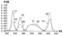
- the graph which shows the light-emission quantity of each LED required in order to obtain white light suitable for two endoscopes as an emitted light by taking a wavelength on a horizontal axis and taking a light-emission quantity on a vertical axis
- the graph which shows the light-emission amount of each LED required in order to obtain the illumination light suitable for two observation modes as an emitted light by taking a wavelength on a horizontal axis and taking a light-emission amount on a vertical axis
- 6 is a graph showing the relationship between ambient humidity and LED input power at a predetermined ambient temperature, with the horizontal axis representing the ambient humidity and the vertical axis representing the upper limit value of the input power to the LED.
- FIG. 1 is a block diagram showing a light source device according to the first embodiment of the present invention.
- the light source device is applied to an endoscope device having an endoscope, a video processor, and a monitor.
- the endoscope apparatus 1 includes an endoscope 10, a video processor 20, a monitor 30, and a light source device 40.
- the endoscope 10 has an elongated insertion portion 11 that can be inserted into a lumen or the like at the distal end side, and the proximal end side is detachably connected to the light source device 40 by a connector 12. ing.
- the endoscope 10 is detachably connected to the video processor 20 by a cable 17 and a connector 18.
- a cable 17 and a connector 18 can be attached to the light source device 40 and the video processor 20.
- an imaging element 13 for capturing an image of a subject such as in a lumen and a lens 14 for irradiating the subject with light from the light source device 40 are disposed.
- the illumination light transmitted from the light source device 40 via the light guide 15 is irradiated to the subject by the lens 14.
- the imaging device 13 is configured by a CCD, a CMOS sensor, or the like, and return light from the subject is incident on the imaging surface of the imaging device 13, photoelectrically converts the incident subject optical image, and outputs an imaging output based on the accumulated charge. Output sequentially.
- the image sensor 13 operates when a drive signal including a synchronization signal is supplied from the video processor 20, and supplies an imaging output to the video processor 20 via the signal line 16.
- the video processor 20 performs predetermined signal processing on the supplied imaging output to generate a video signal that can be displayed on the monitor 30.
- a video signal from the video processor 20 is supplied to the monitor 30 via the cable 21. In this way, an endoscopic image based on the imaging output can be displayed on the display screen of the monitor 30.
- the video processor 20 can control the light source device 40 so that the brightness of the captured image becomes the target brightness.
- the video processor 20 outputs information on the ratio between the brightness information obtained from the captured image and the target brightness to the light source device 40 as brightness control information.
- the brightness control information is supplied to the control unit 41 of the light source device 40 via the cable 22, and the light source device 40 controls the amount of illumination light based on the brightness control information.
- the example which comprises the video processor 20 and the light source device 40 by a separate body is shown, you may integrate.
- information on the ratio between the brightness information obtained from the captured image and the target brightness may be acquired as brightness control information.
- the light source device 40 generates, for example, an LED (R-LED) 42 that generates red light, an LED (G-LED) 43 that generates green light, an LED (B-LED) 44 that generates blue light, and purple light.
- LEDs that generate four colors of light will be described, but the types of colors and the number of colors are not limited to those in this embodiment.
- an LED that generates light of a different color may be added to FIG. 1, and the solid-state light emitting element may be a laser light source instead of the LED.
- the solid-state light emitting element may be a laser light source instead of the LED.
- You may have two or more solid light emitting elements of each color, respectively.
- Lenses 42a to 45a are arranged on the optical axes of the emitted light from the LEDs 42 to 45, respectively. Each of the lenses 42a to 45a converts the light emitted from the LEDs 42 to 45 into substantially parallel light and emits the light. On the optical axis of the lens 45a that emits light from the V-LED 45, dichroic filters 47 to 49 constituting an optical path portion are arranged. The light from the B-LED 44 is also incident on the dichroic filter 47 through the lens 44a. In addition, light from the G-LED 43 is incident on the dichroic filter 48 via the lens 43a, and light from the R-LED 42 is also incident on the dichroic filter 49 via the lens 42a.
- the dichroic filter 47 reflects blue light from the B-LED 44 and transmits violet light from the V-LED 45.
- the dichroic filter 48 reflects the green light from the G-LED 43 and transmits the combined light of violet light and blue light from the dichroic filter 47.
- the dichroic filter 49 reflects the red light from the R-LED 42 and transmits the combined light of violet light, blue light, and green light from the dichroic filter 48.
- Each dichroic filter does not transmit / reflect all wavelengths of incident light, but transmits or reflects light of some wavelengths without transmitting / reflecting all wavelengths. May be.
- the purple light, blue light, green light, and red light of the LEDs 42 to 45 are synthesized by the dichroic filters 47 to 49.
- the combined light of each color light from the dichroic filter 49 enters the light guide 15 of the endoscope 10 via the lens 50. It is possible to change the arrangement order of the LEDs 42 to 45 by appropriately setting the characteristics of the dichroic filters 47 to 49. However, the arrangement of the LEDs 42 to 45 in the order of the wavelength band of the emitted light is better for the dichroic filter. Setting of characteristics is easy.
- the LEDs 42 to 45 are driven by the LED drive unit 46 and light up.
- the LED drive unit 46 is controlled by the control unit 41 to generate, for example, a PWM pulse drive signal for driving each LED.
- Each of the LEDs 42 to 45 emits light with a light emission amount corresponding to the duty ratio and current amount of the PWM pulse of each drive signal supplied from the LED drive unit 46.
- the control unit 41 outputs the dimming information including the above-described brightness control information for controlling the LEDs 42 to 45 and the light amount ratio control information described later to the LED driving unit 46, whereby the duty ratio and current of the PWM pulse are output.
- the light level of the LEDs 42 to 45 is controlled by controlling the level.
- the control unit 41 causes the LEDs 42 to 45 to emit light so that the combined light of the respective color lights incident on the light guide 15 from the dichroic filter 49 has a predetermined color and the LEDs 42 to 45 can maintain a predetermined color balance.
- the light amount ratio control information which is the information of the light amount ratio is generated.
- the light quantity ratio of each of the LEDs 42 to 45 needs to be determined by the spectral sensitivity characteristics and spectral transmission characteristics of the endoscope 10 to be used.
- the imaging device 13 provided in the endoscope 10 has a predetermined spectral sensitivity characteristic. Further, not only the imaging element but also the spectral transmission characteristics of the light guide 15 which is a light guide optical system are different for each endoscope 10 to be used. In consideration of such spectral sensitivity characteristics and spectral transmission characteristics, the endoscope 10 is provided with a storage unit 19 that stores light amount ratio control information that is information relating to the ratio of light emission amounts (light amount ratios) of the LEDs. Yes. By causing each LED to emit light with the light emission amount based on the light amount ratio control information, the illumination light from the light source device 40 can be set to a color balance suitable for the endoscope 10.
- the driving of each LED is controlled based on the brightness control information so that the brightness of the captured image becomes the target brightness.
- FIG. 2 is a graph showing the light emission amount of each LED necessary for obtaining white light suitable for two endoscopes as emitted light, with the wavelength on the horizontal axis and the light emission amount on the vertical axis.
- a solid line indicates a light emission amount related to a predetermined first endoscope, and V1, G1, B1, and R1 indicate light emission amounts of purple, green, blue, and red LEDs, respectively.
- the broken lines in FIG. 2 indicate the light emission amounts necessary for the predetermined second endoscope, and V2, G2, B2, and R2 indicate the light emission amounts of the purple, green, blue, and red LEDs, respectively.
- the light emission amount of each LED required to obtain white light suitable for the first and second endoscopes is different, for example, the light emission amount of a red or purple LED is different. Is big.
- FIG. 3 is a graph showing the light emission amount of each LED necessary for obtaining illumination light suitable for two observation modes as emitted light, with the wavelength on the horizontal axis and the light emission amount on the vertical axis.
- FIG. 3A shows the light emission amount in the normal light observation mode
- FIG. 3B shows the light emission amount in the narrow-band light observation mode.
- the light emission amounts of the LEDs necessary for obtaining illumination light suitable for the normal light observation mode and the narrow-band light observation mode are different, and the narrow-band observation is performed. In this case, only the purple and green LEDs of the four colors need to be emitted.
- the storage unit 19 is also configured to store information on the light amount ratio for each observation mode.
- the wavelength region of the G light incident on the light guide 15 of the endoscope 10 from the dichroic filter 49 is narrowed as indicated by Gx.
- a filter (not shown) may be inserted on the optical path of the G light.
- a simultaneous endoscope that performs normal light observation by irradiating white light
- a surface sequential type that generates color images from images obtained in a surface sequential manner by sequentially irradiating R, G, B illumination light
- the endoscope is used.
- the illumination light it is necessary to sequentially turn on, for example, R, G, and B LEDs.
- the illumination with the optimum color balance can be achieved even in the field sequential endoscope. It can be performed.
- the light source device 40 is provided with a reading unit 51, and the reading unit 51 acquires the information on the light amount ratio from the storage unit 19 by connecting the endoscope 10 to the light source device 40 through the connector 12, for example. Can be done.
- the reading unit 51 outputs the read light amount ratio information to the control unit 41.
- the control unit 41 determines the light emission amounts of the LEDs 42 to 45 based on the light amount ratio information, and controls the light emission amounts of the LEDs 42 to 45 so as to maintain the light amount ratio.
- the reading unit 51 has been described as being provided in the light source device 40, the reading unit 51 may be provided in the video processor 20, and the control unit 41 may acquire information from the video processor 20. In order to obtain an optimal color balance, information on the light amount ratio suitable for the endoscope 10 may be input to the control unit 41, and the storage unit 19 and the reading unit 51 are not necessarily provided. You may provide the memory which memorize
- the light source device 40 is provided with an operation panel 52, and the operation panel 52 can output a signal based on a user operation to the control unit 41. By using this operation panel 52, it is also possible to input information on the light amount ratio of the endoscope 10.
- the operation panel 52 is provided with a display unit (not shown) so that the current set value and the like can be displayed.
- an endoscope that does not hold information on such a light quantity ratio may be adopted as the endoscope 10.
- the control unit 41 cannot acquire information on the light amount ratio for obtaining an appropriate color balance, the light emission amount of each of the LEDs 42 to 45 is set so as to obtain a predetermined light amount ratio. You may make it control.
- the control unit 41 controls the light emission amount of each of the LEDs 42 to 45 while maintaining a light amount ratio with which an optimum color balance can be obtained based on the brightness control information from the video processor 20.
- dimming information corresponding to the light amount value of the G-LED 43 to be set according to the brightness control information is stored in the memory unit 57, and the control unit 41 uses the memory unit 57 based on the brightness control information.
- the dimming information for controlling the G-LED 43 can be acquired by reading the dimming information stored in.
- the control part 41 can obtain
- a Peltier element 56 which is a thermoelectric conversion element, is attached to the R-LED 42 for cooling.
- the R-LED 42 has a substrate (not shown) and a light emitting unit disposed on the substrate.
- a Peltier element 56 is disposed on the back side of the substrate.
- the Peltier element 56 is a cooling member that utilizes heat reception and heat dissipation caused by the current flowing through the pn junction, and cools the R-LED 42 by bringing the cooling surface of the Peltier element 56 into contact with the back surface of the substrate of the R-LED 42. It is supposed to be.
- the cooling capacity of the Peltier element 56 varies depending on the current value of the drive current flowing through the Peltier element 56.
- the Peltier drive unit 55 is controlled by the control unit 41 and controls the cooling of the R-LED 42 by controlling the current value of the drive current that flows through the Peltier element 56.
- the R-LED 42 has lower light emission efficiency than the other LEDs 43 to 45, requires a large amount of electric power to obtain a sufficient amount of light emission, and accordingly generates more heat than the other LEDs 43 to 45. For this reason, FIG. 1 shows an example in which the Peltier element 56 is arranged only in the R-LED 42, but a Peltier element may be provided in another LED.
- control unit 41 controls each LED 42 to 45 at a predetermined temperature while preventing power from being consumed unnecessarily by performing cooling control according to the amount of heat generated by each LED 42 to 45. It is designed to maintain the range.
- the memory unit 57 stores each LED obtained based on information on the luminous efficiency (heat generation amount) of each LED 42 to 45 and information on the cooling capacity of each cooling member that cools each LED.
- Information indicating each cooling characteristic (hereinafter referred to as cooling characteristic information) is stored.
- the control unit 41 obtains information (hereinafter referred to as cooling ratio information) indicating what ratio should be used for cooling each LED. Note that the control unit 41 may obtain the cooling ratio information by calculating the light amount ratio information and the cooling characteristic information.
- the cooling characteristic information is information unique to the light source device 40 and is known
- a table (hereinafter referred to as a cooling ratio table) indicating correspondence between the light amount ratio and the cooling ratio information in consideration of the cooling characteristic information is stored in the memory. It can also be stored in the unit 57. In this case, the control unit 41 can acquire the cooling ratio information by referring to the cooling ratio table based on the light amount ratio information.
- the control unit 41 Based on the brightness control information and the cooling ratio information, the control unit 41 obtains the cooling capacity required for each LED, and sets the cooling member such as the Peltier element 56 and each fan described later so that the cooling capacity can be obtained. The driving power for driving is obtained.
- the cooling characteristic information is stored in the memory unit 57, and the cooling ratio is calculated based on the light amount ratio information and the cooling characteristic information to obtain the power supplied to the cooling member.
- the information may be input from the outside without storing the information.
- the light amount control and the cooling control may be performed using information corresponding to these information or related information instead of the information on the light amount ratio and the cooling characteristic information itself.
- the information is related to the endoscope model number information related to the light quantity ratio information and the light quantity ratio information.
- the light amount control and the cooling control can be performed using information indicating which observation mode is used.
- the information related to the light quantity ratio includes information on the endoscope model number, information indicating which observation mode, etc. in addition to the information on the light quantity ratio and the information corresponding to the light quantity ratio.
- the control unit 41 can perform light amount control and cooling control using information related to the light amount ratio.
- the control unit 41 outputs a control signal to the Peltier drive unit 55 so as to give the Peltier element 56 drive power based on the cooling capacity required for the R-LED 42.
- the Peltier element 56 exhibits a desired cooling capacity by the driving current corresponding to the heat generation amount corresponding to the light emission amount of the R-LED 42.
- the amount of light emitted by each LED varies significantly depending on the type of endoscope connected, the observation mode, and the like.
- the cooling capacity of the cooling member corresponding to each LED is controlled for each LED according to the heat generation amount corresponding to the light emission amount of each LED, and the cooling capacity for each LED is controlled. Is not sufficient, or it is possible to prevent excessive cooling and appropriately suppress the temperature rise due to the light emission of each LED.
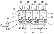
- FIG. 4 is an explanatory diagram for explaining an example of the cooling structure in the present embodiment.
- a cooling structure a method of providing a heat sink for each LED in order to dissipate heat from each LED, and arranging these heat sinks in a straight line from the intake port to the exhaust port can be considered.
- the air flowing in from the intake port is heated by receiving heat from each heat sink, and the heat sink closer to the exhaust port is less likely to dissipate heat. Therefore, it is conceivable to increase the size of the heat sink closer to the exhaust port.
- the size of the heat sink is limited by the distance from the air inlet by adopting a cooling structure in which air from the outside of the housing is similarly supplied to the heat sink corresponding to each LED. To prevent that.
- the cooling surface of the Peltier element 56 is in contact with the R-LED 42, and the heat dissipation surface of the Peltier element 56 is in contact with the heat receiving member 42b.
- Heat receiving members 43b to 45b are in direct contact with the other LEDs 43 to 45, respectively.
- One end of each heat pipe 42c to 45c is attached to each heat receiving member 42b to 45b, and the other end of each heat pipe 42c to 45c is attached to a heat sink 42d to 45d, respectively.
- the heat pipes 42c to 45c transmit the heat received by the heat receiving members 42b to 45b to the heat sinks 42d to 45d, respectively.
- a partition wall 61 that partitions the interior of the light source device 40 is provided between the heat sinks 42d to 45d and the heat receiving members 42b to 42b, and a heat radiation path 62 is formed on the heat sink side, and toward the LEDs 42 to 45 side. Inflow of heat is prevented.
- the heat dissipation path 62 is divided into heat dissipation paths for the respective LEDs 42 to 45 by a wall 65.
- An air inlet 63 is provided on one surface of the housing of the light source device 40 facing the partition wall 61, and between the air inlet 63 and the partition wall 61, heat sinks 42 d to 45 d corresponding to the LEDs 42 to 45. Is provided.
- Fans 42e to 45e are provided between the heat sinks 42d to 45d and the intake port 63, corresponding to the heat sinks 42d to 45d. With this configuration, air outside the housing can be directly passed through the heat sinks 42d to 45d corresponding to the LEDs 42 to 45 without passing through other heat sinks.
- the air flowing into the housing from the outside of the housing through the air inlet 63 by the fans 42e to 45e receives heat from the heat sinks 42d to 45d and flows to the partition wall 61 side. Further, the air received from the heat sinks 42d to 45d changes its direction according to the inclination of the partition wall 61, flows toward the exhaust port 64 provided on the other surface of the casing, and is discharged outside the casing.
- the heat transferred to the heat sinks 42d to 45d via the heat pipes 42c to 45c passes through a heat dissipation path (broken arrow) constituted by the air flow (arrow) flowing in from the intake port 63 and flowing out from the exhaust port 64, respectively. The heat is dissipated through.
- the cooling capacity is determined by the characteristics of the Peltier element 56, the heat pipes 42c to 45c, the heat sinks 42d to 45d, the fans 42e to 45e, and the like. For example, the cooling capacity varies depending on the sizes of the heat sinks 42d to 45d and the fans 42e to 45e. Further, the cooling capacity of the Peltier element 56 and the fans 42e to 45e varies depending on the magnitude of the driving power that is input.
- the memory unit 57 holds the cooling characteristic information in consideration of the cooling capacity and the like of these cooling members, and the control unit 41 calculates the cooling characteristic based on the light amount ratio information and the cooling characteristic information. In order to obtain a desired cooling capacity, the power supplied to the Peltier element 56 and the fans 42e to 45e can be calculated.
- the control unit 41 can acquire the cooling ratio information by referring to the cooling ratio table based on the information on the light amount ratio.
- a dust filter may be provided between the intake port 63 and the fans 42e to 45e.
- various members that change the aperture ratio of each of the fans 42e to 45e in the intake port 63 may be used.
- a punching metal or a slit-shaped member may be disposed in the intake port 63, and the opening ratio thereof may be changed for each position of the fans 42e to 45e.
- FIG. 5 is an explanatory view showing an example in which a punching metal or a slit-shaped member (hereinafter referred to as an inflow control member) is used in the vicinity of the intake port, and one fan is provided in the vicinity of the exhaust port.
- a heat dissipation path which is an air flow path is indicated by an arrow.
- the LEDs 42 to 45 are attached to the heat receiving members 42b to 45b, and the heat receiving members 42b to 45b are connected to the heat sinks 42h to 45h by the heat pipes 42c to 45c, respectively.
- Each of the heat sinks 42h to 45 is partitioned from each other by a wall 67 and arranged in an independent flow path.
- Inflow control members 42i to 45i are respectively arranged on the intake port side through which air flows to the heat sinks 42h to 45h.
- the light source device 40 is provided with a thermistor 53 in the vicinity of each of the LEDs 42 to 45.
- the thermistor 53 measures the temperature near each of the LEDs 42 to 45 and outputs the measurement result to the control unit 41.
- the light source device 40 is provided with a thermistor 54.
- the thermistor 54 is arranged at an appropriate position in the housing of the light source device 40, measures the temperature in the housing (room temperature), and the measurement result is sent to the control unit 41. Output to.
- FIG. 6 is a flowchart for explaining dimming control according to the first embodiment. Further, FIG. 7 is supplied to a fan and a Peltier element corresponding to each LED when two different endoscopes are used for the same observation mode and when the same endoscope is used for different observation modes. It is explanatory drawing for demonstrating electric power.
- the reading unit 51 reads out information on the light amount ratio stored in the storage unit 19 of the endoscope 10 and outputs the information to the control unit 41.
- the control part 41 acquires the information of the light quantity ratio for every endoscope and every observation mode (step S1). Further, the control unit 41 reads out the cooling ratio information by referring to the cooling ratio table stored in the memory unit 57 based on the information on the light amount ratio (step S2).
- the control unit 41 acquires brightness control information from the video processor 20 in step S3.
- the control unit 41 accesses the memory unit 57 based on the brightness control information, acquires a control value (current value or duty ratio) for controlling the G-LED 43 that is a reference LED, and controls the control value of the LED 43.
- a control value current value or duty ratio
- the control values of the other LEDs 42, 44, 45 are calculated with the light amount ratio based on the light amount ratio information.
- the control unit 41 generates dimming information for designating control values obtained for the LEDs 42 to 45 (step S4), and outputs them to the LED driving unit 46.
- step S5 the control unit 41 calculates the power to be supplied for each cooling member corresponding to each LED based on the light amount value of each LED 42 to 45 and the cooling ratio information read from the memory unit 57. To do.
- the LED drive unit 46 generates a PWM pulse having a duty ratio and a current value based on the dimming information, and supplies the PWM pulses to the LEDs 42 to 45 (step S6).
- the LEDs 42 to 45 generate a light amount of light based on the dimming information.
- Light emitted from the LEDs 42 to 45 is synthesized by the dichroic filters 47 to 49 and enters the light guide 15 through the lens 50 as illumination light.
- the illumination light transmitted through the light guide 15 is irradiated to the subject from the lens 14.
- control unit 41 controls the Peltier driving unit 55 so as to drive the Peltier element 56 with the calculated electric power.
- the Peltier drive part 55 gives the determined electric power to the Peltier device 56, and cools LED42 (step S7).
- control unit 41 controls the supply of power to the fans 42e to 45e so that the calculated power is supplied to the fans 42e to 45e corresponding to the LEDs 42 to 45, respectively.
- each of the fans 42e to 45e rotates with the power supply controlled individually.
- the flow rate of air that receives heat from the heat sinks 42d to 45d corresponding to the LEDs 42 to 45 is individually controlled, and cooling is controlled for each LED.
- the cooling members corresponding to the respective LEDs 42 to 45 are controlled in power based on the heat generation amount corresponding to the amount of light generated, thereby suppressing the temperature rise of each of the LEDs 42 to 45 and operating within a predetermined temperature range. enable.
- the cooling members corresponding to the LEDs 42 to 45 are individually controlled according to the amount of heat generated, and wasteful power consumption, noise, and the like can be prevented.
- the image sensor 13 receives reflected light from the subject and photoelectrically converts it to obtain a captured image.
- This captured image is supplied to the video processor 20 via the signal line 16.
- the video processor 20 performs predetermined signal processing on the captured image to generate a video signal, and supplies the video signal to the monitor 30 via the cable 21.
- the endoscopic image is displayed on the display screen of the monitor 30.
- the video processor 20 generates brightness control information by comparing the brightness of the captured image with the target brightness.
- the control unit 41 updates the dimming information based on the brightness control information. Thereafter, steps S3 to S7 are repeated to control the light amount according to the brightness based on the brightness control information, and to perform cooling control for each LED according to the heat generation amount corresponding to the light amount.
- appropriate cooling control can be performed for each LED even when the endoscope connected to the light source device 40 is switched or the observation mode is different in the same endoscope. is there.
- FIG. 7A shows power control to the cooling member for two different endoscopes in the same observation mode
- FIG. 7B shows the power control to the cooling member in different observation modes of the same endoscope. Power control is shown.
- the solid color indicates power control when a predetermined first endoscope is connected
- the hatched line indicates power control when a predetermined second endoscope is connected.
- FIG. 7A shows the electric power when obtaining illumination light having the same color balance and the same brightness in the first and second endoscopes.
- the electric power shown to Fig.7 (a) has shown the total electric power of the some cooling member corresponding to each LED. For example, the total power supplied to the fan and the Peltier element is shown for the R-LED, and the power supplied to the fan is shown for the other LEDs.
- the cooling capacity for each LED becomes uniform, indicating that the temperature of each LED can be maintained within a predetermined temperature range.
- 10 W, 20 W, 30 W, and 40 W are supplied to the cooling members corresponding to the V-LED, B-LED, G-LED, and R-LED of the first endoscope. This shows that the cooling capacity for each LED is made uniform.
- the cooling members corresponding to the V-LED, B-LED, G-LED, and R-LED When supplied, the cooling capacity for each LED becomes uniform, indicating that the temperature of each LED can be maintained within a predetermined temperature range.
- 20 W, 10 W, 20 W, and 60 W are supplied to the cooling members corresponding to the V-LED, B-LED, G-LED, and R-LED of the second endoscope. This shows that the cooling capacity for each LED is made uniform.
- FIG. 7B shows the power control to the cooling member for each LED in different observation modes of the same endoscope, the hatched lines indicate the power control in the normal light observation mode, and the plain is the narrow-band light observation mode.
- the power control at the time is shown.
- the electric power shown in FIG. 7B indicates the total electric power of a plurality of cooling members corresponding to each LED. For example, the total power supplied to the fan and the Peltier element is shown for the R-LED, and the power supplied to the fan is shown for the other LEDs.
- the cooling capacity for each LED becomes uniform, and the temperature of each LED can be maintained within a predetermined temperature range.
- the cooling capacity for each LED is made uniform.
- the cooling characteristic information and the light amount ratio information obtained based on the information on the heat generation amount corresponding to the light amount of each LED and the information on the cooling capacity of each cooling member that cools each LED. Based on the above, the cooling ratio of the cooling member corresponding to each LED is obtained, and the driving power of each cooling member is determined so as to obtain this cooling ratio. As a result, regardless of the amount of heat generated by each LED, each LED can be brought to a desired temperature, and it is possible to prevent power from being consumed unnecessarily and generating noise by rotating a fan unnecessarily. Can do.
- the correspondence between the amount of heat generated by each LED and the cooling capacity of the cooling member provided for each LED is constant regardless of the brightness of the illumination light, that is, the light quantity of each LED.
- the cooling ratio does not change
- the input power to the cooling member is linearly changed according to the amount of light of each LED.
- the correspondence between the amount of heat generated by each LED and the cooling capacity of the cooling member provided for each LED may change depending on the amount of light of each LED. Therefore, the input power to the cooling member may be changed while changing the cooling ratio stepwise or continuously in accordance with the light amount of each LED.
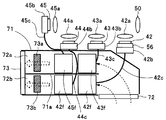
- FIG. 8 is an explanatory diagram for explaining another example of the cooling structure. In FIG. 8, the same components as those of FIG. 8.
- each LED 42 to 45 and the heat radiation path are partitioned by a partition wall 71 in the housing of the light source device. Furthermore, in the example of FIG. 8, the heat radiation path side is separated into two heat radiation paths 72a and 72b by a wall 71a. Heat sinks 43f and 45f are disposed on the heat radiation path 72a side, and heat sinks 42f and 44f are disposed on the heat radiation path 72b side. The heat sinks 42f to 45f are connected to the heat pipes 42c to 45c, respectively, so that heat generated by the LEDs 42 to 45 is transmitted.
- An air inlet 72 is provided on one end of one surface of the light source device facing the partition wall 71, and an air outlet 73 is provided on the other surface of the housing.
- the surface of the partition wall 71 facing the intake port 72 has an inclined surface that is inclined with respect to the air inflow direction, and directs the air flow toward the exhaust port 73.
- the inclined surface may be a curved surface.
- Fans 73a and 73b are respectively provided at the ends of the heat dissipation paths 72a and 72b in front of the exhaust port 73, and the air flowing in from the intake port 72 is forcibly forced by the rotation of the fans 73a and 73b. 72b can be discharged from the exhaust port 73.
- the heat radiation effect of the heat radiation paths 72a and 72b can be individually controlled. That is, as described above, the heat sinks 43f and 45f are arranged on the heat dissipation path 72a side, and the heat sinks 42f and 44f are arranged on the heat dissipation path 72b side. And the cooling capacity for the B-LED 44 and R-LED 42 groups can be individually controlled.
- the fans 73a and 73b are rotated during normal light observation, and the fan 73b is stopped and only the fan 73a is rotated during special light observation.
- the group of the V-LED 45 and the G-LED 43 that are lit needs to be cooled, and cooling control without waste is possible.
- the LEDs 42 to 45 can be individually controlled by controlling the heat radiating members other than the fans 73a and 73b.
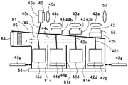
- FIG. 9 is an explanatory diagram for explaining another example of the cooling structure.
- the same components as those of FIG. 9 are identical.
- each LED 42 to 45 and the heat radiation path are partitioned by a partition wall 81 in the housing of the light source device.
- the heat radiation path of the cooling member for each LED is partitioned by the wall 81a.
- the fans 42e to 45e are provided between the heat sinks 42d to 45d and the intake port 63, respectively, but in the example of FIG. 9, these fans 42e to 45e are omitted and before the exhaust port 84.
- a single fan 85 is provided, and flow path restricting members 42g to 45g can be arranged between the heat sinks 42d to 45d and the intake port 83, respectively.
- the flow path restricting members 42g to 45g are driven so as to freely advance and retreat by a drive unit (not shown) so as to block a part of the air inlet 83.
- the control unit 41 controls a driving unit (not shown) to drive the flow path restricting members 42g to 45g forward and backward to control the flow rate of the heat radiation path.
- the flow path restricting members 42g to 45g arranged between the heat sinks 42d to 45d and the intake port 83 are individually removed, so that the intake port 83 to the exhaust port 84 can be removed at the removed position. Air flow is generated. Conversely, by individually disposing the flow path restricting members 42g to 45g between the heat sinks 42d to 45d and the intake port 83, it becomes difficult for air to flow from the intake port 83 to the exhaust port 84 at the disposed position.
- the heat radiation paths partitioned by the wall 81a are grouped into one heat radiation path 82 in the vicinity of the partition wall 81. If the rotation of the fan 85 is the same, some of the flow paths among the flow path restriction members 42g to 45g.
- the restricting member is disposed in the intake port 83, the air flow rate increases at a position where the flow restricting member is not disposed. Therefore, for example, when observing the special light, the flow restricting member is disposed so as to block the position corresponding to the LEDs 42 and 44 in the air inlet 83, so that the V is turned on without changing the rotation of the fan 85.
- the heat of the heat sinks 45d and 43d corresponding to the LED 45 and the G-LED 43 can be increased in the amount of air passing through the endotherm. For this reason, at the time of special light observation, the rotation speed of the fan 85 can be reduced compared with the case of normal light observation, and it is possible to reduce power consumption and noise caused by the fan.
- FIG. 10 is a flowchart employed in the second embodiment of the present invention.
- the hardware configuration of this embodiment is the same as that shown in FIG. In 1st Embodiment, the control part 41 calculated
- the light guide 15 used in the endoscope 10 is limited in the amount of light that can be incident / exited according to the type and diameter thereof.
- the amount of light emitted from the light source device 40 is limited to a predetermined maximum value (maximum light amount) or less for each endoscope or observation mode. It is necessary to That is, the amount of light emitted from each of the LEDs 42 to 45 needs to be set to a predetermined upper limit value or less, and therefore, the cooling capacity of the cooling member that cools each of the LEDs 42 to 45 needs to be limited.
- the storage unit 19 of the endoscope 10 stores such information regarding the maximum light amount, and the reading unit 51 reads out the information regarding the maximum light amount from the storage unit 19 and supplies the information to the control unit 41.
- the control unit 41 is configured to limit the maximum light amount of the emitted light from each of the LEDs 42 to 45 based on the information regarding the maximum light amount.
- the maximum amount of light emitted from the light source device 40 that is, the combined light of the LEDs 42 to 45 is limited, the light amount ratio of the LEDs 42 to 45 is determined. Can be requested. Therefore, information on the maximum light quantity allowed for a predetermined LED may be used as the information on the maximum light quantity.
- the storage unit 19 simply stores information on the endoscope model number and which observation mode it is in. Information to be shown may be stored. Information on the maximum light quantity includes information on the model number of such an endoscope, information indicating which observation mode is used, and the like.
- information on the maximum light amount suitable for the endoscope and the observation mode may be input to the control unit 41, and the storage unit 19 and the reading unit 51 are not necessarily provided.
- the operation panel 52 it is possible to input information on the maximum light amount.
- control unit 41 may control the light emission amounts of the LEDs 42 to 45 so that the light amount is equal to or smaller than a predetermined light amount.
- control unit 41 is given information on the maximum light amount, and determines the upper limit value (maximum cooling capacity) of the cooling capacity of the cooling member corresponding to each LED.
- the control part 41 calculates
- the control unit 41 acquires information on the maximum light amount in step S10 of FIG. In step S4, the control unit 41 obtains a control value for each LED and generates dimming information for designating the control value. In step S11, the control unit 41 determines whether or not the maximum light amount is exceeded when the control value obtained in step S4 is set in each of the LEDs 42 to 45. When the control values are set for the LEDs 42 to 45, the emitted light amounts of the LEDs 42 to 45 are known, and the control unit 41 obtains the emitted light amounts of the LEDs 42 to 45 and the combined light amount of the emitted lights by calculation. Can do.
- control unit 41 moves the process to step S12 and sets the control value to a value that can obtain a light amount equal to or less than the maximum light amount. Restrict. Thereby, the light quantity of the emitted light of the light source device 40 is limited to the maximum light quantity or less.
- the control unit 41 has been described as controlling so that the combined light of the light emitted from the LEDs 42 to 45 is less than or equal to the maximum light amount. However, since the light amount ratio of the LEDs 42 to 45 is defined, the control unit 41 is controlled. May be controlled so that the light quantity of any one or more of the LEDs 42 to 45 is less than or equal to the maximum light quantity allowed for the LED.
- the control unit 41 obtains the driving power of the cooling member for each LED in step S5.
- the controller 41 determines whether or not the cooling capacity for each LED exceeds the maximum cooling capacity when the driving power obtained in step S5 is set for each cooling member.
- the cooling capacity when driving power is set for the cooling members corresponding to the respective LEDs 42 to 45 is known, and the control unit 41 can obtain the cooling capacity of the cooling members corresponding to the LEDs 42 to 45 by calculation.
- the control unit 41 moves the process to step S14 and has a cooling capacity equal to or lower than the maximum cooling capacity. Limit to available values. As a result, the cooling capacity for the LEDs 42 to 45 is limited to the maximum cooling capacity or less, and the temperatures of the LEDs 42 to 45 are maintained within a predetermined temperature range.
- step S11 it may be determined whether or not the maximum light amount has been exceeded based on the actual measurement value of the optical sensor.
- the amount of light with respect to the control value varies due to variations in temperature characteristics of the LEDs. Therefore, by measuring the actual light amount by the optical sensor, it is possible to accurately obtain the light amount and enable high-precision control.
- step S13 it is determined whether or not the LED temperature has become equal to or lower than a predetermined lower limit value based on the actual measured value of the thermistor 53, and the power supplied to the cooling member is controlled in step S14. It may be.
- the LED temperature is actually measured to control the cooling capacity, and more accurate cooling control is possible.
- the light quantity and cooling capacity of the emitted light are limited according to the endoscope and the observation mode, so that the excessive light quantity is prevented and the excessive cooling capacity is exhibited. Can be prevented. Thereby, power consumption and noise can be suppressed.
- each of the LEDs 42 to 45 is driven with a light amount equal to or less than the maximum light amount.
- the input power of the LED is limited so that the junction temperature is within a predetermined threshold.
- the junction temperature has a correlation with the ambient temperature, and the higher the ambient temperature, the higher the junction temperature. Therefore, normally, an upper limit temperature is set as the ambient temperature, and an upper limit of power input to the LED is set based on the junction temperature at the set upper limit ambient temperature.
- FIG. 11 is a graph showing the relationship between the actual ambient temperature and the LED input power in this case, with the horizontal axis indicating the ambient temperature and the vertical axis indicating the upper limit value of the input power to the LED.
- the upper limit value of the maximum input power of the LED is defined on the assumption that the ambient temperature is the upper limit ambient temperature regardless of the actual ambient temperature. It becomes a constant value.
- the junction temperature also decreases, so there is no problem even if the input power to the LED is increased.
- the upper limit value of the maximum input power of the LED based on the ambient temperature, it is possible to increase the power that can be supplied to the LED and increase the amount of light.
- the thermistor 53 measures the temperature near the LEDs 42 to 45, and the thermistor 54 measures the ambient temperature.
- the controller 41 is given the temperature measurement result of the thermistors 53 and 54, and changes the upper limit value of the maximum input power of the LED based on the temperature measurement result.
- the thermistors 53 and 54 are preferably installed in places other than the heat dissipation path and where the emitted light from the LEDs 42 to 45 does not hit.
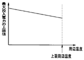
- FIG. 12 is a graph showing the relationship between the actual ambient temperature and the LED input power in this case, with the horizontal axis indicating the ambient temperature and the vertical axis indicating the upper limit value of the input power to the LED.
- the upper limit value of the maximum input power of the LED is defined in accordance with the actual ambient temperature. Therefore, the upper limit value of the maximum input power of the LED changes so as to increase as the ambient temperature decreases.
- the maximum value of the input power to the LED can be increased according to the ambient temperature, and the amount of light emitted from the LED can be increased.
- the LED needs to be used within a predetermined temperature range.
- the temperature increases as the input power increases. Therefore, by cooling the LED using a Peltier element or the like, the LED is used in a predetermined temperature range.
- the temperature of the cooling part becomes lower than the ambient temperature, and condensation may occur. Therefore, normally, in order to prevent the occurrence of condensation, the cooling capacity of the Peltier element is limited so that the cooling portion does not become lower than the ambient temperature. That is, even if a Peltier element is used, the upper limit value of the maximum input power of the LED needs to be set according to the upper limit ambient temperature assumed as the maximum value of the ambient temperature, and is a predetermined fixed value.
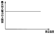
- FIG. 13 is a graph showing the LED input power in a predetermined ambient temperature environment, where the horizontal axis is the ambient humidity and the vertical axis is the upper limit value of the input power to the LED.
- humidity is not taken into consideration, and an upper limit value of the maximum input power of the LED is defined for a predetermined ambient temperature.
- the upper limit value of the maximum input power of the LED is a constant value. Although it is possible to change the upper limit of the maximum input power of the LED according to the ambient temperature by measuring the ambient temperature, in the case of the same ambient temperature, even if the humidity is relatively low, The upper limit value of the maximum input power of the LED is a constant value.
- the ambient temperature is measured by the thermistors 53 and 54, and the humidity (ambient humidity) in the vicinity of the Peltier element 56 is measured by a humidity sensor (not shown).
- the control unit 41 is given the measurement result of the thermistors 53 and 54 and the measurement result of the ambient humidity by the humidity sensor. Further, it is assumed that the memory unit 57 stores a look-up table of the saturated water vapor amount allowable for each ambient temperature. The control unit 41 obtains the moisture content at the measured ambient temperature and humidity by referring to the rookup table stored in the memory unit 57.
- the control unit 41 obtains a temperature that can be cooled by the Peltier element 56 without causing condensation by comparing the amount of water with the amount of saturated water vapor that is allowable for each ambient temperature.
- the control unit 41 determines the upper limit value of the maximum input power of the LED according to the coolable temperature.
- FIG. 14 is a graph showing the relationship between the ambient humidity and the LED input power at a predetermined ambient temperature, with the peripheral humidity on the horizontal axis and the upper limit value of the input power to the LED on the vertical axis.
- the cooling temperature by the Peltier element 56 is set according to the actual ambient humidity. Since the temperature can be set relatively low by the Peltier element 56, the upper limit of the maximum input power of the LED as the ambient humidity decreases. It changes as the value increases.
- the maximum value of the input power to the LED can be increased according to the ambient humidity, and the amount of light emitted from the LED can be increased.
- the LED is described as an example of the solid light emitting element, but a laser light source may be used.
- the present invention is not limited to the above-described embodiments as they are, and can be embodied by modifying the constituent elements without departing from the scope of the invention in the implementation stage.
- various inventions can be formed by appropriately combining a plurality of constituent elements disclosed in the above embodiments. For example, you may delete some components of all the components shown by embodiment.
- constituent elements over different embodiments may be appropriately combined.
Landscapes
- Health & Medical Sciences (AREA)
- Life Sciences & Earth Sciences (AREA)
- Surgery (AREA)
- Physics & Mathematics (AREA)
- Optics & Photonics (AREA)
- Engineering & Computer Science (AREA)
- Medical Informatics (AREA)
- General Health & Medical Sciences (AREA)
- Pathology (AREA)
- Nuclear Medicine, Radiotherapy & Molecular Imaging (AREA)
- Biomedical Technology (AREA)
- Heart & Thoracic Surgery (AREA)
- Biophysics (AREA)
- Molecular Biology (AREA)
- Animal Behavior & Ethology (AREA)
- Radiology & Medical Imaging (AREA)
- Public Health (AREA)
- Veterinary Medicine (AREA)
- General Physics & Mathematics (AREA)
- Signal Processing (AREA)
- Astronomy & Astrophysics (AREA)
- Microelectronics & Electronic Packaging (AREA)
- Endoscopes (AREA)
- Instruments For Viewing The Inside Of Hollow Bodies (AREA)
Abstract
Description
図1は本発明の第1の実施の形態に係る光源装置を示すブロック図である。本実施の形態は、光源装置を内視鏡、ビデオプロセッサ及びモニタを有する内視鏡装置に適用したものである。
図8は冷却構造の他の例を説明するための説明図である。図8において図4と同一の構成要素には同一符号を付して説明を省略する。
図10は本発明の第2の実施の形態に採用されるフローチャートである。図10において図6と同一の手順には同一符号を付して説明を省略する。本実施の形態のハードウェア構成は図1と同様である。第1の実施の形態においては、制御部41は、光量比に関する情報に基づいて冷却比率を求め、求めた冷却比率が得られるように、各LED毎の冷却部材への供給電力を制御した。しかし、内視鏡10に用いられているライトガイド15は、その種類や径に応じて、入出射可能な光量に制限がある。また、撮像素子13の撮像時にハレーションが生じないようにするためにも、内視鏡毎或いは観察モード毎に、光源装置40の出射光の光量は所定の最大値(最大光量)以下に制限される必要がある。即ち、各LED42~45の出射光の光量はそれぞれ所定の上限値以下に設定する必要があり、従って、これらのLED42~45をそれぞれ冷却する冷却部材の冷却能力も制限する必要がある。
本出願は、2013年10月30日に日本国に出願された特願2013-225778号を優先権主張の基礎として出願するものであり、上記の開示内容は、本願明細書、請求の範囲、図面に引用されたものとする。
Claims (12)
- 互いに異なる波長帯域の光を出射する複数の固体発光素子と、
前記複数の固体発光素子に対応して設けられて、前記各固体発光素子を冷却する複数の冷却手段と、
前記複数の固体発光素子の光量比に関連する情報が与えられて前記固体発光素子を個別に発光制御する発光素子制御部と、
前記光量比に対応した冷却比率に基づいて前記複数の冷却手段の冷却能力を制御して前記各固体発光素子を個別又はグループ毎に冷却制御する冷却制御部と
を具備したことを特徴とする光源装置。 - 前記冷却制御部は、前記光量比に関連する情報に基づいて前記冷却比率を求める
ことを特徴とする請求項1に記載の光源装置。 - 前記冷却制御部は、前記複数の冷却手段に供給する駆動電力を制御することで、前記複数の冷却手段の冷却能力を制御する
ことを特徴とする請求項1又は2に記載の光源装置。 - 前記複数の固体発光素子による照明光が供給される内視鏡の記憶部に記憶された前記光量比に関連する情報を読出す情報検知部
を具備したことを特徴とする請求項1乃至3のいずれか1に記載の光源装置。 - 前記発光素子制御部は、前記光量比に関連する情報が与えられない場合には、所定の光量比で前記固体発光素子を個別に発光制御し、
前記冷却制御部は、前記光量比に関連する情報が与えられない場合には、所定の冷却比率で前記複数の冷却手段の冷却能力を制御する
ことを特徴とする請求項1乃至4のいずれか1つに記載の光源装置。 - 前記光量比に関連する情報は、前記複数の固体発光素子による照明光が供給される内視鏡毎又は前記内視鏡の観察モード毎に設定される
ことを特徴とする請求項1乃至4のいずれか1つに記載の光源装置。 - 前記冷却手段は、前記冷却制御部により駆動が制御されるファン及び前記固体発光素子に設けられた冷却素子の少なくとも1つを含む
ことを特徴とする請求項1乃至6のいずれか1つに記載の光源装置。 - 前記複数の冷却手段の各々の放熱部に対しそれぞれ個別に冷却風を流入させる第1及び第2の吸気口を具備するとともに、
前記複数の冷却手段は、前記第1及び第2の吸気口の少なくとも一方に進退自在に設けられた流路制限部材を具備し、
前記冷却制御部は、前記流路制限部材の前記1及び/又は第2の吸気口への進退を制御する
ことを特徴とする請求項1乃至6のいずれか1つに記載の光源装置。 - 前記発光素子制御部は、前記固体発光素子がそれぞれ許容された所定の発光量以内で発光するように個別に発光制御し、
前記冷却制御部は、前記冷却手段がそれぞれ許容された冷却能力以内で冷却するように個別に冷却制御する
ことを特徴とする請求項1乃至8のいずれか1つに記載の光源装置。 - 周囲温度を検出する周囲温度検出部を具備し、
前記発光素子制御部は、前記複数の固体発光素子にそれぞれ投入可能な最大投入電力の上限値を前記周囲温度検出部が検出した周囲温度に基づいて設定する
ことを特徴とする請求項1乃至9のいずれか1つに記載の光源装置。 - 周囲温度を検出する周囲温度検出部と、
周囲湿度を検出する周囲湿度検出部とを具備し、
前記発光素子制御部は、前記複数の各固体発光素子にそれぞれ投入可能な最大投入電力の上限値を前記周囲温度検出部が検出した周囲温度及び前記周囲湿度検出部が検出した周囲湿度に基づいて設定する
ことを特徴とする請求項1乃至9のいずれか1つに記載の光源装置。 - 内視鏡と、
互いに異なる波長帯域の光を出射して前記内視鏡に照明光を供給する複数の固体発光素子と、
前記複数の固体発光素子に対応して設けられて、前記各固体発光素子を冷却する複数の冷却手段と、
前記複数の固体発光素子の光量比に関連する情報が与えられて前記固体発光素子を個別に発光制御する発光素子制御部と、
前記光量比に対応した冷却比率に基づいて前記複数の冷却手段の冷却能力を制御して前記各固体発光素子を個別又はグループ毎に冷却制御する冷却制御部と
を具備したことを特徴とする内視鏡装置。
Priority Applications (4)
| Application Number | Priority Date | Filing Date | Title |
|---|---|---|---|
| CN201480059084.4A CN105682536B (zh) | 2013-10-30 | 2014-10-23 | 光源装置和内窥镜装置 |
| EP14859050.8A EP3050492A4 (en) | 2013-10-30 | 2014-10-23 | Light source unit and endoscope device |
| JP2015525322A JP5927348B2 (ja) | 2013-10-30 | 2014-10-23 | 内視鏡装置 |
| US15/142,507 US10085630B2 (en) | 2013-10-30 | 2016-04-29 | Endoscope apparatus |
Applications Claiming Priority (2)
| Application Number | Priority Date | Filing Date | Title |
|---|---|---|---|
| JP2013225778 | 2013-10-30 | ||
| JP2013-225778 | 2013-10-30 |
Related Child Applications (1)
| Application Number | Title | Priority Date | Filing Date |
|---|---|---|---|
| US15/142,507 Continuation US10085630B2 (en) | 2013-10-30 | 2016-04-29 | Endoscope apparatus |
Publications (1)
| Publication Number | Publication Date |
|---|---|
| WO2015064470A1 true WO2015064470A1 (ja) | 2015-05-07 |
Family
ID=53004076
Family Applications (1)
| Application Number | Title | Priority Date | Filing Date |
|---|---|---|---|
| PCT/JP2014/078223 Ceased WO2015064470A1 (ja) | 2013-10-30 | 2014-10-23 | 光源装置及び内視鏡装置 |
Country Status (5)
| Country | Link |
|---|---|
| US (1) | US10085630B2 (ja) |
| EP (1) | EP3050492A4 (ja) |
| JP (1) | JP5927348B2 (ja) |
| CN (1) | CN105682536B (ja) |
| WO (1) | WO2015064470A1 (ja) |
Cited By (8)
| Publication number | Priority date | Publication date | Assignee | Title |
|---|---|---|---|---|
| WO2017104307A1 (ja) * | 2015-12-14 | 2017-06-22 | オリンパス株式会社 | 光源装置 |
| JPWO2016208015A1 (ja) * | 2015-06-24 | 2018-04-19 | オリンパス株式会社 | 光源装置と内視鏡装置 |
| DE112017002236T5 (de) | 2016-04-27 | 2019-01-17 | Olympus Corporation | Kühlvorrichtung und endoskop-lichtquellenvorrichtung |
| JP2019058689A (ja) * | 2018-11-20 | 2019-04-18 | 富士フイルム株式会社 | 内視鏡システム及び内視鏡システムの作動方法 |
| JP2019080624A (ja) * | 2017-10-27 | 2019-05-30 | ソニー・オリンパスメディカルソリューションズ株式会社 | 医療用光源装置及び医療用内視鏡装置 |
| JP2020116148A (ja) * | 2019-01-24 | 2020-08-06 | 富士フイルム株式会社 | 内視鏡システム |
| US11058290B2 (en) * | 2016-04-04 | 2021-07-13 | Olympus Corporation | Endoscope apparatus having a plurality of heat generators and corresponding air flow paths |
| JP2021162613A (ja) * | 2020-03-30 | 2021-10-11 | キヤノン株式会社 | 光源装置、照明装置、及び露光装置。 |
Families Citing this family (11)
| Publication number | Priority date | Publication date | Assignee | Title |
|---|---|---|---|---|
| EP3284391A1 (en) * | 2015-04-14 | 2018-02-21 | Olympus Corporation | Cooling device and endoscope light source device |
| WO2018011857A1 (ja) * | 2016-07-11 | 2018-01-18 | オリンパス株式会社 | 内視鏡装置 |
| JP7204530B2 (ja) * | 2019-02-28 | 2023-01-16 | キヤノン株式会社 | 照明装置およびその制御方法 |
| JP7150139B2 (ja) * | 2019-03-18 | 2022-10-07 | オリンパス株式会社 | 光源および内視鏡システム |
| DE102019114885B3 (de) | 2019-06-03 | 2020-08-13 | Karl Storz Se & Co. Kg | Vorrichtung zur Wärmeableitung aus einer endoskopischen Beleuchtungseinrichtung |
| CN110786817B (zh) * | 2019-11-13 | 2021-11-23 | 山西医科大学 | 一种基于led高效制冷的双波段光学分子影像光源装置 |
| TWI777147B (zh) * | 2020-03-27 | 2022-09-11 | 榮晶生物科技股份有限公司 | 內視鏡系統 |
| CN113448075A (zh) * | 2020-03-27 | 2021-09-28 | 荣晶生物科技股份有限公司 | 内视镜系统 |
| JP7587991B2 (ja) * | 2021-01-18 | 2024-11-21 | ソニー・オリンパスメディカルソリューションズ株式会社 | 医療用制御装置及び医療用観察システム |
| US20230314716A1 (en) * | 2022-03-29 | 2023-10-05 | Meta Platforms Technologies, Llc | Emission of particular wavelength bands utilizing directed wavelength emission components in a display system |
| DE102022133966A1 (de) * | 2022-12-19 | 2024-06-20 | Karl Storz Se & Co. Kg | Beleuchtungsvorrichtung, Bildgebungsvorrichtung und Verfahren zum Betrieb dieser |
Citations (6)
| Publication number | Priority date | Publication date | Assignee | Title |
|---|---|---|---|---|
| JPH08306226A (ja) * | 1995-04-28 | 1996-11-22 | Matsushita Electric Works Ltd | 調光装置 |
| JP2005257873A (ja) * | 2004-03-10 | 2005-09-22 | Seiko Epson Corp | プロジェクタ |
| JP2006162653A (ja) * | 2004-12-02 | 2006-06-22 | Olympus Corp | 光源装置及びプロジェクタ |
| JP2010256558A (ja) * | 2009-04-23 | 2010-11-11 | Sanyo Electric Co Ltd | 投写型映像表示装置 |
| JP2011036361A (ja) | 2009-08-10 | 2011-02-24 | Fujifilm Corp | 内視鏡装置 |
| JP2013225778A (ja) | 2012-04-20 | 2013-10-31 | Fujitsu Ltd | 通信装置および通信方法 |
Family Cites Families (27)
| Publication number | Priority date | Publication date | Assignee | Title |
|---|---|---|---|---|
| JPS5190831A (en) * | 1975-02-08 | 1976-08-09 | Ondo shitsudohogosochi | |
| DE2835331C3 (de) * | 1978-08-11 | 1981-11-05 | Siemens AG, 1000 Berlin und 8000 München | Endoskop mit elektrischer Bildübertragung |
| JPH0640174B2 (ja) * | 1988-07-20 | 1994-05-25 | 株式会社東芝 | 内視鏡装置 |
| US5076660A (en) * | 1990-01-26 | 1991-12-31 | Olympus Corporation | Light source receptacle for fiberoptic illumination |
| US6322496B1 (en) * | 1998-11-06 | 2001-11-27 | Asahi Kogaku Kogyo Kabushiki Kaisha | Electronic endoscope system |
| US6464633B1 (en) * | 1999-08-23 | 2002-10-15 | Olympus Optical Co., Ltd. | Light source device for endoscope using DMD |
| JP3583731B2 (ja) * | 2000-07-21 | 2004-11-04 | オリンパス株式会社 | 内視鏡装置および光源装置 |
| JP4321697B2 (ja) * | 2000-08-02 | 2009-08-26 | 富士フイルム株式会社 | 蛍光画像表示方法および装置 |
| JP4390096B2 (ja) * | 2001-07-06 | 2009-12-24 | 富士フイルム株式会社 | 内視鏡装置 |
| US7137696B2 (en) * | 2003-01-09 | 2006-11-21 | Con-Trol-Cure, Inc. | Ink jet UV curing |
| US7211299B2 (en) * | 2003-01-09 | 2007-05-01 | Con-Trol-Cure, Inc. | UV curing method and apparatus |
| EP1784696A2 (en) * | 2004-09-02 | 2007-05-16 | Liam Anthony Ryan | A control apparatus |
| EP3155998B1 (en) * | 2005-10-20 | 2021-03-31 | Intuitive Surgical Operations, Inc. | Auxiliary image display and manipulation on a computer display in a medical robotic system |
| US9351355B2 (en) * | 2005-12-30 | 2016-05-24 | Seoul Semiconductor Co., Ltd. | Illumination system having color temperature control and method for controlling the same |
| US7942548B2 (en) * | 2006-01-17 | 2011-05-17 | Mitsubishi Heavy Industries, Ltd. | Light-source lamp and projector |
| CN101689014B (zh) * | 2007-07-12 | 2011-09-21 | 松下电器产业株式会社 | 图像显示装置 |
| JP5081558B2 (ja) * | 2007-09-28 | 2012-11-28 | 三洋電機株式会社 | 投写型映像表示装置 |
| JP5460506B2 (ja) * | 2009-09-24 | 2014-04-02 | 富士フイルム株式会社 | 内視鏡装置の作動方法及び内視鏡装置 |
| US20110135170A1 (en) * | 2009-12-09 | 2011-06-09 | Capso Vision, Inc. | System and method for display speed control of capsule images |
| JP2011156339A (ja) * | 2010-01-08 | 2011-08-18 | Fujifilm Corp | 医療機器及び内視鏡装置 |
| JP5489748B2 (ja) * | 2010-01-27 | 2014-05-14 | 三菱電機株式会社 | 光源装置、投射型映像表示装置 |
| JP5345597B2 (ja) * | 2010-09-27 | 2013-11-20 | 富士フイルム株式会社 | 温度調節装置および温度調節方法、光源装置ならびに内視鏡診断装置 |
| EP2604178B8 (en) * | 2011-05-26 | 2016-11-09 | Olympus Corporation | Light source apparatus |
| WO2013031701A1 (ja) * | 2011-08-26 | 2013-03-07 | オリンパスメディカルシステムズ株式会社 | 内視鏡装置 |
| EP2769665A4 (en) * | 2012-05-01 | 2015-08-26 | Olympus Medical Systems Corp | Endoscope device |
| JP6120496B2 (ja) * | 2012-06-15 | 2017-04-26 | 三菱電機株式会社 | 光源装置 |
| US8622896B1 (en) * | 2013-01-04 | 2014-01-07 | Zafer Termanini | Liquid-cooled light source for endoscopy and irrigation/suction and power supply tubing and method thereof |
-
2014
- 2014-10-23 WO PCT/JP2014/078223 patent/WO2015064470A1/ja not_active Ceased
- 2014-10-23 JP JP2015525322A patent/JP5927348B2/ja not_active Expired - Fee Related
- 2014-10-23 CN CN201480059084.4A patent/CN105682536B/zh active Active
- 2014-10-23 EP EP14859050.8A patent/EP3050492A4/en not_active Withdrawn
-
2016
- 2016-04-29 US US15/142,507 patent/US10085630B2/en active Active
Patent Citations (6)
| Publication number | Priority date | Publication date | Assignee | Title |
|---|---|---|---|---|
| JPH08306226A (ja) * | 1995-04-28 | 1996-11-22 | Matsushita Electric Works Ltd | 調光装置 |
| JP2005257873A (ja) * | 2004-03-10 | 2005-09-22 | Seiko Epson Corp | プロジェクタ |
| JP2006162653A (ja) * | 2004-12-02 | 2006-06-22 | Olympus Corp | 光源装置及びプロジェクタ |
| JP2010256558A (ja) * | 2009-04-23 | 2010-11-11 | Sanyo Electric Co Ltd | 投写型映像表示装置 |
| JP2011036361A (ja) | 2009-08-10 | 2011-02-24 | Fujifilm Corp | 内視鏡装置 |
| JP2013225778A (ja) | 2012-04-20 | 2013-10-31 | Fujitsu Ltd | 通信装置および通信方法 |
Non-Patent Citations (1)
| Title |
|---|
| See also references of EP3050492A4 |
Cited By (14)
| Publication number | Priority date | Publication date | Assignee | Title |
|---|---|---|---|---|
| JPWO2016208015A1 (ja) * | 2015-06-24 | 2018-04-19 | オリンパス株式会社 | 光源装置と内視鏡装置 |
| JP6203467B1 (ja) * | 2015-12-14 | 2017-09-27 | オリンパス株式会社 | 光源装置 |
| WO2017104307A1 (ja) * | 2015-12-14 | 2017-06-22 | オリンパス株式会社 | 光源装置 |
| US10212780B2 (en) | 2015-12-14 | 2019-02-19 | Olympus Corporation | Light source device |
| US11058290B2 (en) * | 2016-04-04 | 2021-07-13 | Olympus Corporation | Endoscope apparatus having a plurality of heat generators and corresponding air flow paths |
| DE112017002236T5 (de) | 2016-04-27 | 2019-01-17 | Olympus Corporation | Kühlvorrichtung und endoskop-lichtquellenvorrichtung |
| US10617290B2 (en) | 2016-04-27 | 2020-04-14 | Olympus Corporation | Light source apparatus for endoscope having first second and third heat sinks for respective light sources and a first air flow through the first and third heat sinks and a merged air flow through the second heat sink |
| JP2019080624A (ja) * | 2017-10-27 | 2019-05-30 | ソニー・オリンパスメディカルソリューションズ株式会社 | 医療用光源装置及び医療用内視鏡装置 |
| JP2019058689A (ja) * | 2018-11-20 | 2019-04-18 | 富士フイルム株式会社 | 内視鏡システム及び内視鏡システムの作動方法 |
| JP2020116148A (ja) * | 2019-01-24 | 2020-08-06 | 富士フイルム株式会社 | 内視鏡システム |
| US11344191B2 (en) | 2019-01-24 | 2022-05-31 | Fujifilm Corporation | Endoscope system including processor for determining type of endoscope |
| JP7184657B2 (ja) | 2019-01-24 | 2022-12-06 | 富士フイルム株式会社 | 内視鏡システム |
| JP2021162613A (ja) * | 2020-03-30 | 2021-10-11 | キヤノン株式会社 | 光源装置、照明装置、及び露光装置。 |
| JP7458853B2 (ja) | 2020-03-30 | 2024-04-01 | キヤノン株式会社 | 光源装置、照明装置、及び露光装置。 |
Also Published As
| Publication number | Publication date |
|---|---|
| EP3050492A1 (en) | 2016-08-03 |
| CN105682536B (zh) | 2018-02-13 |
| CN105682536A (zh) | 2016-06-15 |
| US20160235285A1 (en) | 2016-08-18 |
| US10085630B2 (en) | 2018-10-02 |
| EP3050492A4 (en) | 2017-09-20 |
| JPWO2015064470A1 (ja) | 2017-03-09 |
| JP5927348B2 (ja) | 2016-06-01 |
Similar Documents
| Publication | Publication Date | Title |
|---|---|---|
| JP5927348B2 (ja) | 内視鏡装置 | |
| JP6329708B2 (ja) | 内視鏡用光源装置 | |
| CN109310277B (zh) | 医疗设备和医疗设备系统 | |
| JP6816138B2 (ja) | 内視鏡システム | |
| JP5245016B2 (ja) | 光源装置 | |
| JP6150944B2 (ja) | 撮像システム | |
| CN109104784B (zh) | 手术灯的光强补偿方法、装置、设备和计算机存储介质 | |
| US9526144B2 (en) | Light source apparatus and endoscope apparatus | |
| US20230420631A1 (en) | Light source device | |
| US10638923B2 (en) | Cooling unit and light source apparatus for endoscope | |
| US11320134B2 (en) | Cooling device, light source device, and medical observation system | |
| US10856730B2 (en) | Medical light source device and medical endoscopic device | |
| US10791595B2 (en) | Illuminating device | |
| JP7760467B2 (ja) | 電子内視鏡用プロセッサ | |
| WO2024024286A1 (ja) | 電子内視鏡用プロセッサ | |
| WO2014034205A1 (ja) | 光源装置 | |
| CN120659952A (zh) | 光源装置和冷却单元 |
Legal Events
| Date | Code | Title | Description |
|---|---|---|---|
| ENP | Entry into the national phase |
Ref document number: 2015525322 Country of ref document: JP Kind code of ref document: A |
|
| 121 | Ep: the epo has been informed by wipo that ep was designated in this application |
Ref document number: 14859050 Country of ref document: EP Kind code of ref document: A1 |
|
| REEP | Request for entry into the european phase |
Ref document number: 2014859050 Country of ref document: EP |
|
| WWE | Wipo information: entry into national phase |
Ref document number: 2014859050 Country of ref document: EP |
|
| NENP | Non-entry into the national phase |
Ref country code: DE |