WO2015064473A1 - 制御装置 - Google Patents
制御装置 Download PDFInfo
- Publication number
- WO2015064473A1 WO2015064473A1 PCT/JP2014/078240 JP2014078240W WO2015064473A1 WO 2015064473 A1 WO2015064473 A1 WO 2015064473A1 JP 2014078240 W JP2014078240 W JP 2014078240W WO 2015064473 A1 WO2015064473 A1 WO 2015064473A1
- Authority
- WO
- WIPO (PCT)
- Prior art keywords
- power
- power transmission
- state
- transmission
- receiving device
- Prior art date
- Legal status (The legal status is an assumption and is not a legal conclusion. Google has not performed a legal analysis and makes no representation as to the accuracy of the status listed.)
- Ceased
Links
Images









Classifications
-
- H—ELECTRICITY
- H02—GENERATION; CONVERSION OR DISTRIBUTION OF ELECTRIC POWER
- H02J—ELECTRIC POWER NETWORKS; CIRCUIT ARRANGEMENTS OR SYSTEMS FOR SUPPLYING OR DISTRIBUTING ELECTRIC POWER; SYSTEMS FOR STORING ELECTRIC ENERGY
- H02J50/00—Circuit arrangements or systems for wireless supply or distribution of electric power
- H02J50/80—Circuit arrangements or systems for wireless supply or distribution of electric power involving the exchange of data, concerning supply or distribution of electric power, between transmitting devices and receiving devices
-
- H—ELECTRICITY
- H02—GENERATION; CONVERSION OR DISTRIBUTION OF ELECTRIC POWER
- H02J—ELECTRIC POWER NETWORKS; CIRCUIT ARRANGEMENTS OR SYSTEMS FOR SUPPLYING OR DISTRIBUTING ELECTRIC POWER; SYSTEMS FOR STORING ELECTRIC ENERGY
- H02J50/00—Circuit arrangements or systems for wireless supply or distribution of electric power
- H02J50/10—Circuit arrangements or systems for wireless supply or distribution of electric power using inductive coupling
- H02J50/12—Circuit arrangements or systems for wireless supply or distribution of electric power using inductive coupling of the resonant type
-
- H—ELECTRICITY
- H02—GENERATION; CONVERSION OR DISTRIBUTION OF ELECTRIC POWER
- H02J—ELECTRIC POWER NETWORKS; CIRCUIT ARRANGEMENTS OR SYSTEMS FOR SUPPLYING OR DISTRIBUTING ELECTRIC POWER; SYSTEMS FOR STORING ELECTRIC ENERGY
- H02J50/00—Circuit arrangements or systems for wireless supply or distribution of electric power
- H02J50/40—Circuit arrangements or systems for wireless supply or distribution of electric power using two or more transmitting or receiving devices
-
- H—ELECTRICITY
- H02—GENERATION; CONVERSION OR DISTRIBUTION OF ELECTRIC POWER
- H02J—ELECTRIC POWER NETWORKS; CIRCUIT ARRANGEMENTS OR SYSTEMS FOR SUPPLYING OR DISTRIBUTING ELECTRIC POWER; SYSTEMS FOR STORING ELECTRIC ENERGY
- H02J50/00—Circuit arrangements or systems for wireless supply or distribution of electric power
- H02J50/70—Circuit arrangements or systems for wireless supply or distribution of electric power involving the reduction of electric, magnetic or electromagnetic leakage fields
-
- H—ELECTRICITY
- H02—GENERATION; CONVERSION OR DISTRIBUTION OF ELECTRIC POWER
- H02J—ELECTRIC POWER NETWORKS; CIRCUIT ARRANGEMENTS OR SYSTEMS FOR SUPPLYING OR DISTRIBUTING ELECTRIC POWER; SYSTEMS FOR STORING ELECTRIC ENERGY
- H02J50/00—Circuit arrangements or systems for wireless supply or distribution of electric power
- H02J50/90—Circuit arrangements or systems for wireless supply or distribution of electric power involving detection or optimisation of position, e.g. alignment
Definitions
- the present invention relates to a control device used in a power transmission system that transmits power from a power transmission device to a power reception device by a magnetic resonance method.
- the power transmission device does not grasp the power reception device existing around the power transmission device.
- the power transmission device does not grasp the power reception device in operation even if it grasps the power reception devices existing around the power transmission device.
- the power transmission apparatus cannot grasp the newly installed power receiving apparatus.
- the power transmission device transmits a search signal for searching for a power receiving device to be transmitted and detects the power receiving device to be transmitted based on information returned from the power receiving device.
- the power receiving device when the power receiving device does not have a power storage unit such as a capacitor or a secondary battery, the power receiving device cannot transmit information unless power is transmitted from the power transmitting device. In addition, even if the power receiving device has a power storage unit such as a capacitor or a secondary battery, if the power stored in the power storage unit cannot cover the power required for communication, the power must be transmitted from the power transmission device. In this case, the power receiving apparatus cannot transmit information.
- the control device is used in a power transmission system that transmits power from a power transmission device to a power reception device by a magnetic resonance method.
- the control device controls the transmission power of the power transmission device in a state where the power transmission target power receiving device is detected, and controls the power transmission power of the power transmission device in a state where the power transmission target power receiving device is not detected.
- a power control unit for controlling the test power transmission state is provided.
- the power control unit transitions to the test power transmission state in response to a predetermined trigger.
- the predetermined trigger is an event that activates the power transmission device, an event that the power transmission device is not transmitting power for a certain period, and an occurrence of at least one event of a user operation. It is.
- the power transmission method in the test power transmission state is different from the power transmission method in the power transmission state.
- the power control unit transitions from the test power transmission state to the power transmission state when the power receiving device to be transmitted is detected by power transmission in the test power transmission state.
- the power control unit transitions from the test power transmission state to the power transmission state when the power transmission target power receiving device is successfully authenticated after the power transmission target power receiving device is detected.
- the control device is used in a power transmission system that transmits power from a power transmission device to a power reception device by a magnetic resonance method.
- the control device is configured to control the transmission power of the power transmission device in a state where the power reception device as a power transmission target is detected, and to transmit the transmission power of the power transmission device in a state where preparation for power transmission to the power reception device as the power transmission target is ready.
- a power control unit that controls a standby state of waiting for
- the power control unit transitions from the power transmission state to the standby state in response to a predetermined trigger.
- the predetermined trigger is an occurrence of an event in which the power receiving device to be transmitted is not detected in the power transmission state.
- the power receiving device to be transmitted is an authenticated power receiving device.
- the power control unit controls transmission power of the power transmission device so as to transmit reference power in the power transmission state
- the predetermined trigger is configured such that the transmission power of the power transmission device is greater than the reference power. Is the occurrence of an event that falls below a small stop threshold.
- the power control unit controls transmission power of the power transmission device so as to transmit reference power in the power transmission state, and the power control unit transmits power of the power transmission device in the power transmission state.
- the resonance frequency of the power transmission device is adjusted.
- the predetermined trigger is occurrence of an event in which the transmission power of the power transmission device falls below a stop threshold value that is smaller than the adjustment threshold value.
- the predetermined trigger is an occurrence of an event in which a temperature of a component constituting the power transmission device exceeds a predetermined threshold in the power transmission state.
- the control device is used in a power transmission system that transmits power from a power transmission device to a power reception device by a magnetic resonance method.
- the control device is configured such that the power transmission device intermittently transmits power in a standby state where the power transmission device waits for power transmission in a state where power transmission preparation for the power transmission target power reception device is completed, and in a state where the power transmission target power reception device is not detected.
- the power control unit transitions from the standby state to the search power transmission state in response to a predetermined trigger.
- the predetermined trigger is an occurrence of an event in which the standby state continues for a certain period.
- the intermittent period in which the power transmission device transmits power is longer as the time in which the power transmission target power receiving device is not detected is longer.
- the power control unit controls a power transmission state for controlling the transmission power of the power transmission device in a state where the power receiving device to be transmitted is detected.
- the power control unit controls transmission power of the power transmission device so as to transmit reference power in the power transmission state.
- the power control unit controls transmission power of the power transmission device so as to transmit power smaller than the reference power in the search power transmission state.
- the control device is used in a power transmission system that transmits power from a power transmission device to a power reception device by a magnetic resonance method.
- the control device includes a power control unit that controls transmission power of the power transmission device based on at least one of the number of power reception devices to be transmitted and the type of the power reception device to be transmitted.
- the power receiving device to be transmitted is a power receiving device authenticated by the control device.
- the power control unit increases the transmission power of the power transmission device as the number of power receiving devices to be transmitted increases.
- the type of the power receiving device to be transmitted includes the received power of the power receiving device to be transmitted, whether the power receiving device has a power storage unit, or whether the power receiving device to be transmitted is It is specified by information indicating the capacity of the power storage unit.
- the power control unit controls the transmission power of the power transmission device so as to continuously transmit the transmission power when the power receiving device to be transmitted does not have a power storage unit.
- the power control unit controls transmission power of the power transmission device so that the transmission power is intermittently transmitted when the power receiving device to be transmitted has a power storage unit.
- the power control unit controls the transmission power of the power transmission device so as to intermittently transmit the transmission power
- the number of the power reception devices to be transmitted and the power transmission target The transmission interval of the transmitted power is controlled based on at least one of the types of power reception devices.
- the control device is used in a power transmission system that transmits power from a power transmission device to a power reception device by a magnetic resonance method.
- the control device includes: a resonance state in which the resonator of the power receiving device can resonate with the magnetic field generated from the power transmission device; and the non-resonance of the resonator of the power receiving device with respect to the magnetic field generated from the power transmission device.
- a resonance control unit is provided for controlling the state of the resonator of the power receiving device between the resonance state and the resonance state.
- the resonance control unit changes the state of the resonator of the power receiving device from the resonance state to the non-resonance state in response to a user operation.
- the power transmission system includes a first power receiving device and a second power receiving device as the power receiving device.
- the resonance control unit controls the resonance state and the non-resonance state of the first power receiving device.
- the resonance control unit changes the state of the resonator of the power receiving device from the resonance state to the non-resonant state according to the power receiving state of the second power receiving device.
- the power receiving device includes a power storage unit.
- the resonance control unit transitions the state of the resonator of the power receiving device from the non-resonance state to the resonance state when the amount of power stored in the power storage unit falls below a predetermined threshold.
- the control device is used in a power transmission system that transmits power from a power transmission device to a power reception device by a magnetic resonance method.
- the control device includes a power control unit that controls a first power transmission state in which power is transmitted with a first power amount and a second power transmission state in which power is transmitted with a second power amount larger than the first power amount.
- the power control unit controls transmission power of the power transmission device so as to transmit power with the first power in the first power transmission state.
- the power control unit controls transmission power of the power transmission device so that power is transmitted with a second power larger than the first power in the second power transmission state.
- the power control unit controls power transmission of the power transmission device so that power is intermittently transmitted at a first frequency in the first power transmission state.
- the power control unit controls power transmission of the power transmission device so that power is intermittently transmitted at a second frequency higher than the first frequency in the second power transmission state.
- the power control unit transitions to the second power transmission state when there are more power receiving devices to be transmitted.
- the power control unit transits to the second power transmission state when a power receiving device having an application whose power consumption fluctuation amount is greater than a predetermined value is included as a power receiving device.
- the power control unit when the power control unit receives a request to execute an application with high power consumption from the power receiving target power receiving device, or from the power transmitting target power receiving device to the high load state.
- the state transits to the second power transmission state.
- a control device is a control device used in a power transmission system that transmits power from a first device to a second device by a magnetic resonance method.
- the control device includes a control unit that acquires a power transmission voltage of the first device or a power reception voltage of the second device.
- the control unit when the acquired power transmission voltage exceeds a power transmission voltage threshold corresponding to the maximum power transmission efficiency of the first device, or when the acquired power reception voltage is the first device and the first When the power reception voltage threshold value corresponding to the allowable maximum distance between the two devices is below, the power transmission of the first device is stopped.
- the allowable maximum distance and the maximum power transmission efficiency are determined according to a function setting of the first device.
- the setting of the function is a setting related to an output setting of power transmission.
- the control unit when the first device transmits a communication signal and the second device receives the communication signal, the control unit causes the second device to start from the first device. Further acquiring the received signal strength of the received signal, the control unit, the acquired received voltage is less than the received voltage corresponding to the allowable maximum distance, and the acquired received signal strength is the allowable maximum distance When the received signal strength is lower than that of the first device, the power transmission of the first device is stopped.
- control unit sets a transmission voltage during initial power transmission of the first device as the transmission voltage threshold, and the transmission voltage during initial power transmission of the first device is power transmission. This is a power transmission voltage when power transmission is performed in a state where the target second device is not detected.
- the said control part further acquires the received signal strength of the signal which the said 2nd apparatus received from the said 1st apparatus,
- the said acquired power transmission voltage is the said power transmission voltage threshold value. And when the acquired received signal strength falls below the received signal strength when the first device transmits power at the maximum power transmission efficiency, the power transmission of the first device is stopped.
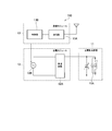
- FIG. 1 is a diagram illustrating a power transmission system 100 according to the first embodiment.
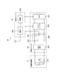
- FIG. 2 is a diagram illustrating the power transmission device 10 according to the first embodiment.
- FIG. 3 is a diagram illustrating the power receiving device 20 according to the first embodiment.
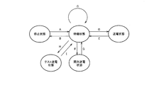
- FIG. 4 is a diagram illustrating state transition of the power transmission device 10 according to the first embodiment.
- FIG. 5 is a diagram for explaining types of the power receiving device 20 according to the first embodiment.
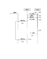
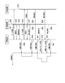
- FIG. 6 is a sequence diagram illustrating the power transmission method according to the first embodiment.
- FIG. 7 is a sequence diagram illustrating the power transmission method according to the first embodiment.
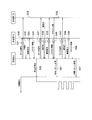
- FIG. 8 is a sequence diagram illustrating the power transmission method according to the first embodiment.
- FIG. 9 is a diagram for explaining the trigger E according to the second embodiment.
- FIG. 10 is a diagram illustrating state transition of the power transmission device 10 according to the third embodiment.
- FIG. 11 is a sequence diagram illustrating a power transmission method according to a modification of the fourth embodiment.
- FIG. 12 is a diagram for explaining a power transmission method according to a modified example of the fourth embodiment.
- FIG. 13 is a diagram illustrating state transition of the power transmission device 10 according to the sixth embodiment.
- FIG. 14 is a diagram illustrating a state transition of the power receiving device 20 according to the modified example of the sixth embodiment.
- FIG. 15 is a diagram illustrating a power transmission system 100 according to the seventh embodiment.
- FIG. 16 is a diagram illustrating a power transmission device 10 according to the seventh embodiment.
- FIG. 17 is a diagram illustrating a power receiving device 20 according to the seventh embodiment.
- FIG. 18 is a diagram illustrating an application scene of the power transmission system 100 according to the seventh embodiment.
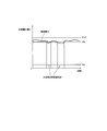
- FIG. 19A is a diagram illustrating a relationship between the power transmission distance and the power transmission efficiency according to the seventh embodiment.
- FIG. 19B is a diagram illustrating a relationship between the power transmission distance, the transmission power of the power transmission device 10, and the power reception voltage of the power reception device 20.
- FIG. 20 is a flowchart showing a control method according to the seventh embodiment.
- FIG. 21 is a flowchart showing a control method according to a modified example of the seventh embodiment.
- the control device is used in a power transmission system that transmits power from a power transmission device to a power reception device using a magnetic resonance method.
- the control device controls the transmission power of the power transmission device in a state where the power transmission target power receiving device is detected, and controls the power transmission power of the power transmission device in a state where the power transmission target power receiving device is not detected.
- a power control unit for controlling the test power transmission state is provided.
- the power receiving device to be transmitted can be detected without depending on the power state of the power receiving device.
- FIG. 1 is a diagram illustrating a power transmission system 100 according to the first embodiment.
- FIG. 2 is a diagram illustrating the power transmission device 10 according to the first embodiment.
- FIG. 3 is a diagram illustrating the power receiving device 20 according to the first embodiment.
- a power transmission system 100 includes a power transmission device 10 and a power reception device 20, and transmits power from the power transmission device 10 to the power reception device 20 using a magnetic field resonance method.
- a power receiving device 20 is illustrated, but a plurality of power receiving devices 20 may be provided in the power transmission system 100.
- the power receiving device 20 includes, for example, sensors (human sensor, temperature sensor, illuminance sensor) provided at each position in the room, and operates with electric power received from the power transmitting device 10.
- the power transmission device 10 is embedded, for example, in a room ceiling or under the floor in order to supply power to each sensor.
- the power transmission system 100 is not particularly limited, but may include an EMS (Energy Management System) for controlling the power of the consumer.
- EMS includes HEMS (Home Energy Management System), BEMS (Building Energy Management System) established in the building, FEMS (Factor Energy Management System established in the factory, and Management System EMS). It is done.
- the power transmission device 10 includes a power transmission side resonator 11, a power transmission module 12, and a communication module 13.
- the power transmission side resonator 11 is a resonator adjusted to resonate at a specific frequency.
- the power transmission side resonator 11 includes a capacitor C and an inductance L (coil).
- L coil
- the resonance frequency of the power transmission side resonator 11 can be adjusted to a specific frequency.
- the power transmission module 12 is a module that transmits electric power. Specifically, as illustrated in FIG. 2, the power transmission module 12 is directly connected to a commercial power source or connected to the commercial power source via an AC adapter.
- the power transmission module 12 when the power transmission module 12 is directly connected to a commercial power source, the power transmission module 12 includes a converter 12A and an inverter 12B.
- Converter 12A and inverter 12B generate AC power having a specific frequency.
- converter 12A converts AC power supplied from a commercial power source into DC power
- inverter 12B converts DC power output from converter 12A into AC power of a specific frequency.
- the power transmission module 12 when the power transmission module 12 is connected to a commercial power supply via an AC adapter, the power transmission module 12 has only the inverter 12B.
- the inverter 12B generates AC power having a specific frequency. In such a case, the inverter 12B converts the DC power output from the converter 12A into AC power having a specific frequency.
- the magnitude of the transmission power of the power transmission device 10 is determined by the magnitude of the AC power output from the inverter 12B.
- the communication module 13 is a module that communicates with the power receiving device 20.
- the communication module 13 may communicate with the EMS described above.
- the communication module 13 includes a communication unit 13A and a control unit 13B.
- the communication unit 13 ⁇ / b> A is connected to the power receiving device 20 wirelessly or in a wired manner, transmits a signal to the power receiving device 20, and receives a signal from the power receiving device 20. For example, as described later, the communication unit 13A transmits a search signal for searching for the power receiving device 20. The communication unit 13A transmits an information request for requesting transmission of information for specifying the type of the power receiving device 20. On the other hand, the communication unit 13 ⁇ / b> A receives the authentication ID of the power receiving device 20. The authentication ID is returned from the power receiving device 20 in response to the search signal. The communication unit 13A receives information for specifying the type of the power receiving device 20. Information for specifying the type of the power receiving device 20 is returned from the power receiving device 20 in response to the information request.
- the control unit 13B controls the power transmission module 12 and the communication module 13.
- the control unit 13B controls the transmission power of the power receiving device 20 in each state illustrated in FIG.
- the control unit 13B controls a power transmission state (a power transmission state and an intermittent power transmission state to be described later) for controlling the transmission power of the power transmission device 10 in a state where the power receiving device 20 to be transmitted is detected, and power transmission.
- a power control unit is configured to control a test power transmission state that controls transmission power of the power transmission device 10 in a state where the target power receiving device 20 is not detected.
- the control unit 13B controls the transmission power of the power transmission device 10 based on the information acquired by the communication unit 13A.
- the control unit 13B may be provided in the power transmission module 12 instead of being provided in the communication module 13.
- the control unit 13B may be provided in a control device different from the communication module 13 and the power transmission module 12, or the control device may control the communication module 13 and the power transmission module 12.
- the power receiving device 20 to be transmitted is preferably the power receiving device 20 authenticated by the power transmitting device 10 (control device). Therefore, it is preferable that the number of power receiving devices 20 to be transmitted is the number of power receiving devices 20 authenticated by the power transmitting device 10 (control device).
- control unit 13B controls the power transmission of the power transmission device 10 so as to continuously transmit power when the power receiving device 20 to be transmitted does not have a power storage unit.
- control unit 13B controls power transmission of the power transmission device 10 so that power is intermittently transmitted when the power receiving device 20 to be transmitted has a power storage unit.
- the control unit 13B may combine continuous power transmission and intermittent power transmission when the power receiving device 20 that does not have the power storage unit and the power receiving device 20 that has the power storage unit coexist.
- control the control unit 13B controls the power transmission of the power transmission device 10 so as to intermittently transmit power, based on at least one of the number of power reception devices 20 to be transmitted and the type of power reception device 20 to be transmitted, Control the transmission interval. For example, the control unit 13B shortens the power transmission interval as the number of power receiving devices 20 to be transmitted increases. Alternatively, the control unit 13B shortens the power transmission interval as the maximum received power of the power receiving device 20 to be transmitted is larger.
- the type of the power receiving device 20 to be transmitted includes the maximum received power of the power receiving device 20 to be transmitted, whether or not the power receiving device 20 has a power storage unit, or the capacity of the power storage unit of the power receiving device 20 to be transmitted. It is preferable to be specified by information indicating
- the received power means the power received by the power receiving apparatus from the power transmitting apparatus
- the maximum received power means the maximum power received by the power receiving apparatus from the power transmitting apparatus.
- the maximum received power of the power receiving device 20 that is a power transmission target is given as a parameter for specifying the type of the power receiving device 20, but the present invention is not limited thereto, and is necessary for the power receiving device 20 to execute predetermined control. It may be electric power, that is, necessary received electric power.
- control unit 13B increases the transmission power of the power transmission device 10 as the number of power reception devices 20 to be transmitted increases.
- the transmitted power means power transmitted from the power transmission device.
- control unit 13B increases the transmission power of the power transmission device 10 as the maximum received power of the power reception device 20 to be transmitted is larger.
- control unit 13B controls the transmission power of the power transmission device 10 so that power is continuously transmitted when the power receiving device 20 to be transmitted does not have the power storage unit.
- control unit 13B controls the transmission power of the power transmission device 10 so that power is intermittently transmitted when the power receiving device 20 to be transmitted has a power storage unit.
- the control unit 13B may combine continuous power transmission and intermittent power transmission when the power receiving device 20 that does not have the power storage unit and the power receiving device 20 that has the power storage unit coexist.
- control unit 13B controls the transmission power of the power transmission device 10 to transmit power intermittently
- the control unit 13B is based on the number of power reception devices 20 to be transmitted and the type of the power reception device 20 to be transmitted. Control the power transmission interval. For example, the control unit 13B shortens the power transmission interval as the number of power receiving devices 20 to be transmitted increases. Alternatively, the control unit 13B shortens the power transmission interval as the maximum received power of the power receiving device 20 to be transmitted is larger.
- the power receiving device 20 includes a power receiving side resonator 21, a power receiving module 22, and a communication module 23.
- the power receiving side resonator 21 is a resonator adjusted to resonate at a specific frequency.
- the power receiving resonator 21 includes a capacitor C and an inductance L (coil).
- the resonance frequency of the power receiving resonator 21 can be adjusted to a specific frequency by adjusting the capacitance of the capacitor C.
- the power receiving module 22 is a module that receives power. Specifically, as shown in FIG. 3, the power reception module 22 includes a rectifier circuit 22A, a DC / DC converter 22B, a load 22C, and a power storage unit 22D.
- the rectifier circuit 22A converts the DC power supplied from the power receiving resonator 21 into AC power.
- the DC / DC converter 22B performs step-up conversion or step-down conversion of the power supplied from the rectifier circuit 22A.
- the load 22C is transmitted by the power transmission device 10 and operates with the power supplied from the DC / DC converter 22B, and is, for example, the above-described sensors.
- the power storage unit 22D stores power that is transmitted by the power transmission device 10 and supplied from the rectifier circuit 22A.
- the power storage unit 22D is, for example, an electric double layer capacitor or a secondary battery.
- FIG. 3 illustrates a case where the power receiving module 22 includes the power storage unit 22D, but the embodiment is not limited to this. That is, the power receiving module 22 may not include the power storage unit 22D.
- the communication module 23 is a module that communicates with the power transmission device 10.
- the communication module 23 may communicate with the EMS described above. It should be noted that the communication module 23 operates with power received from the power transmission device 10.
- the communication module 23 includes a communication unit 23A and a control unit 23B.
- the communication unit 23 ⁇ / b> A is connected to the power transmission device 10 wirelessly or in a wired manner, transmits a signal to the power transmission device 10, and receives a signal from the power transmission device 10.
- the communication unit 23A receives a search signal for searching for the power receiving device 20.
- the communication unit 23A receives an information request for requesting transmission of information for specifying the type of the power receiving device 20.
- the communication unit 23A transmits the authentication ID of the power receiving device 20 in response to the search signal.
- the communication unit 23A transmits information for specifying the type of the power receiving device 20 in response to the information request.
- the control unit 23B controls the power receiving module 22 and the communication module 23.
- the control unit 23B supplies appropriate power to the load 22C under the control of the DC / DC converter 22B.
- the control unit 13B controls the load 22C according to an instruction received from the EMS.
- FIG. 4 is a diagram illustrating state transition of the power transmission device 10 according to the first embodiment.
- the state of the power transmission device 10 includes a stop state, a standby state, a power transmission state, an intermittent power transmission state, and a test power transmission state.
- the stop state is a state where power transmission is completely stopped. Specifically, the stop state is a state where the power transmission device 10 is not activated.
- the standby state is a state where power transmission is not performed but power transmission preparation is complete.
- the standby state is a state where the power receiving device 20 to be transmitted is not detected, and the power source of the power transmitting device 10 is activated.
- the power transmission state is a state in which power is continuously transmitted to the power receiving device 20 to be transmitted.
- the power transmission state is a state in which power is continuously transmitted, for example, when only the power receiving device 20 that is a power transmission target that does not have the power storage unit is detected.
- the power transmission state is a state in which the transmission power of the power transmission device 10 is controlled in a state where the power receiving device 20 to be transmitted is detected.
- the intermittent power transmission state is a state in which power is intermittently transmitted to the power receiving device 20 to be transmitted.
- the intermittent power transmission state is a state where power is intermittently transmitted, for example, when only the power receiving device 20 that is a power transmission target having the power storage unit is detected.
- the intermittent power transmission state is defined separately from the power transmission state, but the intermittent power transmission state may be considered as a part of the power transmission state.
- the intermittent power transmission state is a state in which the transmission power of the power transmission device 10 is controlled in a state where the power receiving device 20 to be transmitted is detected.
- the test power transmission state is a state in which power transmission is performed in a state where the power receiving device 20 to be transmitted is not detected. Specifically, in the test power transmission state, a signal (for example, the above-described authentication ID) can be returned from the power receiving device 20 by supplying power necessary for the communication module 23 of the power receiving device 20 to perform communication. In this state, power is transmitted.
- the test power transmission state is a state in which the transmission power of the power transmission device 10 is controlled in a state where the power receiving device 20 to be transmitted is not detected.
- the power transmission method in the test power transmission state may be different from the power transmission method in the power transmission state and the power transmission method in the intermittent power transmission state.
- the power transmission method in the test power transmission state is a method of repeating a power transmission section in which power transmission is performed and a non-power transmission section in which power transmission is not performed.
- the power transmission section in the test power transmission state is preferably longer than the power transmission section in the intermittent power transmission state.
- the power transmission method in the test power transmission state may be a method of continuously transmitting transmission power smaller than the transmission power in the power transmission state and the intermittent power transmission state.
- the trigger A that makes a transition from the stopped state to the standby state is, for example, an event that activates the power transmission device 10 (an event that turns on the power of the power transmission device 10).
- the trigger B that makes a transition from the standby state to the stop state is, for example, the occurrence of an event that turns off the power supply of the power transmission device 10.
- the trigger C for maintaining the standby state is an occurrence of an event in which the power receiving target power receiving device 20 is not detected.
- Trigger D that transitions from the standby state to the power transmission state is the occurrence of an event in which the power receiving device 20 that is a power transmission target that does not have a power storage unit is detected.
- the trigger E that makes a transition from the power transmission state to the standby state is an occurrence of an event in which all of the power receiving devices 20 that have been detected are not detected.
- the trigger E is generation
- Trigger F that makes a transition from the standby state to the intermittent power transmission state is the occurrence of an event in which the power receiving device 20 that is the power transmission target having the power storage unit is detected.
- the trigger G that makes a transition from the intermittent power transmission state to the standby state is an occurrence of an event in which all of the power receiving devices 20 that have been detected are not detected. Or the trigger G is generation
- Trigger H that transitions from the standby state to the test power transmission state is the occurrence of an event that transitions from the stopped state to the standby state. That is, the trigger H is an occurrence of an event for starting up the power transmission device 10 (an event of turning on the power of the power transmission device 10), as in the case of the trigger A. That is, when the power transmission device 10 is activated from the stopped state, the state transits to the standby state, and immediately after that, transits to the test power transmission state. In addition, you may transfer directly from the stop state to the test power transmission state without going through the standby state. Or the trigger H is generation
- the trigger H is a user operation.
- the trigger I that makes a transition from the test power transmission state to the standby state is an occurrence of an event in which the test power transmission state continues for a certain period.
- the trigger I is an occurrence of an event in which a response signal (for example, authentication ID, category information) to the search signal is received from the power receiving device 20.
- the trigger for transition from the test state to the power transmission state may be a case where the authentication ID is received from the power receiving device 20 and the category information is received after the authentication is successful or after the authentication is successful.
- “successful authentication” means, for example, that the received authentication ID matches the authentication ID stored in advance.
- FIG. 5 is a diagram for explaining types of the power receiving device 20 according to the first embodiment.
- the power receiving device 20 is classified into a plurality of categories (for example, categories 1 to 5). Each category is associated with an example of maximum received power and an application.
- the power receiving device 20 notifies the power transmitting device 10 of the category of the power receiving device 20 only by notifying the category of the power receiving device 20.
- the information for specifying the type of the power receiving device 20 may be information (category information) for identifying the category of the power receiving device 20.
- the type of the power receiving device 20 to be transmitted includes the maximum received power of the power receiving device 20 to be transmitted, whether the power receiving device 20 to be transmitted has a power storage unit, or whether the power receiving device 20 to be transmitted is It is preferable to be specified by information indicating the capacity of the power storage unit. Therefore, the category is preferably associated with these pieces of information.
- power transmission apparatus 10 detects a plurality of power reception apparatuses 20 and the maximum received power calculated from each category information exceeds the maximum transmission power, power transmission is stopped as an error.
- power transmission may be stopped as an error even when the power obtained by adding a predetermined value from the maximum received power exceeds the maximum transmitted power.
- power transmission may be performed with the maximum transmission power instead of stopping power transmission as an error.
- FIG. 6 to 8 are sequence diagrams showing the power transmission method according to the first embodiment.
- the power receiving device A is an example of the power receiving device 20.
- step S10 the power receiving apparatus A transitions to a signal reception standby state in order to start the operation of the load 22C.
- the signal reception standby state is a state in which reception of a signal transmitted from the power transmission device 10 is on standby.
- the power receiving apparatus A needs to hold power necessary for communication and be ready to communicate with the power transmission apparatus 10.
- the power transmission device 10 is in the test power transmission state, and the power necessary for communication is transmitted to the power receiving device A, and the power receiving device A is storing the transmitted power or the power receiving device A is transmitted. The power is continuously received.
- step S11 the power transmitting device 10 transmits a search signal for searching for the power receiving device 20.
- Step S11 is performed in the test power transmission state.
- step S12 the power receiving apparatus A transmits the authentication ID of the power receiving apparatus A to the power transmitting apparatus 10.
- the power transmitting device 10 authenticates the power receiving device A as the power receiving device 20 to be transmitted.
- step S13 the power transmission device 10 transmits to the power receiving device A an information request for requesting transmission of information for specifying the type of the power receiving device A.
- step S14 the power receiving apparatus A transmits information for identifying the type of the power receiving apparatus A to the power transmitting apparatus 10.
- the information for specifying the type of the power receiving apparatus A is category information for identifying the category shown in FIG.
- step S15 the power transmission device 10 starts power transmission according to the information (for example, category information) received in step S14.
- the electric power transmitted by the power transmission device 10 may be electric power according to information (for example, category information) received in step S14.
- the power transmitting device 10 controls power transmission so that power is continuously transmitted. That is, the power transmission device 10 transitions from the standby state to the power transmission state.
- step S16 the power receiving apparatus A cancels the signal reception standby state in order to stop the operation of the load 22C.
- step S ⁇ b> 17 the power transmission device 10 transmits a search signal for searching for the power reception device 20. Transmission of the search signal by the power transmission device 10 in step S17 is performed, for example, in a power transmission section in which power transmission is performed.
- step S18 the power transmission device 10 detects that a certain period has elapsed since the search signal was transmitted without a response to the search signal. In this case, the power transmitting apparatus 10 determines that the power receiving apparatus A has stopped receiving power and there is no other power receiving apparatus, and stops transmitting the transmitted power. That is, the power transmission device 10 transitions from the power transmission state to the standby state.
- the power receiving device B is an example of the power receiving device 20.
- step S20 the power receiving apparatus B transits to a signal reception standby state in order to start the operation of the load 22C.
- the power receiving apparatus B needs to hold power necessary for communication and be ready to communicate with the power transmission apparatus 10.
- the power transmission device 10 is in the test power transmission state, and power necessary for communication is transmitted to the power receiving device B.
- the power receiving apparatus B may cover power necessary for performing communication with the power stored in the power storage unit.
- step S21 the power transmission device 10 transmits a search signal for searching for the power reception device 20.
- the power transmission device 10 may be in a test power transmission state, for example.
- step S22 the power receiving apparatus B transmits the authentication ID of the power receiving apparatus B to the power transmitting apparatus 10.
- the power transmission device 10 authenticates the power reception device B as the power reception device 20 to be transmitted when the authentication ID stored in advance matches the authentication ID received from the power reception device B. It is assumed that this is successful in authentication.
- step S ⁇ b> 23 the power transmission device 10 transmits an information request for requesting transmission of information for specifying the type of the power reception device B to the power reception device B.
- step S24 the power receiving apparatus B transmits information for specifying the type of the power receiving apparatus B to the power transmitting apparatus 10.
- the information for specifying the type of the power receiving apparatus B is category information for identifying the category shown in FIG.
- step S25 the power transmission device 10 starts power transmission of the power transmission device 10 according to the information (for example, category information) received in step S24.
- the power transmitted by the power transmission device 10 may be power corresponding to information identifying the type of the power receiving device B received in step S24.
- the power transmitting device 10 starts power transmission of the power transmitting device 10 so as to transmit power intermittently. That is, the power transmission device 10 transitions from the standby state to the intermittent power transmission state.
- step S26 the power receiving apparatus B cancels the signal reception standby state in order to stop the operation of the load 22C.
- step S27 the power transmission device 10 transmits a search signal for searching for the power reception device 20.
- Transmission of the search signal by the power transmission device 10 in step S27 is performed, for example, in a power transmission section in which power transmission is performed.
- step S28 the power transmission device 10 detects that a certain period has elapsed since the search signal was transmitted without a response to the search signal.
- the power transmission device 10 stops power transmission. That is, the power transmission device 10 transitions from the intermittent power transmission state to the standby state.
- the power receiving device A and the power receiving device B are examples of the power receiving device 20.
- the operation shown in FIG. 8 is basically a combination of the operations shown in FIGS.
- step S30 the power receiving apparatus A transitions to a signal reception standby state in order to start the operation of the load 22C.
- the power receiving apparatus A needs to hold power necessary for communication and be ready to communicate with the power transmission apparatus 10.
- the power transmission device 10 is in a test power transmission state, and power necessary for communication is transmitted to the power receiving device A.
- step S31 the power transmission device 10 transmits a search signal for searching for the power reception device 20. Transmission of the search signal by the power transmission device 10 in step S31 is performed in the test power transmission state.
- step S32 the power receiving apparatus A transmits the authentication ID of the power receiving apparatus A to the power transmitting apparatus 10.
- the power transmitting device 10 authenticates the power receiving device A as the power receiving device 20 to be transmitted.
- the power receiving apparatus B since the power receiving apparatus B has not transitioned to the signal reception standby state, the power receiving apparatus B does not transmit the authentication ID.
- step S33 the power transmission device 10 transmits to the power receiving device A an information request for requesting transmission of information for specifying the type of the power receiving device A.
- step S ⁇ b> 34 the power receiving apparatus A transmits information for specifying the type of the power receiving apparatus A to the power transmitting apparatus 10.
- the information for specifying the type of the power receiving apparatus A is category information for identifying the category shown in FIG.
- step S35 the power transmission device 10 starts power transmission of the power transmission device 10 according to the information (for example, category information) received in step S34.
- the power transmitted by the power transmission device 10 may be power corresponding to information identifying the type of the power receiving device A received in step S34.
- the power transmission device 10 continuously transmits power to the power receiving device A.
- step S36 the power receiving apparatus B transitions to a signal reception standby state in order to start the operation of the load 22C.
- the power receiving apparatus B needs to hold power necessary for communication and be ready to communicate with the power transmission apparatus 10.
- the power transmission device 10 is in the test power transmission state, and power necessary for communication is transmitted to the power receiving device B.
- the power receiving apparatus B may cover power necessary for performing communication with the power stored in the power storage unit.
- step S37 the power transmission device 10 transmits a search signal for searching for the power reception device 20.
- step S38 the power receiving device A transmits the authentication ID of the power receiving device A to the power transmitting device 10.
- the power receiving apparatus B transmits the authentication ID of the power receiving apparatus B to the power transmitting apparatus 10.
- step S39 the power transmission device 10 transmits to the power receiving device A an information request for requesting transmission of information for specifying the type of the power receiving device A.
- the power transmission device 10 transmits an information request for requesting transmission of information for identifying the type of the power receiving device B to the power receiving device B.
- step S ⁇ b> 40 the power receiving apparatus A transmits information for specifying the type of the power receiving apparatus A to the power transmitting apparatus 10.
- the power receiving apparatus B transmits information for specifying the type of the power receiving apparatus B to the power transmitting apparatus 10.
- the information for specifying the types of the power receiving device A and the power receiving device B is category information for identifying the category shown in FIG.
- the transmission of the information request to the power receiving apparatus A in step S39 and the transmission of the category information from the power receiving apparatus A in step S40 may be omitted.
- step S41 the power transmission device 10 controls power transmission of the power transmission device 10 according to the information (for example, category information) received in step S40. That is, the power transmission device 10 changes the power transmission pattern.
- the power transmission device 10 transmits the power transmitted by the transmission power corresponding to the power receiving device A from the continuous power transmission at a constant transmission power, and the transmission power corresponding to the power reception device A for the power transmission power corresponding to the power reception device B.
- the power transmission pattern is changed so as to alternately repeat the state of transmitting the transmission power added to.
- the power receiving apparatus B is in a resonance state at the timing when the power transmitting apparatus 10 transmits the transmitted power corresponding to the power receiving apparatus B with the transmitted power added to the transmitted power corresponding to the power receiving apparatus A, and the power transmitting apparatus receives power. It may be in a non-resonant state at the timing of transmitting with the transmission power corresponding to the device A.
- the power transmission device 10 can perform appropriate power transmission according to the presence of the power reception device A and the power reception device B.
- step S42 the power receiving apparatus B cancels the signal reception standby state in order to stop the operation of the load 22C.
- step S43 the power transmission device 10 transmits a search signal for searching for the power reception device 20.
- step S44 the power receiving apparatus A transmits the authentication ID of the power receiving apparatus A to the power transmitting apparatus 10.
- the power transmitting device 10 authenticates the power receiving device A as the power receiving device 20 to be transmitted.
- the power receiving apparatus B since the power receiving apparatus B has not transitioned to the signal reception standby state, the power receiving apparatus B does not transmit the authentication ID.
- step S45 the power transmission device 10 transmits an information request for requesting transmission of information for specifying the type of the power reception device A to the power reception device A.
- step S ⁇ b> 46 the power receiving apparatus A transmits information for specifying the type of the power receiving apparatus A to the power transmitting apparatus 10.
- the information for specifying the type of the power receiving apparatus A is category information for identifying the category shown in FIG.
- step S47 the power transmission device 10 controls power transmission of the power transmission device 10 according to the information (for example, category information) received in step S46. That is, the power transmission device 10 changes the power transmission pattern.
- the power transmission device 10 intermittently transmits the transmission power corresponding to the power reception device B on the transmission power corresponding to the power reception device A while continuously transmitting the transmission power corresponding to the power reception device A.
- the power transmission pattern is changed so that the power is continuously transmitted with the transmitted power corresponding to the power receiving device A from the state where power is transmitted to the power receiving device A.
- the power receiving device 20 since the power transmission to the power receiving device 20 is performed by introducing the test power transmission state, the power receiving device 20 that is a power transmission target can be detected without depending on the power state of the power receiving device 20.
- the power transmission device 10 can receive the search signal by transmitting a search signal for searching for the power reception device 20 in the test power transmission state, and authenticate according to the search signal. ID can be transmitted. Accordingly, the power transmission device 10 can authenticate the power reception device 20 based on the authentication ID, and can detect the power reception device 20 to be transmitted.
- control device is used in a power transmission system that transmits power from a power transmission device to a power reception device by a magnetic resonance method.
- the control device is configured to control the transmission power of the power transmission device in a state where the power reception device as a power transmission target is detected, and to transmit the transmission power of the power transmission device in a state where preparation for power transmission to the power reception device as the power transmission target is ready.
- a power control unit that controls a standby state of waiting for The power control unit preferably transitions from the power transmission state to the standby state in response to a predetermined trigger.
- the power control unit transitions from the power transmission state to the standby state in response to a predetermined trigger.
- power can be appropriately transmitted to the power receiving apparatus by introducing the standby state.
- the control unit 13B controls a power transmission state (a power transmission state and an intermittent power transmission state to be described later) for controlling the transmission power of the power transmission device 10 in a state where the power receiving device 20 to be transmitted is detected.
- the power control unit that controls the test power transmission state that controls the transmission power of the power transmission device 10 in a state where the power receiving device 20 to be transmitted is not detected.
- control unit 13B controls the transmission power of the power transmission device 10 based on at least one of the number of power reception devices 20 to be transmitted and the type of power reception devices 20 to be transmitted.
- a power control unit is configured.
- the trigger E that makes a transition from the power transmission state to the standby state is an occurrence of an event in which all of the power receiving devices 20 that have been detected are not detected.
- the following method can be considered.
- the trigger E is an occurrence of an event in which a response signal (for example, an authentication ID) to the search signal cannot be received within a certain period after the search signal is transmitted. It should be noted that the search signal is transmitted periodically.
- a response signal for example, an authentication ID
- the power receiving device 20 to be transmitted is the authenticated power receiving device 20, and the authentication deadline of the power receiving device 20 expires when a certain period of time elapses after the authentication processing of the power receiving device 20 is performed. That is, the trigger E is an occurrence of an event in which all the authentication deadlines of the power receiving device 20 expire. It should be noted that the authentication process of the power receiving device 20 is performed periodically.
- the control unit 13B described above controls the transmission power of the power transmission device 10 to transmit power with the reference power (Wref) in the power transmission state, as shown in FIG.
- the trigger E is an occurrence of an event in which the transmission power of the power transmission device 10 falls below a stop threshold (Wer) that is smaller than the reference power (Wref).
- the power transmission device 10 periodically measures the transmission power of the power transmission device 10 in the power transmission state.
- the reference power (Wref) is acquired by measuring the transmission power of the power transmission device 10 in advance in a state where there is no power receiving device 20 to be transmitted.
- the reference power (Wref) is preferably associated in advance with at least one of the number of power receiving devices 20 to be transmitted and the type of power receiving devices 20 to be transmitted.
- the reference power (Wref) may be a fixed value.
- the stop threshold (Wer) is, for example, 10% of the reference power (Wref).
- the control unit 13B described above controls the transmission power of the power transmission device 10 so as to transmit the reference power (Wref) in the power transmission state, as shown in FIG.
- the control unit 13B adjusts the resonance frequency of the power transmission device 10 when the transmission power of the power transmission device 10 falls below the adjustment threshold (Wth) smaller than the reference power (Wref) in the power transmission state.
- the control unit 13B adjusts the resonance frequency of the power transmission side resonator 11 by adjusting the capacitance of the capacitor C so that the transmitted power of the power transmission device 10 exceeds the adjustment threshold value (Wth).
- the trigger E is an occurrence of an event in which the transmission power of the power transmission device 10 falls below a stop threshold (Wer) that is smaller than the adjustment threshold (Wth).
- the adjustment threshold (Wth) is, for example, 90% of the reference power (Wref).
- control unit 13B transitions from the power transmission state to the standby state in response to a predetermined trigger (trigger E described above).
- a predetermined trigger such as trigger E described above.
- the power transmission device does not grasp the power reception device existing around the power transmission device.
- the power transmission device does not grasp the power reception device in operation even if it grasps the power reception devices existing around the power transmission device.
- the power transmission apparatus cannot grasp the newly installed power receiving apparatus.
- the power transmission device transmits a search signal for searching for a power receiving device to be transmitted and detects the power receiving device to be transmitted based on information returned from the power receiving device.
- the power receiving device when the power receiving device does not have a power storage unit such as a capacitor or a secondary battery, the power receiving device cannot transmit information unless power is transmitted from the power transmitting device. In addition, even if the power receiving device has a power storage unit such as a capacitor or a secondary battery, if the power stored in the power storage unit cannot cover the power required for communication, the power must be transmitted from the power transmission device. In this case, the power receiving apparatus cannot transmit information.
- control device is used in a power transmission system that transmits power from the power transmission device to the power reception device by a magnetic resonance method.
- the control device is configured such that the power transmission device intermittently transmits power in a standby state where the power transmission device waits for power transmission in a state where power transmission preparation for the power transmission target power reception device is completed, and in a state where the power transmission target power reception device is not detected.
- the power receiving device to be transmitted can be detected without depending on the power state of the power receiving device.
- the control unit 13B controls a power transmission state (a power transmission state and an intermittent power transmission state to be described later) for controlling the transmission power of the power transmission device 10 in a state where the power receiving device 20 to be transmitted is detected.
- the power control unit that controls the test power transmission state that controls the transmission power of the power transmission device 10 in a state where the power receiving device 20 to be transmitted is not detected.
- control unit 13B controls the transmission power of the power transmission device 10 based on at least one of the number of power receiving devices 20 to be transmitted and the type of power receiving devices 20 to be transmitted.
- a power control unit is configured.
- FIG. 10 is a diagram illustrating state transition of the power transmission device 10 according to the third embodiment.
- the state of the power transmission device 10 includes a search power transmission state in addition to the states shown in FIG. 4 (stop state, standby state, power transmission state, intermittent power transmission state, test power transmission state).
- the search power transmission state is a state in which power transmission is performed in a state where the power receiving device 20 to be transmitted is not detected.
- a signal for example, the above-described authentication ID or the like
- the power transmission device 10 may transmit a search signal for searching for the power receiving device 20 by the communication unit 13A in the search power transmission state.
- the power receiving device 20 may start transmission of a search signal when a predetermined time has elapsed after transitioning to the search power transmission state and starting power transmission.
- the power transmission method in the search power transmission state may be different from the power transmission method in the power transmission state and the power transmission method in the intermittent power transmission state.
- the power transmission method in the search power transmission state is a method of repeating a power transmission section in which power transmission is performed and a non-power transmission section in which power transmission is not performed, similarly to the test power transmission state.
- the power transmission section in the search power transmission state is preferably longer than the power transmission section in the intermittent power transmission state.
- the longer the time in which the power receiving device 20 that is the target of power transmission is not detected is longer, the intermittent cycle in which the power transmitting device 10 transmits power in the search power transmission state (that is, the time between adjacent power transmission sections). It is preferable that the interval or the section length of the non-power transmission section is long.
- the power transmission section in the search power transmission state may be changed according to the time during which the state in which the power receiving device 20 to be transmitted is not detected continues.
- the control part 13B controls the transmitted power of the power transmission apparatus 10 so that it may transmit with reference
- the control unit 13B controls the transmission power of the power transmission device 10 so that the power is transmitted with power smaller than the reference power (for example, 40% of the reference power (Wref)). It is preferable to do.
- the control unit 13B may control the transmission power of the power transmission device 10 so that the reference power (Wref) used in the power transmission state immediately before the transition to the search power transmission state is transmitted in the search power transmission state.
- the reference power (Wref) may be the maximum transmitted power of the power transmission device 10. The maximum transmission power is the maximum power that can be transmitted by the power transmission device 10.
- Trigger J that transitions from the standby state to the search power transmission state is an occurrence of an event in which the standby state continues for a certain period.
- the trigger K that makes a transition from the search power transmission state to the standby state is an occurrence of an event in which the search power transmission state continues for a certain period.
- the trigger K is the occurrence of an event that receives a response signal (for example, authentication ID, category information) to the search signal from the power receiving device 20.
- the power transmission device 10 starts transmitting a search signal for searching for the power receiving device 20 when transitioning from the standby state to the search power transmission state, and transmits the search signal when transitioning from the search power transmission state to the standby state. You may stop.
- the search power transmission state is different from the standby state and the test power transmission state.
- the search power transmission state is not limited to this.
- the search power transmission state is a standby state or a test power transmission state. It is good also as being included in each state as one mode.
- the power receiving device 20 that is a power transmission target can be detected without depending on the power state of the power receiving device 20.
- control device is used in a power transmission system that transmits power from a power transmission device to a power reception device by a magnetic resonance method.
- the control device includes a power control unit that controls transmission power of the power transmission device based on at least one of the number of power reception devices to be transmitted and the type of the power reception device to be transmitted.
- the power receiving device to be transmitted is a power receiving device authenticated by the control device.
- the power control unit controls the transmission power of the power transmission device based on at least one of the number of power receiving devices to be transmitted and the type of power receiving device to be transmitted. Therefore, the transmission power of the power transmission device can be appropriately controlled in a usage scene in which power is transmitted wirelessly from one power transmission device to a plurality of power reception devices.
- the control unit 13B controls a power transmission state (a power transmission state and an intermittent power transmission state to be described later) for controlling the transmission power of the power transmission device 10 in a state where the power receiving device 20 to be transmitted is detected.
- the power control unit that controls the test power transmission state that controls the transmission power of the power transmission device 10 in a state where the power receiving device 20 to be transmitted is not detected.
- control unit 13B controls the transmission power of the power transmission device 10 based on at least one of the number of power reception devices 20 to be transmitted and the type of power reception devices 20 to be transmitted.
- a power control unit is configured.
- the control unit 13B of the power transmission device 10 controls the transmitted power of the power transmission device 10 based on at least one of the number of power reception devices 20 to be transmitted and the type of power reception devices 20 to be transmitted. Accordingly, the transmission power of the power transmission device 10 can be appropriately controlled in a usage scene where the power transmission device 10 wirelessly transmits power to the plurality of power reception devices 20.
- the power receiving device 20 has a function of transmitting a start request for requesting the start of power transmission and a stop request for requesting a stop of power transmission to the power transmission device 10.
- FIG. 11 is a sequence diagram illustrating a power transmission method according to the modified example.
- a case of transmitting power to the power receiving device C and the power receiving device D having the power storage unit is illustrated.
- a case where continuous power transmission is performed instead of intermittent power transmission for a power receiving device having a power storage unit will be described.
- step S50 the power receiving apparatus C transitions to a signal reception standby state in order to start the operation of the load 22C.
- the power receiving device C covers power necessary for communication with the power stored in the power storage unit.
- step S51 the power transmission device 10 transmits a search signal for searching for the power reception device 20.
- step S52 the power receiving apparatus C transmits the authentication ID of the power receiving apparatus C to the power transmitting apparatus 10.
- the power transmitting device 10 authenticates the power receiving device C as the power receiving device 20 to be transmitted.
- the power receiving apparatus D does not transmit the authentication ID because it has not transitioned to the standby state.
- step S53 the power receiving device C transmits a start request for requesting the start of power transmission to the power transmitting device 10.
- the start request preferably includes information indicating the received power desired by the power receiving apparatus C.
- step S54 the power transmission device 10 starts power transmission to the power reception device C in response to the start request received from the power reception device C.
- step S55 the power receiving device D transitions to a standby state in order to start the operation of the load 22C.
- the power receiving device D uses the power stored in the power storage unit to cover the power necessary for communication.
- step S56 the power transmission device 10 transmits a search signal for searching for the power reception device 20.
- step S57 the power receiving apparatus C transmits the authentication ID of the power receiving apparatus C to the power transmitting apparatus 10.
- the power receiving device D transmits the authentication ID of the power receiving device D to the power transmitting device 10.
- step S58 the power receiving device C transmits to the power transmitting device 10 a stop request for requesting to stop power transmission.
- step S59 the power transmission device 10 stops power transmission to the power reception device C in response to the stop request received from the power reception device C.
- step S60 the power receiving device D transmits a start request for requesting the start of power transmission to the power transmitting device 10.
- the start request preferably includes information indicating the received power desired by the power receiving device D.
- step S61 the power transmission device 10 starts power transmission to the power reception device D in response to the start request received from the power reception device D.
- step S62 the power receiving device C transmits a start request for requesting the start of power transmission to the power transmitting device 10.
- the start request preferably includes information indicating the received power desired by the power receiving apparatus C.
- step S63 the power transmission device 10 starts power transmission to the power reception device C in addition to power transmission to the power reception device D in response to a start request received from the power reception device C. That is, the power transmission device 10 transmits power by adding the power corresponding to the power receiving device C to the power corresponding to the power receiving device D.
- step S ⁇ b> 64 the power receiving device D transmits a stop request for requesting stop of power transmission to the power transmitting device 10.
- step S65 the power transmission device 10 stops power transmission to the power reception device D in response to the stop request received from the power reception device D. However, the power transmission device 10 continues power transmission to the power receiving device C.
- step S ⁇ b> 66 the power receiving device C transmits a stop request for requesting stop of power transmission to the power transmitting device 10.
- step S67 the power transmission device 10 stops power transmission to the power reception device C in response to the stop request received from the power reception device C.
- the power receiving device 20 monitors the power stored in the power storage unit 22D.
- the power receiving device 20 transmits a start request for requesting the start of power transmission to the power transmitting device 10 when the power stored in the power storage unit 22D falls below the first threshold.
- the power receiving device 20 transmits a stop request for requesting stop of power transmission to the power transmission device 10.
- the first threshold is a threshold at which charging of the power storage unit 22D should be started.
- the first threshold value is a capacitor charging start voltage.
- the second threshold value is a threshold value at which charging of the power storage unit 22D should be completed, and is a value larger than the first threshold value.
- the second threshold value is a capacitor charging end voltage.
- the power receiving device 20 preferably transitions from the non-resonant state to the resonant state when the power stored in the power storage unit 22D falls below a first threshold (for example, capacitor charging start voltage).
- the power receiving device 20 preferably transitions from the resonant state to the non-resonant state when the power stored in the power storage unit 22D exceeds a second threshold (for example, capacitor charging end voltage).
- the resonance state is a state that can resonate with the magnetic field generated from the power transmission device 10
- the non-resonance state is a state that cannot resonate with the magnetic field generated from the power transmission device 10.
- control device is used in a power transmission system that transmits power from a power transmission device to a power reception device by a magnetic resonance method.
- the control device includes: a resonance state in which the resonator of the power receiving device can resonate with the magnetic field generated from the power transmission device; and the non-resonance of the resonator of the power receiving device with respect to the magnetic field generated from the power transmission device.
- a resonance control unit is provided for controlling the state of the resonator of the power receiving device between the resonance state and the resonance state.
- whether or not the power receiving apparatus receives transmission power can be arbitrarily switched by introducing a resonance state and a non-resonance state.
- the control unit 13B controls a power transmission state (a power transmission state and an intermittent power transmission state to be described later) for controlling the transmission power of the power transmission device 10 in a state where the power receiving device 20 to be transmitted is detected.
- the power control unit that controls the test power transmission state that controls the transmission power of the power transmission device 10 in a state where the power receiving device 20 to be transmitted is not detected.
- control unit 13B controls the transmission power of the power transmission device 10 based on at least one of the number of power reception devices 20 to be transmitted and the type of power reception devices 20 to be transmitted. .
- the control unit 23B causes the resonance state in which the resonance frequency of the resonator of the power reception device 20 matches the resonance frequency of the resonator of the power transmission device 10 and the resonance frequency of the resonator of the power reception device 20 to transmit power.
- a resonance control unit that controls the state of the power-receiving-side resonator 21 is configured between a non-resonant state that does not match the resonance frequency of the resonator of the device 10.
- the resonance state is a state that can resonate with the magnetic field generated from the power transmission device 10
- the non-resonance state is a state that cannot resonate with the magnetic field generated from the power transmission device 10.
- the control unit 23B adjusts the resonance frequency of the power reception side resonator 21 by adjusting the capacitance of the capacitor C, and controls the state of the power reception side resonator 21 between the resonance state and the non-resonance state.
- control unit 23B may transition the state of the power receiving resonator 21 from the resonance state to the non-resonance state according to a user operation. Similarly, the control unit 23B may change the state of the power receiving resonator 21 from the non-resonance state to the resonance state in accordance with a user operation.
- the control unit 23B may control the resonance state of the power receiving resonator 21 in accordance with an instruction received from the EMS.
- the EMS manages the power receiving states of the plurality of power receiving devices 20, and instructs the state transition of the resonator of the first power receiving device according to the power receiving states of the second power receiving device.
- the EMS instructs the first power receiving device to transition from the resonance state to the non-resonance state when the power received by the second power receiving device falls below a predetermined threshold.
- EMS it is not restricted to EMS, Another control apparatus may be sufficient.
- control unit 23B may control the state of the resonator of the first power receiving device according to the power receiving state of the second power receiving device. For example, when the received power of the second power receiving device falls below a predetermined threshold, the control unit 23B causes the first power receiving device to transition the state of the power receiving resonator 21 from the resonance state to the non-resonance state.
- the control unit 23B may be configured separately from the first power receiving device.
- control unit 23B may control the state of the resonator of the power receiving device 20 according to the amount of power stored in the power storage unit 22D. For example, when the amount of power stored in the power storage unit 22D falls below a predetermined threshold, the control unit 23B changes the state of the power receiving resonator 21 from the non-resonance state to the resonance state.
- step S10 of FIG. 6 the power receiving apparatus A transitions from the non-resonant state to the resonant state when the current state is the non-resonant state.
- the power receiving device B transitions from the non-resonance state to the resonance state when the current state is the non-resonance state.
- step S26 of FIG. 7 the power receiving device B may transition from the resonance state to the non-resonance state.
- step S30 of FIG. 8 it should be noted that the power receiving apparatus A transitions from the non-resonance state to the resonance state when the current state is the non-resonance state.
- step S36 of FIG. 8 it should be noted that the power receiving apparatus B transitions from the non-resonant state to the resonance state when the current state is the non-resonant state.
- step S42 of FIG. 8 the power receiving apparatus B cancels the signal reception standby state in order to stop the operation of the load 22C.
- the power receiving device B may transition from the resonance state to the non-resonance state.
- whether or not the power receiving device 20 receives transmission power can be arbitrarily switched by introducing a resonance state and a non-resonance state.
- control device is used in a power transmission system that transmits power from a power transmission device to a power reception device by a magnetic resonance method.
- the control device includes a power control unit that controls a first power transmission state in which power is transmitted with a first power amount and a second power transmission state in which power is transmitted with a second power amount larger than the first power amount.
- the power control unit controls the transmission power amount in a stepwise manner in the first power transmission state and the second power transmission state, and therefore can appropriately and easily control the transmission power of the power transmission device.
- the control unit 13B controls a power transmission state (a power transmission state and an intermittent power transmission state to be described later) for controlling the transmission power of the power transmission device 10 in a state where the power receiving device 20 to be transmitted is detected.
- the power control unit that controls the test power transmission state that controls the transmission power of the power transmission device 10 in a state where the power receiving device 20 to be transmitted is not detected.
- control unit 13B controls the transmission power of the power transmission device 10 based on at least one of the number of power reception devices 20 to be transmitted and the type of power reception devices 20 to be transmitted.
- a power control unit is configured.
- the power receiving device 20 to be transmitted is preferably the power receiving device 20 authenticated by the power transmitting device 10 (control device). Therefore, it is preferable that the number of power receiving devices 20 to be transmitted is the number of power receiving devices 20 authenticated by the power transmitting device 10 (control device).
- FIG. 13 is a diagram illustrating state transition of the power transmission device 10 according to the sixth embodiment.
- the state of the power transmission device 10 includes a stopped state, a standby state, a first power transmission state, a first intermittent power transmission state, a test power transmission state, a second power transmission state, and a second intermittent power transmission state.
- the stop state is a state where power transmission is completely stopped. Specifically, the stop state is a state where the power transmission device 10 is not activated.
- the standby state is a state where power transmission is not performed but power transmission preparation is complete.
- the standby state is a state where the power receiving device 20 to be transmitted is not detected, and the power source of the power transmitting device 10 is activated.
- the first power transmission state is a state in which power is continuously transmitted to the power receiving device 20 to be transmitted with the first power.
- the first power transmission state is a state in which transmitted power is continuously transmitted, for example, when only the power receiving device 20 that is a power transmission target that does not have the power storage unit is detected.
- the first power transmission state is a first power transmission state in which power is transmitted with the first power amount as the transmitted power amount per unit time.
- the first intermittent power transmission state is a state where power is intermittently transmitted to the power receiving device 20 to be transmitted at the first frequency.
- the first intermittent power transmission state is a state in which power is intermittently transmitted at the first frequency when only the power receiving device 20 to be transmitted having the power storage unit is detected.
- the first intermittent power transmission state is defined separately from the first power transmission state, but the first intermittent power transmission state is a first power that is transmitted with the first power amount as the transmitted power amount per unit time. You may think that it is a part of the power transmission state.
- the test power transmission state is a state in which the transmission power is transmitted in a state where the power receiving device 20 to be transmitted is not detected.
- the test power transmission state is such that a signal (for example, the above-described authentication ID) can be returned from the power receiving device 20 by transmitting power necessary for the communication module 23 of the power receiving device 20 to perform communication. In this state, the transmitted power is transmitted.
- the power transmission method in the test power transmission state may be different from the power transmission method in the power transmission state and the power transmission method in the intermittent power transmission state.
- the power transmission method in the test power transmission state is a method of repeating a power transmission section in which power transmission is performed and a non-power transmission section in which power transmission is not performed.
- the power transmission section in the test power transmission state is preferably longer than the power transmission section in the intermittent power transmission state.
- the power transmission method in the test power transmission state may be a method of continuously transmitting transmission power smaller than the transmission power in the power transmission state and the intermittent power transmission state.
- the second power transmission state is a state in which power is continuously transmitted to the power receiving device 20 to be transmitted with a second power larger than the first power.
- the second power transmission state is a state in which power is continuously transmitted, for example, when only the power receiving device 20 that is a power transmission target that does not have the power storage unit is detected.
- the second power transmission state is a second power transmission state in which power is transmitted with a second power amount larger than the first power amount as the transmitted power amount per unit time.
- the second intermittent power transmission state is a state where power is intermittently transmitted to the power receiving device 20 to be transmitted at a second frequency higher than the first frequency.
- the second intermittent power transmission state is a state where power is intermittently transmitted at the second frequency, for example, when only the power receiving device 20 that is the power transmission target having the power storage unit is detected.
- the second intermittent power transmission state is defined separately from the second power transmission state, but the second intermittent power transmission state is a second higher than the first power amount as the transmission power amount per unit time. You may think that it is an aspect of the 2nd power transmission state which transmits electric energy.
- the trigger A that makes a transition from the stopped state to the standby state is, for example, an event that activates the power transmission device 10 (an event that turns on the power of the power transmission device 10).
- the trigger B that makes a transition from the standby state to the stop state is, for example, the occurrence of an event that turns off the power supply of the power transmission device 10.
- the trigger C for maintaining the standby state is an occurrence of an event in which the power receiving target power receiving device 20 is not detected.
- Trigger D that makes a transition from the standby state to the first power transmission state is the occurrence of an event in which the power receiving device 20 that is a power transmission target that does not have a power storage unit is detected.
- the condition of the trigger D is satisfied when, for example, the number of power receiving devices 20 to be transmitted is a predetermined number or less.
- the condition of the trigger D is satisfied when, for example, the power receiving device 20 having (using) the application (load) whose power consumption fluctuation amount is larger than a predetermined value is not included as the power receiving device 20 to be transmitted.
- the trigger E that makes a transition from the first power transmission state to the standby state is an occurrence of an event in which all of the power receiving devices 20 that have been detected are not detected.
- the trigger E is generation
- Trigger F that makes a transition from the standby state to the first intermittent power transmission state is the occurrence of an event in which the power receiving device 20 that is the power transmission target having the power storage unit is detected.
- the condition of the trigger F is satisfied when, for example, the number of power receiving devices 20 to be transmitted is a predetermined number or less.
- the condition of the trigger F is satisfied when, for example, the power receiving device 20 having (using) the application (load) whose power consumption fluctuation amount is larger than a predetermined value is not included as the power receiving device 20 to be transmitted.
- the trigger G that makes a transition from the first intermittent power transmission state to the standby state is an occurrence of an event in which all of the power reception target devices 20 that have been detected are not detected.
- the trigger G is generation
- Trigger H that transitions from the standby state to the test power transmission state is the occurrence of an event that transitions from the stopped state to the standby state. That is, the trigger H is an occurrence of an event for starting up the power transmission device 10 (an event of turning on the power of the power transmission device 10), as in the case of the trigger A. That is, when the power transmission device 10 is activated from the stopped state, the state transits to the standby state, and immediately after that, transits to the test power transmission state. In addition, you may transfer directly from the stop state to the test power transmission state without going through the standby state. Or the trigger H is generation
- the trigger H is a user operation.
- the trigger I that makes a transition from the test power transmission state to the standby state is an occurrence of an event in which the test power transmission state continues for a certain period.
- the trigger I is an occurrence of an event in which a response signal (for example, authentication ID, category information) to the search signal is received from the power receiving device 20.
- the trigger for transition from the test state to the power transmission state may be a case where the authentication ID is received from the power receiving device 20 and the category information is received after the authentication is successful or after the authentication is successful.
- “successful authentication” means, for example, that the received authentication ID matches the authentication ID stored in advance.
- the trigger J that makes a transition from the standby state to the second power transmission state is an occurrence of an event in which the power receiving device 20 that is a power transmission target that does not have a power storage unit is detected.
- the condition of the trigger J is satisfied, for example, when there are more power reception devices 20 to be transmitted.
- the condition of the trigger J is satisfied when, for example, the power receiving device 20 having an application whose power consumption fluctuation amount is larger than a predetermined value is included as the power receiving device 20 to be transmitted.
- the trigger K that makes a transition from the second power transmission state to the standby state is an occurrence of an event in which all of the power receiving devices 20 that have been detected are not detected.
- the trigger K is generation
- Trigger L that makes a transition from the standby state to the second intermittent power transmission state is the occurrence of an event in which the power receiving device 20 that is the power transmission target having the power storage unit is detected.
- the condition of the trigger L is satisfied when, for example, the power receiving devices 20 to be transmitted are larger than a predetermined number.
- the condition of the trigger L is satisfied when, for example, the power receiving device 20 having an application whose power consumption fluctuation amount is larger than a predetermined value is included as the power receiving device 20 to be transmitted.
- the trigger M that makes a transition from the second intermittent power transmission state to the standby state is an occurrence of an event in which all of the power receiving devices 20 that have been detected are not detected.
- the trigger M is generation
- FIG. 13 illustrates the state transition between the standby state and the second power transmission state, but the embodiment is not limited to this.
- the power transmission state of the power transmission device 10 may transition between a first power transmission state and a second power transmission state.
- the trigger for making a transition from the first power transmission state to the second power transmission state is that the power receiving device 20 having an application in which the power receiving devices 20 to be transmitted are larger than a predetermined number or the fluctuation amount of power consumption is larger than a predetermined value is transmitted by the power receiving device 20 This is an occurrence of an event included as the target power receiving apparatus 20.
- the trigger for transitioning from the second power transmission state to the first power transmission state is an event in which the number of power receiving devices 20 to be transmitted is equal to or less than a predetermined number, or a power receiving device having an application whose power consumption fluctuation amount is greater than a predetermined value The occurrence of an event 20 is not included as the power receiving device 20 to be transmitted.
- the state transition between the standby state and the second intermittent power transmission state is illustrated, but the embodiment is not limited to this.
- the intermittent power transmission state of the power transmission device 10 may transition between a first intermittent power transmission state and a second intermittent power transmission state.
- the trigger for making a transition from the first intermittent power transmission state to the second intermittent power transmission state is an event in which the power receiving devices 20 to be transmitted have a larger number than a predetermined number, or an application having a power consumption fluctuation amount larger than a predetermined value. Is the occurrence of an event included as the power receiving device 20 to be transmitted.
- the trigger for transitioning from the second intermittent power transmission state to the first intermittent power transmission state has an event in which the power receiving device 20 to be transmitted is equal to or less than a predetermined number, or an application whose power consumption fluctuation amount is larger than a predetermined value.
- the trigger N (or trigger P) that transitions from the first power transmission state (or the first intermittent power transmission state) to the second power transmission state (or the second intermittent power transmission state) is an application that consumes high power from the power receiving device 20.
- the trigger O (or trigger Q) that transitions from the second power transmission state (or the second intermittent power transmission state) to the first power transmission state (or the first intermittent power transmission state) is an application that consumes high power from the power receiving device 20.
- the power transmission state applied to the power receiving apparatus A may be the first power transmission state or the second power transmission state.
- the intermittent power transmission state applied to the power receiving apparatus B may be the first intermittent power transmission state or the second intermittent power transmission state.
- control part 13B since the control part 13B controls the transmitted power amount per unit time in steps in a 1st power transmission state and a 2nd power transmission state, it controls appropriately and simply the transmitted power of a power transmission apparatus. Can do.
- FIG. 14 is a diagram illustrating a state transition of the power receiving device 20 according to the modified example.
- the state of the power receiving device 20 includes a stopped state, a standby state, a first power receiving state, and a second power receiving state.
- the stop state is a state where power reception is completely stopped.
- the stopped state is a state in which the resonance frequency of the resonator of the power receiving device 20 does not match the resonance frequency of the resonator of the power transmission device 10, and this state is hereinafter also referred to as a non-resonant state.
- the non-resonant state is a state in which resonance with the magnetic field generated from the power transmission device 10 is impossible.
- the standby state is a state where power is not being received but preparation for power reception is complete.
- the standby state is a state in which the resonance frequency of the resonator of the power receiving device 20 matches the resonance frequency of the resonator of the power transmission device 10, and this state is hereinafter also referred to as a resonance state.
- the resonance state is a state in which resonance with the magnetic field generated from the power transmission device 10 is possible.
- the first power receiving state is a state in which power is received with power smaller than a predetermined threshold.
- the first power receiving state is a state in which an application (load 22C) with power consumption smaller than a predetermined threshold is driven.
- the power transmission device 10 operates in the first power transmission state (or the first intermittent power transmission state) described above.
- the first power receiving state is an example of the low load state described above.
- the second power receiving state is a state in which power is received with power larger than a predetermined threshold.
- the second power receiving state is a state in which an application (load 22C) with power consumption larger than a predetermined threshold is driven.
- the power transmission device 10 operates in the above-described second power transmission state (or second intermittent power transmission state).
- the second power receiving state is an example of the above-described high load state.
- the trigger X1 that makes a transition from the stopped state to the standby state is, for example, the occurrence of an event that activates the power receiving device 20.
- the trigger X1 may be a trigger that ends the power reception operation of the power reception device 20.
- the power receiving device 20 (the control unit 23B) adjusts the resonance frequency of the power receiving resonator 21 by adjusting the capacitance of the capacitor C according to the trigger X1, and transitions to the resonance state.
- the trigger X2 that makes a transition from the standby state to the stop state is, for example, the occurrence of an event that turns off the power supply of the power receiving device 20.
- the trigger X2 may be a trigger that starts the power receiving operation of the power receiving device 20.
- the power receiving device 20 (the control unit 23B) adjusts the resonance frequency of the power receiving resonator 21 by adjusting the capacitance of the capacitor C according to the trigger X2, and transitions to a non-resonant state. .
- the trigger Y1 that makes a transition from the standby state to the first power reception state is, for example, the occurrence of an event that starts an application (load 22C) that consumes less power than a predetermined threshold.
- the trigger Y2 that makes a transition from the first power receiving state to the standby state is, for example, the occurrence of an event that terminates an application (load 22C) that consumes less power than a predetermined threshold. It is preferable that the power receiving device 20 transmits to the power transmitting device 10 that the trigger Y1 or the trigger Y2 has been detected in response to the detection of the trigger Y1 or the trigger Y2.
- the trigger Z1 that makes a transition from the first power receiving state to the second power receiving state is, for example, the occurrence of an event that activates an application (load 22C) that consumes power that is greater than a predetermined threshold.
- the trigger Z2 that makes a transition from the second power receiving state to the first power receiving state is, for example, the occurrence of an event that ends an application (load 22C) that consumes power that is greater than a predetermined threshold. It is preferable that the power receiving device 20 transmits to the power transmitting device 10 that the trigger Z1 or the trigger Z2 has been detected in response to the detection of the trigger Z1 or the trigger Z2.
- the transition may be made directly to the second power receiving state without going through the first power receiving state.
- control device is used in a power transmission system that transmits power from a power transmission device to a power reception device by a magnetic resonance method.
- the control device includes a control unit that acquires a power transmission voltage of the power transmission device or a power reception voltage of the power reception device. When the acquired power transmission voltage exceeds a power transmission voltage threshold corresponding to the maximum power transmission efficiency of the power transmission device, or the acquired power reception voltage is between the power transmission device and the power reception device. The power transmission of the power transmission device is stopped when the received voltage threshold value corresponding to the permissible maximum distance is below.
- the control device stops power transmission of the power transmission device when the power transmission voltage exceeds the power transmission voltage threshold or when the power reception voltage falls below the power reception voltage threshold. Thereby, the power transmission of the power transmission device can be stopped as necessary without causing an increase in the scale of the device or an increase in cost.
- FIG. 15 is a diagram illustrating a power transmission system 100 according to the seventh embodiment.
- FIG. 16 is a diagram illustrating a power transmission device 10 according to the seventh embodiment.
- FIG. 17 is a diagram illustrating a power receiving device 20 according to the seventh embodiment.
- the power transmission system 100 includes a power transmission device 10 and a power reception device 20, and transmits power from the power transmission device 10 to the power reception device 20 by a magnetic field resonance method.
- one power receiving device 20 is illustrated, but a plurality of power receiving devices 20 may be provided in the power transmission system 100.
- the power receiving device 20 includes a load that operates by the power transmitted by the power transmitting device 10.
- the power receiving device 20 may be, for example, sensors (human sensor, temperature sensor, illuminance sensor) provided at each position in the room, or a portable device such as a remote controller, a smartphone, or a tablet terminal. There may be.
- the power transmission device 10 is embedded, for example, in the ceiling or under the floor of a room in order to transmit power to the power receiving device 20.
- the power transmission device 10 may be referred to as PTU (Power Transmitting Unit), and the power receiving device 20 may be referred to as PRU (Power Receiving Unit).
- PTU Power Transmitting Unit
- PRU Power Receiving Unit
- the power transmission system 100 further includes an EMS (Energy Management System) 30 that is an example of a control device that controls the power of the consumer.
- EMS30 includes HEMS (Home Energy Management System) installed in homes, BEMS (Building Energy Management System) installed in buildings, and FEMS (Factor Energy Management stores installed in factories). ) And the like.
- the power transmission device 10 includes a power transmission side resonator 11, a power transmission module 12, and a communication module 13.
- the power transmission side resonator 11 is a resonator adjusted to resonate at a specific frequency.
- the power transmission side resonator 11 includes a capacitor C and an inductance L (coil).
- L coil
- the resonance frequency of the power transmission side resonator 11 can be adjusted to a specific frequency.
- the power transmission side resonator 11 further includes a voltmeter 11A that detects a voltage at the inductance L.
- a voltmeter 11A that detects a voltage at the inductance L.
- the voltage value detected by the voltmeter 11 ⁇ / b> A is referred to as a power transmission voltage of the power transmission device 10.
- the power transmission module 12 is a module that transmits electric power. Specifically, as shown in FIG. 16, the power transmission module 12 includes an oscillation circuit 12C and a power source 12D.
- the oscillation circuit 12C is a circuit that adjusts the frequency of the AC power supplied from the power source 12D to a desired frequency by using an inverter or an oscillator, thereby creating a resonance frequency.
- the communication module 13 is a module that communicates with the power receiving device 20.
- the communication module 13 communicates with the EMS 30 described above.
- the communication module 13 includes a communication unit 13A and a control unit 13B.
- the communication unit 13 ⁇ / b> A is connected to the power receiving device 20 wirelessly or in a wired manner, transmits a signal to the power receiving device 20 and the EMS 30, and receives a signal from the power receiving device 20 and the EMS 30.
- the communication unit 13A transmits a search signal for searching for the power receiving device 20.
- the communication unit 13A transmits an information request for requesting transmission of information for specifying the type of the power receiving device 20.
- the communication unit 13 ⁇ / b> A receives the authentication ID of the power receiving device 20.
- the authentication ID is returned from the power receiving device 20 in response to the search signal.
- the communication unit 13A receives information for specifying the type of the power receiving device 20.
- Information for specifying the type of the power receiving device 20 is returned from the power receiving device 20 in response to the information request.
- the communication unit 13 ⁇ / b> A transmits the power transmission voltage of the power transmission device 10 to the EMS 30. Further, the communication unit 13 ⁇ / b> A receives information indicating the received signal strength of the signal received by the power receiving device 20 from the power receiving device 20. 13 A of communication parts transmit the information which shows the received signal strength of the signal which the power receiving apparatus 20 received to EMS30.
- the control unit 13B controls the power transmission module 12 and the communication module 13. For example, the control unit 13B controls the transmitted power of the power transmission device 10. Specifically, the control unit 13B controls the transmission power of the power transmission device 10 by controlling the power supply 12D based on the information acquired by the communication unit 13A.
- the power receiving device 20 as the power transmission target is the power receiving device 20 authenticated by the power transmitting device 10. Therefore, it is preferable that the number of power receiving devices 20 that are power transmission targets is the number of power receiving devices 20 authenticated by the power transmitting device 10.
- the type of the power receiving device 20 that is the power transmission target includes the power received by the power receiving device 20 that is the power transmission target, whether the power receiving device 20 that is the power transmission target has a power storage unit, or the power storage that the power receiving target 20 that is the power transmission target has. It is preferably specified by information indicating the capacity of the unit.
- control unit 13 ⁇ / b> B increases the transmission power of the power transmission device 10 as the number of power receiving devices 20 that are power transmission targets increases.
- control unit 13B increases the transmission power of the power transmission device 10 as the power reception power of the power reception device 20 that is the target of power transmission increases.
- the power receiving device 20 includes a power receiving side resonator 21, a power receiving module 22, and a communication module 23.
- the power receiving side resonator 21 is a resonator adjusted to resonate at a specific frequency.
- the power receiving resonator 21 includes a capacitor C and an inductance L (coil).
- the resonance frequency of the power receiving resonator 21 can be adjusted to a specific frequency by adjusting the capacitance of the capacitor C.
- the power-receiving-side resonator 21 further includes a voltmeter 21A that detects a voltage at the inductance L.
- a voltmeter 21A that detects a voltage at the inductance L.
- the voltage value detected by the voltmeter 21 ⁇ / b> A is referred to as a power receiving voltage of the power receiving device 20.
- the power receiving module 22 is a module that receives power. Specifically, as shown in FIG. 17, the power reception module 22 includes a rectifier circuit 22A, a DC / DC converter 22B, a load 22C, and a power storage unit 22D.
- the rectifier circuit 22A converts AC power transmitted from the power receiving resonator 21 into DC power.
- the DC / DC converter 22B performs step-up conversion or step-down conversion of power transmitted from the rectifier circuit 22A.
- the load 22C is operated by the power transmitted by the power transmission device 10, and is, for example, a sensor or a communication device.
- the power storage unit 22D includes a storage battery 22E and a voltmeter 22F.
- the storage battery 22E stores the power transmitted by the power transmission device 10.
- the storage battery 22E is, for example, an electric double layer capacitor or a secondary battery.
- the voltmeter 22F detects the voltage of the storage battery 22E.
- FIG. 17 illustrates a case where the power receiving module 22 includes the power storage unit 22D, but the embodiment is not limited thereto. That is, the power receiving module 22 may not include the power storage unit 22D.
- the communication module 23 is a module that communicates with the power transmission device 10 and the EMS 30. It should be noted that the communication module 23 operates with power transmitted by the power transmission device 10. Specifically, the communication module 23 includes a communication unit 23A and a control unit 23B.
- the communication unit 23 ⁇ / b> A is connected to the power transmission device 10 wirelessly or by wire, transmits a signal to the power transmission device 10 and the EMS 30, and receives a signal from the power transmission device 10 and the EMS 30.
- the communication unit 23A receives a search signal for searching for the power receiving device 20.
- the communication unit 23A receives an information request for requesting transmission of information for specifying the type of the power receiving device 20.
- the communication unit 23A transmits the authentication ID of the power receiving device 20 in response to the search signal.
- the communication unit 23A transmits information for specifying the type of the power receiving device 20 in response to the information request.
- the communication unit 23 ⁇ / b> A transmits the power reception voltage of the power reception device 20 to the EMS 30.
- the communication unit 23 ⁇ / b> A transmits information indicating the received signal strength of the signal received from the transmission device 10 to the transmission device 10.
- 23 A of communication parts transmit the information which shows the received signal strength of the signal received from the transmitter 10 to EMS30.
- the control unit 23B controls the power receiving module 22 and the communication module 23.
- the control unit 23B supplies appropriate power to the load 22C under the control of the DC / DC converter 22B.
- the control unit 23B controls the load 22C according to an instruction received from the EMS 30.
- the EMS 30 includes a communication unit 31, a storage unit 32, and a control unit 33.
- the communication unit 31 is connected to the power transmission device 10 wirelessly or by wire, and transmits a signal to the power transmission device 10 and receives a signal from the power transmission device 10.
- the communication unit 31 is connected to the power receiving device 20 wirelessly or by wire, and transmits a signal to the power receiving device 20 and receives a signal from the power receiving device 20.
- the storage unit 32 stores information acquired via the communication unit 31.
- the control unit 33 acquires the power reception voltage of the power reception device 20. Further, the control unit 33 acquires the received signal strength of the signal received by the power receiving device 20 from the power transmitting device 10. Specifically, the communication unit 31 receives a signal indicating the reception voltage of the power reception device 20 and a signal indicating the reception signal strength, and the control unit 33 determines the reception voltage and reception signal strength of the power reception device 20 from the communication unit 31. get.
- the control unit 33 when the acquired power reception voltage falls below a power reception voltage threshold corresponding to an allowable maximum distance between the power transmission device and the power reception device, the control unit 33 transmits power of the power transmission device. Stop.
- FIG. 18 is a diagram illustrating an application scene of the power transmission system 100 according to the seventh embodiment.
- the power transmission system 100 includes a power transmission device 10, an EMS 30, a remote controller 210, a smartphone 220, and a tablet terminal 230.
- the remote controller 210, the smartphone 220, and the tablet terminal 230 are examples of the power receiving device 20, and operate by power transmitted from the power transmission device 10 by the magnetic field resonance method.
- the remote controller 210, the smartphone 220, and the tablet terminal 230 are portable devices, and the distance from the power transmission device 10 is not constant.
- the guidelines on the use of the wireless power transmission method include the power from the power transmission device 10 only when the distance (power transmission distance) between the power transmission device 10 and the power reception device 20 is within the design specification from the viewpoint of safety measures. It is stipulated that transmission of
- the power transmission distance exceeds, for example, the allowable maximum distance defined for each function setting of the power transmitting device 10, and guidelines Is applied mutatis mutandis, it is desirable to stop the power transmission of the power transmission device 10.
- the measurement of the power transmission distance requires, for example, a GPS or an ultrasonic sensor, in the seventh embodiment, the power transmission distance is estimated based on the power reception voltage of the power reception device 20 as described below. To do.
- FIG. 19A is a diagram showing a relationship between the power transmission distance and the power transmission efficiency according to the seventh embodiment.
- the power transmission efficiency changes according to the distance (power transmission distance) between the power transmission device 10 and the power reception device 20.
- the power transmission efficiency refers to the ratio of the received power of the power receiving device 20 to the transmitted power of the power transmitting device 10.
- the power transmission distance refers to the distance between the power transmission side resonator 11 and the power reception side resonator 21.
- the degree of magnetic coupling between the power transmission side resonator 11 and the power reception side resonator 21 is optimized, and the maximum power transmission efficiency is obtained.
- the maximum power transmission efficiency is determined according to the function setting of the power transmission device 10. Hereinafter, when the maximum power transmission efficiency is obtained, the minimum value of the power transmission distance is D1, and the maximum value is D2.
- the degree of magnetic coupling between the power transmitting resonator 11 and the power receiving resonator 21 is excessive, and the power transmission efficiency is slightly below the threshold value. Further, when the power transmission distance is longer than D2, the power transmission efficiency is lowered due to the weak magnetic coupling between the power transmission side resonator 11 and the power reception side resonator 21. Eventually, when the power transmission distance exceeds the allowable maximum distance defined in the product specification, the received power of the power receiving device 20 becomes close to zero.
- Dmax be the maximum allowable distance determined by the product specifications. Dmax is determined according to the setting of the function of the power transmission device 10.
- FIG. 19B is a diagram illustrating a relationship between the power transmission distance, the transmitted power of the power transmission device 10, and the received voltage of the power reception device 20.
- the transmission power of the power transmission device 10 increases as the power transmission distance increases.
- the received power of the power receiving device 20 decreases as the power transmission distance increases.
- the power transmission voltages when the power transmission distance is D1 and D2 are Vt1 and Vt2, respectively.
- the power reception voltage when the power transmission distance is Dmax is Vr1.
- the detected value of the voltmeter 11A continues to rise.
- Vt1 it is estimated that the power transmission distance exceeds D1 and the maximum power transmission efficiency is obtained.
- Vt2 it is estimated that the power transmission distance exceeds D2 and the power transmission efficiency is lower than the maximum power transmission efficiency.
- the detected value of the voltmeter 21A continues to decrease.
- Vr1 the detection value of the voltmeter 21A falls below Vr1
- FIG. 20 is a flowchart showing a control method according to the seventh embodiment.
- the power receiving device 20 is a portable device, for example, one of the remote controller 210, the smartphone 220, and the tablet terminal 230 illustrated in FIG. 18, and the search signal and the authentication ID are transmitted to and received from the power transmission device 10 in advance. It is assumed that the power receiving device 20 has been authenticated and has been authenticated.
- step S110 the EMS 30 acquires the power transmission distance for each power reception voltage of the power reception device 20.
- step S120 the EMS 30 sets a power reception voltage threshold corresponding to the allowable maximum distance.
- the power reception voltage threshold is a power reception voltage when the power transmission distance is an allowable maximum distance, and corresponds to the voltage value Vr1 in FIG.
- step S130 the EMS 30 acquires a power reception voltage. Specifically, the EMS 30 receives information indicating the received voltage from the power receiving device 20 to acquire the received voltage.
- step S140 the EMS 30 determines whether or not the acquired power reception voltage is lower than the power reception voltage threshold (voltage value Vr1). If the determination result is YES, the EMS 30 proceeds to the process of step S150. In step S150, the EMS 30 stops the power transmission of the power transmission device 10. On the other hand, when the determination result is NO, the EMS 30 ends the process and continues the power transmission of the power transmission device 10.
- the EMS 30 estimates the power transmission distance based on the power reception voltage of the power reception device 20, and when the power reception voltage of the power reception device 20 falls below the power reception voltage threshold, the power transmission distance is It is determined that the allowable maximum distance Dmax has been exceeded, and the power transmission of the power transmission device 10 is stopped. Thereby, when the power transmission distance exceeds the allowable maximum distance defined in the product specification, the power transmission of the power transmission device 10 can be stopped.
- the EMS 30 may use the received signal strength of the signal received by the power receiving device 20 from the power transmitting device 10 for estimating the power transmission distance. In other words, the EMS 30 determines that the acquired received voltage is lower than the received voltage threshold (voltage value Vr1) and the received signal strength acquired from the power receiving device 20 is lower than the received signal strength corresponding to the allowable maximum distance. The power transmission of the power transmission device 10 may be stopped. By using both the received voltage and the received signal strength in the estimation of the power transmission distance, the estimation accuracy can be further improved, and the power transmission of the power transmission device 10 can be reliably stopped as necessary.
- FIG. 21 is a flowchart showing a control method according to a modified example of the seventh embodiment.
- description of parts common to the seventh embodiment will be omitted as appropriate, and differences from the seventh embodiment will be mainly described.
- the power transmission distance is estimated based on the power reception voltage of the power reception device 20, but in the modified example, the power transmission distance is estimated based on the power transmission voltage of the power transmission device 10.
- step S210 the EMS 30 acquires the power transmission efficiency for each power transmission voltage.
- the EMS 30 sets a threshold value corresponding to the maximum power transmission efficiency. Specifically, the EMS 30 sets a transmission voltage at the time of initial power transmission of the power transmission device 10 as a transmission voltage threshold.
- the power transmission voltage at the time of initial power transmission of the power transmission device is a power transmission voltage when power transmission is performed in a state where the power receiving device 20 that is the target of power transmission is not detected, and corresponds to Vt2 in FIG.
- step S230 the EMS 30 acquires the transmission voltage. Specifically, the EMS 30 acquires the power transmission voltage by receiving information indicating the power transmission voltage from the power transmission device 10.
- step S240 the EMS 30 determines whether or not the acquired transmission voltage exceeds a transmission voltage threshold (voltage value Vt2). If the determination result is YES, the EMS 30 proceeds to the process of step S250. In step S250, the EMS 30 stops the power transmission of the power transmission device 10. On the other hand, when the determination result is NO, the EMS 30 ends the process and continues the power transmission of the power transmission device 10.
- a transmission voltage threshold voltage value Vt2
- the EMS 30 estimates the power transmission distance based on the power transmission voltage of the power transmission device 10, and when the power transmission voltage of the power transmission device 10 exceeds the transmission voltage threshold, the power transmission distance is D2. Therefore, it is determined that the power transmission efficiency is lower than the maximum power transmission efficiency, and the power transmission of the power transmission device 10 is stopped. Thereby, when electric power transmission efficiency becomes lower than maximum electric power transmission efficiency, electric power transmission of the power transmission apparatus 10 can be stopped.
- the EMS 30 may use the received signal strength of the signal received by the power receiving device 20 from the power transmitting device 10 for estimating the power transmission distance. That is, the EMS 30 determines that the acquired transmission voltage exceeds the transmission voltage threshold (voltage value Vt2), and the received signal strength acquired from the power receiving device 20 is lower than the received signal strength corresponding to the distance D2. The power transmission of the power transmission device 10 may be stopped. By using the power transmission voltage and the received signal strength together in estimating the power transmission distance, it is possible to further improve the estimation accuracy and reliably stop power transmission of the power transmission device 10 as necessary.
- communication between the power transmission device 10 and the power reception device 20 is performed using communication modules (the communication module 13 and the communication module 23).
- communication between the power transmission device 10 and the power reception device 20 may be performed using the power transmission module 12 and the power reception module 22 (in-band communication).
- the case where the power control unit that controls the transmission power of the power transmission device 10 is provided in the power transmission device 10 is illustrated.
- the power control unit that controls the transmission power of the power transmission device 10 may be provided in an EMS such as a HEMS.
- the trigger E that makes a transition from the power transmission state to the standby state is the occurrence of an event in which all of the power receiving devices 20 that have been detected are not detected.
- the second embodiment is not limited to this.
- the trigger E may be an event in which the temperature of a component (for example, the capacitor C or the inductance L) constituting the power transmission device 10 exceeds a predetermined threshold in the power transmission state.
- the trigger E has a predetermined threshold (for example, 10% of the reference power (Wref)). The occurrence of an event below.
- the trigger E is an occurrence of an event in which the state where the received power information falls below the predetermined threshold is not resolved even when the transmitted power of the power transmission device 10 increases when the received power information falls below the predetermined threshold.
- the power receiving apparatus transmits information indicating that the power is abnormal to the power transmitting apparatus 10, and the power transmitting apparatus 10 that has received the information transitions from the power transmission state to the stopped state. May be.
- the power transmission apparatus 10 may alert
- the trigger E that makes a transition from the power transmission state to the standby state has been mainly described.
- the trigger F that transitions from the intermittent power transmission state to the standby state may be the same event as the trigger E.
- the resonance control unit that controls the resonance state of the power receiving resonator 21 is provided in the power receiving device 20 is illustrated.
- the resonance control unit that controls the resonance state of the power receiving resonator 21 may be provided in an EMS such as a HEMS.
- the sixth embodiment the case where the amount of transmitted power per unit time is controlled in two stages is illustrated. However, the sixth embodiment is not limited to this. The amount of transmitted power per unit time may be controlled in three or more stages.
- the first power transmission state and the second power transmission state are provided as separate states, but the sixth embodiment is not limited to this.
- the first power transmission state and the second power transmission state may be a state constituting a part of the power transmission state.
- the first intermittent power transmission state and the second intermittent power transmission state are provided as separate states, but the sixth embodiment is not limited to this.
- the first intermittent power transmission state and the second intermittent power transmission state may be a state constituting a part of the intermittent power transmission state.
- control unit that controls the transmission power of the power transmission device 10 may be provided, for example, in the communication module (control unit 13B) of the power transmission device 10.
- a program for causing a computer to execute each process performed by the power transmission device 10 and the power reception device 20 may be provided.
- the program may be recorded on a computer readable medium. If a computer-readable medium is used, a program can be installed in the computer.
- the computer-readable medium on which the program is recorded may be a non-transitory recording medium.
- the non-transitory recording medium is not particularly limited, but may be a recording medium such as a CD-ROM or a DVD-ROM.
- a chip configured by a memory that stores a program for executing each process performed by the power transmission device 10 and the power reception device 20 and a processor that executes the program stored in the memory may be provided.
- Japanese Patent Application No. 2013-223741 (filed on Oct. 28, 2013), Japanese Patent Application No. 2013-223742 (filed on Oct. 28, 2013), Japanese Patent Application No. 2013-223649 (October 2013) Filed on Oct. 28), Japanese Patent Application No. 2013-223750 (filed Oct. 28, 2013), Japanese Patent Application No. 2013-223951 (filed Oct. 28, 2013), Japanese Patent Application No. 2013-223766
- the entire contents of Japanese Patent Application No. 2013-223201 (filed Oct. 28, 2013) are hereby incorporated by reference (filed Oct. 28, 2013).
- control device that can detect a power receiving device to be transmitted without depending on the power state of the power receiving device.
Landscapes
- Engineering & Computer Science (AREA)
- Computer Networks & Wireless Communication (AREA)
- Power Engineering (AREA)
- Physics & Mathematics (AREA)
- Electromagnetism (AREA)
- Charge And Discharge Circuits For Batteries Or The Like (AREA)
Abstract
Description
第1実施形態に係る制御装置は、送電装置から受電装置に対して磁界共鳴方式で送電する送電システムで用いる。制御装置は、送電対象の受電装置が検知された状態で前記送電装置の送電電力を制御する送電状態と、前記送電対象の受電装置が検知されていない状態で前記送電装置の送電電力を制御するテスト送電状態とを制御する電力制御部を備える。
(送電システム)
以下において、第1実施形態に係る送電システムについて説明する。図1は、第1実施形態に係る送電システム100を示す図である。図2は、第1実施形態に係る送電装置10を示す図である。図3は、第1実施形態に係る受電装置20を示す図である。
以下において、第1実施形態に係る送電装置の状態遷移について説明する。図4は、第1実施形態に係る送電装置10の状態遷移を示す図である。
以下において、第1実施形態に係る受電装置の種類について説明する。図5は、第1実施形態に係る受電装置20の種類を説明するための図である。
以下において、第1実施形態に係る送電方法について説明する。図6~図8は、第1実施形態に係る送電方法を示すシーケンス図である。
第1実施形態では、テスト送電状態を導入することによって、受電装置20に対する送電が行われるため、受電装置20の電力状態に依存せずに、送電対象の受電装置20を検知することができる。
送電装置は、送電装置の周囲に存在する受電装置を把握していないことが考えられる。或いは、送電装置は、送電装置の周囲に存在する受電装置を把握していても、受電装置の受電状態を把握していないことが考えられる。
以下において、第2実施形態について説明する。以下においては、第1実施形態に対する相違点について主として説明する。
以下において、送電状態から待機状態への遷移の詳細について説明する。上述したように、送電状態から待機状態に遷移するトリガEは、検知されていた送電対象の受電装置20の全てが検知されなくなる事象の発生である。送電対象の受電装置20を検知する手法としては、例えば、以下に示す方法が考えられる。
第2実施形態では、制御部13Bは、所定トリガ(上述したトリガE)に応じて、送電状態から待機状態に遷移する。すなわち、適切なトリガで待機状態へ遷移することによって、受電装置に対する送電を適切に行うことができる。
送電装置は、送電装置の周囲に存在する受電装置を把握していないことが考えられる。或いは、送電装置は、送電装置の周囲に存在する受電装置を把握していても、動作中の受電装置を把握していないことが考えられる。或いは、送電装置は、新たに設置された受電装置を把握できないことが考えられる。
以下において、第3実施形態について説明する。以下においては、第1実施形態に対する相違点について主として説明する。
以下において、第3実施形態に係る送電装置の状態遷移について説明する。図10は、第3実施形態に係る送電装置10の状態遷移を示す図である。
第3実施形態では、サーチ送電状態を導入することによって、受電装置20に対する送電が行われるため、受電装置20の電力状態に依存せずに、送電対象の受電装置20を検知することができる。
磁界共鳴方式の利用シーンとしては、1つの送電装置から複数の受電装置に対して無線で送電する利用シーンが考えられる。
以下において、第4実施形態について説明する。以下においては、第1実施形態に対する相違点について主として説明する。
第4実施形態では、送電装置10の制御部13Bは、送電対象の受電装置20の数及び送電対象の受電装置20の種類の少なくとも1つに基づいて、送電装置10の送電電力を制御する。従って、1つの送電装置10から複数の受電装置20に対して無線で送電する利用シーンにおいて、送電装置10の送電電力を適切に制御することができる。
以下において、第4実施形態の変更例について説明する。以下においては、第4実施形態に対する相違点について主として説明する。
以下において、変更例に係る送電方法について説明する。図11は、変更例に係る送電方法を示すシーケンス図である。ここでは、蓄電ユニットを有する受電装置C及び受電装置Dに送電するケースについて例示する。また、蓄電ユニットを有する受電装置に対しても、間欠的な送電ではなくて、連続的な送電を行うケースについて例示する。
磁界共鳴方式では、送電装置の共振器及び受電装置の共振器が共振していれば、受電装置に対する給電の必要がなくても、送電装置から受電装置に対して送電される。すなわち、受電装置が送信電力を受電するか否かを任意に切り替えることができない。
以下において、第5実施形態について説明する。以下においては、第1実施形態に対する相違点について主として説明する。
以下において、第5実施形態に係る送電方法について説明する。第5実施形態では、以下の点を除いて、上述した図6~図8の動作と同様であることに留意すべきである。
第5実施形態では、共振状態及び非共振状態の導入によって、受電装置20が送信電力を受電するか否かを任意に切り替えることができる。
送電装置の送電電力が一定に保たれていても、受電装置の数が増大するケース又は受電装置の消費電力が変動するケースでは、受電装置の受電電力が不足することが考えられる。一方で、送電装置の送電電力を常に最大電力に設定すると、送電装置の送電電力が過剰になり、送電装置の送電電力が無駄になってしまう。さらには、受電装置の要求に応じて送電装置の送電電力を逐一制御することも考えられるが、送電装置の送電電力の制御が煩雑である。
以下において、第6実施形態について説明する。以下においては、第1実施形態に対する相違点について主として説明する。
以下において、第6実施形態に係る送電装置の状態遷移について説明する。図13は、第6実施形態に係る送電装置10の状態遷移を示す図である。
第6実施形態では、制御部13Bは、第1送電状態及び第2送電状態において、単位時間当たりの送電電力量を段階的に制御するため、送電装置の送電電力を適切かつ簡易に制御することができる。
以下において、第6実施形態の変更例について説明する。以下においては、第6実施形態に対する相違点について主として説明する。具体的には、変更例では、受電装置の状態遷移について主として説明する。
以下において、変更例に係る受電装置の状態遷移について説明する。図14は、変更例に係る受電装置20の状態遷移を示す図である。
無線電力伝送方式の利用に関するガイドラインには、送電装置と受電装置との距離が所定距離以内である場合に限り、送電装置からの送電が認められることが規定されている。このような事情に鑑みて、送電装置と受電装置との間の距離を把握し、必要に応じて送電装置の電力伝送を停止させる技術が求められている。
(送電システム)
以下において、第7実施形態に係る送電システムについて説明する。図15は、第7実施形態に係る送電システム100を示す図である。図16は、第7実施形態に係る送電装置10を示す図である。図17は、第7実施形態に係る受電装置20を示す図である。
以下において、第7実施形態に係る送電システム100の適用シーンについて説明する。図18は、第7実施形態に係る送電システム100の適用シーンを示す図である。
以下において、第7実施形態に係る制御方法について説明する。図20は、第7実施形態に係る制御方法を示すフロー図である。ここで、受電装置20は、持ち運び可能な機器、例えば、図18に示すリモコン210、スマートフォン220及びタブレット端末230のいずれかであり、送電装置10との間でサーチ信号及び認証IDの送受信が予め行われ、電力伝送対象の受電装置20として認証されているものとする。
以下、第7実施形態の変更例に係る制御方法について説明する。図21は、第7実施形態の変更例に係る制御方法を示すフロー図である。ここでは、第7実施形態との共通部分については説明を適宜省略し、第7実施形態との相違点を中心に説明する。
本発明は上述した実施形態によって説明したが、この開示の一部をなす論述及び図面は、この発明を限定するものであると理解すべきではない。この開示から当業者には様々な代替実施形態、実施例及び運用技術が明らかとなろう。
Claims (39)
- 送電装置から受電装置に対して磁界共鳴方式で送電する送電システムで用いる制御装置であって、
送電対象の受電装置が検知された状態で前記送電装置の送電電力を制御する送電状態と、前記送電対象の受電装置が検知されていない状態で前記送電装置の送電電力を制御するテスト送電状態とを制御する電力制御部を備えることを特徴とする制御装置。 - 前記電力制御部は、所定トリガに応じて、前記テスト送電状態に遷移することを特徴とする請求項1に記載の制御装置。
- 前記所定トリガは、前記送電装置を起動する事象、前記送電装置が送電を行っていない状態が一定期間に亘って継続する事象、及び、ユーザ操作の少なくとも1つの事象の発生であることを特徴とする請求項2に記載の制御装置。
- 前記テスト送電状態における送電方法は、前記送電状態における送電方法と異なることを特徴とする請求項1に記載の制御装置。
- 前記電力制御部は、前記テスト送電状態における送電によって、前記送電対象の受電装置を検知した場合に、前記テスト送電状態から前記送電状態に遷移することを特徴とする請求項1に記載の制御装置。
- 前記電力制御部は、前記送電対象の受電装置を検知した後に、前記送電対象の受電装置の認証に成功した場合に、前記テスト送電状態から前記送電状態に遷移することを特徴とする請求項5に記載の制御装置。
- 送電装置から受電装置に対して磁界共鳴方式で送電する送電システムで用いる制御装置であって、
送電対象の受電装置が検知された状態で前記送電装置の送電を制御する送電状態と、前記送電対象の受電装置に対する送電準備が整った状態で前記送電装置の送電電力の送電を待機する待機状態とを制御する電力制御部を備えることを特徴とする制御装置。 - 前記電力制御部は、所定トリガに応じて、前記送電状態から前記待機状態に遷移することを特徴とする請求項7に記載の制御装置。
- 前記所定トリガは、前記送電状態において、前記送電対象の受電装置が検知されなくなる事象の発生であることを特徴とする請求項8に記載の制御装置。
- 前記送電対象の受電装置は、認証済みの受電装置であることを特徴とする請求項9に記載の制御装置。
- 前記電力制御部は、前記送電状態において、基準電力で送電するように前記送電装置の送電電力を制御し、
前記所定トリガは、前記送電装置の送電電力が前記基準電力よりも小さい停止閾値を下回る事象の発生であることを特徴とする請求項9に記載の制御装置。 - 前記電力制御部は、前記送電状態において、基準電力で送電するように前記送電装置の送電電力を制御し、
前記電力制御部は、前記送電状態において、前記送電装置の送電電力が前記基準電力よりも小さい調整閾値を下回った場合に、前記送電装置の共振周波数を調整し、
前記所定トリガは、前記送電装置の送電電力が前記調整閾値よりも小さい停止閾値を下回る事象の発生であることを特徴とする請求項9に記載の制御装置。 - 前記所定トリガは、前記送電状態において、前記送電装置を構成する部品の温度が所定閾値を上回る事象の発生であることを特徴とする請求項8に記載の制御装置。
- 送電装置から受電装置に対して磁界共鳴方式で送電する送電システムで用いる制御装置であって、
送電対象の受電装置に対する送電準備が整った状態で前記送電装置の送電を待機する待機状態と、前記送電対象の受電装置が検知されていない状態で前記送電装置が間欠的に送電するサーチ送電状態とを制御する電力制御部を備えることを特徴とする制御装置。 - 前記電力制御部は、所定トリガに応じて、前記待機状態から前記サーチ送電状態に遷移することを特徴とする請求項14に記載の制御装置。
- 前記所定トリガは、前記待機状態が一定期間に亘って継続する事象の発生であることを特徴とする請求項15に記載の制御装置。
- 前記送電対象の受電装置が検知されていない状態が継続する時間が長いほど、前記送電装置が送電する間欠周期が長いことを特徴とする請求項14に記載の制御装置。
- 前記電力制御部は、前記送電対象の受電装置が検知された状態で前記送電装置の送電電力を制御する送電状態を制御し、
前記電力制御部は、前記送電状態において、基準電力を送電するように前記送電装置の送電電力を制御し、
前記電力制御部は、前記サーチ送電状態において、前記基準電力よりも小さい電力を送電するように前記送電装置の送電電力を制御することを特徴とする請求項14に記載の制御装置。 - 送電装置から受電装置に対して磁界共鳴方式で送電する送電システムで用いる制御装置であって、
送電対象の受電装置の数及び前記送電対象の受電装置の種類の少なくとも1つに基づいて、前記送電装置の送電電力を制御する電力制御部を備え、
前記送電対象の受電装置は、前記制御装置によって認証された受電装置であることを特徴とする制御装置。 - 前記電力制御部は、前記送電対象の受電装置の数が多いほど、前記送電装置の送電電力を増大することを特徴とする請求項19に記載の制御装置。
- 前記送電対象の受電装置の種類は、前記送電対象の受電装置の受電電力、前記送電対象の受電装置が蓄電ユニットを有するか否か、又は、前記送電対象の受電装置が有する蓄電ユニットの容量を示す情報によって特定されることを特徴とする請求項19に記載の制御装置。
- 前記電力制御部は、前記送電対象の受電装置が蓄電ユニットを有していない場合に、前記送電電力を連続的に送電するように前記送電装置の送電電力を制御し、
前記電力制御部は、前記送電対象の受電装置が蓄電ユニットを有する場合に、前記送電電力を間欠的に送電するように前記送電装置の送電電力を制御することを特徴とする請求項19に記載の制御装置。 - 前記電力制御部は、前記送電電力を間欠的に送電するように前記送電装置の送電電力を制御している場合において、前記送電対象の受電装置の数及び前記送電対象の受電装置の種類の少なくとも1つに基づいて、前記送電電力の送電間隔を制御することを特徴とする請求項19に記載の制御装置。
- 送電装置から受電装置に対して磁界共鳴方式で送電する送電システムで用いる制御装置であって、
前記受電装置の共振器が前記送電装置から発生される磁場に対して共振可能な共振状態と、前記受電装置の共振器が前記送電装置から発生される磁場に対して共振しない非共振状態との間で、前記受電装置の共振器の状態を制御する共振制御部を備えることを特徴とする制御装置。 - 前記共振制御部は、ユーザ操作に応じて、前記共振状態から前記非共振状態に前記受電装置の共振器の状態を遷移させることを特徴とする請求項24に記載の制御装置。
- 前記送電システムには、第1受電装置及び第2受電装置が前記受電装置として設けられており、
前記共振制御部は、前記第1受電装置について前記共振状態及び前記非共振状態を制御しており、
前記共振制御部は、前記第2受電装置の受電状態に応じて、前記共振状態から前記非共振状態に前記受電装置の共振器の状態を遷移させることを特徴とする請求項24に記載の制御装置。 - 前記受電装置は、蓄電ユニットを備えており、
前記共振制御部は、前記蓄電ユニットに蓄電された電力の量が所定の閾値を下回ると、前記非共振状態から前記共振状態に前記受電装置の共振器の状態を遷移させることを特徴とする請求項24に記載の制御装置。 - 送電装置から受電装置に対して磁界共鳴方式で送電する送電システムで用いる制御装置であって、
第1電力量で送電する第1送電状態と、前記第1電力量よりも大きい第2電力量で送電する第2送電状態とを制御する電力制御部を備えることを特徴とする制御装置。 - 前記電力制御部は、前記第1送電状態において、第1電力量で送電するように前記送電装置の送電電力を制御し、
前記電力制御部は、前記第2送電状態において、前記第1電力量よりも大きい第2電力量で送電するように前記送電装置の送電電力を制御することを特徴とする請求項28に記載の制御装置。 - 前記電力制御部は、前記第1送電状態において、第1頻度で間欠的に送電するように前記送電装置の送電を制御し、
前記電力制御部は、前記第2送電状態において、前記第1頻度よりも高い第2頻度で間欠的に送電するように前記送電装置の送電を制御することを特徴とする請求項28に記載の制御装置。 - 前記電力制御部は、送電対象の受電装置が所定数よりも多い場合に、前記第2送電状態に遷移することを特徴とする請求項28に記載の制御装置。
- 前記電力制御部は、消費電力の変動量が所定値よりも大きいアプリケーションを有する受電装置が送電対象の受電装置として含まれる場合に、前記第2送電状態に遷移することを特徴とする請求項28に記載の制御装置。
- 前記電力制御部は、前記送電対象の受電装置から消費電力の高いアプリを実行する要求を受信する場合に、若しくは、前記送電対象の受電装置から高負荷状態へ遷移する旨の要求を受信する場合に、前記第2送電状態に遷移することを特徴とする請求項28に記載の制御装置。
- 送電装置から受電装置に対して磁界共鳴方式で送電する送電システムで用いる制御装置であって、
前記送電装置の送電電圧又は前記受電装置の受電電圧を取得する制御部を備え、
前記制御部は、前記取得した送電電圧が、前記送電装置の最大電力伝送効率に対応する送電電圧閾値を上回った場合、又は、前記取得した受電電圧が、前記送電装置と前記受電装置との間の許容最大距離に対応する受電電圧閾値を下回った場合に、前記送電装置の電力伝送を停止させることを特徴とする制御装置。 - 前記許容最大距離及び前記最大電力伝送効率は、前記送電装置の機能の設定に応じて定められることを特徴とする請求項34に記載の制御装置。
- 前記機能の設定は、電力伝送の出力設定に関する設定であることを特徴とする請求項35に記載の制御装置。
- 前記送電装置が通信信号を送信し、前記受電装置が前記通信信号を受信する場合に、前記制御部は、前記受電装置が前記送電装置から受信した信号の受信信号強度をさらに取得し、
前記制御部は、前記取得した受電電圧が、前記許容最大距離に対応する受電電圧を下回り、かつ、前記取得した受信信号強度が、前記許容最大距離に対応する受信信号強度を下回った場合に、前記送電装置の電力伝送を停止させることを特徴とする請求項34に記載の制御装置。 - 前記制御部は、前記送電装置の初期電力伝送時における送電電圧を前記送電電圧閾値として設定し、
前記送電装置の初期電力伝送時における送電電圧は、電力伝送対象の受電装置が検知されていない状態で電力伝送を行う場合の送電電圧であることを特徴とする請求項34に記載の制御装置。 - 前記制御部は、前記受電装置が前記送電装置から受信した信号の受信信号強度をさらに取得し、
前記制御部は、前記取得した送電電圧が前記送電電圧閾値を上回り、かつ、前記取得した受信信号強度が、前記送電装置が前記最大電力伝送効率で送電する場合における受信信号強度を下回った場合に、前記送電装置の電力伝送を停止させることを特徴とする請求項34に記載の制御装置。
Priority Applications (5)
| Application Number | Priority Date | Filing Date | Title |
|---|---|---|---|
| JP2015544955A JP6751223B2 (ja) | 2013-10-28 | 2014-10-23 | 制御装置 |
| CN201480059217.8A CN105706333A (zh) | 2013-10-28 | 2014-10-23 | 控制装置 |
| US15/032,479 US10097042B2 (en) | 2013-10-28 | 2014-10-23 | Control apparatus |
| EP14857465.0A EP3068015A4 (en) | 2013-10-28 | 2014-10-23 | Control device |
| US16/120,159 US10418859B2 (en) | 2013-10-28 | 2018-08-31 | Control apparatus |
Applications Claiming Priority (14)
| Application Number | Priority Date | Filing Date | Title |
|---|---|---|---|
| JP2013223751 | 2013-10-28 | ||
| JP2013-223750 | 2013-10-28 | ||
| JP2013-223763 | 2013-10-28 | ||
| JP2013223742 | 2013-10-28 | ||
| JP2013223749 | 2013-10-28 | ||
| JP2013223763 | 2013-10-28 | ||
| JP2013-223751 | 2013-10-28 | ||
| JP2013223750 | 2013-10-28 | ||
| JP2013-223742 | 2013-10-28 | ||
| JP2013-223749 | 2013-10-28 | ||
| JP2013223201 | 2013-10-28 | ||
| JP2013223741 | 2013-10-28 | ||
| JP2013-223741 | 2013-10-28 | ||
| JP2013-223201 | 2013-10-28 |
Related Child Applications (2)
| Application Number | Title | Priority Date | Filing Date |
|---|---|---|---|
| US15/032,479 A-371-Of-International US10097042B2 (en) | 2013-10-28 | 2014-10-23 | Control apparatus |
| US16/120,159 Division US10418859B2 (en) | 2013-10-28 | 2018-08-31 | Control apparatus |
Publications (1)
| Publication Number | Publication Date |
|---|---|
| WO2015064473A1 true WO2015064473A1 (ja) | 2015-05-07 |
Family
ID=53004079
Family Applications (1)
| Application Number | Title | Priority Date | Filing Date |
|---|---|---|---|
| PCT/JP2014/078240 Ceased WO2015064473A1 (ja) | 2013-10-28 | 2014-10-23 | 制御装置 |
Country Status (5)
| Country | Link |
|---|---|
| US (2) | US10097042B2 (ja) |
| EP (1) | EP3068015A4 (ja) |
| JP (1) | JP6751223B2 (ja) |
| CN (1) | CN105706333A (ja) |
| WO (1) | WO2015064473A1 (ja) |
Cited By (3)
| Publication number | Priority date | Publication date | Assignee | Title |
|---|---|---|---|---|
| WO2018199057A1 (ja) * | 2017-04-27 | 2018-11-01 | 株式会社ユニバーサルビュー | 無線電力送信器、医療用の無線電力受信器及びその無線電力給電システム |
| JP2019083648A (ja) * | 2017-10-31 | 2019-05-30 | キヤノン株式会社 | 給電機器、給電機器の制御方法、及び、プログラム |
| TWI707518B (zh) * | 2015-05-27 | 2020-10-11 | 日商艾普凌科有限公司 | 供電系統 |
Families Citing this family (13)
| Publication number | Priority date | Publication date | Assignee | Title |
|---|---|---|---|---|
| DE102014226075A1 (de) * | 2014-12-16 | 2016-06-16 | Siemens Aktiengesellschaft | Vorrichtung zum koordinierten Steuern eines Betriebszustandes einer Produktionsanlage sowie Produktionssystem und Verfahren |
| JP6590497B2 (ja) * | 2015-03-18 | 2019-10-16 | キヤノン株式会社 | 送電装置、送電装置が行う制御方法、受電装置、受電装置が行う制御方法、及びプログラム |
| KR20170141254A (ko) * | 2015-05-04 | 2017-12-22 | 마포스 쏘시에타 페르 아지오니 | 인식 시스템을 포함하는 측정 조립체 및 인식 방법 |
| JP6696221B2 (ja) * | 2016-02-26 | 2020-05-20 | セイコーエプソン株式会社 | 制御装置、受電装置、電子機器及び電力伝送システム |
| JP6721459B2 (ja) * | 2016-08-25 | 2020-07-15 | ラピスセミコンダクタ株式会社 | 受電装置、送電装置、給電システム及び受電方法 |
| JP6544347B2 (ja) * | 2016-12-07 | 2019-07-17 | トヨタ自動車株式会社 | 受電装置および送電装置 |
| ES2907010T3 (es) * | 2017-10-09 | 2022-04-21 | Voice Life Inc | Dispositivo receptor para facilitar la recepción de energía inalámbrica |
| US12348048B2 (en) | 2017-10-09 | 2025-07-01 | TeraNova Energy Inc. | Systems, methods, apparatuses, and devices for facilitating harnessing terahertz electromagnetic waves for photovoltaically generating electrical energy |
| US11303159B2 (en) * | 2018-04-03 | 2022-04-12 | Voice Life Inc. | Receiver device for facilitating wireless power reception |
| CN108988512B (zh) * | 2018-08-06 | 2020-10-09 | 深圳市倍力奇科技有限公司 | 一种电子设备中无线充电电池及其充电控制方法 |
| US12247728B2 (en) | 2019-03-28 | 2025-03-11 | Raisontech Inc. | Wireless power feeding system having battery mounted device engaged with power receiving device with light unit mounted device |
| WO2021006475A1 (ko) * | 2019-07-08 | 2021-01-14 | 엘지전자 주식회사 | 무선전력 전송장치 |
| CN111432392B (zh) * | 2020-04-10 | 2022-12-09 | 北京百瑞互联技术有限公司 | 一种提高蓝牙人机交互设备输入稳定性的方法 |
Citations (3)
| Publication number | Priority date | Publication date | Assignee | Title |
|---|---|---|---|---|
| JP2010119246A (ja) * | 2008-11-14 | 2010-05-27 | Toyota Motor Corp | 給電システム |
| JP2011166883A (ja) | 2010-02-05 | 2011-08-25 | Sony Corp | 無線電力伝送装置 |
| JP2012010524A (ja) * | 2010-06-25 | 2012-01-12 | Sony Corp | 非接触充電通信システム |
Family Cites Families (17)
| Publication number | Priority date | Publication date | Assignee | Title |
|---|---|---|---|---|
| JP2000166129A (ja) * | 1998-11-26 | 2000-06-16 | Sanyo Electric Co Ltd | 非接触充電器の待機電力低減方法および装置 |
| JP5058497B2 (ja) | 2006-02-28 | 2012-10-24 | 美和ロック株式会社 | 非接触電力伝送装置 |
| CN101202570A (zh) * | 2007-10-28 | 2008-06-18 | 陈梓平 | 一种无接触电极的电能耦合装置 |
| JP5556002B2 (ja) * | 2008-01-09 | 2014-07-23 | セイコーエプソン株式会社 | 送電制御装置、送電装置、無接点電力伝送システムおよび電子機器 |
| JP4893689B2 (ja) | 2008-05-09 | 2012-03-07 | セイコーエプソン株式会社 | 受電装置、電子機器、無接点電力伝送システム、および送電装置 |
| JP5560609B2 (ja) * | 2009-08-21 | 2014-07-30 | セイコーエプソン株式会社 | 送電制御装置、送電装置、受電制御装置、受電装置及び電子機器 |
| JP2011211866A (ja) | 2010-03-30 | 2011-10-20 | Panasonic Electric Works Co Ltd | 非接触送電装置、非接触受電装置及び非接触充電システム |
| JP5478326B2 (ja) * | 2010-03-30 | 2014-04-23 | パナソニック株式会社 | 非接触給電システム |
| JP2011229265A (ja) | 2010-04-19 | 2011-11-10 | Panasonic Electric Works Co Ltd | 非接触電力伝送装置 |
| JP5177187B2 (ja) | 2010-08-10 | 2013-04-03 | 株式会社村田製作所 | 電力伝送システム |
| US9356659B2 (en) * | 2011-01-18 | 2016-05-31 | Mojo Mobility, Inc. | Chargers and methods for wireless power transfer |
| US9300147B2 (en) * | 2011-06-29 | 2016-03-29 | Lg Electronics Inc. | Method for avoiding signal collision in wireless power transfer |
| WO2013032129A1 (en) * | 2011-08-26 | 2013-03-07 | Lg Innotek Co., Ltd. | Wireless power transmitter and wireless power transmission method |
| KR101831993B1 (ko) | 2011-11-18 | 2018-02-26 | 삼성전자주식회사 | 무선 전력 수신기의 충전 전류를 제어하기 위한 장치 및 방법 |
| JP6016596B2 (ja) * | 2011-12-07 | 2016-10-26 | 株式会社半導体エネルギー研究所 | 非接触給電システム |
| JP2013201852A (ja) * | 2012-03-26 | 2013-10-03 | Panasonic Corp | 車載用充電装置 |
| KR101807335B1 (ko) * | 2012-10-19 | 2018-01-10 | 삼성전자주식회사 | 무선 전력 수신기 및 무선 전력 수신기의 슬립 모드 설정 방법 |
-
2014
- 2014-10-23 JP JP2015544955A patent/JP6751223B2/ja active Active
- 2014-10-23 CN CN201480059217.8A patent/CN105706333A/zh active Pending
- 2014-10-23 US US15/032,479 patent/US10097042B2/en active Active
- 2014-10-23 WO PCT/JP2014/078240 patent/WO2015064473A1/ja not_active Ceased
- 2014-10-23 EP EP14857465.0A patent/EP3068015A4/en not_active Withdrawn
-
2018
- 2018-08-31 US US16/120,159 patent/US10418859B2/en active Active
Patent Citations (3)
| Publication number | Priority date | Publication date | Assignee | Title |
|---|---|---|---|---|
| JP2010119246A (ja) * | 2008-11-14 | 2010-05-27 | Toyota Motor Corp | 給電システム |
| JP2011166883A (ja) | 2010-02-05 | 2011-08-25 | Sony Corp | 無線電力伝送装置 |
| JP2012010524A (ja) * | 2010-06-25 | 2012-01-12 | Sony Corp | 非接触充電通信システム |
Non-Patent Citations (1)
| Title |
|---|
| See also references of EP3068015A4 |
Cited By (5)
| Publication number | Priority date | Publication date | Assignee | Title |
|---|---|---|---|---|
| TWI707518B (zh) * | 2015-05-27 | 2020-10-11 | 日商艾普凌科有限公司 | 供電系統 |
| WO2018199057A1 (ja) * | 2017-04-27 | 2018-11-01 | 株式会社ユニバーサルビュー | 無線電力送信器、医療用の無線電力受信器及びその無線電力給電システム |
| JP2018186683A (ja) * | 2017-04-27 | 2018-11-22 | 株式会社ユニバーサルビュー | 無線電力送信器、無線電力受信器及び無線電力給電システム |
| JP2019083648A (ja) * | 2017-10-31 | 2019-05-30 | キヤノン株式会社 | 給電機器、給電機器の制御方法、及び、プログラム |
| JP7102126B2 (ja) | 2017-10-31 | 2022-07-19 | キヤノン株式会社 | 給電機器、給電機器の制御方法、及び、プログラム |
Also Published As
| Publication number | Publication date |
|---|---|
| CN105706333A (zh) | 2016-06-22 |
| US20180375384A1 (en) | 2018-12-27 |
| EP3068015A1 (en) | 2016-09-14 |
| JPWO2015064473A1 (ja) | 2017-03-09 |
| JP6751223B2 (ja) | 2020-09-02 |
| US10097042B2 (en) | 2018-10-09 |
| US10418859B2 (en) | 2019-09-17 |
| US20160261145A1 (en) | 2016-09-08 |
| EP3068015A4 (en) | 2017-10-11 |
Similar Documents
| Publication | Publication Date | Title |
|---|---|---|
| JP6751223B2 (ja) | 制御装置 | |
| US11451090B2 (en) | Power supply apparatus, control method, and storage medium | |
| JP6138763B2 (ja) | 多重無線電力転送システムにおける電力受信機との通信のための電力転送方法及びそのための電力送信機 | |
| JP6299738B2 (ja) | 非接触送電装置及び電力伝送システム | |
| CN105515617B (zh) | 在无线充电网络中传输/接收ptu存在信息的装置和方法 | |
| US11271432B2 (en) | Wireless power control method and device | |
| US10027378B2 (en) | Power reception device, power transmission device, and wireless power transmission system | |
| CN104868607A (zh) | 供电装置及供电方法 | |
| KR20180013280A (ko) | 무선 전력 수신 장치 및 그 제어 방법 | |
| KR102544408B1 (ko) | 무선 전력 전송 및 충전 시스템 | |
| CN108575101A (zh) | 无线电力控制方法及其装置 | |
| WO2011122248A1 (ja) | 非接触送電装置、非接触受電装置及び非接触充電システム | |
| JP2015012632A (ja) | 送電装置、制御方法、及びプログラム | |
| JP6555848B2 (ja) | 被充電機器、その制御方法、および制御プログラム、並びに非接触充電システム | |
| JP2013219475A (ja) | ワイヤレス給電機能を有する無線アクセスポイントおよび無線通信端末 | |
| JP6301641B2 (ja) | 制御装置、送電装置及び制御システム | |
| WO2014176860A1 (zh) | 识别有效负载的方法与装置 | |
| JP6153449B2 (ja) | 制御装置、送電装置、電力伝送システム及び制御方法 | |
| JP7073048B2 (ja) | 電子機器、電子機器の制御方法、プログラム | |
| JP2016220316A (ja) | 非接触電力伝送装置及び受電機器 | |
| JP6766664B2 (ja) | 受電装置 | |
| JP2013132120A (ja) | 壁越えワイヤレス給電アダプタ | |
| JP2015089187A (ja) | 非接触電力伝送装置、送電機器及び受電機器 | |
| JP2014212661A (ja) | 送電装置、受電装置およびそれらの方法、プログラム、および電力伝送システム | |
| JP2017127065A (ja) | 送電装置及び電力伝送システム |
Legal Events
| Date | Code | Title | Description |
|---|---|---|---|
| 121 | Ep: the epo has been informed by wipo that ep was designated in this application |
Ref document number: 14857465 Country of ref document: EP Kind code of ref document: A1 |
|
| ENP | Entry into the national phase |
Ref document number: 2015544955 Country of ref document: JP Kind code of ref document: A |
|
| WWE | Wipo information: entry into national phase |
Ref document number: 15032479 Country of ref document: US |
|
| NENP | Non-entry into the national phase |
Ref country code: DE |
|
| REEP | Request for entry into the european phase |
Ref document number: 2014857465 Country of ref document: EP |
|
| WWE | Wipo information: entry into national phase |
Ref document number: 2014857465 Country of ref document: EP |