WO2015064734A1 - 充電装置、蓄電システム、充電方法及びプログラム - Google Patents
充電装置、蓄電システム、充電方法及びプログラム Download PDFInfo
- Publication number
- WO2015064734A1 WO2015064734A1 PCT/JP2014/079025 JP2014079025W WO2015064734A1 WO 2015064734 A1 WO2015064734 A1 WO 2015064734A1 JP 2014079025 W JP2014079025 W JP 2014079025W WO 2015064734 A1 WO2015064734 A1 WO 2015064734A1
- Authority
- WO
- WIPO (PCT)
- Prior art keywords
- charging
- temperature
- voltage
- secondary battery
- voltage value
- Prior art date
- Legal status (The legal status is an assumption and is not a legal conclusion. Google has not performed a legal analysis and makes no representation as to the accuracy of the status listed.)
- Ceased
Links
Images


Classifications
-
- H—ELECTRICITY
- H01—ELECTRIC ELEMENTS
- H01M—PROCESSES OR MEANS, e.g. BATTERIES, FOR THE DIRECT CONVERSION OF CHEMICAL ENERGY INTO ELECTRICAL ENERGY
- H01M10/00—Secondary cells; Manufacture thereof
- H01M10/42—Methods or arrangements for servicing or maintenance of secondary cells or secondary half-cells
- H01M10/44—Methods for charging or discharging
- H01M10/443—Methods for charging or discharging in response to temperature
-
- H—ELECTRICITY
- H01—ELECTRIC ELEMENTS
- H01M—PROCESSES OR MEANS, e.g. BATTERIES, FOR THE DIRECT CONVERSION OF CHEMICAL ENERGY INTO ELECTRICAL ENERGY
- H01M10/00—Secondary cells; Manufacture thereof
- H01M10/05—Accumulators with non-aqueous electrolyte
- H01M10/052—Li-accumulators
- H01M10/0525—Rocking-chair batteries, i.e. batteries with lithium insertion or intercalation in both electrodes; Lithium-ion batteries
-
- H—ELECTRICITY
- H01—ELECTRIC ELEMENTS
- H01M—PROCESSES OR MEANS, e.g. BATTERIES, FOR THE DIRECT CONVERSION OF CHEMICAL ENERGY INTO ELECTRICAL ENERGY
- H01M10/00—Secondary cells; Manufacture thereof
- H01M10/42—Methods or arrangements for servicing or maintenance of secondary cells or secondary half-cells
- H01M10/46—Accumulators structurally combined with charging apparatus
-
- H—ELECTRICITY
- H02—GENERATION; CONVERSION OR DISTRIBUTION OF ELECTRIC POWER
- H02J—ELECTRIC POWER NETWORKS; CIRCUIT ARRANGEMENTS OR SYSTEMS FOR SUPPLYING OR DISTRIBUTING ELECTRIC POWER; SYSTEMS FOR STORING ELECTRIC ENERGY
- H02J7/00—Circuit arrangements for charging or discharging batteries or for supplying loads from batteries
- H02J7/90—Regulation of charging or discharging current or voltage
- H02J7/96—Regulation of charging or discharging current or voltage in response to battery voltage
- H02J7/963—Regulation of charging or discharging current or voltage in response to battery voltage in response to battery voltage gradient
-
- H—ELECTRICITY
- H02—GENERATION; CONVERSION OR DISTRIBUTION OF ELECTRIC POWER
- H02J—ELECTRIC POWER NETWORKS; CIRCUIT ARRANGEMENTS OR SYSTEMS FOR SUPPLYING OR DISTRIBUTING ELECTRIC POWER; SYSTEMS FOR STORING ELECTRIC ENERGY
- H02J7/00—Circuit arrangements for charging or discharging batteries or for supplying loads from batteries
- H02J7/90—Regulation of charging or discharging current or voltage
- H02J7/971—Regulation of charging or discharging current or voltage the charge cycle being controlled or terminated in response to non-electric parameters
- H02J7/975—Regulation of charging or discharging current or voltage the charge cycle being controlled or terminated in response to non-electric parameters in response to temperature
- H02J7/977—Regulation of charging or discharging current or voltage the charge cycle being controlled or terminated in response to non-electric parameters in response to temperature of the battery
-
- H—ELECTRICITY
- H01—ELECTRIC ELEMENTS
- H01M—PROCESSES OR MEANS, e.g. BATTERIES, FOR THE DIRECT CONVERSION OF CHEMICAL ENERGY INTO ELECTRICAL ENERGY
- H01M10/00—Secondary cells; Manufacture thereof
- H01M10/42—Methods or arrangements for servicing or maintenance of secondary cells or secondary half-cells
- H01M10/48—Accumulators combined with arrangements for measuring, testing or indicating the condition of cells, e.g. the level or density of the electrolyte
- H01M10/486—Accumulators combined with arrangements for measuring, testing or indicating the condition of cells, e.g. the level or density of the electrolyte for measuring temperature
-
- Y—GENERAL TAGGING OF NEW TECHNOLOGICAL DEVELOPMENTS; GENERAL TAGGING OF CROSS-SECTIONAL TECHNOLOGIES SPANNING OVER SEVERAL SECTIONS OF THE IPC; TECHNICAL SUBJECTS COVERED BY FORMER USPC CROSS-REFERENCE ART COLLECTIONS [XRACs] AND DIGESTS
- Y02—TECHNOLOGIES OR APPLICATIONS FOR MITIGATION OR ADAPTATION AGAINST CLIMATE CHANGE
- Y02E—REDUCTION OF GREENHOUSE GAS [GHG] EMISSIONS, RELATED TO ENERGY GENERATION, TRANSMISSION OR DISTRIBUTION
- Y02E60/00—Enabling technologies; Technologies with a potential or indirect contribution to GHG emissions mitigation
- Y02E60/10—Energy storage using batteries
Definitions
- the present invention is based on a Japanese patent application: Japanese Patent Application No. 2013-228668 (filed on November 1, 2013), and the entire description of the application is incorporated herein by reference.
- the present invention relates to a charging device for charging a secondary battery.
- the present invention relates to a power storage system including the charging device.
- the present invention relates to a charging method for charging a secondary battery.
- the present invention also relates to a program for operating the charging device or a program for controlling the charging method.
- Secondary batteries are used as power sources in portable devices such as smartphones and electric vehicles.
- secondary batteries for example, a lithium ion secondary battery is known.
- the method of charging a lithium ion secondary battery described in Patent Document 1 charges a battery that is a lithium ion secondary battery while comparing it with a protection voltage (Vp) that changes according to temperature. ), The charging is stopped and the charging voltage (Vc) is switched according to the temperature band. The charging is started at the highest charging voltage (Vc) first, and the temperature and voltage of the battery are changed. And when the battery voltage exceeds the protection voltage (Vp) of the temperature band detected from the battery temperature, the charging is stopped, and when the charging is stopped and the voltage is lowered, the charging voltage corresponding to the battery temperature ( Charge at constant voltage and constant current at Vc).
- the upper limit of the battery voltage at the time of charging is set to prevent overcharging, if the upper limit voltage is too low, the battery capacity of the secondary battery at the completion of charging will be insufficient.
- the upper limit of the battery voltage at the time of charging depends on the temperature, even if the upper limit is set based on the temperature at the start of charging, the upper limit voltage is set higher than at the start of charging based on the temperature after the completion of charging. If possible, sufficient charging cannot be performed.
- the upper limit value of the voltage of the secondary battery in response to the temperature detection unit and the detection result of the first temperature within the first temperature range predetermined by the temperature detection unit.
- a charging device comprising: a charge control unit that performs control so that the charging of the secondary battery reaches an upper limit value by changing the voltage to a first voltage value corresponding to the first temperature range.
- a power storage system including a charging device according to the first aspect, a secondary battery connected to the charging device, and a temperature sensor connected to a temperature detection unit.
- a program for operating the charging device according to the first viewpoint is provided.
- a step of setting the upper limit value of the voltage of the secondary battery to a first voltage value corresponding to a predetermined first temperature range, and a temperature related to the secondary battery And a step of changing the upper limit value from the first voltage value to the second voltage value in response to detecting the temperature belonging to the predetermined second temperature range; Charging a secondary battery to a second voltage value in response to detecting a temperature belonging to a temperature range.
- a program for controlling the charging method according to the fourth aspect is provided.
- the battery capacity can be increased according to the temperature change situation.
- the schematic block diagram which shows an example of the charging device which concerns on 1st Embodiment.
- the schematic block diagram which shows an example of the charging device which concerns on 2nd Embodiment.
- movement of the charging device which concerns on 4th Embodiment, the charging method of a secondary battery, and the program which operates the charging device or controls the charging method The schematic block diagram which shows an example of the charging device which concerns on 5th Embodiment.
- Schematic shows transition of the charging voltage and charging current in 6th Embodiment.
- FIG. 1 is a schematic block diagram showing an example of the charging apparatus according to the first embodiment.
- Charging device 100 includes a circuit for charging a secondary battery.
- a lithium ion battery can be used.
- Various types of batteries can be applied to the lithium ion battery.
- positive electrode materials include a cobalt-based positive electrode using lithium cobaltate (LiCoO 2 ), a manganese-based positive electrode using lithium manganate (LiMn 2 O 4 ), and a nickel-based positive electrode using lithium nickelate (LiNiO 2 ). Etc. can be used.
- the negative electrode material, the electrolyte material, and the separator material are not limited.
- the secondary battery may be a single cell or may be at least one battery pack in which a plurality of cells are connected in series so as to obtain a predetermined voltage. When the secondary battery has a plurality of battery packs, the plurality of battery packs may be connected in parallel or in series.
- the secondary battery to which the charging device 100 is applied is not limited to a lithium ion battery.
- the charging device 100 may be applied to a nickel metal hydride battery that uses a hydrogen storage alloy. In the following embodiments, charging of a lithium ion battery will be described as an example.
- the charging device 100 includes a temperature detection unit 101 that detects a battery-related temperature, which will be described later, and a charge control unit 102 that controls charging of the secondary battery so that the voltage of the secondary battery reaches a preset upper limit value. Prepare.
- the temperature detection unit 101 outputs the detected temperature information to the charge control unit 102.
- the charging control unit 102 sets the upper limit of the voltage of the secondary battery based on the temperature information from the temperature detection unit 101, and controls the charging of the secondary battery.
- the temperature detected by the temperature detection unit 101 is preferably the temperature of any part of the secondary battery. This is because when the lithium ion battery is charged, the temperature of the secondary battery affects the deposition of dangerous substances such as lithium.
- the temperature detected by the temperature detection unit 101 is not limited to the temperature of the secondary battery itself, and may be the temperature of the environment where the secondary battery, the charging device 100, or a power storage system described later is placed. This is because these environmental temperatures greatly affect the temperature of the secondary battery.
- the temperature at which the secondary battery, the charging device 100 or the power storage system is installed for example, when the secondary battery is mounted on an automobile, the temperature in the outdoors or in the garage where the automobile is placed may be mentioned.
- the temperature at which the secondary battery or the portable device is exposed can be given.
- the temperature detected by the temperature detection unit 101 is referred to as “battery related temperature”.
- the temperature range to which the battery-related temperature belongs is divided into two or more regions according to the risk of deposition of a hazardous substance such as lithium.
- the temperature range is divided into a first temperature range and a second temperature range. It is preferable to set the first temperature range and the second temperature range so as to be adjacent to each other.
- the boundary of the temperature range can be set arbitrarily.
- the boundary between the first temperature range and the second temperature range is such that, in the first temperature range, when charging is performed under the same conditions as the second temperature range, the risk of deposition of dangerous substances such as lithium is increased. Can be set.
- the upper limit value of the voltage of the secondary battery at the time of charging is referred to as the first voltage value
- the upper limit value of the voltage of the secondary battery during charging in the second temperature range is referred to as the second voltage value.
- the first temperature range can be set to include a region where the battery related temperature is less than ⁇ 10 ° C., preferably less than 0 ° C.
- the second temperature range can be set so as to include a region of 10 ° C. or higher, preferably a region of 0 ° C. or higher.
- the first voltage value can be set within a range of 4.1 V or more and less than 4.15 V.
- the second voltage value can be set in a range of 4.15V to 4.2V.
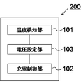
- FIG. 2 the schematic block diagram which shows an example of the charging device which concerns on 2nd Embodiment is shown.
- the charging device 200 includes, in addition to the configuration of the charging device according to the first embodiment, a voltage setting unit 103 that sets a voltage (for example, an upper limit value) related to charging control of the secondary battery at the time of charging.
- the temperature detection unit 101 outputs at least the detected temperature information to the voltage setting unit 103.
- the voltage setting unit 103 sets the upper limit value of the secondary battery voltage based on the temperature information from the temperature detection unit 101.
- the voltage setting unit 103 outputs the set upper limit value information to at least the charge control unit 102.
- the charging control unit 102 controls charging of the secondary battery based on the upper limit value information from the voltage setting unit 103.
- FIG. 3 shows a flowchart for explaining the operation of the charging device according to the first embodiment and the second embodiment, the charging method of the secondary battery, and the program for operating the charging device or controlling the charging method.
- the charging control unit 102 sets the upper limit value of the voltage of the secondary battery at the time of charging to a predetermined first voltage value in order to prevent overcharging. Or the voltage setting part 103 sets the upper limit of the voltage of the secondary battery at the time of charge to a 1st voltage value (S101). The voltage setting unit 103 outputs upper limit value information indicating that the first voltage value has been set to the charging control unit 102.
- the charging control unit 102 starts charging the secondary battery in response to the detection information of the connection between the secondary battery and the charging power source or the upper limit value information from the voltage setting unit 103 (S102).
- the upper limit value of the voltage of the secondary battery may be set after charging is started.
- the charging control unit 102 charges the secondary battery until the voltage of the secondary battery reaches the first voltage value (S103, S104). In S102, in a state where the voltage of the secondary battery is equal to or higher than the first voltage value before the start of charging, the charging control unit 102 does not start charging.
- the temperature detection unit 101 detects the battery-related temperature at least after the charging is stopped (S105). It is preferable that the temperature detection unit 101 performs detection with an interval apart in time. The interval can be appropriately set such as a period of less than 1 second, a period of several seconds, a period of several minutes, etc.
- the temperature detection unit 101 may continue temperature detection from before the start of charging. It is preferable that the temperature detection unit 101 continues temperature detection until at least the battery voltage reaches the second voltage value.
- the temperature detection unit 101 outputs the detected temperature information to at least one of the charge control unit 102 and the voltage setting unit 103.
- the charge control unit 102 or the voltage setting unit 103 responds to the temperature information from the temperature detection unit 101 during charging.
- the upper limit value of the secondary battery voltage is changed to a second voltage value higher than the first voltage value (S106, S107).
- the voltage setting unit 103 sets the upper limit value
- the voltage setting unit 103 outputs upper limit value information indicating that the second voltage value has been set to the charge control unit 102.
- the charging control unit 102 starts charging the secondary battery in response to at least one of the temperature information from the temperature detecting unit 101 and the upper limit value information from the voltage setting unit 103, and the voltage of the secondary battery Until the battery reaches the second voltage value (S108, S109).
- the charging control unit 102 stops charging the secondary battery (S110).
- An appropriate method can be selected as the charging method of the secondary battery. For example, so-called constant current (CC) charging as described later can be selected. Further, constant current charging and so-called constant voltage (CV) charging may be combined. Alternatively, a table indicating the correspondence between the battery voltage and the charging current may be set in advance, and charging may be controlled based on the table.
- CC constant current
- CV constant voltage
- a table indicating the correspondence between the battery voltage and the charging current may be set in advance, and charging may be controlled based on the table.
- the program can be realized by making each step of the above method each processing of the program. The same applies to the following embodiments.
- the battery capacity can be increased.
- the effects of the first embodiment and the second embodiment will be described using a lithium ion secondary battery mounted on an automobile as an example.
- a lithium ion secondary battery mounted on an automobile In an electric vehicle, a high capacity is usually required. For this reason, the charging time must be long. Therefore, it is desired that the secondary battery mounted on the electric vehicle is charged at night when the user does not use the vehicle.
- the nighttime power unit price is usually set lower than the daytime power unit price, so that it is desired that the charging is completed at night in order to reduce the power cost.
- the battery voltage it is necessary to set the battery voltage so that lithium does not precipitate.
- one of the factors affecting the lithium deposition is the temperature of the secondary battery.
- the battery voltage it is necessary to set the battery voltage to be low under low temperature conditions.
- winter nighttime charging particularly in wintertime nighttime charging in cold regions
- the battery voltage lower than the upper limit voltage in daytime charging.
- the first temperature range referred to in the second embodiment is less than 0 ° C. and the second temperature range is set to 0 ° C. or more
- the first voltage value is 4.0V
- the second voltage value is 4.2V.
- the charging is terminated at the first voltage value of 4.0 V, so the capacity of the secondary battery is reduced.
- the battery-related temperature is less than 0 ° C.
- the battery-related temperature may be 0 ° C. or higher during charging or before the user starts using the automobile.
- the secondary battery can be charged to the second voltage value during a time period when the battery is not used, particularly during a time period when the power unit price is low. Accordingly, the secondary battery can be charged to the maximum while the user is not using it, and the power cost can be reduced.
- the upper limit voltage is varied according to the risk of lithium deposition during charging, safety can be ensured.
- FIG. 4 shows a flowchart for explaining the operation of the charging device according to the third embodiment, the charging method of the secondary battery, and the program for operating the charging device or controlling the charging method.
- the configuration of the charging device and the setting of the temperature range in the third embodiment are the same as those in the first embodiment or the second embodiment.
- the upper limit of the voltage of the secondary battery was changed.
- the upper limit voltage is changed when there is a temperature change even during charging to the first voltage value.
- S201 and S202 are the same as S101 and S102 shown in FIG.
- the temperature detection unit 101 detects the battery-related temperature in the same manner as in the first embodiment and the second embodiment (S203).
- the temperature detection unit 101 outputs the detected temperature information to at least one of the charge control unit 102 and the voltage setting unit 103.
- the charge control unit 102 or the voltage setting unit 103 is set to the temperature while the charge control unit 102 continues charging.
- the voltage upper limit value at the time of charging is changed to a second voltage value higher than the first voltage value (S204, S205).
- the subsequent steps are the same as S109 and S110 shown in FIG. 3 (S206, S207).
- the temperature detection unit 101 detects the battery-related temperature again when the battery voltage does not reach the first voltage value. (S208, S203).
- the charging control unit 102 performs charging accordingly. Is stopped (S208, S209).
- the subsequent steps are the same as S105 to S110 shown in FIG. 3 (S210 to S213, S206, S207).
- the same effects as those of the first embodiment and the second embodiment can be obtained. Moreover, since it does not stop charge when it transfers to a 2nd temperature range in the middle of charging in the 1st voltage value, charge can be completed in a shorter time.
- FIG. 5 shows a flowchart for explaining the operation of the charging device according to the fourth embodiment, the charging method of the secondary battery, and the program for operating the charging device or controlling the charging method.
- the configuration of the charging device and the setting of the temperature range in the fourth embodiment are the same as those in the first embodiment and the second embodiment.
- the temperature is detected after starting charging.
- the temperature is detected before starting charging.
- the temperature detection unit 101 detects the battery related temperature in the same manner as in the second embodiment (S301).
- the temperature detection unit 101 outputs the detected temperature information to at least one of the charge control unit 102 and the voltage setting unit 103.
- the charge control unit 102 or the voltage setting unit 103 responds to the temperature information from the temperature detection unit 101 and performs secondary charging at the time of charging.
- the upper limit value of the battery voltage is set to the first voltage value (S303).
- the upper limit value of the voltage of the secondary battery at the time of charging is set to a second voltage value higher than the first voltage value (S310).
- the voltage setting unit 103 sets the upper limit value
- the voltage setting unit 103 outputs information on setting the upper limit value to the charge control unit 102.
- the charging control unit 102 starts charging the secondary battery in response to the temperature information from the temperature detecting unit 101 or the upper limit value information from the voltage setting unit 103 (S304, S311).
- the subsequent flow is the same as S203 to S213 shown in FIG. 4 (S305 to S309, S312 to S317).
- the same effects as those of the first embodiment and the second embodiment can be obtained. Further, a more appropriate voltage upper limit value can be set according to the temperature at the start of charging. Thereby, when the temperature at the start of charging belongs to the second temperature range, charging can be completed in a shorter time.
- the fourth embodiment has been described based on the third embodiment. However, the fourth embodiment can also be applied to the first embodiment and the second embodiment. Other aspects of the fourth embodiment are the same as those of the first and second embodiments.
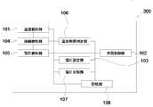
- FIG. 6 the schematic block diagram which shows an example of the charging device which concerns on 5th Embodiment is shown.
- the charging device 300 according to the fifth embodiment is a more preferable form of the charging device according to the first embodiment and the second embodiment.
- the charging device 300 detects a connection between the charging power source and the secondary battery.
- Unit 104 and a voltage detection unit 105 that detects the voltage of the secondary battery.
- the charging device 300 includes a storage unit 108 that stores various data, a temperature range determination unit 106 that determines a temperature range to which the temperature detected by the temperature detection unit 101 belongs, a set upper limit value, and a voltage of the secondary battery And a voltage comparison unit 107 that compares the magnitudes of the two with respect to each other.
- the storage unit 108 includes, for example, an upper limit voltage value corresponding to a temperature range, a temperature range during charging, a current value during constant current charging, a charging voltage value during constant voltage charging, a charging end current value during constant voltage charging, and a charging start voltage value. Necessary information is stored appropriately. Note that the charging device 300 may not include all the above-described units.
- the connection detection unit 104 can be configured to output the detected connection information to at least the temperature detection unit 101 and the voltage detection unit 105.
- the temperature detection unit 101 can be configured to detect a battery-related temperature based on connection information from the connection detection unit 104.
- the temperature detection unit 101 can be configured to output the detected temperature information to at least one of the temperature range determination unit 106, the voltage setting unit 103, and the charge control unit 102.
- the voltage detection unit 105 can be configured to detect the voltage of the secondary battery based on the connection information from the connection detection unit 104.
- the voltage detection unit 105 can be configured to output the detected voltage information to at least the voltage comparison unit 107 and the charge control unit 102.
- the temperature range determination unit 106 can be configured to determine the temperature range to which the battery-related temperature belongs based on the temperature information from the temperature detection unit 101.
- the temperature range determination unit 106 can be configured to output the determined temperature range information to at least one of the voltage setting unit 103 and the charge control unit 102.
- the charging control unit 102 or the voltage setting unit 103 can be configured to set the upper limit value based on the temperature range information from the temperature range determination unit 106.
- the voltage setting unit 103 sets the upper limit value
- the voltage setting unit 103 can be configured to output the set upper limit value information to at least one of the charge control unit 102 and the voltage comparison unit 107.
- the voltage comparison unit 107 can be configured to compare the set upper limit value with the voltage value of the secondary battery.
- the voltage comparison unit 107 can be configured to output at least the comparison result information to the charge control unit 102.
- the charging control unit 102 can be configured to control charging of the secondary battery based on at least one of information from each unit.
- FIG. 7 shows a flowchart for explaining the operation of the charging apparatus according to the fifth embodiment, the charging method of the secondary battery, and the program for operating the charging apparatus or controlling the charging method.
- the operation and the charging method of the charging device according to the fifth embodiment based on the fourth embodiment will be described, but the fifth embodiment can also be applied to the first to third embodiments.
- connection detection unit 104 detects whether the secondary battery and the charging power source are electrically connected (S401). For example, in the case of a secondary battery mounted on an electric vehicle, the connection detection unit 104 detects whether the in-vehicle charger and the charging power source are connected. In the case of a secondary battery mounted on a portable device, the connection detection unit 104 detects whether the charger connected to the power source and the portable device are connected. The connection detection unit 104 outputs connection information with the charging power source to at least the temperature detection unit 101 and the voltage detection unit 105. The connection detection unit 104 may output the connection information to another unit.
- the temperature detection unit 101 detects at least the battery-related temperature after the connection is confirmed (S402).
- the temperature detection unit 101 may detect the temperature before connecting the secondary battery and the charging power source. Thereafter, the temperature detection unit 101 continues to detect the battery-related temperature at intervals until at least the secondary battery reaches the second voltage value regardless of whether charging is being performed or charging is being stopped. In FIG. 7, temperature detection after S402 is not shown.
- the temperature range determination unit 106 refers to the storage unit 108 and determines to which temperature range the temperature detected by the temperature detection unit 101 belongs ( S403).
- the temperature range determination unit 106 may determine the temperature range based on the instantaneous temperature, or may determine the temperature range based on the temperature for a certain period or the average temperature. For example, the temperature range determination unit 106 may determine the temperature range based on one piece of temperature information, or may determine the temperature range based on a plurality of temperature information for a predetermined period.
- the storage unit 108 preferably stores the correspondence relationship between the temperature and the temperature range in advance.
- the temperature range determination unit 106 outputs the determined temperature range information to at least one of the voltage setting unit 103 and the charge control unit 102.
- the charging control unit 102 or the voltage setting unit 103 refers to the storage unit 108 and corresponds the upper limit value of the secondary battery voltage to the temperature range.
- Set to voltage value The storage unit 108 preferably stores the correspondence relationship between the temperature range and the upper limit voltage in advance.
- the charge control unit 102 or the voltage setting unit 103 sets the upper limit voltage to the first voltage value (S404).
- the charge control unit 102 or the voltage setting unit 103 sets the upper limit voltage to the second voltage value (S412).
- the storage unit 108 stores the set upper limit voltage value.
- the voltage setting unit 103 sets the upper limit value
- the voltage setting unit 103 outputs the set upper limit value information to the voltage comparison unit 107 and the charge control unit 102.
- the voltage detection unit 105 detects the voltage of the secondary battery in response to the connection information from the connection detection unit 104. It is preferable that the voltage detector 105 continuously detects the battery voltage after connection with the charging power source with a time interval. The voltage detection unit 105 outputs voltage value information of the detected secondary voltage to the voltage comparison unit 107.
- the voltage comparison unit 107 compares the voltage value of the secondary battery with the set upper limit value (S405, S413).
- the voltage comparison unit 107 outputs the comparison result information to the charge control unit 102.
- the charging control unit 102 starts charging the secondary battery in response to the comparison result information from the voltage comparison unit 107 (S406, S414). If the battery voltage is greater than or equal to the upper limit voltage value, the temperature detection step (S402) and subsequent steps are repeated.
- the charging control unit 102 receives a predetermined first voltage value or The secondary battery may be charged by setting the two voltage value to the upper limit value of the battery voltage.
- the charging start voltage value can be set to a voltage value different from the upper limit value.
- the charging start voltage value is set to a voltage value lower than the first voltage value, and the storage unit 108 stores the charging start voltage value.
- the voltage comparison unit 107 compares the battery voltage value with the charge start voltage value. Then, the charging control unit 102 starts charging when the battery voltage value is less than the charging start voltage value. Even if the battery voltage value is less than the first voltage value, the charging control unit 102 does not start charging if the battery voltage value is equal to or higher than the charging start voltage value.
- the voltage detection step and the voltage comparison step may be performed before the temperature detection step.
- the voltage comparison unit 107 determines whether the battery voltage has reached the second voltage value.
- the charging control unit 102 stops charging in response to the comparison result information from the voltage comparing unit 107 (S410, S411). In this case, since the voltage upper limit at the time of charging is set to the maximum value in the allowable range, the secondary battery can be charged to the maximum capacity.
- the charging control unit 102 Charging is stopped in response to the comparison result information from the comparison unit 107 (S407, S415). In this case, even after charging is stopped, the temperature detection unit 101 continues to detect the battery-related temperature.
- the voltage setting unit 103 sets the upper limit value of the voltage of the secondary battery to the second value. The voltage value is changed (S416, S417).
- the charging control unit 102 starts charging in response to the temperature range information from the temperature range determining unit 106 or the upper limit value information from the voltage setting unit 103, and the voltage of the secondary battery is set in the same manner as described above.
- the secondary battery is charged until the second voltage value is reached (S418, S410, S411).
- the temperature range determination unit 106 In response to the temperature range information from, the charging control unit 102 or the voltage setting unit 103 changes the upper limit value of the voltage of the secondary battery to the second voltage value during charging (S407 to S409). Next, the charging control unit 102 continues charging and charges the secondary battery until the voltage of the secondary battery reaches the second voltage value in the same manner as described above (S410, S411).
- the same effects as those of the first embodiment and the second embodiment can be obtained.
- a more appropriate upper limit value can be set according to the temperature state regardless of whether charging is being performed or not being stopped.
- the time during which charging is stopped can be reduced. Thereby, charging can be completed safely and in a short time.
- the charging device 300 according to the fifth embodiment can also be applied to the first to fourth embodiments.
- Other aspects of the fifth embodiment are the same as those of the first to fourth embodiments.
- FIG. 8 shows a flowchart for explaining the operation of the charging apparatus according to the sixth embodiment, the charging method of the secondary battery, and the program for operating the charging apparatus or controlling the charging method.
- the configuration of the charging device and the setting of the temperature range in the sixth embodiment are the same as in the fifth embodiment.
- the sixth embodiment is a preferred charging mode of the fifth embodiment.
- the operation and the charging method of the charging device according to the sixth embodiment based on the fifth embodiment will be described, but the sixth embodiment can also be applied to the first to fourth embodiments.
- connection detection unit 104 detects whether the secondary battery and the charging power source are electrically connected (S501).
- the connection detection unit 104 outputs connection information with the charging power source to the temperature detection unit 101 and the voltage detection unit 105.
- the connection detection unit 104 may output the connection information to another unit.
- the voltage detection unit 105 detects the voltage of the secondary battery. Thereafter, it is preferable that the voltage detection unit 105 continuously detects the battery voltage at intervals separated in time. The voltage detection unit 105 outputs the detected information to the voltage comparison unit 107. Next, in response to the voltage information from the voltage detection unit 105, the voltage comparison unit 107 compares the detected voltage value with a preset charging start voltage value. As described above, the charging start voltage value may be the same value as the upper limit value during charging or may be a different value. In response to the connection information from the connection detection unit 104, the temperature detection unit 101 detects the battery-related temperature after the connection detection unit 104 detects the connection (S502, S503).
- the temperature detection is performed after the voltage comparison, but the voltage comparison and the temperature detection before and after are not limited. Further, the temperature detection unit 101 may detect the temperature before connecting the secondary battery and the charging power source. The temperature detection unit 101 outputs the detected temperature information to the temperature range determination unit 106.
- the temperature range determination unit 106 based on the temperature information from the temperature detection unit 101, the temperature range determination unit 106 refers to the storage unit 108, and to which temperature range the temperature detected by the temperature detection unit 101 is. It is determined whether it belongs (S504).
- the temperature range determination unit 106 outputs temperature range information to at least one of the voltage setting unit 103 and the charge control unit 102.
- the charge control unit 102 or the voltage setting unit 103 refers to the storage unit 108 in response to the temperature range information of the temperature range determination unit 106, and the secondary battery Is set to the first voltage value (S505).
- the voltage setting unit 103 sets the upper limit value
- the voltage setting unit 103 outputs the upper limit value information to the charge control unit 102.
- the voltage comparison unit 107 compares the battery voltage with a predetermined third voltage value based on the voltage information from the voltage detection unit 105 (S506).
- the voltage comparison unit 107 outputs the comparison result information to the charge control unit 102.
- the third voltage value is a voltage value for completing charging in a shorter time without depositing a hazardous substance such as lithium when charging in the first temperature range. That is, when the battery voltage reaches the third voltage value, the charging control unit 102 switches the charging format. In order to shorten the charging time, it is preferable to charge at a higher current. However, when the battery-related temperature is low and the battery voltage is high, charging with a high current may generate lithium or lithium compounds with high risk. For example, when charging to a first voltage value (for example, 4.1 V or more) with a high current in a first temperature range (for example, less than 0 ° C.), there is a high risk that dangerous substances are deposited in the vicinity of the first voltage value.
- a first voltage value for example, 4.1 V or more
- a high current in a first temperature range for example, less than 0 ° C.
- the third voltage value is a voltage value set so that lithium or the like is not generated even when charged with a high current (first current value in the following form). Therefore, the third voltage value is set lower than the first voltage value.
- the voltage setting unit 103 refers to the storage unit 108 in response to the comparison result information from the voltage comparison unit 107, and switches the charging format.
- the voltage value may be set to the third voltage value (S507).
- the voltage setting unit 103 outputs information on setting the switching voltage value to the charge control unit.
- the charge control unit 102 starts charging at the first current value until the third voltage value is reached (S508; first constant) Current charging step).
- the first current value can be changed according to the temperature.
- the first current value is preferably determined in advance.
- the voltage setting unit 103 sets the upper limit value of the battery voltage during charging to the second voltage value in the same manner as in the above embodiment. Change (S509 to S511).
- the charging control unit 102 continues the constant current charging until the second voltage value is reached. At this time, the charging control unit 102 may change the charging current value. For example, since the risk of deposition of hazardous substances has decreased due to the increase in temperature, the charging control unit 102 may charge with a second current value higher than the first current value (S512). Thereby, charging can be completed in a shorter time.
- the second current value is preferably determined in advance.
- the charge control unit 102 switches to charge at the second voltage value (S513, S514). Constant voltage charging step). Thereby, battery capacity can be raised more.
- the charging control unit 102 stops charging (S515, S516).
- the charging control unit 102 or the voltage setting unit 103 responds to the temperature range information from the temperature range determination unit 106 and the upper limit value of the voltage of the secondary battery Is set to the second voltage value (S504, S517). Then, the charging control unit 102 starts charging at the second current value until the second voltage value is reached (S518). The subsequent flow is the same as S513 to S516.
- the charging control unit 102 Based on the result from the comparison unit 107, charging is started at the third current value until the first set value is reached (S519).
- the third current value is set to a current that does not generate a dangerous substance such as lithium even when charged when the temperature is low and the battery voltage is high.
- the third current value is preferably lower than the first current value.
- the third current value is preferably determined in advance.
- the charging control unit 102 displays the voltage comparing unit 107. In response to the comparison result information from, charging is continued by switching the charging current from the first current value to the third current value (S520; second constant current charging step).
- the charging control unit 102 may switch the charging format in response to information from the voltage setting unit 103.
- the charging control unit 102 or the voltage setting unit 103 In response to the temperature range information from temperature range determination unit 106, the upper limit value of the voltage of the secondary battery is changed to the second voltage value (S521, S511). The subsequent flow is the same as S512 to S516.
- the charge control unit 102 compares the voltage from the voltage comparison unit 107. In response to the result information, switching to charging at the first voltage value is performed (S522, S523; constant voltage charging step). When the charging current becomes equal to or less than a predetermined current value (charging end current value), the charging control unit 102 stops charging (S524, S525).
- the charging control unit 102 or the voltage setting unit 103 determines whether the temperature range determination unit 106 In response to the temperature range information, the upper limit value of the voltage of the secondary battery is changed from the first voltage value to the second voltage value (S526, S527). Then, in response to the temperature range information from the temperature range determination unit 106 or the upper limit value information from the voltage setting unit 103, the charging control unit 102 starts charging at the second current value until the second voltage value is reached ( S528). The subsequent flow is the same as S513 to S516.
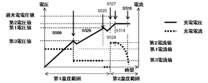
- 9 to 12 are schematic views showing transitions of the charging voltage and charging current in the sixth embodiment. 9 to 12, the solid line indicates the charging voltage, and the broken line indicates the charging current. 9 to 12, the step number (S) shown in FIG. 8 is added to indicate the correspondence.
- the charging current is controlled to be constant, and the battery voltage rises.
- the constant voltage charging section the battery voltage is controlled to be constant, and the charging current is attenuated. When the charging current is lowered in constant current charging, a voltage drop due to internal resistance occurs.
- FIG. 9 shows an example in which charging is started in the first temperature range, and charging is stopped without changing the temperature range.
- the upper limit voltage is switched to the first voltage value, and the charging current is switched from the first current value to the third current value.
- FIG. 10 shows an example in which charging is started in the first temperature range and the second temperature range is reached before reaching the third voltage value.
- the upper limit voltage is switched to the second voltage value by changing the temperature range, and the charging current is switched from the first current value to the second current value.
- FIG. 11 shows an example in which charging is started in the first temperature range, the third voltage value is reached, and then the second temperature range is reached before the first voltage value is reached.
- the upper limit voltage is switched to the first voltage value, and the charging current is switched from the first current value to the third current value.
- the upper limit voltage is switched to the second voltage value, and the charging current is switched from the third current value to the second current value.
- FIG. 12 shows an example in which charging is started in the first temperature range, charging is performed up to the first voltage value, charging is stopped, and then the second temperature range is entered.
- the upper limit voltage is switched to the first voltage value, and the charging current is switched from the first current value to the third current value. Thereafter, the battery is charged to the first voltage value, and charging is stopped.
- the upper limit voltage is switched to the second voltage value, the charging current is switched from the third current value to the second current value, and charging is resumed.
- the form in which the temperature range changes during constant voltage charging was not shown.
- the present invention can be applied in the same manner as the case where the temperature changes during constant current charging.
- constant current charging is divided into two stages in the first temperature range, it can be divided into three or more stages. In this case, the switching voltage value is set for each stage.
- constant current charging was not divided in stages in the second temperature range, but constant current charging can also be divided into two or more stages in the second temperature range.
- the same effects as those of the first embodiment and the second embodiment can be obtained.
- charging is performed at a high current at the first stage where the battery voltage is low, so that the charging time can be shortened.
- the second stage where the battery voltage is high charging is performed with a low current, so that precipitation of lithium or the like can be prevented.
- the upper limit voltage and the charging current are selected according to the temperature range, the charging efficiency can be increased. Therefore, safe and high-speed charging can be performed as a whole.
- constant voltage charging was performed at the first voltage value in the first temperature range.
- constant voltage charging at the first voltage value is not performed, and the battery voltage reaches the first voltage value by constant current charging at the third current value.
- the flowchart of the seventh embodiment is the same as the flowchart of FIG. 8 in the sixth embodiment, except that the step of S523 shown in FIG. 8 does not exist.
- FIG. 13 and FIG. 14 are schematic views showing transitions of the charging voltage and charging current in the seventh embodiment.
- FIG. 13 shows an example in which charging is started in the first temperature range, and charging is stopped without changing the temperature range.
- the upper limit voltage is switched to the first voltage value, and the charging current is switched from the first current value to the third current value.
- constant voltage charging at the first voltage value is not performed.
- FIG. 14 shows an example in which charging is started in the first temperature range, charging is performed up to the first voltage value, charging is stopped, and then the second temperature range is entered.
- the upper limit voltage is switched to the first voltage value, and the charging current is switched from the first current value to the third current value. Thereafter, the battery is charged to the first voltage value, and charging is stopped.
- the upper limit voltage is switched to the second voltage value, the charging current is switched from the third current value to the second current value, and charging is resumed.
- constant voltage charging at the first voltage value is not performed in the first temperature range.
- the operation of the charging device according to the eighth embodiment, the charging method of the secondary battery, and the program for operating the charging device or controlling the charging method will be described.
- the configuration of the charging device and the setting of the temperature range in the eighth embodiment are the same as those in the fifth embodiment.
- the temperature range is divided into two, but the temperature range may be divided into three or more. Since it is the same as that of the said embodiment except that the temperature range increased, illustration of a flowchart is abbreviate
- FIG. 15 is a schematic diagram showing the transition of the charging voltage and charging current in the eighth embodiment.
- the third temperature range is set on the lower temperature side than the first temperature range.
- the first temperature range and the third temperature range are adjacent to each other.
- the boundary temperature between the first temperature range and the third temperature range can be arbitrarily set.
- the third temperature range can be a region below ⁇ 10 ° C.
- the first temperature range can be a region from ⁇ 10 ° C. to less than 0 ° C.
- the second temperature range can be a region above 0 ° C.
- the charging current for constant current charging in the third temperature range is preferably set to a fourth charging current lower than the first charging current for constant current charging in the first temperature range. This is because in the case of a lithium ion battery, the lower the temperature, the more likely the dangerous substances are deposited.
- FIG. 15 shows an example in which charging is started in the third temperature range and the first temperature range is reached before the fourth voltage value is reached. After shifting to the first temperature range, the configuration is the same as that shown in FIG.
- charging can be performed safely and quickly even in extreme cold conditions such as winter nights in cold regions.
- the eighth embodiment can be applied to the first to seventh embodiments. Other aspects of the eighth embodiment are the same as those of the first to seventh embodiments.
- FIG. 16 shows a flowchart for explaining the operation of the charging apparatus according to the ninth embodiment, the charging method of the secondary battery, and the program for operating the charging apparatus or controlling the charging method.
- the configuration of the charging device and the setting of the temperature range in the ninth embodiment are the same as those in the fifth embodiment.
- the battery-related temperature is in the second temperature range, and after the upper limit value of the voltage of the secondary battery is set or changed to the second voltage value, the battery-related temperature is the first temperature. The form when it comes to belong to the range is shown.
- FIG. 16 shows a partial flow when shifting from the second temperature range to the first temperature range.
- the charging control unit 102 or the voltage setting unit 103 sets the upper limit value of the battery voltage during charging to the second voltage value (S601). Then, the charging control unit 102 starts charging at the second current value until the second voltage value is reached (S602). Subsequent S603 to S608 are the same as those in the above embodiments.
- the charge control unit 102 or the voltage setting unit 103 responds to the temperature range information from the temperature range determination unit 106, and the voltage upper limit at the time of charging The value is changed to the first voltage value (S609).
- the voltage comparison unit 107 confirms whether the battery voltage is less than the first voltage value in response to the voltage information from the voltage detection unit 105 (S610).
- the charging control unit 102 charges to the first voltage value and stops the charging (S611 to S613, S607, S608) in the same manner as each of the above embodiments. .
- the charging control unit 102 stops charging without performing charging (S608).
- the voltage comparison unit 107 determines that the battery voltage is less than the third voltage value before S610. Separately perform the step of confirming.
- the charging control unit 102 performs the first constant current charging step, the second constant current charging step, and the constant voltage charging step in the same manner as in the above embodiments. Charge to the first voltage value and stop charging.
- the charging control unit 102 performs the second constant current charging step and the constant voltage charging step to charge to the first voltage value and stops charging.
- the ninth embodiment can be applied to the first to eighth embodiments. Other aspects of the ninth embodiment are the same as those of the first to eighth embodiments.
- the ninth embodiment during charging, when a battery-related temperature shifts from the second temperature range to the first temperature range due to factors such as a decrease in air temperature, a stop of a heating appliance or a heating device, a dangerous substance is deposited. Risk can be reduced.
- FIG. 17 is a schematic diagram illustrating an example of a power storage system according to the tenth embodiment.
- the power storage system 400 includes a secondary battery 402 having at least one cell, at least one of the charging devices 100, 200, 300 according to the embodiment connected to the secondary battery 402, and the charging devices 100, 200, And a temperature sensor 401 connected to 300.
- a charging power source is detachably connected to charging devices 100, 200, and 300.
- Charging devices 100, 200, and 300 charge secondary battery 402.
- the temperature sensor 401 is a sensor that detects the battery-related temperature described above.
- the temperature sensor 401 can be installed, for example, so as to detect the temperature of at least one of cell conductors, between cells, and a conductor connected to the cells.
- the temperature sensor 401 may be installed so as to detect the temperature of the environment where the secondary battery 402, the charging devices 100, 200, 300, or the power storage system 400 is placed, for example.
- a plurality of temperature sensors 401 may be installed so as to detect temperatures at a plurality of locations.
- the charging method by the power storage system 400 is the same as the charging method described above.
- the same effect as that of the charging device according to the above embodiment can be obtained.
- the battery capacity of the secondary battery can be further increased when the battery-related temperature increases after the start of charging. Moreover, it can charge in a shorter time. Furthermore, charging can be performed safely.
- FIG. 18 is a schematic diagram illustrating an example of a power storage system according to the eleventh embodiment.
- the power storage system according to the eleventh embodiment is a preferred form of the power storage system according to the tenth embodiment.
- the power storage system 500 includes a secondary battery 402 having at least one cell, a battery management unit (BMU) 403 for performing charge control and discharge control of the secondary battery 402 and protection management of the secondary battery 402, Power conditioner (PCS) 404 that performs conversion of DC power and AC power between the secondary battery 402 and the power source and load, voltage and frequency adjustment, and control and monitoring of the BMU 403 and PCS A system controller (SC) 405 to be executed.
- the BMU 403, the PCS 404, and the SC 405 are connected so that they can communicate with each other.
- a charging power source is connected to the PCS 404.
- PCS and SC are illustrated as separate elements, but the illustrated form includes a form in which PCS and CS are incorporated into one element.
- the charging devices 100, 200, and 300 according to the above embodiment are incorporated in the BMU 403.
- the temperature sensor 401 and the secondary battery 402 are connected to the charging devices 100, 200, and 300.
- the program can be incorporated into SC405, for example.
- the program causes the charging device to execute the operation of each unit and each step of the charging method.
- the same effect as in the tenth embodiment can be obtained.
- the charging device, the power storage system, the charging method, and the program of the present invention have been described based on the above embodiment, but are not limited to the above embodiment, and are within the scope of the present invention and the basic of the present invention.
- Various modifications, changes, and improvements may be included in various disclosed elements (including each element of each claim, each element of each embodiment or example, each element of each drawing, etc.) based on the technical idea. Needless to say, it can be done.
- Various combinations and replacements of various disclosed elements including each element of each claim, each element of each embodiment or example, each element of each drawing, etc. within the scope of the entire disclosure of the present invention. Selection is possible.
- Each step of the method can be a program processing step.
- a temperature detector In response to the detection result of the first temperature within the first temperature range determined in advance by the temperature detection unit, the upper limit value of the voltage of the secondary battery corresponds to the first temperature range.
- a charge control unit that performs control to vary the voltage value and charge the secondary battery until the upper limit value is reached;
- a charging device comprising:
- [Appendix 3] Responding to the detection result of the temperature within the first temperature range from the temperature within the second temperature range at the temperature detection unit that has detected the second temperature within the predetermined second temperature range.
- the charge control unit varies the upper limit value from the second voltage value corresponding to the second temperature range to the first voltage value, and charging is performed when the upper limit value is the second voltage value.
- a charging device that performs control to continue the charging of the secondary battery in the battery and charge the secondary battery to the first voltage value that is the new upper limit value.
- the charge control unit sets the upper limit value to the second voltage value based on the detected temperature belonging to the second temperature range, and the detected temperature is higher than the second temperature range.
- a charging device that sets the upper limit value to the first voltage value based on belonging to the first temperature range within the range.
- the charging device including the first temperature range including a range of 0 ° C or more.
- the charging control unit is a charging device that varies the upper limit value from the first voltage value to the second voltage value.
- the charge control unit In response to detecting that the voltage has reached the second voltage value, the charge control unit is configured to control the secondary battery at the second voltage value until a predetermined third current value is reached.
- a charging device that performs charging.
- the charge control unit In response to the temperature information from the temperature detection unit that has detected a temperature belonging to the first temperature range, the charge control unit is configured to output the secondary battery until the voltage of the secondary battery reaches the first voltage value. The battery is charged with a fourth current value, and in response to detecting that the voltage has reached the first voltage value, the charge control unit is configured to change a charging current to a fifth current value that is set in advance. A charging device that charges the secondary battery at the first voltage value until it becomes.
- a temperature detector Based on the temperature detected by the temperature detector, a voltage setting unit that variably sets the upper limit of the voltage of the secondary battery, In response to the upper limit value information from the voltage setting unit that has varied the upper limit value based on a detection result of a first temperature within a predetermined first temperature range in the temperature detection unit, A charge control unit that performs control to charge the secondary battery until the upper limit is reached;
- a charging device comprising:
- the charge control unit determines that the upper limit value is the second voltage value. Then, the charging device that performs the control to start charging the secondary battery that has been stopped and charge the secondary battery to the second voltage value that is the new upper limit value.
- the voltage setting unit sets the upper limit value to the second voltage value based on the detected temperature belonging to the second temperature range, and the detected temperature is higher than the second temperature range.
- a charging device that sets the upper limit value to the first voltage value based on belonging to the first temperature range.
- the charging device including the first temperature range including a range of 0 ° C or more.
- the voltage setting unit is a charging device that varies the upper limit value from the first voltage value to the second voltage value.
- the charge control unit In response to the upper limit value information from the voltage setting unit that sets the upper limit value to the second voltage value, the charge control unit is configured to set a voltage of the secondary battery to a predetermined third voltage value. A second current lower than the first current value in response to detecting that the voltage has reached the third voltage value. A charging device that charges the secondary battery until the second voltage value is reached.
- the charge control unit In response to detecting that the voltage has reached the second voltage value, the charge control unit is configured to control the secondary battery at the second voltage value until a predetermined third current value is reached.
- a charging device that performs charging.
- the charging control unit In response to the upper limit value information from the voltage setting unit that sets the upper limit value to the first voltage value, the charging control unit is configured to increase the voltage of the secondary battery to the first voltage value. In response to detecting that the secondary battery is charged with a fourth current value and the voltage has reached the first voltage value, the charge control unit is configured to output a third charge current. A charging device that charges the secondary battery at the first voltage value until a current value is reached.
- the temperature detected by the temperature detector is at least one of the temperature of any part of the secondary battery, the temperature of the environment where the secondary battery is placed, and the temperature of the environment where the charging device is placed. Is a charging device.
- the said temperature detection part is a charging device which performs the detection which left
- Appendix 28 A charging device according to the appendix, The secondary battery connected to the charging device; And a temperature sensor connected to the temperature detection unit.
- a battery management unit for managing charge and discharge of the secondary battery is a power storage system including the charging device.
- a power conditioner for connecting the secondary battery and a charging power source;
- a system controller for controlling the battery management unit and the power conditioner;
- the battery management unit, the power conditioner, and the system controller are connected to each other.
- the charging method further comprising the step of charging the secondary battery until the voltage of the secondary battery reaches the first voltage value and stopping the charging.
- the charging method further comprising the step of charging the secondary battery until the voltage of the secondary battery reaches the first voltage value and stopping the charging.
- [Appendix 42] Charging the secondary battery with the first voltage value as the upper limit value; The process is Charging the secondary battery with a first current value until a predetermined third voltage value is reached; In response to the voltage of the secondary battery reaching the third voltage value, the secondary battery has a second current value lower than the first current value until the first voltage value is reached. And a step of charging the battery.
- a charging current is predetermined in response to the voltage of the secondary battery reaching the first voltage value.
- a method for charging a secondary battery further comprising a step of charging the secondary battery at the first voltage value until reaching a third current value.
- [Appendix 44] Charging the secondary battery to the second voltage value, Charging the secondary battery with a fourth current value until the voltage of the secondary battery reaches the second voltage value; In response to the voltage of the secondary battery reaching the second voltage value, the secondary battery is charged with the second voltage value until a charging current reaches a predetermined fifth current value. And charging the secondary battery.
- the temperature is at least one of a temperature of any part of the secondary battery, a temperature of an environment where the secondary battery is placed, and a temperature of an environment where a power storage system for charging the secondary battery is placed. Charging method which is one temperature.
- Appendix 50 At least a secondary in which the temperature is detected at a time interval from when the secondary battery and the charging power source are connected until the voltage of the secondary battery reaches the second voltage value. How to charge the battery.
- the charging device, power storage system, charging method, and program of the present invention can be suitably applied to charging a secondary battery, particularly a lithium ion battery.
- a secondary battery particularly a lithium ion battery.
- the present invention can be suitably applied to automobiles, portable devices, electric motors, portable power sources, and the like equipped with secondary batteries.
Landscapes
- Engineering & Computer Science (AREA)
- Chemical & Material Sciences (AREA)
- Manufacturing & Machinery (AREA)
- Chemical Kinetics & Catalysis (AREA)
- Electrochemistry (AREA)
- General Chemical & Material Sciences (AREA)
- Power Engineering (AREA)
- Materials Engineering (AREA)
- Charge And Discharge Circuits For Batteries Or The Like (AREA)
- Secondary Cells (AREA)
Abstract
Description
本発明は、日本国特許出願:特願2013-228668号(2013年11月1日出願)に基づくものであり、同出願の全記載内容は引用をもって本書に組み込み記載されているものとする。
本発明は、二次電池を充電するための充電装置に関する。本発明は、当該充電装置を備える蓄電システムに関する。本発明は、二次電池を充電する充電方法に関する。また、本発明は、当該充電装置を動作させるプログラムないし当該充電方法を制御するプログラムに関する。
温度検知部と、
前記温度検知部での予め定められた第1の温度範囲内の第1の温度の検知結果に応答して、二次電池の電圧の上限値を前記第1の温度範囲に対応する第1の電圧値に可変させ、前記二次電池の充電を前記上限値に達するまでとする制御を行う充電制御部と、
を備える充電装置。
予め定められた第2の温度範囲内の第2の温度を検知していた前記温度検知部での前記第2の温度範囲内の温度から前記第1の温度範囲内の温度の検知結果に応答して、前記充電制御部は、前記第2の温度範囲に対応する第2の電圧値から前記第1の電圧値に前記上限値を可変させ、前記上限値が前記第2の電圧値では停止していた前記二次電池の充電を開始し、前記二次電池をあらたな前記上限値である前記第1の電圧値まで充電する制御を行う充電装置。
予め定められた第2の温度範囲内の第2の温度を検知していた前記温度検知部での前記第2の温度範囲内の温度から前記第1の温度範囲内の温度の検知結果に応答して、前記充電制御部は、前記第2の温度範囲に対応する第2の電圧値から前記第1の電圧値に前記上限値を可変させ、前記上限値が前記第2の電圧値では充電中の前記二次電池に対して前記充電を継続し、前記二次電池をあらたな前記上限値である前記第1の電圧値まで充電する制御を行う充電装置。
前記第1の電圧値は前記第2の電圧値よりも高い充電装置。
前記充電制御部は、前記検知温度が前記第2の温度範囲に属することに基づいて前記上限値を前記第2の電圧値に設定し、前記検知温度が、前記第2の温度範囲よりも高い範囲にある前記第1の温度範囲に属することに基づいて前記上限値を前記第1の電圧値に設定する充電装置。
前記第2の温度範囲は0℃未満の範囲を含む充電装置。
前記第1の温度範囲は0℃以上の範囲を含む充電装置。
前記第1の温度範囲内の温度を検知していた前記温度検知部での前記第1の温度範囲から前記第2の温度範囲内の温度の検知結果に基づき、
前記充電制御部は、前記上限値を前記第1の電圧値から前記第2の電圧値に可変させる充電装置。
前記第2の温度範囲に属する温度を検知した前記温度検知部からの温度情報に応答して、前記充電制御部は、前記二次電池の電圧が予め定められた第3の電圧値に達するまで前記二次電池を第1の電流値で充電し、前記電圧が前記第3の電圧値に達したことの検出に応答して、前記第1の電流値よりも低い第2の電流値で前記第2の電圧値に達するまで前記二次電池の充電を行う充電装置。
前記電圧が前記第2の電圧値に達したことの検出に応答して、前記充電制御部は、予め定められた第3の電流値となるまで前記第2の電圧値で前記二次電池の充電を行う充電装置。
前記第1の温度範囲に属する温度を検知した前記温度検知部からの温度情報に応答して、前記充電制御部は、前記二次電池の電圧が前記第1の電圧値に達するまで前記二次電池を第4の電流値で充電し、前記電圧が前記第1の電圧値に達したことの検出に応答して、前記充電制御部は、充電電流が予め定められた第5の電流値となるまで前記第1の電圧値で前記二次電池の充電を行う充電装置。
前記第4の電流値は、前記第1の電流値よりも高い充電装置。
温度検知部と、
前記温度検知部での検知温度に基づき、二次電池の電圧の上限値を可変に設定する電圧設定部と、
前記温度検知部での予め定められた第1の温度範囲内の第1の温度の検知結果に基づき、前記上限値を可変させた前記電圧設定部からの前記上限値情報に応答して、前記二次電池の充電を前記上限値に達するまでとする制御を行う充電制御部と、
を備える充電装置。
前記上限値を第2の電圧値から前記第1の電圧値に変更した前記電圧設定部からの前記上限値情報に応答して、前記充電制御部は、前記上限値が前記第2の電圧値では停止していた前記二次電池の充電を開始し、前記二次電池をあらたな前記上限値である前記第2の電圧値まで充電する制御を行う充電装置。
前記上限値を第2の電圧値から前記第1の電圧値に変更した前記電圧設定部からの前記上限値情報に応答して、前記充電制御部は、前記上限値が前記第2の電圧値では充電中の前記二次電池に対して前記充電を継続し、前記二次電池をあらたな前記上限値である前記第2の電圧値まで充電する制御を行う充電装置。
前記第2の電圧値は前記第1の電圧値よりも高い充電装置。
前記電圧設定部は、前記検知温度が第2の温度範囲に属することに基づいて前記上限値を前記第2の電圧値に設定し、前記検知温度が、前記第2の温度範囲よりも高い範囲にある前記第1の温度範囲に属することに基づいて前記上限値を前記第1の電圧値に設定する充電装置。
前記第2の温度範囲は0℃未満の範囲を含む充電装置。
前記第1の温度範囲は0℃以上の範囲を含む充電装置。
前記第1の温度範囲内の温度を検知していた前記温度検知部での前記第1の温度範囲から前記第2の温度範囲内の温度の検知結果に基づき、
前記電圧設定部は、前記上限値を前記第1の電圧値から前記第2の電圧値に可変させる充電装置。
前記上限値を前記第2の電圧値に設定した前記電圧設定部からの前記上限値情報に応答して、前記充電制御部は、前記二次電池の電圧が予め定められた第3の電圧値に達するまで前記二次電池を第1の電流値で充電し、前記電圧が前記第3の電圧値に達したことの検出に応答して、前記第1の電流値よりも低い第2の電流値で前記第2の電圧値に達するまで前記二次電池の充電を行う充電装置。
前記電圧が前記第2の電圧値に達したことの検出に応答して、前記充電制御部は、予め定められた第3の電流値となるまで前記第2の電圧値で前記二次電池の充電を行う充電装置。
前記上限値を前記第1の電圧値に設定した前記電圧設定部からの前記上限値情報に応答して、前記充電制御部は、前記二次電池の電圧が前記第1の電圧値に達するまで前記二次電池を第4の電流値で充電し、前記電圧が前記第1の電圧値に達したことの検出に応答して、前記充電制御部は、充電電流が予め定められた第3の電流値となるまで前記第1の電圧値で前記二次電池の充電を行う充電装置。
前記第5の電流値は、前記第1の電流値よりも高い充電装置。
前記温度検知部が検知する温度は、前記二次電池のいずれかの部分の温度、前記二次電池が置かれた環境の温度及び前記充電装置が置かれた環境の温度のうちの少なくとも1つである充電装置。
前記二次電池はリチウムイオン電池である充電装置。
前記温度検知部は、前記充電制御部が充電を停止している状態及び充電を行っている状態において時間的に離間して間隔をもった検知を行う充電装置。
付記に係る充電装置と、
前記充電装置に接続された前記二次電池と、
前記温度検知部に接続された温度センサと、を備える蓄電システム。
前記二次電池の充電及び放電を管理する電池管理ユニットをさらに備え、
前記電池管理ユニットは前記充電装置を備える蓄電システム。
前記二次電池と充電用電源を接続するためのパワーコンディショナと、
前記電池管理ユニット及び前記パワーコンディショナを制御するシステムコントローラと、をさらに備え、
前記電池管理ユニット、前記パワーコンディショナ及び前記システムコントローラは相互に接続されている蓄電システム。
付記に係る充電装置を動作させるプログラム。
二次電池の電圧の上限値を、予め定められた第1の温度範囲に対応する第1の電圧値に設定する工程と、
前記二次電池に関連する温度を検知する工程と、
予め定められた第2の温度範囲に属する温度を検知したことに応答して、前記上限値を前記第1の電圧値から第2の電圧値に変更する工程と、
前記第2の温度範囲に属する温度を検知したことに応答して、前記二次電池を前記第2電圧値まで充電する工程と、
を含む二次電池の充電方法。
前記上限値が前記第1の電圧値で充電停止中の状態において、前記第2の温度範囲に属する温度を検知したことに応答して、前記二次電池の充電を開始する充電方法。
前記二次電池の電圧が前記第1の電圧値に達するまで前記二次電池を充電して、充電を停止する工程をさらに含む充電方法。
前記第1の電圧値を前記上限値として前記二次電池を充電している状態において、前記第2の温度範囲に属する温度を検知したことに応答して、前記二次電池の充電を継続しながら前記上限値を前記第1の電圧値から前記第2電圧値に変更する充電方法。
二次電池の電圧の上限値を、予め定められた第1の温度範囲に対応する第1の電圧値に設定する工程と、
前記二次電池に関連する温度を検知する工程と、
予め定められた第2の温度範囲に属する温度を検知したことに応答して、前記上限値を前記第1の電圧値から第2の電圧値に変更する工程と、
前記上限値に前記第2の電圧値が設定されたことに応答して、前記二次電池を前記第2電圧値まで充電する工程と、
を含む二次電池の充電方法。
前記上限値が前記第1の電圧値で充電停止中の状態において、前記上限値に前記第2の電圧値が設定されたことに応答して、前記二次電池の充電を開始する充電方法。
前記二次電池の電圧が前記第1の電圧値に達するまで前記二次電池を充電して、充電を停止する工程をさらに含む充電方法。
前記第1の電圧値を前記上限値として前記二次電池を充電している状態において、前記二次電池の充電を継続しながら前記上限値を前記第1の電圧値から前記第2電圧値に変更する充電方法。
前記第2の電圧値は前記第1の電圧値よりも高い充電方法。
前記上限値として前記第2の電圧値を設定している状態において、前記第1の温度範囲に属する温度を検知したことに応答して、前記上限値を前記第2の電圧値から前記第1の電圧値に変更する工程をさらに含む充電方法。
前記第1の電圧値を前記上限値として前記二次電池を充電する工程をさらに含み、
当該工程は、
予め定められた第3の電圧値に達するまで前記二次電池を第1の電流値で充電する工程と、
前記二次電池の電圧が前記第3の電圧値に達したことに応答して、前記第1の電圧値に達するまで、前記第1の電流値よりも低い第2の電流値で前記二次電池を充電する工程と、を含む二次電池の充電方法。
前記第1の電圧値を前記上限値として前記二次電池を充電する工程は、前記二次電池の電圧が前記第1の電圧値に達したことに応答して、充電電流が予め定められた第3の電流値になるまで前記第1の電圧値で前記二次電池を充電する工程をさらに含む二次電池の充電方法。
前記二次電池を前記第2電圧値まで充電する工程は、
前記二次電池の電圧が前記第2の電圧値に達するまで前記二次電池を第4の電流値で充電する工程と、
前記二次電池の電圧が前記第2の電圧値に達したことに応答して、充電電流が予め定められた第5の電流値になるまで前記第2の電圧値で前記二次電池を充電する工程と、を含む二次電池の充電方法。
前記第4電流値は、前記第1の電流値よりも高い二次電池の充電方法。
前記第1の温度範囲は0℃未満の範囲を含む充電方法。
前記第2の温度範囲は0℃以上の範囲を含む充電方法。
前記温度は、前記二次電池のいずれかの部分の温度、前記二次電池が置かれた環境の温度、及び前記二次電池を充電する蓄電システムが置かれた環境の温度のうちの少なくとも1つの温度である充電方法。
前記二次電池はリチウムイオン電池である充電方法。
少なくとも、前記二次電池と充電用電源を接続したときから前記二次電池の電圧が前記第2の電圧値に達するまでの間、時間的に離間して間隔をもって前記温度の検知を行う二次電池の充電方法。
付記に係る充電方法を制御するためのプログラム。
付記に係る充電装置を備える自動車。
付記に係る蓄電システムを備える自動車。
付記に係る充電装置を備える電動機。
付記に係る蓄電システムを備える電動機。
付記に係る充電装置を備える携帯機器。
付記に係る蓄電システムを備える携帯機器。
付記に係る充電装置を備える携帯電源。
付記に係る蓄電システムを備える携帯電源。
101 温度検知部
102 充電制御部
103 電圧設定部
104 接続検知部
105 電圧検知部
106 温度範囲判定部
107 電圧比較部
108 記憶部
400,500 蓄電システム
401 温度センサ
402 二次電池
403 電池管理ユニット
404 パワーコンディショナ
405 システムコントローラ
Claims (33)
- 温度検知部と、
前記温度検知部での予め定められた第1の温度範囲内の第1の温度の検知結果に応答して、二次電池の電圧の上限値を前記第1の温度範囲に対応する第1の電圧値に可変させ、前記二次電池の充電を前記上限値に達するまでとする制御を行う充電制御部と、
を備えることを特徴とする充電装置。 - 予め定められた第2の温度範囲内の第2の温度を検知していた前記温度検知部での前記第2の温度範囲内の温度から前記第1の温度範囲内の温度の検知結果に応答して、前記充電制御部は、前記第2の温度範囲に対応する第2の電圧値から前記第1の電圧値に前記上限値を可変させ、前記上限値が前記第2の電圧値では停止していた前記二次電池の充電を開始し、前記二次電池をあらたな前記上限値である前記第1の電圧値まで充電する制御を行うことを特徴とする請求項1に記載の充電装置。
- 予め定められた第2の温度範囲内の第2の温度を検知していた前記温度検知部での前記第2の温度範囲内の温度から前記第1の温度範囲内の温度の検知結果に応答して、前記充電制御部は、前記第2の温度範囲に対応する第2の電圧値から前記第1の電圧値に前記上限値を可変させ、前記上限値が前記第2の電圧値では充電中の前記二次電池に対して前記充電を継続し、前記二次電池をあらたな前記上限値である前記第1の電圧値まで充電する制御を行うことを特徴とする請求項1に記載の充電装置。
- 前記第1の電圧値は前記第2の電圧値よりも高いことを特徴とする請求項2又は3に記載の充電装置。
- 前記充電制御部は、前記検知温度が前記第2の温度範囲に属することに基づいて前記上限値を前記第2の電圧値に設定し、前記検知温度が、前記第2の温度範囲よりも高い範囲にある前記第1の温度範囲に属することに基づいて前記上限値を前記第1の電圧値に設定することを特徴とする請求項2~4のいずれか一項に記載の充電装置。
- 前記第2の温度範囲は0℃未満の範囲を含むことを特徴とする請求項5に記載の充電装置。
- 前記第1の温度範囲は0℃以上の範囲を含むことを特徴とする請求項5又は6に記載の充電装置。
- 前記第1の温度範囲内の温度を検知していた前記温度検知部での前記第1の温度範囲から前記第2の温度範囲内の温度の検知結果に基づき、
前記充電制御部は、前記上限値を前記第1の電圧値から前記第2の電圧値に可変させることを特徴とする請求項5~7のいずれか一項に記載の充電装置。 - 前記第2の温度範囲に属する温度を検知した前記温度検知部からの温度情報に応答して、前記充電制御部は、前記二次電池の電圧が予め定められた第3の電圧値に達するまで前記二次電池を第1の電流値で充電し、前記電圧が前記第3の電圧値に達したことの検出に応答して、前記第1の電流値よりも低い第2の電流値で前記第2の電圧値に達するまで前記二次電池の充電を行うことを特徴とする請求項2~8のいずれか一項に記載の充電装置。
- 前記電圧が前記第2の電圧値に達したことの検出に応答して、前記充電制御部は、予め定められた第3の電流値となるまで前記第2の電圧値で前記二次電池の充電を行うことを特徴とする請求項9に記載の充電装置。
- 前記第1の温度範囲に属する温度を検知した前記温度検知部からの温度情報に応答して、前記充電制御部は、前記二次電池の電圧が前記第1の電圧値に達するまで前記二次電池を第4の電流値で充電し、前記電圧が前記第1の電圧値に達したことの検出に応答して、前記充電制御部は、充電電流が予め定められた第5の電流値となるまで前記第1の電圧値で前記二次電池の充電を行うことを特徴とする請求項9又は10に記載の充電装置。
- 前記第4の電流値は、前記第1の電流値よりも高いことを特徴とする請求項11に記載の充電装置。
- 前記温度検知部が検知する温度は、前記二次電池のいずれかの部分の温度、前記二次電池が置かれた環境の温度及び前記充電装置が置かれた環境の温度のうちの少なくとも1つであることを特徴とする請求項1~12のいずれか一項に記載の充電装置。
- 前記二次電池はリチウムイオン電池であることを特徴とする請求項1~13のいずれか一項に記載の充電装置。
- 請求項1~14のいずれか一項に記載の充電装置と、
前記充電装置に接続された前記二次電池と、
前記温度検知部に接続された温度センサと、を備えることを特徴とする蓄電システム。 - 前記二次電池の充電及び放電を管理する電池管理ユニットをさらに備え、
前記電池管理ユニットは前記充電装置を備えることを特徴とする請求項15に記載の蓄電システム。 - 前記二次電池と充電用電源を接続するためのパワーコンディショナと、
前記電池管理ユニット及び前記パワーコンディショナを制御するシステムコントローラと、をさらに備え、
前記電池管理ユニット、前記パワーコンディショナ及び前記システムコントローラは相互に接続されていることを特徴とする請求項16に記載の蓄電システム。 - 請求項1~14のいずれか一項に記載の充電装置を動作させるプログラム。
- 二次電池の電圧の上限値を、予め定められた第1の温度範囲に対応する第1の電圧値に設定する工程と、
前記二次電池に関連する温度を検知する工程と、
予め定められた第2の温度範囲に属する温度を検知したことに応答して、前記上限値を前記第1の電圧値から第2の電圧値に変更する工程と、
前記第2の温度範囲に属する温度を検知したことに応答して、前記二次電池を前記第2電圧値まで充電する工程と、
を含むことを特徴とする二次電池の充電方法。 - 前記上限値が前記第1の電圧値で充電停止中の状態において、前記第2の温度範囲に属する温度を検知したことに応答して、前記二次電池の充電を開始することを特徴とする請求項19に記載の充電方法。
- 前記二次電池の電圧が前記第1の電圧値に達するまで前記二次電池を充電して、充電を停止する工程をさらに含むことを特徴とする請求項20に記載の充電方法。
- 前記第1の電圧値を前記上限値として前記二次電池を充電している状態において、前記第2の温度範囲に属する温度を検知したことに応答して、前記二次電池の充電を継続しながら前記上限値を前記第1の電圧値から前記第2電圧値に変更することを特徴とする請求項19に記載の充電方法。
- 前記第2の電圧値は前記第1の電圧値よりも高いことを特徴とする請求項19~22のいずれか一項に記載の充電方法。
- 前記上限値として前記第2の電圧値を設定している状態において、前記第1の温度範囲に属する温度を検知したことに応答して、前記上限値を前記第2の電圧値から前記第1の電圧値に変更する工程をさらに含むことを特徴とする請求項19~23のいずれか一項に記載の充電方法。
- 前記第1の電圧値を前記上限値として前記二次電池を充電する工程をさらに含み、
当該工程は、
予め定められた第3の電圧値に達するまで前記二次電池を第1の電流値で充電する工程と、
前記二次電池の電圧が前記第3の電圧値に達したことに応答して、前記第1の電圧値に達するまで、前記第1の電流値よりも低い第2の電流値で前記二次電池を充電する工程と、を含むことを特徴とする請求項19~24のいずれか一項に記載の充電方法。 - 前記第1の電圧値を前記上限値として前記二次電池を充電する工程は、前記二次電池の電圧が前記第1の電圧値に達したことに応答して、充電電流が予め定められた第3の電流値になるまで前記第1の電圧値で前記二次電池を充電する工程をさらに含むことを特徴とする請求項25に記載の充電方法。
- 前記二次電池を前記第2電圧値まで充電する工程は、
前記二次電池の電圧が前記第2の電圧値に達するまで前記二次電池を第4の電流値で充電する工程と、
前記二次電池の電圧が前記第2の電圧値に達したことに応答して、充電電流が予め定められた第5の電流値になるまで前記第2の電圧値で前記二次電池を充電する工程と、を含むことを特徴とする請求項25又は26に記載の充電方法。 - 前記第4電流値は、前記第1の電流値よりも高いことを特徴とする請求項27に記載の充電方法。
- 前記第1の温度範囲は0℃未満の範囲を含むことを特徴とする請求項19~28のいずれか一項に記載の充電方法。
- 前記第2の温度範囲は0℃以上の範囲を含むことを特徴とする請求項19~29のいずれか一項に記載の充電方法。
- 前記温度は、前記二次電池のいずれかの部分の温度、前記二次電池が置かれた環境の温度、及び前記二次電池を充電する蓄電システムが置かれた環境の温度のうちの少なくとも1つの温度であることを特徴とする請求項19~30のいずれか一項に記載の充電方法。
- 前記二次電池はリチウムイオン電池であることを特徴とする請求項19~31のいずれか一項に記載の充電方法。
- 請求項19~32のいずれか一項に記載の充電方法を制御するためのプログラム。
Priority Applications (3)
| Application Number | Priority Date | Filing Date | Title |
|---|---|---|---|
| US15/033,615 US20160294021A1 (en) | 2013-11-01 | 2014-10-31 | Charging apparatus, electricity storage system, charging method, and program |
| JP2015545320A JP6265215B2 (ja) | 2013-11-01 | 2014-10-31 | 充電装置、蓄電システム、充電方法及びプログラム |
| EP14858263.8A EP3065259A4 (en) | 2013-11-01 | 2014-10-31 | Charging device, electricity storage system, charging method, and program |
Applications Claiming Priority (2)
| Application Number | Priority Date | Filing Date | Title |
|---|---|---|---|
| JP2013228668 | 2013-11-01 | ||
| JP2013-228668 | 2013-11-01 |
Publications (1)
| Publication Number | Publication Date |
|---|---|
| WO2015064734A1 true WO2015064734A1 (ja) | 2015-05-07 |
Family
ID=53004330
Family Applications (1)
| Application Number | Title | Priority Date | Filing Date |
|---|---|---|---|
| PCT/JP2014/079025 Ceased WO2015064734A1 (ja) | 2013-11-01 | 2014-10-31 | 充電装置、蓄電システム、充電方法及びプログラム |
Country Status (4)
| Country | Link |
|---|---|
| US (1) | US20160294021A1 (ja) |
| EP (1) | EP3065259A4 (ja) |
| JP (1) | JP6265215B2 (ja) |
| WO (1) | WO2015064734A1 (ja) |
Cited By (9)
| Publication number | Priority date | Publication date | Assignee | Title |
|---|---|---|---|---|
| CN106169794A (zh) * | 2016-09-09 | 2016-11-30 | 北京小米移动软件有限公司 | 移动电源充电控制方法及装置 |
| JP2017005828A (ja) * | 2015-06-08 | 2017-01-05 | 株式会社マキタ | 充電制御装置、充電器及びバッテリパック |
| EP3276738A4 (en) * | 2015-06-29 | 2018-10-17 | KYB Corporation | Control system and control method for hybrid construction machine |
| CN110034347A (zh) * | 2018-01-12 | 2019-07-19 | Fdk株式会社 | 碱性蓄电池的充电控制方法及碱性蓄电池用充电器 |
| CN112042073A (zh) * | 2018-05-31 | 2020-12-04 | 本田技研工业株式会社 | 充电控制装置、输送设备以及程序 |
| JP2021158892A (ja) * | 2020-03-30 | 2021-10-07 | Fdk株式会社 | 自動充電器 |
| JP2022538573A (ja) * | 2019-06-27 | 2022-09-05 | 奥動新能源汽車科技有限公司 | 電池パックの安全処理装置、電気エネルギー貯蔵装置及びその制御方法 |
| JP2024002687A (ja) * | 2022-06-24 | 2024-01-11 | 株式会社Jvcケンウッド | 充電制御装置、充電器、充電制御方法、および充電制御プログラム |
| JP2024524166A (ja) * | 2021-12-06 | 2024-07-05 | エルジー エナジー ソリューション リミテッド | バッテリーの状態推定装置及び方法 |
Families Citing this family (11)
| Publication number | Priority date | Publication date | Assignee | Title |
|---|---|---|---|---|
| CN104979594B (zh) * | 2014-04-02 | 2018-02-09 | 比亚迪股份有限公司 | 动力电池的控制方法及系统 |
| US10046652B2 (en) * | 2015-05-07 | 2018-08-14 | Ricoh Company, Ltd. | Charge control apparatus, movable body, and charge control method |
| JP6623306B2 (ja) * | 2015-11-16 | 2019-12-18 | モレックス エルエルシー | 電力充電モジュール及びその使用方法 |
| TWI619330B (zh) * | 2016-04-22 | 2018-03-21 | 立錡科技股份有限公司 | 充電裝置及其充電控制電路與充電控制方法 |
| CN106374558A (zh) * | 2016-09-09 | 2017-02-01 | 北京小米移动软件有限公司 | 移动终端充电控制方法及装置 |
| CN106655401A (zh) * | 2017-01-16 | 2017-05-10 | 深圳易方数码科技股份有限公司 | 一种充电的方法和设备 |
| CN110289652A (zh) * | 2019-06-21 | 2019-09-27 | 合肥联宝信息技术有限公司 | 一种移动电源的放电管理方法及电子设备 |
| WO2022163578A1 (ja) * | 2021-01-29 | 2022-08-04 | パナソニックIpマネジメント株式会社 | 非水電解質二次電池の充電方法、及び、充放電方法、並びに、非水電解質二次電池の充電システム |
| CN116097541B (zh) * | 2021-09-08 | 2024-02-02 | 宁德时代新能源科技股份有限公司 | 动力电池充电的方法和电池管理系统 |
| DE102021133613A1 (de) | 2021-12-17 | 2023-06-22 | Tridonic Gmbh & Co Kg | Batterieladevorrichtung und Ladeverfahren mit Temperaturkompensation |
| JP2023136721A (ja) * | 2022-03-17 | 2023-09-29 | 株式会社東芝 | 充電制御方法、充電制御装置及び電池搭載機器 |
Citations (4)
| Publication number | Priority date | Publication date | Assignee | Title |
|---|---|---|---|---|
| JP2009022079A (ja) | 2007-07-10 | 2009-01-29 | Sanyo Electric Co Ltd | リチウムイオン二次電池の充電方法 |
| JP2009077466A (ja) * | 2007-09-19 | 2009-04-09 | Lenovo Singapore Pte Ltd | 電池セルの表面温度で充電制御する充電システム |
| JP2010246225A (ja) * | 2009-04-03 | 2010-10-28 | Sony Corp | 電池パックおよび充電方法 |
| JP2012165546A (ja) * | 2011-02-07 | 2012-08-30 | Konica Minolta Medical & Graphic Inc | 充電システム、電子機器および充電装置 |
Family Cites Families (19)
| Publication number | Priority date | Publication date | Assignee | Title |
|---|---|---|---|---|
| JP2979939B2 (ja) * | 1993-12-27 | 1999-11-22 | 株式会社日立製作所 | 二次電池システムの運転方法 |
| JP3132798B2 (ja) * | 1994-11-08 | 2001-02-05 | 松下電器産業株式会社 | 蓄電池の充電制御装置 |
| JPH09107638A (ja) * | 1995-10-12 | 1997-04-22 | Toshiba Battery Co Ltd | 二次電池の充電制御方法 |
| JPH1032020A (ja) * | 1996-07-17 | 1998-02-03 | Matsushita Electric Ind Co Ltd | 密閉形鉛蓄電池の充放電制御方法 |
| JP3611104B2 (ja) * | 2000-08-09 | 2005-01-19 | 松下電器産業株式会社 | 二次電池の充電制御方法 |
| US8120328B2 (en) * | 2006-03-24 | 2012-02-21 | Nec Corporation | Charging system, charging control program, and portable terminal |
| JP5029862B2 (ja) * | 2006-03-31 | 2012-09-19 | 日立工機株式会社 | 充電装置 |
| JP5279199B2 (ja) * | 2007-05-23 | 2013-09-04 | キヤノン株式会社 | 充電装置及び充電制御方法 |
| US8344700B2 (en) * | 2008-03-03 | 2013-01-01 | Panasonic Corporation | Charging method and charger |
| JP5309641B2 (ja) * | 2008-03-24 | 2013-10-09 | ミツミ電機株式会社 | 充電制御用半導体集積回路 |
| JP5322486B2 (ja) * | 2008-04-18 | 2013-10-23 | キヤノン株式会社 | 充電システム、充電装置、及び充電方法 |
| JP5361353B2 (ja) * | 2008-12-05 | 2013-12-04 | 三洋電機株式会社 | 二次電池の充電制御方法および充電制御装置 |
| JP4966998B2 (ja) * | 2009-06-18 | 2012-07-04 | パナソニック株式会社 | 充電制御回路、電池パック、及び充電システム |
| FR2952235B1 (fr) * | 2009-10-29 | 2015-01-16 | Commissariat Energie Atomique | Procede de charge ou de decharge d'une batterie pour determiner la fin de charge ou de decharge en fonction de mesures de courant et de temperature |
| JP2011109802A (ja) * | 2009-11-17 | 2011-06-02 | Sanyo Electric Co Ltd | パック電池および充電システム |
| JP5304844B2 (ja) * | 2011-05-24 | 2013-10-02 | トヨタ自動車株式会社 | バッテリの充電制御装置 |
| JP6040569B2 (ja) * | 2012-05-22 | 2016-12-07 | ソニー株式会社 | 制御システム |
| JP5869447B2 (ja) * | 2012-08-21 | 2016-02-24 | 株式会社マキタ | 充電装置 |
| US9775161B2 (en) * | 2013-03-18 | 2017-09-26 | Nec Corporation | Method for PHICH resource allocation |
-
2014
- 2014-10-31 JP JP2015545320A patent/JP6265215B2/ja not_active Expired - Fee Related
- 2014-10-31 WO PCT/JP2014/079025 patent/WO2015064734A1/ja not_active Ceased
- 2014-10-31 US US15/033,615 patent/US20160294021A1/en not_active Abandoned
- 2014-10-31 EP EP14858263.8A patent/EP3065259A4/en not_active Withdrawn
Patent Citations (4)
| Publication number | Priority date | Publication date | Assignee | Title |
|---|---|---|---|---|
| JP2009022079A (ja) | 2007-07-10 | 2009-01-29 | Sanyo Electric Co Ltd | リチウムイオン二次電池の充電方法 |
| JP2009077466A (ja) * | 2007-09-19 | 2009-04-09 | Lenovo Singapore Pte Ltd | 電池セルの表面温度で充電制御する充電システム |
| JP2010246225A (ja) * | 2009-04-03 | 2010-10-28 | Sony Corp | 電池パックおよび充電方法 |
| JP2012165546A (ja) * | 2011-02-07 | 2012-08-30 | Konica Minolta Medical & Graphic Inc | 充電システム、電子機器および充電装置 |
Non-Patent Citations (1)
| Title |
|---|
| See also references of EP3065259A4 |
Cited By (18)
| Publication number | Priority date | Publication date | Assignee | Title |
|---|---|---|---|---|
| JP2017005828A (ja) * | 2015-06-08 | 2017-01-05 | 株式会社マキタ | 充電制御装置、充電器及びバッテリパック |
| US9966772B2 (en) | 2015-06-08 | 2018-05-08 | Makita Corporation | Battery-charge control device, battery charger and battery pack |
| EP3104490B1 (en) * | 2015-06-08 | 2018-12-26 | Makita Corporation | Battery-charge control device, battery charger, and battery pack |
| EP3276738A4 (en) * | 2015-06-29 | 2018-10-17 | KYB Corporation | Control system and control method for hybrid construction machine |
| CN106169794A (zh) * | 2016-09-09 | 2016-11-30 | 北京小米移动软件有限公司 | 移动电源充电控制方法及装置 |
| JP2019126115A (ja) * | 2018-01-12 | 2019-07-25 | Fdk株式会社 | アルカリ蓄電池の充電制御方法及びアルカリ蓄電池用充電器 |
| CN110034347B (zh) * | 2018-01-12 | 2024-03-12 | Fdk株式会社 | 碱性蓄电池的充电控制方法及碱性蓄电池用充电器 |
| CN110034347A (zh) * | 2018-01-12 | 2019-07-19 | Fdk株式会社 | 碱性蓄电池的充电控制方法及碱性蓄电池用充电器 |
| JP7060383B2 (ja) | 2018-01-12 | 2022-04-26 | Fdk株式会社 | アルカリ蓄電池の充電制御方法及びアルカリ蓄電池用充電器 |
| CN112042073A (zh) * | 2018-05-31 | 2020-12-04 | 本田技研工业株式会社 | 充电控制装置、输送设备以及程序 |
| JP7706381B6 (ja) | 2019-06-27 | 2025-08-27 | 奥動新能源股▲フン▼有限公司 | 電池パックの安全処理装置、電気エネルギー貯蔵装置及びその制御方法 |
| JP2022538573A (ja) * | 2019-06-27 | 2022-09-05 | 奥動新能源汽車科技有限公司 | 電池パックの安全処理装置、電気エネルギー貯蔵装置及びその制御方法 |
| JP7706381B2 (ja) | 2019-06-27 | 2025-07-11 | 奥動新能源汽車科技有限公司 | 電池パックの安全処理装置、電気エネルギー貯蔵装置及びその制御方法 |
| JP2021158892A (ja) * | 2020-03-30 | 2021-10-07 | Fdk株式会社 | 自動充電器 |
| WO2021199778A1 (ja) * | 2020-03-30 | 2021-10-07 | Fdk株式会社 | 自動充電器 |
| JP2024524166A (ja) * | 2021-12-06 | 2024-07-05 | エルジー エナジー ソリューション リミテッド | バッテリーの状態推定装置及び方法 |
| JP7757433B2 (ja) | 2021-12-06 | 2025-10-21 | エルジー エナジー ソリューション リミテッド | バッテリーの状態推定装置及び方法 |
| JP2024002687A (ja) * | 2022-06-24 | 2024-01-11 | 株式会社Jvcケンウッド | 充電制御装置、充電器、充電制御方法、および充電制御プログラム |
Also Published As
| Publication number | Publication date |
|---|---|
| JPWO2015064734A1 (ja) | 2017-03-09 |
| JP6265215B2 (ja) | 2018-01-24 |
| EP3065259A1 (en) | 2016-09-07 |
| EP3065259A4 (en) | 2017-04-26 |
| US20160294021A1 (en) | 2016-10-06 |
Similar Documents
| Publication | Publication Date | Title |
|---|---|---|
| JP6265215B2 (ja) | 充電装置、蓄電システム、充電方法及びプログラム | |
| JP6188169B2 (ja) | 充電装置、蓄電システム、充電方法及びプログラム | |
| EP3664247B1 (en) | Charging time computation method and charge control device | |
| CN109155446B (zh) | 用于管理电池的装置和方法 | |
| US10135267B2 (en) | Secondary battery system | |
| JP6197479B2 (ja) | 蓄電システム及び蓄電装置の満充電容量推定方法 | |
| US10647211B2 (en) | Power consumption control device | |
| JP5459649B2 (ja) | 組電池の充電方法及び組電池システム | |
| EP2926402B1 (en) | Battery control device, control method, control system and electric vehicle | |
| JP5812032B2 (ja) | 蓄電システム及び蓄電装置の満充電容量推定方法 | |
| EP2899843A1 (en) | Charging control device and charging time calculation method | |
| EP2690454B1 (en) | Device for measuring degradation, rechargeable battery pack, method for measuring degradation, and program | |
| US20140239914A1 (en) | Battery controller | |
| JP6500789B2 (ja) | 二次電池の制御システム | |
| JP2016091613A (ja) | 電池システム及び容量回復方法 | |
| CN102903976B (zh) | 一种纯电动汽车充电过程soc修正方法 | |
| JP6184815B2 (ja) | 二次電池システムおよびその制御方法ならびにプログラム | |
| JP5822779B2 (ja) | 蓄電システムおよびその充放電制御方法 | |
| CN113875117A (zh) | 电池管理系统和电能蓄电器的操作 | |
| JP6822358B2 (ja) | 二次電池システム | |
| KR101583946B1 (ko) | 배터리 충전방법 | |
| EP3706233A1 (en) | Method for displaying charge amount of battery, and battery pack and electronic device for performing same | |
| US20240351474A1 (en) | All-solid-state battery system and vehicle | |
| KR20190028201A (ko) | 배터리 충방전 전압 조절 장치 및 방법 | |
| JP2013160539A (ja) | 蓄電システム |
Legal Events
| Date | Code | Title | Description |
|---|---|---|---|
| 121 | Ep: the epo has been informed by wipo that ep was designated in this application |
Ref document number: 14858263 Country of ref document: EP Kind code of ref document: A1 |
|
| ENP | Entry into the national phase |
Ref document number: 2015545320 Country of ref document: JP Kind code of ref document: A |
|
| WWE | Wipo information: entry into national phase |
Ref document number: 15033615 Country of ref document: US |
|
| NENP | Non-entry into the national phase |
Ref country code: DE |
|
| REEP | Request for entry into the european phase |
Ref document number: 2014858263 Country of ref document: EP |
|
| WWE | Wipo information: entry into national phase |
Ref document number: 2014858263 Country of ref document: EP |