WO2015064735A1 - 充電装置、蓄電システム、充電方法及びプログラム - Google Patents
充電装置、蓄電システム、充電方法及びプログラム Download PDFInfo
- Publication number
- WO2015064735A1 WO2015064735A1 PCT/JP2014/079029 JP2014079029W WO2015064735A1 WO 2015064735 A1 WO2015064735 A1 WO 2015064735A1 JP 2014079029 W JP2014079029 W JP 2014079029W WO 2015064735 A1 WO2015064735 A1 WO 2015064735A1
- Authority
- WO
- WIPO (PCT)
- Prior art keywords
- charging
- secondary battery
- voltage
- value
- current value
- Prior art date
- Legal status (The legal status is an assumption and is not a legal conclusion. Google has not performed a legal analysis and makes no representation as to the accuracy of the status listed.)
- Ceased
Links
Images


Classifications
-
- H—ELECTRICITY
- H02—GENERATION; CONVERSION OR DISTRIBUTION OF ELECTRIC POWER
- H02J—ELECTRIC POWER NETWORKS; CIRCUIT ARRANGEMENTS OR SYSTEMS FOR SUPPLYING OR DISTRIBUTING ELECTRIC POWER; SYSTEMS FOR STORING ELECTRIC ENERGY
- H02J7/00—Circuit arrangements for charging or discharging batteries or for supplying loads from batteries
- H02J7/90—Regulation of charging or discharging current or voltage
- H02J7/971—Regulation of charging or discharging current or voltage the charge cycle being controlled or terminated in response to non-electric parameters
- H02J7/975—Regulation of charging or discharging current or voltage the charge cycle being controlled or terminated in response to non-electric parameters in response to temperature
- H02J7/977—Regulation of charging or discharging current or voltage the charge cycle being controlled or terminated in response to non-electric parameters in response to temperature of the battery
-
- H—ELECTRICITY
- H01—ELECTRIC ELEMENTS
- H01M—PROCESSES OR MEANS, e.g. BATTERIES, FOR THE DIRECT CONVERSION OF CHEMICAL ENERGY INTO ELECTRICAL ENERGY
- H01M10/00—Secondary cells; Manufacture thereof
- H01M10/42—Methods or arrangements for servicing or maintenance of secondary cells or secondary half-cells
- H01M10/44—Methods for charging or discharging
- H01M10/443—Methods for charging or discharging in response to temperature
-
- H—ELECTRICITY
- H01—ELECTRIC ELEMENTS
- H01M—PROCESSES OR MEANS, e.g. BATTERIES, FOR THE DIRECT CONVERSION OF CHEMICAL ENERGY INTO ELECTRICAL ENERGY
- H01M10/00—Secondary cells; Manufacture thereof
- H01M10/42—Methods or arrangements for servicing or maintenance of secondary cells or secondary half-cells
- H01M10/48—Accumulators combined with arrangements for measuring, testing or indicating the condition of cells, e.g. the level or density of the electrolyte
- H01M10/486—Accumulators combined with arrangements for measuring, testing or indicating the condition of cells, e.g. the level or density of the electrolyte for measuring temperature
-
- H—ELECTRICITY
- H02—GENERATION; CONVERSION OR DISTRIBUTION OF ELECTRIC POWER
- H02J—ELECTRIC POWER NETWORKS; CIRCUIT ARRANGEMENTS OR SYSTEMS FOR SUPPLYING OR DISTRIBUTING ELECTRIC POWER; SYSTEMS FOR STORING ELECTRIC ENERGY
- H02J7/00—Circuit arrangements for charging or discharging batteries or for supplying loads from batteries
- H02J7/02—Circuit arrangements for charging or discharging batteries or for supplying loads from batteries for charging batteries from AC mains by converters
- H02J7/04—Regulation of charging current or voltage
-
- H—ELECTRICITY
- H02—GENERATION; CONVERSION OR DISTRIBUTION OF ELECTRIC POWER
- H02J—ELECTRIC POWER NETWORKS; CIRCUIT ARRANGEMENTS OR SYSTEMS FOR SUPPLYING OR DISTRIBUTING ELECTRIC POWER; SYSTEMS FOR STORING ELECTRIC ENERGY
- H02J7/00—Circuit arrangements for charging or discharging batteries or for supplying loads from batteries
- H02J7/90—Regulation of charging or discharging current or voltage
- H02J7/96—Regulation of charging or discharging current or voltage in response to battery voltage
-
- H—ELECTRICITY
- H01—ELECTRIC ELEMENTS
- H01M—PROCESSES OR MEANS, e.g. BATTERIES, FOR THE DIRECT CONVERSION OF CHEMICAL ENERGY INTO ELECTRICAL ENERGY
- H01M10/00—Secondary cells; Manufacture thereof
- H01M10/05—Accumulators with non-aqueous electrolyte
- H01M10/052—Li-accumulators
- H01M10/0525—Rocking-chair batteries, i.e. batteries with lithium insertion or intercalation in both electrodes; Lithium-ion batteries
-
- H—ELECTRICITY
- H02—GENERATION; CONVERSION OR DISTRIBUTION OF ELECTRIC POWER
- H02J—ELECTRIC POWER NETWORKS; CIRCUIT ARRANGEMENTS OR SYSTEMS FOR SUPPLYING OR DISTRIBUTING ELECTRIC POWER; SYSTEMS FOR STORING ELECTRIC ENERGY
- H02J7/00—Circuit arrangements for charging or discharging batteries or for supplying loads from batteries
- H02J7/60—Circuit arrangements for charging or discharging batteries or for supplying loads from batteries including safety or protection arrangements
- H02J7/61—Circuit arrangements for charging or discharging batteries or for supplying loads from batteries including safety or protection arrangements against overcharge
-
- Y—GENERAL TAGGING OF NEW TECHNOLOGICAL DEVELOPMENTS; GENERAL TAGGING OF CROSS-SECTIONAL TECHNOLOGIES SPANNING OVER SEVERAL SECTIONS OF THE IPC; TECHNICAL SUBJECTS COVERED BY FORMER USPC CROSS-REFERENCE ART COLLECTIONS [XRACs] AND DIGESTS
- Y02—TECHNOLOGIES OR APPLICATIONS FOR MITIGATION OR ADAPTATION AGAINST CLIMATE CHANGE
- Y02E—REDUCTION OF GREENHOUSE GAS [GHG] EMISSIONS, RELATED TO ENERGY GENERATION, TRANSMISSION OR DISTRIBUTION
- Y02E60/00—Enabling technologies; Technologies with a potential or indirect contribution to GHG emissions mitigation
- Y02E60/10—Energy storage using batteries
Definitions
- the present invention is based on a Japanese patent application: Japanese Patent Application No. 2013-228669 (filed on November 1, 2013), and the entire contents of this application are incorporated and described herein by reference.
- the present invention relates to a charging device for charging a secondary battery.
- the present invention relates to a power storage system including the charging device.
- the present invention relates to a charging method for charging a secondary battery.
- the present invention also relates to a program for operating the charging device or a program for controlling the charging method.
- Secondary batteries are used as power sources in portable devices such as smartphones and electric vehicles.
- secondary batteries for example, a lithium ion secondary battery is known.
- the method for charging a lithium ion secondary battery described in Patent Document 1 charges a battery that is a lithium ion secondary battery while comparing it with a protection voltage (Vp) that changes according to temperature, and the voltage of the battery is equal to the protection voltage (Vp). ), The charging is stopped and the charging voltage (Vc) is switched according to the temperature band. The charging is started at the highest charging voltage (Vc) first, and the temperature and voltage of the battery are changed. And when the battery voltage exceeds the protection voltage (Vp) of the temperature band detected from the battery temperature, the charging is stopped, and when the charging is stopped and the voltage is lowered, the charging voltage corresponding to the battery temperature ( Charge at constant voltage and constant current at Vc).
- the secondary battery is charged with the first current value until the voltage of the secondary battery reaches a predetermined first voltage value, and the voltage reaches the first voltage value.
- a charging device includes a charging control unit that performs control to charge the secondary battery until a predetermined second voltage value is reached at a second current value lower than the first current value in response to detection of .
- the secondary battery is charged with the first current value until the battery capacity of the secondary battery reaches a predetermined first capacity value, and the battery capacity reaches the first capacity value.
- a charge control unit that performs control to charge the secondary battery at a second current value lower than the first current value until the voltage of the secondary battery reaches a predetermined charging voltage value in response to detection of A charging device is provided.
- an electricity storage system including a charging device according to the first aspect and a secondary battery connected to the charging device.
- a program for operating the charging device according to the first viewpoint or the second viewpoint is provided.
- a program for controlling the charging method according to the fifth or sixth viewpoint is provided.
- Rechargeable secondary battery can be completed in a short time while ensuring safety.
- the schematic block diagram which shows an example of the charging device which concerns on 1st Embodiment.
- the schematic block diagram which shows an example of the charging device which concerns on 4th Embodiment.
- the schematic block diagram which shows an example of the charging device which concerns on 5th Embodiment.
- Schematic shows an example of the electrical storage system which concerns on 6th Embodiment.
- Schematic which shows an example of the electrical storage system which concerns on 8th Embodiment.
- Schematic for demonstrating the preparation methods of the lithium ion battery in an Example Schematic for demonstrating the preparation methods of the lithium ion battery in an Example.
- Schematic for demonstrating the preparation methods of the lithium ion battery in an Example Schematic for demonstrating the preparation methods of the lithium ion battery in an Example.
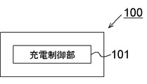
- FIG. 1 is a schematic block diagram showing an example of the charging apparatus according to the first embodiment.
- the charging device 100 is a circuit for charging a secondary battery.
- a lithium ion battery can be used.
- Various types of batteries can be applied to the lithium ion battery.
- positive electrode materials include a cobalt-based positive electrode using lithium cobaltate (LiCoO 2 ), a manganese-based positive electrode using lithium manganate (LiMn 2 O 4 ), and a nickel-based positive electrode using lithium nickelate (LiNiO 2 ). Etc. can be used.
- the negative electrode material, the electrolyte material, and the separator material are not limited.
- As the negative electrode material for example, graphite can be used.
- the secondary battery may be a single cell or may be at least one battery pack in which a plurality of cells are connected in series so as to obtain a predetermined voltage.
- the secondary battery has a plurality of battery packs, the plurality of battery packs may be connected in parallel or in series.
- the secondary battery to which the charging device 100 is applied is not limited to a lithium ion battery.
- the charging device 100 may be applied to a nickel metal hydride battery that uses a hydrogen storage alloy. In the following embodiments, charging of a lithium ion battery will be described as an example.
- the charging device 100 includes a charging control unit 101 that controls charging of the secondary battery.
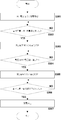
- FIG. 2 shows a flowchart for explaining the operation of the charging apparatus according to the first embodiment, the charging method for the secondary battery, the program for operating the charging apparatus, and the program for controlling the charging method.
- the charging control unit 101 charges the secondary battery with the first current value (S101; first constant current charging step). In response to detecting that the voltage of the secondary battery has reached a predetermined first voltage value, the charging control unit 101 switches to charging at a second current value lower than the first current value ( S103; second constant current charging step). In response to detecting that the voltage of the secondary battery has reached the second voltage value, the charging control unit 101 stops charging (S104, S105).
- the first current value and the second current value are preferably set such that a value obtained by dividing the first current value by the second current value (denoted as “current ratio”) is 1.2 or more.
- the current ratio is preferably set to 6.5 or less. This is because if the first current value is too high, the risk of deposition of dangerous substances increases. In particular, when charging in a low temperature environment, the risk becomes higher. Moreover, it is because charge time will become long if a 2nd electric current value is made too low. Furthermore, the higher the first current value in the first constant current charging step, the greater the voltage drop due to internal resistance that occurs when switching from the first constant current charging step to the second constant current charging step. This voltage drop equivalent is compensated for in the second constant current charging step.
- the current ratio is more preferably 1.5 or more, more preferably 2.3 or more, and further preferably 2.7 or more.
- the current ratio is more preferably 5.9 or less, more preferably 5.4 or less, and further preferably 3.5 or less.
- the current ratio can also be calculated from the charge rate (for example, what is defined in International Electrotechnical Commission (IEC) 61434; It).
- the first current value is preferably a current value of 0.1 It or more when converted to a charge rate corresponding to the charging current. This is to shorten the charging time.
- the first current value is preferably a current value that is more preferably 0.2 It or more, and even more preferably 0.25 It or more.
- the first current value is preferably a current value such that the charge rate is 0.6 It or less. This is to reduce the voltage drop amount.
- the first current value is more preferably a current value at which the charge rate is more preferably 0.5 or less, and even more preferably 0.4 or less.
- the second current value is preferably a current value such that the charge rate is 0.18 It or less. This is because, in a low-temperature environment, for example, in an environment corresponding to a temperature range of 0 ° C. or lower, when the voltage of the secondary battery is high, increasing the charging current increases the risk of hazardous substance deposition.
- the second current value is more preferably a current value such that the charging rate is more preferably 0.15 It or less, and still more preferably 0.1 It or less.
- the second current value is preferably a current value such that the charging rate is 0.04 It or more. This is because if the charging rate of the second current value is set too low, the charging time becomes long.
- the second current value is more preferably a current value such that the charging rate is more preferably 0.05 It or more, and even more preferably 0.06 It or more.
- the first voltage value is preferably set to 4.05 V or less. This is because, in a low temperature environment (for example, less than 0 ° C.), if the battery is charged to a voltage exceeding 4.05 V with a high charging current, the risk of deposition of dangerous substances increases.
- the first voltage value is more preferably 4.04 V or less, and further preferably 4.03 V or less.
- the first voltage value is preferably set to 3.80V or higher. This is because if the first voltage value is set too low, the charging time will be long.
- the first voltage value is more preferably 3.85V or more, and further preferably 3.90V or more.
- the second voltage value is preferably set to 4.2 V or less. This is because, in a low-temperature environment (for example, less than 0 ° C.), the risk of depositing dangerous substances increases when charged to the rated voltage.
- the second voltage value is more preferably 4.15V or less, and further preferably 4.1V or less.
- the constant current charging step is divided into at least two stages.
- the current value in the second constant current charging step in the second stage is lower than the current value in the first constant current charging step in the first stage.
- the charging time can be shortened by selecting a high current value.
- the first current value should not be set too high, and the second current value lower than the first current value before the first current value becomes the voltage of the secondary battery where the risk of deposition of dangerous substances becomes high.
- the risk of deposition of dangerous substances can be reduced. Thereby, even if it is the charge in the winter night in a cold region, both safety
- FIG. 3 shows a flowchart for explaining the operation of the charging device, the charging method of the secondary battery, the program for operating the charging device, and the program for controlling the charging method according to the second embodiment.
- a constant voltage charging step is added to the first embodiment.
- S201 to S204 are the same as S101 to S104 of the first embodiment.
- the charging control unit 101 In response to detecting that the voltage of the secondary battery has reached the second voltage value, the charging control unit 101 performs charging at the second voltage value (S205; constant voltage charging step). In response to detecting that the charging current has reached a predetermined current value, the charging control unit 101 stops charging (S206, S207).
- the battery capacity can be further increased.
- FIG. 4 shows a flowchart for explaining the operation of the charging apparatus according to the third embodiment, the charging method of the secondary battery, the program for operating the charging apparatus, and the program for controlling the charging method.
- switching from the first constant current charging step to the second constant current charging step is determined based on whether or not the voltage of the secondary battery has reached a predetermined voltage value.
- switching from the first constant current charging step to the second constant current charging step is determined based on whether or not the battery capacity of the secondary battery has reached a predetermined value.
- S301 is the same as S101 of the first embodiment.
- the charging control unit 101 switches to charging at a second current value lower than the first current value. (S303; second constant current charging step).
- S303 to S307 are the same as S203 to S207 in the second embodiment.
- the first current value and the second current value can be set similarly to the first embodiment.
- the first capacity value is preferably 20% or more. If the first capacity value is less than 20%, the second constant current charging step will take a long time.
- the first capacity value is preferably 67% or less. If the first capacity value is greater than 67%, the risk of deposition of dangerous substances increases in a low temperature environment. Therefore, by setting the first capacity value within the above range, the total charging time can be shortened and safety can be ensured.
- the first capacity value is more preferably 26% or more, more preferably 40% or more, and further preferably 48% or more.
- the first capacity value is more preferably 64% or less, and further preferably 61% or less.
- the third embodiment has been described based on the second embodiment, the third embodiment can also be applied to the first embodiment. In this case, S305 and 306 in FIG. 4 can be omitted.
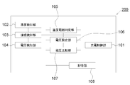
- FIG. 5 is a schematic block diagram showing an example of the charging apparatus according to the fourth embodiment.
- the charging device 200 according to the fourth embodiment is a more preferable form of the charging device according to the first embodiment.
- the charging device 200 detects the presence or absence of a connection between the temperature detection unit 102 that detects a battery-related temperature related to the secondary battery, and the charging power source and the secondary battery.
- a connection detection unit 103 that detects the voltage of the secondary battery, and a voltage detection unit 104 that detects the voltage of the secondary battery.
- the charging device 200 is set with a voltage setting unit 106 that sets a voltage related to the charging control of the secondary battery, and a temperature range determination unit 105 that determines the temperature range of the temperature detected by the temperature detection unit 102.
- a voltage comparison unit 107 that compares the voltage value with the voltage of the secondary battery, and a storage unit 108 that stores various data are further provided.
- the storage unit 108 includes, for example, an upper limit voltage value corresponding to a temperature range, a temperature range during charging, a charging current value during constant current charging, a voltage value during constant voltage charging, a charging end current value during constant voltage charging, and a charging start voltage value. Memorize etc. Note that the charging device 200 may not include all the above-described units.
- the connection detection unit 103 can be configured to output the detected connection information to at least the temperature detection unit 102 and the voltage detection unit 104.
- the temperature detection unit 102 can be configured to detect a battery-related temperature based on connection information from the connection detection unit 103.
- the temperature detection unit 102 can be configured to output the detected temperature information to at least one of the temperature range determination unit 105, the charge control unit 101, and the voltage setting unit 106.
- the voltage detection unit 104 can be configured to detect the voltage of the secondary battery based on the connection information from the connection detection unit 103.
- the voltage detection unit 104 can be configured to output at least the detected voltage information to the voltage comparison unit 107.
- the temperature range determination unit 105 can be configured to determine the temperature range of the battery-related temperature based on the temperature information from the temperature detection unit 102.
- the temperature range determination unit 105 can be configured to output the determined temperature range information to at least one of the charge control unit 101 and the voltage setting unit 106.
- the voltage setting unit 106 can be configured to set the upper limit value of the voltage of the secondary battery based on the temperature range information from the temperature range determination unit 105.
- the voltage setting unit 106 can be configured to output at least the set upper limit value information to the charge control unit 101.
- the voltage comparison unit 107 can be configured to compare the set value and the voltage value based on the voltage information from the voltage detection unit 104.
- the voltage comparison unit 107 can be configured to output at least the comparison result information to the charge control unit 101.
- the charging control unit 101 can be configured to determine a charging method based on at least one piece of information from each of the above-described units and control charging of the secondary battery.
- the temperature detected by the temperature detection unit 102 is preferably the temperature of any part of the secondary battery. This is because when the lithium ion battery is charged, the temperature of the secondary battery affects the deposition of dangerous substances such as lithium.
- the temperature detected by the temperature detection unit 102 is not limited to the temperature of the secondary battery itself, and may be the temperature of the environment where the secondary battery, the charging device, or a power storage system described later is placed. This is because these environmental temperatures greatly affect the temperature of the secondary battery.
- the temperature detector 102 may detect temperatures at a plurality of locations.
- the temperature detected by the temperature detector is referred to as “battery related temperature”.
- the temperature range to which the battery-related temperature belongs is divided into two or more regions according to the risk of deposition of a hazardous substance such as lithium.
- the temperature range is divided into a first temperature range and a second temperature range. It is preferable to set the first temperature range and the second temperature range so as to be adjacent to each other.
- the boundary of the temperature range can be set arbitrarily.
- the boundary between the first temperature range and the second temperature range is such that, in the first temperature range, when charging is performed under the same conditions as the second temperature range, the risk of deposition of dangerous substances such as lithium is increased. Can be set.
- the upper limit value of the secondary battery during charging is preferably set to separate voltage values for the first temperature range and the second temperature range.
- the upper limit value of the secondary battery during charging in the first temperature range is referred to as a first voltage value
- the upper limit value of the secondary battery during charging in the second temperature range is referred to as a second voltage value.
- the first temperature range can be set to include a region where the battery related temperature is less than ⁇ 10 ° C., preferably less than 0 ° C.
- the second temperature range can be set so as to include a region of 10 ° C. or higher, preferably a region of 0 ° C. or higher.
- the first voltage value can be set within a range of 4.1 V or more and less than 4.15 V.
- the second voltage value can be set in a range of 4.15V to 4.2V.
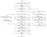
- FIG. 6 shows a flowchart for explaining an operation of the charging device according to the fourth embodiment, a charging method for the secondary battery, and a program for operating the charging device or controlling the charging method.
- the operation and the charging method of the charging device according to the fourth embodiment based on the second embodiment will be described, but the fourth embodiment can also be applied to the first embodiment and the third embodiment. .
- connection detection unit 103 detects whether the secondary battery and the charging power source are electrically connected (S401). For example, in the case of a secondary battery mounted on an electric vehicle, the connection detection unit 103 detects whether the in-vehicle charger and the charging power source are connected. In the case of a secondary battery mounted on a portable device, the connection detection unit 103 detects whether the charger connected to the power source and the portable device are connected. The connection detection unit 103 outputs connection information with the power supply for charging to at least the temperature detection unit 102 and the voltage detection unit 104. The connection detection unit 103 may output the connection information to another unit.
- the temperature detection unit 102 detects at least the battery-related temperature after the connection is confirmed (S402).
- the temperature detection unit 102 outputs temperature information to at least one of the charge control unit 101, the temperature range determination unit 105, and the voltage setting unit 106.
- the temperature detection unit 102 may detect the temperature before connecting the secondary battery and the charging power source. Regardless of whether charging or stopping charging, the temperature detection unit 102 may continue the detection with an interval by separating the battery-related temperatures in terms of time. In FIG. 6, temperature detection after S402 is not shown.
- the temperature range determination unit 105 in response to the temperature information from the temperature detection unit 102, the temperature range determination unit 105 refers to the storage unit 108 and determines to which temperature range the battery-related temperature belongs (S403).
- the temperature range determination unit 105 may determine the temperature range based on an instantaneous temperature, or may determine the temperature range based on a temperature for a certain period or an average temperature. For example, the temperature range determination unit 105 may determine the temperature range based on one piece of temperature information, or may determine the temperature range based on a plurality of temperature information for a predetermined period.
- the storage unit 108 stores in advance the correspondence between temperature and temperature range.
- the temperature range determination unit 105 outputs the determined temperature range information to the voltage setting unit 106.
- the voltage setting unit 106 in response to the temperature range information from the temperature range determination unit 105, refers to the storage unit 108 and sets the upper limit value of the secondary battery voltage to a voltage value corresponding to the temperature range. .
- the storage unit 108 stores the correspondence relationship between the temperature range and the upper limit voltage in advance.
- the voltage setting unit 106 sets the upper limit voltage to the second voltage value when the detected temperature belongs to the first temperature range (S404).
- the upper limit voltage is set to the third voltage value (S415).
- the storage unit 108 stores the set upper limit voltage value.
- the voltage setting unit 106 outputs the set upper limit value information to the voltage comparison unit 107 and the charging control unit 101.
- the voltage detection unit 104 detects the voltage value of the secondary battery in response to the connection information from the connection detection unit 103. It is preferable that the voltage detection unit 104 detects the battery voltage after connection with the charging power source with a time interval. The voltage detection unit 104 outputs voltage value information of the detected secondary voltage to the voltage comparison unit 107.
- the voltage comparison unit 107 compares the battery voltage value with the set upper limit value (S405, S416).
- the voltage comparison unit 107 outputs comparison result information to the charge control unit 101.
- the charge control unit 101 When the battery voltage value is lower than the upper limit value in response to the comparison result information from the voltage comparison unit 107, the charge control unit 101 starts charging the secondary battery. In a state where the battery-related temperature belongs to the first temperature range, the charging control unit 101 charges with the first current value (S406). In a state where the battery-related temperature belongs to the second temperature range, the charging control unit 101 charges with the third current value (S417).
- the third current value a suitable numerical value can be selected as appropriate as long as no dangerous substance is deposited. For example, the third current value can be set higher than the first current value in order to shorten the charging time.
- the charging control unit 101 uses the predetermined first voltage value or third voltage value as the upper limit value of the battery voltage.
- the secondary battery may be charged.
- the charging start voltage value can be set to a voltage value different from the upper limit value.
- the charging start voltage value is set to a voltage value lower than the second voltage value or the third voltage value, and the storage unit 108 stores the charging start voltage value.
- the voltage comparison unit 107 compares the battery voltage value with the charge start voltage value.
- the charge control part 101 starts charge, when a battery voltage value is less than the said charge start voltage value. Even if the battery voltage value is less than the first voltage value or the third voltage value, the charging control unit 101 does not start charging when the battery voltage value is equal to or higher than the charging start voltage value.
- the voltage detection step and the voltage comparison step may be performed before the temperature detection step.
- S406 to S412 are the same as S201 to S207 in the second embodiment.
- S418 to S420 are the same as S409 to S412 except that the upper limit voltage value and the charging current value are different.
- the charging control unit 101 charges the secondary battery with the second current value in response to the comparison result information. Is started (S413, S414). The subsequent steps are the same as S409 to S412.
- the same effect as that of the first embodiment can be obtained. Further, the battery capacity can be further increased according to the state of the battery-related temperature.
- FIG. 7 the schematic block diagram which shows an example of the charging device which concerns on 5th Embodiment is shown.
- the charging device 300 according to the fifth embodiment is a more preferable form of the charging device according to the first embodiment.
- the charging device 300 compares the battery capacity calculation unit 109 that calculates the battery capacity of the secondary battery, and compares the battery capacity value of the secondary battery with a preset first capacity value. And a battery capacity comparison unit 110 for performing.
- the charge control unit 101 can be configured to output the charge control information to the battery capacity calculation unit 109. Examples of the charging control information include a charging current value and a charging time.
- the voltage detection unit 104 can be configured to output voltage information to the battery capacity calculation unit 109.
- the battery capacity calculation unit 109 can be configured to calculate the battery capacity of the secondary battery based on the charge control information from the charge control unit 101 and the voltage information from the voltage detection unit 104.
- the battery capacity calculation unit 109 can be configured to output battery capacity information to the battery capacity comparison unit 110.
- the battery capacity comparison unit 110 may be configured to compare a predetermined battery capacity standard value of the secondary battery with the battery capacity of the secondary battery based on the battery capacity information from the battery capacity calculation unit 109. it can.
- the battery capacity comparison unit 110 can be configured to output the comparison result information to the charge control unit 101.
- the battery capacity comparison unit 110 can be configured to output the comparison result information to the voltage comparison unit 107.
- the charging control unit 101 can be configured to charge the secondary battery based on the comparison result information from the battery capacity comparison unit 110.
- FIG. 8 shows a flowchart for explaining the operation of the charging apparatus according to the fifth embodiment, the charging method of the secondary battery, and the program for operating the charging apparatus or controlling the charging method.
- the operation of the charging apparatus and the charging method according to the fifth embodiment based on the third and fourth embodiments will be described.
- S501 to S504 and S513 to S520 are the same as S401 to S404 and S413 to S420 in the fourth embodiment.
- the charging control unit 101 starts charging the secondary battery in response to the comparison result information from the battery capacity comparison unit 110.
- the charging control unit 101 starts charging at the first current value (S505, S506).
- the charging current is switched from the first current value to the second current value in response to the comparison result information from the battery capacity comparison unit 110 (S507). , S508).
- S508 to S512 are the same as S408 to S412 in the fourth embodiment.
- the calculation of the battery capacity by the battery capacity calculation unit 109 is not limited to before and after the temperature range determination by the temperature range determination unit 105.
- the voltage comparison unit 107 responds to the comparison result information from the battery capacity comparison unit 110. Then, the voltage value of the secondary battery is compared with the second voltage value.
- S513, S514, and S512 are the same as S413, S414, and S412 in the fourth embodiment.
- the same effect as in the first embodiment can be obtained. Further, the battery capacity can be further increased according to the state of the battery-related temperature.
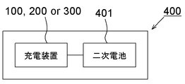
- FIG. 9 is a schematic diagram illustrating an example of a power storage system according to the sixth embodiment.
- the power storage system 400 includes a secondary battery 401 having at least one cell, and at least one of the charging devices 100, 200, and 300 according to the embodiment connected to the secondary battery 401.
- a charging power source is detachably connected to charging devices 100, 200, and 300.
- Charging devices 100, 200, and 300 charge secondary battery 401.
- the charging method by the power storage system 400 is the same as the charging method described above.
- FIG. 10 is a schematic diagram illustrating an example of a power storage system according to the seventh embodiment.
- the power storage system 500 includes a temperature sensor 402 connected to the charging devices 100, 200, and 300 in addition to the power storage system according to the sixth embodiment.
- the temperature sensor 402 is a sensor that detects the battery-related temperature described above.
- the temperature sensor 402 can be installed, for example, so as to detect the temperature of at least one of cell surfaces, cells, and conductors connected to the cells.
- the temperature sensor 402 may be installed to detect the temperature of the environment where the secondary battery 401, the charging devices 100 and 200, or the power storage system 300 is placed, for example.
- a plurality of temperature sensors 402 may be installed so as to detect temperatures at a plurality of locations.
- the charging method by the power storage system 500 is the same as the charging method described above.
- the power storage system 500 can be applied to an embodiment that requires temperature determination. According to the seventh embodiment, the same effect as in the first embodiment can be obtained. Moreover, according to 7th Embodiment, charge according to battery related temperature can be implemented. For example, according to the battery-related temperature, it can be charged while ensuring safety, and can be charged to an appropriate voltage value.
- FIG. 11 is a schematic diagram illustrating an example of a power storage system according to the eighth embodiment.
- the power storage system 600 according to the tenth embodiment is a preferred form of the power storage system according to the seventh embodiment.
- the power storage system 600 is based on the seventh embodiment, but may be based on the sixth embodiment. In this case, the power storage system may not include the temperature sensor.
- the power storage system 600 includes a secondary battery 401 having at least one cell, a battery management unit (BMU) 403 that performs charge control and discharge control of the secondary battery 401, and protection management of the secondary battery 401, Power conditioner (PCS) 404 that performs conversion of DC power and AC power between the secondary battery 401 and the power source and load, voltage and frequency adjustment, and control and monitoring of the BMU 403 and PCS A system controller (SC) 405 to be executed.
- the BMU 403, the PCS 404, and the SC 405 are connected so that they can communicate with each other.
- a charging power source is connected to the PCS 404.
- PCS and SC are illustrated as separate elements, but the illustrated form includes a form in which PCS and CS are incorporated into one element.
- the charging devices 100 and 200 according to the above embodiment are incorporated in the BMU 403.
- the secondary battery 401 and the temperature sensor 402 are connected to the charging devices 100 and 200.
- the program can be incorporated into SC405, for example.
- the program causes the charging device to execute the operation of each unit and each step of the charging method.
- the configuration of the eighth embodiment other than the above is the same as that of the seventh embodiment.
- the program can be realized by making the operation or each step of each part in each of the above embodiments be each process of the program.
- a lithium ion battery was manufactured, charged using the charging device and the charging method according to the second embodiment, the required charging time was measured, and the presence or absence of hazardous substances was confirmed.
- FIG. 12 (a) are schematic views for explaining a method for manufacturing a lithium ion battery.
- the positive electrode 14 and the negative electrode 15 produced above were alternately laminated with the separator 13 interposed therebetween (FIG. 12 (a)) to produce a laminate 6 (FIG. 12 (b)).
- the separator 13 is an insulating material such as polyolefin, and has the same shape as the positive electrode 14 and the negative electrode 15.
- the dimensions of the main surface of the laminate 6 were 200 mm long and 100 mm wide.
- 30 layers of the positive electrode 14 and 31 layers of the negative electrode 15 were laminated. Then, a positive electrode current collecting tab was connected to the positive electrode 14.
- a negative electrode current collecting tab was connected to the negative electrode 15 (FIG. 12B).
- the positive electrode current collecting tab and the negative electrode current collecting tab were drawn from one side of the laminate 6 in a plan view and laminated so as not to interfere with each other.
- a battery element fixing member 8 that holds the separator 13, the positive electrode 14, and the negative electrode 15 so as not to be displaced is provided on a pair of sides from which the positive current collecting tab and the negative current collecting tab are not drawn (FIG. 12). (C)).
- the plurality of positive electrode current collecting tabs drawn from one side of the laminate 6 were bundled into one, and the plurality of bundled positive electrode current collecting tabs and one end of the positive electrode terminal 16 were connected. Similarly, a plurality of negative electrode current collecting tabs were bundled together and connected to one end of the negative electrode terminal 17 (FIG. 13).
- the produced laminated body 6 was coated on the front and back surfaces with a resin and accommodated in an exterior body 7 made of flexible aluminum (FIG. 14A). The other end of the positive electrode terminal 16 and the other end of the negative electrode terminal 17 were exposed to the outside of the exterior body 7.
- the other end of the positive electrode terminal 16 and the other end of the negative electrode terminal 17 exposed to the outside of the outer package 7 become a positive electrode terminal exposed portion 23 and a negative electrode terminal exposed portion 24.
- the periphery of the exterior body 7 other than the opening for pouring the electrolytic solution was sealed by heat welding. Thereafter, an electrolytic solution was injected into the exterior body 7 from the opening, and the opening was bonded and sealed to produce a lithium ion battery 3 (FIG. 14B).
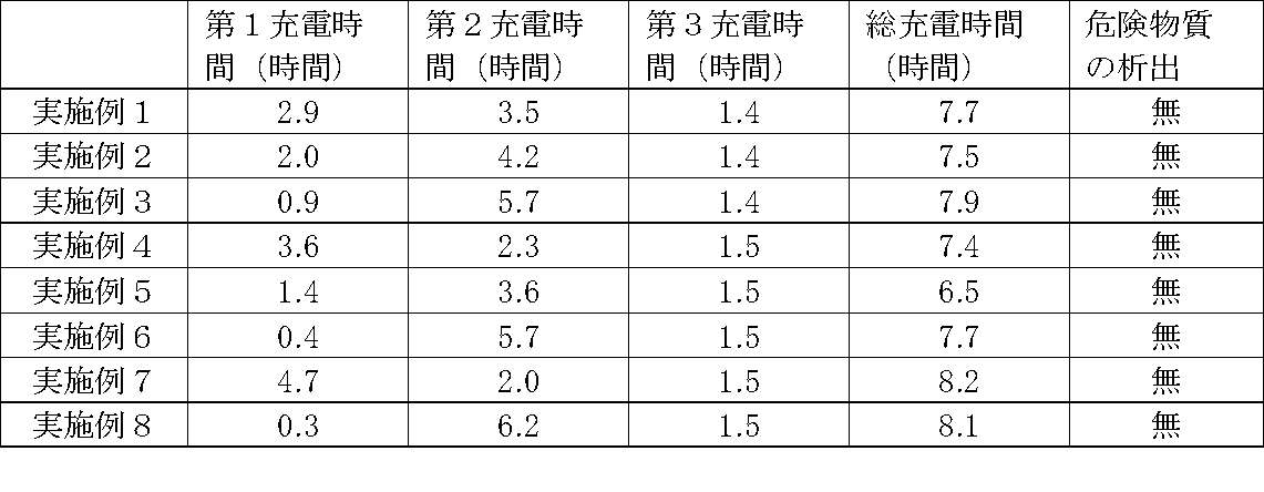
- Table 1 shows the value obtained by converting the first current value into the charge rate as the first charge rate.
- a value obtained by converting the second current value into the charge rate is shown as the second charge rate.
- the “rate ratio” shown in Table 1 is a value obtained by dividing the first charging rate value by the second charging rate value.
- the remaining battery capacity at the time when the first constant current charging step is completed is indicated as SOC (State of Charge).
- SOC is the ratio of the battery capacity to the rated capacity of the battery.
- the first charging time is the time required for the first constant current charging step.
- the second charging time is the time required for the second constant current charging step.
- the third charging time is the time required for the constant voltage charging step.
- Examples 1 to 8 precipitation of dangerous substances such as lithium was not confirmed. Under the current implementation conditions, when charging to the upper limit voltage value at the first charge rate, it is considered that, as a rule of thumb, lithium may have precipitated. However, in Examples 1 to 8, it is considered that the dangerous substance did not precipitate because the charging current was decreased from the first charging rate to the second charging rate and charged to the upper limit voltage value. According to Examples 1 to 8, it is considered that the safety can be further improved when the second charging rate is 0.1 It or less. However, the charge rate at which no hazardous substance is deposited is not limited to this range.
- the total charging time could be about 8 hours. Under the current implementation conditions, when charging from the start of charging to the upper limit voltage value at the second charging rate, the total charging time is considered to have greatly exceeded 8 hours. However, since charging was started at a first charging rate higher than the second charging rate, it is considered that the total charging time could be shortened. According to Examples 1 to 8, the total charge time can be suppressed to 8.2 hours or less by setting the charge rate to 1.3 or more and 6.4 or less, and the charge rate is 1.6 or more and 5.8 or less. The total charging time could be reduced to less than 8 hours. The reason why the charging time in Example 7 is longer than that in Examples 1 to 6 is considered to be that the first charging rate was lower than in Examples 1 to 6.
- Example 8 the charging time is longer than that in Examples 1 to 6 because the first charging rate is higher than in Examples 1 to 6, so that the first constant current charging step to the second constant current charging step is performed. This is presumably because the voltage drop at the time of switching increased and it took time to compensate for the increase at the second charge rate.
- the voltage value for switching from the first constant current charging step to the second constant current charging step is set to 4.03 V.
- the voltage value to be switched is not limited to this voltage value. .
- the total charging time can be suppressed to 8.2 hours or less, and is 27% or more and 63% or less.
- the total charge time could be less than 8 hours.
- Hours of low electricity unit price are often set to 8 hours (for example, from 11:00 pm to 7:00 am the next day). Therefore, according to the first to eighth embodiments, the charging can be almost completed in the time zone where the power unit price is low, and the power cost can be reduced.
- the charging device, the power storage system, the charging method, and the program of the present invention have been described based on the above embodiment, but are not limited to the above embodiment, and are within the scope of the present invention and the basic of the present invention.
- Various modifications, changes, and improvements may be included in various disclosed elements (including each element of each claim, each element of each embodiment or example, each element of each drawing, etc.) based on the technical idea. Needless to say, it can be done.
- Various combinations and replacements of various disclosed elements including each element of each claim, each element of each embodiment or example, each element of each drawing, etc. within the scope of the entire disclosure of the present invention. Selection is possible.
- a charging device Charging the secondary battery with a first current value until the voltage of the secondary battery reaches a predetermined first voltage value, and in response to detecting that the voltage has reached the first voltage value,
- a charging device comprising a charge control unit that performs control to charge the secondary battery until a predetermined second voltage value is reached at a second current value lower than the first current value.
- the secondary battery is a lithium ion battery,
- the charging device in which the first voltage value is 3.80V or more and 4.05V or less.
- the secondary battery is charged with a first current value until the battery capacity of the secondary battery reaches a predetermined first capacity value, and in response to detecting that the battery capacity has reached the first capacity value.
- a charging control unit that performs control to charge the secondary battery until the voltage of the secondary battery reaches a predetermined charging voltage value at a second current value lower than the first current value; apparatus.
- the first capacity value is 20% or more and 67% or less.
- the charging control unit moves the secondary battery until the charging current value reaches a predetermined third current value.
- a charging device for charging at the second voltage value or the charging voltage value is
- a charging device in which a value obtained by dividing the first current value by the second current value is 1.4 or more and 6.5 or less.
- the charging device wherein the first current value is a current value corresponding to a charging rate of 0.1 It or more and 0.6 It or less.
- a temperature detection unit for detecting a temperature related to the secondary battery; In response to temperature information from the temperature detection unit that has detected a temperature of 0 ° C. or less, the charging control unit controls charging of the secondary battery.
- the temperature is at least one of the temperature of any part of the secondary battery, the temperature of the environment where the secondary battery is placed, and the temperature of the environment where the charger is placed. .
- Appendix 12 The charging device of appendices 1-11; An electrical storage system comprising: the secondary battery connected to the charging device.
- a power storage system further comprising a temperature sensor connected to the charging device and detecting a temperature related to the secondary battery.
- a battery management unit for managing charge and discharge of the secondary battery is a power storage system including the charging device.
- a power conditioner for connecting the secondary battery and a charging power source;
- a system controller for controlling the battery management unit and the power conditioner;
- the battery management unit, the power conditioner, and the system controller are connected to each other.
- the secondary battery is a lithium ion battery, The charging method wherein the first voltage value is 3.80V or more and 4.05V or less.
- the temperature is at least one of the temperature of any part of the secondary battery, the temperature of the environment where the secondary battery is placed, and the temperature of the environment where the charging device for charging the secondary battery is placed. Charging method which is one temperature.
- the charging device, power storage system, charging method, and program of the present invention can be suitably applied to charging a secondary battery, particularly a lithium ion battery.
- a secondary battery particularly a lithium ion battery.
- the present invention can be suitably applied to automobiles, portable devices, electric motors, portable power sources, and the like equipped with secondary batteries.
Landscapes
- Engineering & Computer Science (AREA)
- Power Engineering (AREA)
- Manufacturing & Machinery (AREA)
- Chemical & Material Sciences (AREA)
- Chemical Kinetics & Catalysis (AREA)
- Electrochemistry (AREA)
- General Chemical & Material Sciences (AREA)
- Secondary Cells (AREA)
- Charge And Discharge Circuits For Batteries Or The Like (AREA)
Abstract
Description
本発明は、日本国特許出願:特願2013-228669号(2013年11月 1日出願)に基づくものであり、同出願の全記載内容は引用をもって本書に組み込み記載されているものとする。
本発明は、二次電池を充電するための充電装置に関する。本発明は、当該充電装置を備える蓄電システムに関する。本発明は、二次電池を充電する充電方法に関する。また、本発明は、当該充電装置を動作させるプログラムないし当該充電方法を制御するプログラムに関する。
正極電極の作製について説明する。LiMn2O4を85質量%、導電補助材としてアセチレンブラックを7質量%、及びバインダーとしてポリフッ化ビニリデンを8質量%混合した。この混合物に、N-メチルピロリドンを加えてさらに混合し、正極スラリーを作製した。これをドクターブレード法により、集電体となる厚さ20μmのAl箔の両面にロールプレス処理後の厚さが160μmになるように塗布し、120℃で5分間乾燥・プレス工程を経て正極活物質両面塗布部を形成した。なお、正極の一方の端部にはいずれの面にも正極活物質が塗布されていない正極活物質非塗布部を設けた。
負極電極の作製について説明する。黒鉛を90質量%、導電補助剤としてアセチレンブラックを1質量%、及びバインダーとしてポリフッ化ビニリデンを9質量%混合した。この混合物に、N-メチルピロリドンを加えてさらに混合し負極スラリーを作製した。これを集電体となる厚さ10μmのCu箔の両面にロールプレス処理後の厚さが120μmとなるように塗布し、120℃で5分間乾燥・プレス工程を経て負極活物質両面塗布部を形成した。なお、負極の一方の端部に、負極活物質が塗布されていない負極活物質非塗布部を設けた。
電解液の作製について説明する。エチレンカーボネート(EC)/ジエチルカーボネート(DEC)=30/70(体積比)からなるカーボネート系非水電解液を99質量部と、ビニレンカーボネートを1質量部(ビニレンカーボネートの含有率:1質量%)とを混合した。この混合物に、さらに、支持塩としてのLiPF6を1.0モル/lの濃度で溶解して、電解液を得た。
リチウムイオン電池の作製について説明する。図12~図14に、リチウムイオン電池の作製方法を説明するための概略図を示す。上記で作製した正極電極14と負極電極15とを、セパレータ13を挟んで交互に積層し(図12(a))、積層体6を作製した(図12(b))。セパレータ13は、ポリオレフィン等の絶縁性を有する材料であり、正極電極14及び負極電極15と同じ形状を有する。積層体6の主面の寸法は、縦200mm、横100mmであった。積層体6には、正極電極14を30層、負極電極15を31層積層した。そして、正極電極14に正極集電タブを接続した。負極電極15に負極集電タブを接続した(図12(b))。正極集電タブ及び負極集電タブは、平面的にみて、積層体6の一辺から引き出し、それぞれ干渉しないように積層した。正極集電タブ及び負極集電タブが引き出されていない一対の辺に、積層されたセパレータ13、正極電極14及び負極電極15がずれないように保持する電池要素固定部材8を設けた(図12(c))。
上記で作製したリチウムイオン電池を表1に記載の条件で充電し、第1定電流充電ステップ及び第2定電流充電ステップにおける充電時間を測定した。また、危険物質の析出の有無を確認した。危険物質の析出は、目視による確認及び釘刺し試験と呼ばれる安全性試験により確認した。充電は-10℃の条件下で実施した。充電に使用するリチウムイオン電池は、放電処理によって電圧3Vに調整したものを使用した。第1定電流充電ステップにおいては、第1電圧値4.03Vに達するまで第1電流値でリチウムイオン電池を充電した。その後、第2電圧値4.10Vに達するまで第2電流値でリチウムイオン電池を充電した。その後、定電圧ステップにおいて、第2電圧値4.10Vで充電電流値に対応する充電レートが0.03Itに達するまでリチウムイオン電池を充電した。実施例1~8の結果を表2に示す。

二次電池の電圧が予め定められた第1電圧値に達するまで第1電流値で前記二次電池の充電を行い、前記電圧が前記第1電圧値に達したことの検出に応じて、前記第1電流値よりも低い第2電流値で、予め定められた第2電圧値となるまで前記二次電池を充電する制御を行う充電制御部を備えている充電装置。
前記二次電池はリチウムイオン電池であり、
前記第1電圧値は3.80V以上4.05V以下である充電装置。
二次電池の電池容量が予め定められた第1容量値に達するまで第1電流値で前記二次電池の充電を行い、前記電池容量が前記第1容量値に達したことの検出に応じて、前記第1電流値よりも低い第2電流値で、前記二次電池の電圧が予め定められた充電電圧値となるまで前記二次電池を充電する制御を行う充電制御部を備えている充電装置。
前記第1容量値は20%以上67%以下である充電装置。
前記充電制御部は、前記電圧が前記第2電圧値又は前記充電電圧値に達したことの検出に応じて、充電電流値が予め定められた第3電流値となるまで前記二次電池を前記第2電圧値又は前記充電電圧値で充電する充電装置。
前記第1電流値を前記第2電流値で除した値が1.4以上6.5以下である充電装置。
前記第2電流値は、0.18It以下の充電レートに対応した電流値である充電装置。
前記第1電流値は、0.1It以上0.6It以下の充電レートに対応した電流値である充電装置。
前記二次電池に関連する温度を検知する温度検知部をさらに備え、
0℃以下の温度を検知した前記温度検知部からの温度情報に応答して、前記充電制御部は前記二次電池の充電を制御する充電装置。
前記温度は、前記二次電池のいずれかの部分の温度、前記二次電池が置かれた環境の温度、及び前記充電装置が置かれた環境の温度のうちの少なくとも1つの温度である充電装置。
前記二次電池はリチウムイオン電池である充電装置。
付記1~11の充電装置と、
前記充電装置に接続された前記二次電池と、を備える蓄電システム。
前記充電装置に接続され、二次電池に関連する温度を検知する温度センサをさらに備える蓄電システム。
前記二次電池の充電及び放電を管理する電池管理ユニットをさらに備え、
前記電池管理ユニットは前記充電装置を備えている蓄電システム。
前記二次電池と充電用電源を接続するためのパワーコンディショナと、
前記電池管理ユニット及び前記パワーコンディショナを制御するシステムコントローラと、をさらに備え、
前記電池管理ユニット、前記パワーコンディショナ及び前記システムコントローラは相互に接続されている蓄電システム。
付記に記載の充電装置を動作させるプログラム。
二次電池の電圧が予め定められた第1電圧値に達するまで第1電流値で前記二次電池の充電を行う工程と、
前記電圧が前記第1電圧値から、予め定められた第2電圧値に達するまで、前記第1電流値よりも低い第2電流値で前記二次電池を充電する工程と、を含む充電方法。
前記二次電池はリチウムイオン電池であり、
前記第1電圧値は3.80V以上4.05V以下である充電方法。
二次電池の電池容量が予め定められた第1容量値に達するまで第1電流値で前記二次電池の充電を行う工程と、
前記電池容量が前記第1容量値に達した状態に対応する前記二次電池の第1電圧値から、前記二次電池の電圧が予め定められた第2電圧値に達するまで、前記第1電流値よりも低い第2電流値で前記二次電池を充電する工程と、を含む充電方法。
前記第1容量値は20%以上67%以下である充電方法。
前記電圧が前記第2電圧値に達した状態において、充電電流が予め定められた第1電流値以下となるまで前記第2電圧値で前記二次電池の充電を行う工程と、をさらに含む充電方法。
前記第1電流値を前記第2電流値で除した値が1.4以上6.5以下である充電方法。
前記第2電流値は、0.18It以下の充電レートに対応した電流値である充電方法。
前記第1電流値は、0.1It以上0.6It以下の充電レートに対応した電流値である充電方法。
前記二次電池に関連する温度が0℃以下の温度範囲において行う充電方法。
前記温度は、前記二次電池のいずれかの部分の温度、前記二次電池が置かれた環境の温度、及び前記二次電池を充電する充電装置が置かれた環境の温度のうちの少なくとも1つの温度である充電方法。
前記二次電池はリチウムイオン電池である充電方法。
付記に記載の充電方法を制御するためのプログラム。
付記に係る充電装置を備える自動車。
付記に係る蓄電システムを備える自動車。
付記に係る充電装置を備える電動機。
付記に係る蓄電システムを備える電動機。
付記に係る充電装置を備える携帯機器。
付記に係る蓄電システムを備える携帯機器。
付記に係る充電装置を備える携帯電源。
付記に係る蓄電システムを備える携帯電源。
6 積層体
7 外装体
8 電池要素固定部材
13 セパレータ
14 正極電極
15 負極電極
16 正極端子
17 負極端子
23 正極端子露出部
24 負極端子露出部
100,200,300 充電装置
101 充電制御部
102 温度検知部
103 接続検知部
104 電圧検知部
105 温度範囲判定部
106 電圧設定部
107 電圧比較部
108 記憶部
109 電池容量算出部
110 電池容量比較部
400,500,600 蓄電システム
401 二次電池
402 温度センサ
403 電池管理ユニット
404 パワーコンディショナ
405 システムコントローラ
Claims (28)
- 二次電池の電圧が予め定められた第1電圧値に達するまで第1電流値で前記二次電池の充電を行い、前記電圧が前記第1電圧値に達したことの検出に応じて、前記第1電流値よりも低い第2電流値で、予め定められた第2電圧値となるまで前記二次電池を充電する制御を行う充電制御部を備えている、ことを特徴とする充電装置。
- 前記二次電池はリチウムイオン電池であり、
前記第1電圧値は3.80以上4.05V以下である、ことを特徴とする請求項1に記載の充電装置。 - 二次電池の電池容量が予め定められた第1容量値に達するまで第1電流値で前記二次電池の充電を行い、前記電池容量が前記第1容量値に達したことの検出に応じて、前記第1電流値よりも低い第2電流値で、前記二次電池の電圧が予め定められた充電電圧値となるまで前記二次電池を充電する制御を行う充電制御部を備えている、ことを特徴とする充電装置。
- 前記第1容量値は20%以上67%以下である、ことを特徴とする請求項3に記載の充電装置。
- 前記充電制御部は、前記電圧が前記第2電圧値又は前記充電電圧値に達したことの検出に応じて、充電電流値が予め定められた第3電流値となるまで前記二次電池を前記第2電圧値又は前記充電電圧値で充電する、ことを特徴とする請求項1~4のいずれか一項に記載の充電装置。
- 前記第1電流値を前記第2電流値で除した値が1.4以上6.5以下である、ことを特徴とする請求項1~5のいずれか一項に記載の充電装置。
- 前記第2電流値は、0.18It以下の充電レートに対応した電流値である、ことを特徴とする請求項1~3のいずれか一項に記載の充電装置。
- 前記第1電流値は、0.1It以上0.6It以下の充電レートに対応した電流値である、ことを特徴とする請求項7に記載の充電装置。
- 前記二次電池に関連する温度を検知する温度検知部をさらに備え、
0℃以下の温度を検知した前記温度検知部からの温度情報に応答して、前記充電制御部は前記二次電池の充電を制御する、ことを特徴とする請求項1~8のいずれか一項に記載の充電装置。 - 前記温度は、前記二次電池のいずれかの部分の温度、前記二次電池が置かれた環境の温度、及び前記充電装置が置かれた環境の温度のうちの少なくとも1つの温度である、ことを特徴とする請求項1~9のいずれか一項に記載の充電装置。
- 前記二次電池はリチウムイオン電池であることを特徴とする請求項1~10のいずれか一項に記載の充電装置。
- 請求項1~11のいずれか一項に記載の充電装置と、
前記充電装置に接続された前記二次電池と、を備えることを特徴とする蓄電システム。 - 前記充電装置に接続され、二次電池に関連する温度を検知する温度センサをさらに備えることを特徴とする請求項12に記載の蓄電システム。
- 前記二次電池の充電及び放電を管理する電池管理ユニットをさらに備え、
前記電池管理ユニットは前記充電装置を備えていることを特徴とする請求項12又は13に記載の蓄電システム。 - 前記二次電池と充電用電源を接続するためのパワーコンディショナと、
前記電池管理ユニット及び前記パワーコンディショナを制御するシステムコントローラと、をさらに備え、
前記電池管理ユニット、前記パワーコンディショナ及び前記システムコントローラは相互に接続されていることを特徴とする請求項12~14のいずれか一項に記載の蓄電システム。 - 請求項1~11のいずれか一項に記載の充電装置を動作させるプログラム。
- 二次電池の電圧が予め定められた第1電圧値に達するまで第1電流値で前記二次電池の充電を行う工程と、
前記電圧が前記第1電圧値から、予め定められた第2電圧値に達するまで、前記第1電流値よりも低い第2電流値で前記二次電池を充電する工程と、を含む、
ことを特徴とする充電方法。 - 前記二次電池はリチウムイオン電池であり、
前記第1電圧値は3.80V以上4.05V以下である、ことを特徴とする請求項17に記載の充電方法。 - 二次電池の電池容量が予め定められた第1容量値に達するまで第1電流値で前記二次電池の充電を行う工程と、
前記電池容量が前記第1容量値に達した状態に対応する前記二次電池の第1電圧値から、前記二次電池の電圧が予め定められた第2電圧値に達するまで、前記第1電流値よりも低い第2電流値で前記二次電池を充電する工程と、を含む、
ことを特徴とする充電方法。 - 前記第1容量値は20%以上67%以下である、ことを特徴とする請求項19に記載の充電方法。
- 前記電圧が前記第2電圧値に達した状態において、充電電流が予め定められた第1電流値以下となるまで前記第2電圧値で前記二次電池の充電を行う工程と、をさらに含むことを特徴とする請求項17~20のいずれか一項に記載の充電方法。
- 前記第1電流値を前記第2電流値で除した値が1.4以上6.5以下である、ことを特徴とする請求項17~21のいずれか一項に記載の充電方法。
- 前記第2電流値は、0.18It以下の充電レートに対応した電流値である、ことを特徴とする請求項17~22のいずれか一項に記載の充電方法。
- 前記第1電流値は、0.1It以上0.6It以下の充電レートに対応した電流値である、ことを特徴とする請求項23に記載の充電方法。
- 前記二次電池に関連する温度が0℃以下の温度範囲において行う、ことを特徴とする請求項17~24のいずれか一項に記載の充電方法。
- 前記温度は、前記二次電池のいずれかの部分の温度、前記二次電池が置かれた環境の温度、及び前記二次電池を充電する充電装置が置かれた環境の温度のうちの少なくとも1つの温度である、ことを特徴とする請求項25に記載の充電方法。
- 前記二次電池はリチウムイオン電池であることを特徴とする請求項17~26のいずれか一項に記載の充電方法。
- 請求項17~27のいずれか一項に記載の充電方法を制御するためのプログラム。
Priority Applications (3)
| Application Number | Priority Date | Filing Date | Title |
|---|---|---|---|
| JP2015545321A JP6188169B2 (ja) | 2013-11-01 | 2014-10-31 | 充電装置、蓄電システム、充電方法及びプログラム |
| US15/033,616 US10230250B2 (en) | 2013-11-01 | 2014-10-31 | Charging apparatus, electricity storage system, charging method and program |
| EP14857288.6A EP3065258B1 (en) | 2013-11-01 | 2014-10-31 | Charging apparatus, electricity storage system |
Applications Claiming Priority (2)
| Application Number | Priority Date | Filing Date | Title |
|---|---|---|---|
| JP2013228669 | 2013-11-01 | ||
| JP2013-228669 | 2013-11-01 |
Publications (1)
| Publication Number | Publication Date |
|---|---|
| WO2015064735A1 true WO2015064735A1 (ja) | 2015-05-07 |
Family
ID=53004331
Family Applications (1)
| Application Number | Title | Priority Date | Filing Date |
|---|---|---|---|
| PCT/JP2014/079029 Ceased WO2015064735A1 (ja) | 2013-11-01 | 2014-10-31 | 充電装置、蓄電システム、充電方法及びプログラム |
Country Status (4)
| Country | Link |
|---|---|
| US (1) | US10230250B2 (ja) |
| EP (1) | EP3065258B1 (ja) |
| JP (1) | JP6188169B2 (ja) |
| WO (1) | WO2015064735A1 (ja) |
Cited By (3)
| Publication number | Priority date | Publication date | Assignee | Title |
|---|---|---|---|---|
| EP3104490A1 (en) * | 2015-06-08 | 2016-12-14 | Makita Corporation | Battery-charge control device, battery charger, and battery pack |
| JP2019126115A (ja) * | 2018-01-12 | 2019-07-25 | Fdk株式会社 | アルカリ蓄電池の充電制御方法及びアルカリ蓄電池用充電器 |
| JP2020061301A (ja) * | 2018-10-11 | 2020-04-16 | トヨタ自動車株式会社 | 電池の製造方法 |
Families Citing this family (10)
| Publication number | Priority date | Publication date | Assignee | Title |
|---|---|---|---|---|
| JP6536466B2 (ja) * | 2016-04-27 | 2019-07-03 | 株式会社オートネットワーク技術研究所 | 電源装置 |
| TWI625915B (zh) * | 2016-11-18 | 2018-06-01 | Industrial Technology Research Institute | 智慧型充電方法 |
| US20180166888A1 (en) * | 2016-12-13 | 2018-06-14 | Bae Systems Controls Inc. | Managing Battery Charge Status To Provide Safe Operation For Electronic Devices |
| JP6809602B2 (ja) * | 2017-04-14 | 2021-01-06 | 株式会社村田製作所 | 充電装置および充電方法 |
| JP6864536B2 (ja) * | 2017-04-25 | 2021-04-28 | 株式会社東芝 | 二次電池システム、充電方法、プログラム、及び車両 |
| US20190006064A1 (en) * | 2017-06-29 | 2019-01-03 | David R. Hall | Power Drop Assembly |
| WO2020051808A1 (zh) * | 2018-09-12 | 2020-03-19 | Oppo广东移动通信有限公司 | 充电控制方法和装置、电子设备、计算机可读存储介质 |
| CN112448434B (zh) * | 2019-09-03 | 2024-01-30 | 华为技术有限公司 | 一种充电控制方法及充电控制装置 |
| CN112383099A (zh) * | 2020-10-09 | 2021-02-19 | 长城汽车股份有限公司 | 一种确定直流充电电流的方法、装置以及一种汽车 |
| WO2025072884A1 (en) * | 2023-09-27 | 2025-04-03 | Iontra Inc | Method and system for optimal charging process of lithium-ion batteries to mitigate cell degradation in real time |
Citations (5)
| Publication number | Priority date | Publication date | Assignee | Title |
|---|---|---|---|---|
| JPH05336678A (ja) * | 1992-05-30 | 1993-12-17 | Toyo Commun Equip Co Ltd | 充電器の充電制御方法及び回路 |
| JP2008220121A (ja) * | 2007-03-07 | 2008-09-18 | Nagano Japan Radio Co | 充電装置 |
| JP2009022079A (ja) | 2007-07-10 | 2009-01-29 | Sanyo Electric Co Ltd | リチウムイオン二次電池の充電方法 |
| JP2011004509A (ja) * | 2009-06-18 | 2011-01-06 | Panasonic Corp | 充電制御回路、電池パック、及び充電システム |
| WO2011033704A1 (ja) * | 2009-09-18 | 2011-03-24 | パナソニック株式会社 | 非水電解質二次電池の充電方法及び充電装置 |
Family Cites Families (5)
| Publication number | Priority date | Publication date | Assignee | Title |
|---|---|---|---|---|
| JPH0946916A (ja) | 1995-08-02 | 1997-02-14 | Honda Motor Co Ltd | 充電制御装置 |
| KR101222220B1 (ko) * | 2009-09-18 | 2013-01-15 | 파나소닉 주식회사 | 비수 전해질 이차전지의 충전방법 및 충전장치 |
| JP2013192275A (ja) | 2010-07-05 | 2013-09-26 | Konica Minolta Medical & Graphic Inc | 放射線画像撮影装置の充電装置及び放射線画像検出システム |
| JP5089825B2 (ja) | 2011-03-18 | 2012-12-05 | パナソニック株式会社 | 非水電解質二次電池の充電方法、及び電池パック |
| JP5879557B2 (ja) * | 2011-09-12 | 2016-03-08 | パナソニックIpマネジメント株式会社 | 充電器 |
-
2014
- 2014-10-31 WO PCT/JP2014/079029 patent/WO2015064735A1/ja not_active Ceased
- 2014-10-31 JP JP2015545321A patent/JP6188169B2/ja active Active
- 2014-10-31 EP EP14857288.6A patent/EP3065258B1/en active Active
- 2014-10-31 US US15/033,616 patent/US10230250B2/en active Active
Patent Citations (5)
| Publication number | Priority date | Publication date | Assignee | Title |
|---|---|---|---|---|
| JPH05336678A (ja) * | 1992-05-30 | 1993-12-17 | Toyo Commun Equip Co Ltd | 充電器の充電制御方法及び回路 |
| JP2008220121A (ja) * | 2007-03-07 | 2008-09-18 | Nagano Japan Radio Co | 充電装置 |
| JP2009022079A (ja) | 2007-07-10 | 2009-01-29 | Sanyo Electric Co Ltd | リチウムイオン二次電池の充電方法 |
| JP2011004509A (ja) * | 2009-06-18 | 2011-01-06 | Panasonic Corp | 充電制御回路、電池パック、及び充電システム |
| WO2011033704A1 (ja) * | 2009-09-18 | 2011-03-24 | パナソニック株式会社 | 非水電解質二次電池の充電方法及び充電装置 |
Non-Patent Citations (1)
| Title |
|---|
| See also references of EP3065258A4 |
Cited By (8)
| Publication number | Priority date | Publication date | Assignee | Title |
|---|---|---|---|---|
| EP3104490A1 (en) * | 2015-06-08 | 2016-12-14 | Makita Corporation | Battery-charge control device, battery charger, and battery pack |
| CN106253366A (zh) * | 2015-06-08 | 2016-12-21 | 株式会社牧田 | 充电控制装置、充电器以及电池组 |
| US9966772B2 (en) | 2015-06-08 | 2018-05-08 | Makita Corporation | Battery-charge control device, battery charger and battery pack |
| CN106253366B (zh) * | 2015-06-08 | 2020-06-19 | 株式会社牧田 | 充电控制装置、充电器以及电池组 |
| JP2019126115A (ja) * | 2018-01-12 | 2019-07-25 | Fdk株式会社 | アルカリ蓄電池の充電制御方法及びアルカリ蓄電池用充電器 |
| JP7060383B2 (ja) | 2018-01-12 | 2022-04-26 | Fdk株式会社 | アルカリ蓄電池の充電制御方法及びアルカリ蓄電池用充電器 |
| JP2020061301A (ja) * | 2018-10-11 | 2020-04-16 | トヨタ自動車株式会社 | 電池の製造方法 |
| JP6996470B2 (ja) | 2018-10-11 | 2022-01-17 | トヨタ自動車株式会社 | 電池の製造方法 |
Also Published As
| Publication number | Publication date |
|---|---|
| EP3065258B1 (en) | 2018-07-18 |
| JPWO2015064735A1 (ja) | 2017-03-09 |
| EP3065258A4 (en) | 2017-05-17 |
| US20160301225A1 (en) | 2016-10-13 |
| JP6188169B2 (ja) | 2017-08-30 |
| US10230250B2 (en) | 2019-03-12 |
| EP3065258A1 (en) | 2016-09-07 |
Similar Documents
| Publication | Publication Date | Title |
|---|---|---|
| JP6188169B2 (ja) | 充電装置、蓄電システム、充電方法及びプログラム | |
| JP6265215B2 (ja) | 充電装置、蓄電システム、充電方法及びプログラム | |
| US9562948B2 (en) | Control device for secondary battery, and SOC detection method | |
| CN107112494B (zh) | 电池、电池组、电子仪器、电动汽车、电力存储装置以及电力系统 | |
| US8653793B2 (en) | Secondary battery system | |
| KR102105718B1 (ko) | 전지, 전극, 전지 팩, 전자 기기, 전동 차량, 축전 장치, 및 전력 시스템 | |
| US9496742B2 (en) | Secondary battery control device | |
| US9577457B2 (en) | Control device for secondary battery, charging control method, and SOC detection method | |
| EP4030530B1 (en) | All-solid-state lithium ion secondary battery system and charging device for all-solid-state lithium ion secondary batteries | |
| US10135267B2 (en) | Secondary battery system | |
| KR20140063416A (ko) | 전지, 전지 팩, 전자 기기, 전동 차량, 축전 장치 및 전력 시스템 | |
| WO2013069459A1 (ja) | 二次電池の制御装置およびsoc検出方法 | |
| JP2013019709A (ja) | 二次電池システム及び車両 | |
| WO2014010312A1 (ja) | 二次電池の充電制御方法および充電制御装置 | |
| JP2020165859A (ja) | 二次電池用インピーダンス測定装置および二次電池の状態推定装置、並びに二次電池システムおよび二次電池用充電装置 | |
| JP2021044860A (ja) | 全固体リチウムイオン二次電池システム、および全固体リチウムイオン二次電池用充電装置 | |
| CN105552464A (zh) | 全固体电池系统 | |
| KR102167425B1 (ko) | 이차전지용 보호회로 및 그것의 제어방법 | |
| JP2013118090A (ja) | 電池状態監視装置及び電池状態の監視方法 | |
| JP2012209026A (ja) | 組電池の製造方法 | |
| WO2014156092A1 (ja) | リチウムイオン電池 | |
| EL KHOURY MIKHAEL | Lithium-ion batteries: challenges, performance, and applications | |
| JP2012028044A (ja) | リチウムイオン電池 | |
| Liu et al. | Discovery and development of a fast charging li-ion battery | |
| JP2015041596A (ja) | 全固体電池の過充電検出方法 |
Legal Events
| Date | Code | Title | Description |
|---|---|---|---|
| 121 | Ep: the epo has been informed by wipo that ep was designated in this application |
Ref document number: 14857288 Country of ref document: EP Kind code of ref document: A1 |
|
| ENP | Entry into the national phase |
Ref document number: 2015545321 Country of ref document: JP Kind code of ref document: A |
|
| WWE | Wipo information: entry into national phase |
Ref document number: 15033616 Country of ref document: US |
|
| NENP | Non-entry into the national phase |
Ref country code: DE |
|
| REEP | Request for entry into the european phase |
Ref document number: 2014857288 Country of ref document: EP |
|
| WWE | Wipo information: entry into national phase |
Ref document number: 2014857288 Country of ref document: EP |