WO2015068260A1 - 電動パワーステアリング制御装置および電動パワーステアリング制御方法 - Google Patents
電動パワーステアリング制御装置および電動パワーステアリング制御方法 Download PDFInfo
- Publication number
- WO2015068260A1 WO2015068260A1 PCT/JP2013/080237 JP2013080237W WO2015068260A1 WO 2015068260 A1 WO2015068260 A1 WO 2015068260A1 JP 2013080237 W JP2013080237 W JP 2013080237W WO 2015068260 A1 WO2015068260 A1 WO 2015068260A1
- Authority
- WO
- WIPO (PCT)
- Prior art keywords
- control
- initial check
- power steering
- electric power
- steering control
- Prior art date
- Legal status (The legal status is an assumption and is not a legal conclusion. Google has not performed a legal analysis and makes no representation as to the accuracy of the status listed.)
- Ceased
Links
Images

Classifications
-
- B—PERFORMING OPERATIONS; TRANSPORTING
- B62—LAND VEHICLES FOR TRAVELLING OTHERWISE THAN ON RAILS
- B62D—MOTOR VEHICLES; TRAILERS
- B62D5/00—Power-assisted or power-driven steering
- B62D5/04—Power-assisted or power-driven steering electrical, e.g. using an electric servo-motor connected to, or forming part of, the steering gear
- B62D5/0457—Power-assisted or power-driven steering electrical, e.g. using an electric servo-motor connected to, or forming part of, the steering gear characterised by control features of the drive means as such
- B62D5/046—Controlling the motor
-
- B—PERFORMING OPERATIONS; TRANSPORTING
- B62—LAND VEHICLES FOR TRAVELLING OTHERWISE THAN ON RAILS
- B62D—MOTOR VEHICLES; TRAILERS
- B62D5/00—Power-assisted or power-driven steering
- B62D5/04—Power-assisted or power-driven steering electrical, e.g. using an electric servo-motor connected to, or forming part of, the steering gear
- B62D5/0457—Power-assisted or power-driven steering electrical, e.g. using an electric servo-motor connected to, or forming part of, the steering gear characterised by control features of the drive means as such
- B62D5/0481—Power-assisted or power-driven steering electrical, e.g. using an electric servo-motor connected to, or forming part of, the steering gear characterised by control features of the drive means as such monitoring the steering system, e.g. failures
- B62D5/0487—Power-assisted or power-driven steering electrical, e.g. using an electric servo-motor connected to, or forming part of, the steering gear characterised by control features of the drive means as such monitoring the steering system, e.g. failures detecting motor faults
Definitions
- the present invention relates to an electric power steering control device and an electric power steering control method provided with a motor having a plurality of sets of multi-phase windings and a plurality of inverter circuits for independently driving each multi-phase winding of the motor.
- Conventional electric power steering control devices include a motor having a plurality of sets of multi-phase windings and a plurality of inverter circuits for independently driving each multi-phase winding of the motor.
- a motor having a plurality of sets of multi-phase windings and a plurality of inverter circuits for independently driving each multi-phase winding of the motor.
- each three-phase winding is independent, and two sets of independent inverter circuits exist. Accordingly, it is not always necessary to start driving the two sets of three-phase windings at the same time, and they can be activated independently.
- the conventional electric power steering control device performs a so-called initial check for diagnosing whether or not a motor drive unit including a plurality of multiphase windings and a plurality of inverter circuits of the motor is faulty when the power is turned on. When no failure is detected, the electric power steering control is started only through the motor drive unit.
- the electric power steering control device of Patent Document 1 waits for the end of all the fault diagnosis processes and starts supplying current to each multiphase winding of the motor at the same time.
- a CPU mounted on the control device performs a failure determination process.
- the current suddenly flows to the engine, which may cause malfunction of the engine rotation.
- the present invention has been made to solve the above-described problems, and is an electric motor including a motor having a plurality of multiphase windings and a plurality of inverter circuits for individually driving the plurality of multiphase windings.
- a power steering control device an electric power steering control device and an electric power steering control method capable of starting electric power steering control at an early stage while suppressing simultaneous supply of current to each multiphase winding are obtained. For the purpose.
- An electric power steering control device includes a motor having a plurality of multi-phase windings, a plurality of inverter circuits that individually drive and control each of the plurality of multi-phase windings, and one end connected to a power source.
- a plurality of relays that individually supply power to each of the plurality of inverter circuits, a plurality of multi-phase windings, and a plurality of inverter circuits respectively corresponding to the plurality of multi-phase windings when the power is turned on.
- the initial check is performed to determine whether or not there is a failure for a plurality of sets composed of the following.After the initial check is performed, the opening / closing control of multiple relays and the input from the sensor group are performed based on the result of the initial check. Based on the information, the drive control of the plurality of inverter circuits is executed, thereby providing a power supply including a control unit that executes power steering control.
- the control unit individually executes initial checks for a plurality of sets, and distributes power supply timings to a plurality of inverter circuits according to the results of the initial check. Then, the switching control of the plurality of relays is executed, and the drive control of the plurality of inverter circuits is executed so as to disperse the current flowing through the plurality of multiphase windings according to the result of the initial check.
- the electric power steering control method includes a motor having a plurality of multiphase windings, a plurality of inverter circuits that individually drive and control each of the plurality of multiphase windings, and one end connected to a power source.
- a plurality of relays that individually power supply each of the plurality of inverter circuits by closing, a plurality of multi-phase windings, and a plurality of inverters corresponding to the plurality of multi-phase windings when the power is turned on
- the initial check is performed for a plurality of sets configured with a circuit, and after the initial check is performed, based on the opening / closing control of a plurality of relays and input information from the sensor group, based on the initial check execution result,
- Electric power steering including a control unit that executes power steering control by executing drive control of a plurality of inverter circuits
- an electric power steering control method executed by the control unit, wherein an individual initial check execution step for executing an initial check for each set individually for each set, and a plurality of initial check execution results depending on the execution result of the initial check Distribute the current flowing through the multi-phase windings according to the opening / closing control step for performing the switching control of the plurality of relays and the result of the initial
- the following control is performed with respect to a plurality of sets including a plurality of multiphase windings and a plurality of inverter circuits respectively corresponding to the plurality of multiphase windings.
- An initial check for a plurality of groups is individually executed for each group.
- open / close control of a plurality of relays is performed so that the power supply timings to the plurality of inverter circuits are distributed.
- Drive control of the plurality of inverter circuits is performed so that the currents flowing through the plurality of multiphase windings are distributed according to the result of the initial check.
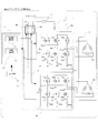
- Embodiment 1 of this invention It is a block diagram of the electric power steering control apparatus in Embodiment 1 of this invention.
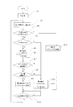
- 3 is a flowchart showing an electric power steering control method according to Embodiment 1 of the present invention.
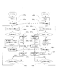
- 7 is a flowchart showing an electric power steering control method according to Embodiment 2 of the present invention.
- 10 is a flowchart showing an electric power steering control method according to Embodiment 3 of the present invention.
- FIG. FIG. 1 is a configuration diagram of an electric power steering control apparatus according to Embodiment 1 of the present invention. First, the configuration of the electric power steering control device according to the first embodiment and the function of each component will be described with reference to FIG.
- the electric power steering control device shown in FIG. 1 includes an ECU 1 (control unit) that controls the electric power steering control device, a sensor group 2 including a torque sensor and a vehicle speed sensor that detect torque of the electric power steering device, and the like.
- the electric power steering apparatus is configured to include two sets of three-phase motors 3 and circuit blocks (reference numerals 5 to 9 in the drawing) of the electric power steering control apparatus.
- the circuit block includes a choke coil 5, a relay 6, an input information signal group 7, a control signal group 8, and an inverter circuit 9.
- this circuit block is often built in the ECU 1, but in FIG. 1, the circuit block is shown separately from the ECU 1 for easy understanding.
- the motor 3 is not limited to two sets and three phases, but may be n sets and m phases (n and m are natural numbers of 2 or more). Assume three phases. Further, in FIG. 1, since the two sets of relays 6a and 6b and the two sets of inverter circuits 9a and 9b have the same configuration, a and b are added to the reference numerals.
- the choke coil 5 suppresses circuit block noise from going out of the electric power steering control device.
- the relay 6a and the relay 6b are arranged independently, and open and close a connection between an inverter circuit 9a and an inverter circuit 9b, which will be described later, and the battery 4 of the vehicle, respectively, by a control signal group 8 output from the ECU 1.
- the inverter circuit 9 includes an inverter circuit 9a and an inverter circuit 9b each having a plurality of switching elements so that the multiphase windings 3a and 3b of the motor 3 can be independently driven.
- the CPU 1 is built in the ECU 1, and the control signal group 8 to the relay 6 and the inverter circuit 9 and the input information signal group 7 from the inverter circuit 9 are connected.
- the CPU 10 calculates the control signal group 8 based on the information from the sensor group 2 and the input information signal group 7 from the inverter circuit 9, and outputs a control amount calculation unit 11, a plurality of multiphase windings 3a, 3b and a failure detection unit 12 for performing an initial check process of a motor drive unit including a plurality of inverter circuits 9a and 9b.
- the ECU 1 includes an interface circuit network, but is not shown.
- the inverter circuits 9a and 9b correspond to the multi-phase windings 3a and 3b, the upper and lower arm switching elements (T1 to T6), the shunt resistors (Ru, Rv, and Rw) for detecting the phase current, and noise prevention.
- the capacitor C1 is built in. Further, in order to obtain information on the inverter circuits 9a and 9b being driven, the terminal voltages (Mu, Mv, Mw) of the motor 3 and the resistance voltages (Iu, Iv, Iw) for current detection are respectively It is transmitted to the CPU 10 via the input information signal group 7.
- FIG. 2 is a flowchart showing the electric power steering control method according to Embodiment 1 of the present invention.
- step S1 When the CPU 10 is powered on, in step S1, the CPU 10 initializes each port, RAM, and the like. Next, in step S ⁇ b> 2, the CPU 10 inputs various input information from the sensor group 2.
- the various types of input information include, for example, information on torque sensors, vehicle speed sensors, and terminal voltages of the inverter circuit 9 that detect the steering operation force of the driver.
- step S3 the CPU 10 checks whether or not the initial check performed when the power is turned on has been executed. This initial check is performed every time power is supplied to the CPU 10 to check whether there is a failure in the motor drive unit including the plurality of multiphase windings 3a, 3b and the plurality of inverter circuits 9a, 9b of the electric power steering control device. It is something to check.
- the initial check process corresponds to a part of the function of the failure detection unit 12 shown in FIG.
- the CPU 10 includes a motor including the multiphase winding 3a and the inverter circuit 9a which are the first set of the plurality of multiphase windings 3a and 3b and the plurality of inverter circuits 9a and 9b.
- An initial check of a drive unit (hereinafter simply referred to as “first set”) and a motor drive unit (hereinafter simply referred to as “second set”) including a second set of multiphase windings 3b and an inverter circuit 9b is performed. Check only whether it has been executed. If the initial check has been completed, the answer is Y (Yes), and if not, the answer is N (No).
- step S3 checks whether the two sets have been checked.
- the CPU 10 checks whether or not the first set has been checked in step S4. If the first set has not been checked (N), the CPU 10 performs an initial check on the first set of multiphase windings 3a and the inverter circuit 9a in step S5.
- step S5 the CPU 10 can detect the voltage of the battery 4 with the relay 6a in FIG. 1 opened, or can the voltage be detected in the same manner with the relay 6a closed, Sequentially checks whether a voltage is generated by driving the switching element. If no failure is detected in this diagnosis process, the CPU 10 sets the flag “1stIF” to (“H”: High) in step S6. The setting of this flag “1stIF” means that the first set of initial checks has been completed.
- the CPU 6 closes the relay 6a and establishes power supply so that the inverter circuit 9a can be driven at any time.
- the CPU 10 sets the “1stIF” flag, although the contents of the control processing to be performed later differ according to the detected contents.
- the CPU 10 may leave the relay 6a opened depending on the failure state. In such a case, it becomes a mode in which power cannot be supplied to the first set of multiphase windings 3a.
- the CPU 10 closes the relay 6a and can supply power in the case of a partial failure of the switching element, but does not drive the system in which the failure occurs, for example, T1a or T2a, so-called two-phase driving. Sometimes. In such a case, the presence or absence of each failure is clarified using each failure factor flag (not shown) for these check results.
- step S7 the CPU 10 checks whether the control of the motor 3 is immediately started based on various input information from the sensor group 2. If control of the motor 3 is necessary (Y), the process proceeds to step S8. For example, the case where the driver is operating the steering wheel, that is, when the torque sensor detects a torque greater than a predetermined value corresponds to such a case.
- step S8 the CPU 10 checks whether or not there is a failure in the first set subjected to the initial check. If there is no failure, that is, if it is normal, the process proceeds to step S9, and the power steering control of the motor 3 is executed only by the first set. This control is the same as the normal control process described later, but starts driving the motor 3 for only the first set. Further, since control of the motor 3 is started for the first time, and the data of the inverter circuit 9a is not so important, the control signal group 8 may be output by the simplest possible calculation. That is, in this step S8, the CPU 10 executes arithmetic processing of only the minimum simplified control signal group 8 determined in advance on the inverter circuit 9a that has completed the initial check normally. The drive control of the phase winding 3a can be executed earlier.
- step S8 determines whether a failure has occurred in the first group (N)
- the motor 3 does not require control (step S7: N), or the first group has been initially checked (step S4: Y)
- step S10 the CPU 10 Advances to step S10, and this time, the second set of multiphase windings 3b and the inverter circuit 9b are checked. The contents of the check are the same as in the first set. If no failure is detected in the diagnostic process by the initial check, the second set of initial checked flags “2ndIF” is set and the relay 6b is closed. If a failure is detected, a signal is output to the relay 6b according to the detected content, and an initial check completed flag “2ndIF” is set.
- step S3 when both the “1stIF” and “2ndIF” initial-checked flags are set, that is, the initial checks of both the multi-phase windings 3a and 3b and the inverter circuits 9a and 9b are completed. If yes (Y), the CPU 10 proceeds to step S13.
- step S13 the CPU 10 executes control processing for a normal electric power steering device. Specifically, the CPU 10 calculates a target control amount based on various input information from the sensor group 2. Then, the CPU 10 calculates a final control amount by feedback control corresponding to the difference from the target value from the current detection of the motor 3. Further, the CPU 10 outputs a control signal group 8 to the respective inverter circuits 9a and 9b in accordance with the phase difference between the two sets of multiphase windings 3a and 3b.
- step S13 includes a periodic failure determination check similar to or different from the initial check.
- the CPU 10 executes a sensor failure, a voltage check for each circuit, and the like.
- the initial check is divided into the first set of inverter circuits 9a and multiphase windings 3a, the second set of inverter circuits 9b and multiphase windings 3b, and the first set is given priority.
- a diagnostic process was executed. For other, for example, ROM, RAM, battery 4 voltage, sensor group 2 relationship, etc. inside the CPU 10, priorities are determined in advance, and higher priority is included in the first set of checks, and vice versa.
- the low priority items are divided by sending them to the second set of checks. It is also conceivable to insert a failure determination of a related part necessary for starting control of the first group into the first group and insert the other into the second group. By executing such division processing, it is possible to start the first set of controls as early as possible.
- electric power steering control including a motor 3 having a plurality of multiphase windings 3a and 3b and a plurality of inverter circuits 9a and 9b corresponding to the plurality of multiphase windings.
- the set of the multiphase windings 3a, 3b and the inverter is given priority, the initial check is preferentially executed from the set with the highest priority, and control of the set is immediately started when each is finished. You can complete the preparation as you can.
- control start is necessary, control is started only for the group that has been prepared. It can also be configured as follows. As a result, it is possible to start the control earlier than in the conventional device in which a plurality of sets are collectively checked, and quick power steering control in accordance with the driver's intention is possible.
- step S5 and S10 The technical features by the processing of the CPU 10 in the first embodiment shown in FIG. 2 are summarized as follows.
- An initial check is individually executed for each set of the multiphase windings 3a and 3b and the inverter circuits 9a and 9b (steps S5 and S10).
- step S5 and S10 The opening / closing control of the plurality of relays 6a, 6b is executed so as to distribute the power supply timing to the plurality of inverter circuits 9a, 9b according to the result of the initial check.
- the opening / closing control is executed for the corresponding relays 6a and 6b in order from the group in which the initial check is completed (steps S5, S6, steps S10, S11).
- step S9 The drive control of the plurality of inverter circuits 9a and 9b is performed so as to disperse the currents flowing through the plurality of multiphase windings 3a and 3b according to the result of the initial check.
- the initial check is performed according to the result of the initial check.
- Step S8 drive control of the inverter circuits 9a and 9b of the set for which the initial check has been completed is executed (Step S9).
- the steering assist torque is generated using the electric power steering control device having a configuration including a plurality of sets of the multiphase winding and the inverter circuit, and the driver is steered.
- failure detection of each group by the initial check is performed in order based on the priority assigned to each group.
- preparation for starting control can be completed as a power supply state, and actual control can be started as necessary.
- power supply to a plurality of multiphase windings is not performed at the same time, and failure determination and control start timing can be efficiently performed for each group according to priority order, thereby speeding up motor control start. It becomes possible.
- Embodiment 2 in the electric power steering control device having a configuration including a plurality of sets of the multiphase windings 3a and 3b and the inverter circuits 9a and 9b, the electric check is performed before the initial check of all the sets is completed.
- the method of driving with the control content corresponding to the diagnosis result in order from the group in which the initial check is completed has been described.
- a method of driving at least one of the motor drive units determined to have no failure after the diagnosis process of all the motor drive units will be described.
- FIG. 3 is a flowchart showing an electric power steering control method according to Embodiment 2 of the present invention.
- the initial check process by the CPU 10 of the electric power steering control device according to the second embodiment will be described with reference to FIG.
- FIG. 3 the same processes as those in FIG. 2 of the first embodiment are denoted by the same reference numerals, and description of the steps with the same reference numerals is omitted.
- step S3A the CPU 10 checks whether or not the initial check has been completed. This check can be performed with a flag “Flag” described later. In the second embodiment, a single completion flag is used as a whole instead of having individual completion flags for each set of the multiphase windings 3a and 3b and the inverter circuits 9a and 9b.
- the CPU 10 proceeds to step S5A and performs the first set of initial checks. The contents of the first set of initial checks are the same as those in the first embodiment.
- step S5A the CPU 10 controls the relay 6a according to the result of the first set of initial checks. Specifically, when there is no failure, the relay 6a is closed, and when the failure is large enough to cause a failure, the relay 6a is opened.
- step S10A the CPU 10 performs a second set of initial checks in the same manner as in the previous step S5A.
- the initial check flag “Flag” is set (High), and the check result is set.
- the relay 6b is controlled accordingly.
- the failure diagnosis process of the electric power steering apparatus continuously processes the initial checks of the two sets of motor drive units.
- the CPU 10 checks in step S8A whether or not there is no failure in the first set.
- the CPU 10 checks in step S14 whether or not there is a failure in the second group.
- control is not possible and the process is terminated, and the process proceeds to step S12.
- step S9 the CPU 10 calculates and outputs the control signal group 8 so as to drive the first set of multiphase windings 3a. If it is determined in step S14 that there is no failure (step S14: Y), in step S15, the CPU 10 calculates and outputs the control signal group 8 so as to drive the second set of multiphase windings 3b. .
- control amount calculation / output of the control signal group 8 by the CPU 10 in step S9 or step S15 may be different from the normal control amount calculation in step S13. Since the control is started for the first time this time, for example, the current, voltage, and the like of the motor 3 do not require information because the motor 3 is not driven. Furthermore, in the next predetermined cycle, normal control amount calculation / output is performed in step S13, so that the calculations in steps S9 and S15 can be simplified compared to step S13, and as a result The time required can be completed in a short time.
- step S9 and step S15 the calculation process takes a short time compared to the case of performing two sets of calculations in step S9 and step S15. Therefore, when it is necessary to immediately start the control of the electric power steering device, the control can be started earlier only with one set.
- step S5A An initial check is individually executed for each set of the multiphase windings 3a, 3b and the inverter circuits 9a, 9b (step S5A, step S10A).
- step S5A An initial check is individually executed for each set of the multiphase windings 3a, 3b and the inverter circuits 9a, 9b (step S5A, step S10A).
- step S5A The opening / closing control of the plurality of relays 6a, 6b is executed so as to distribute the power supply timing to the plurality of inverter circuits 9a, 9b according to the result of the initial check.
- the opening / closing control is executed for the corresponding relays 6a and 6b in order from the group in which the initial check is completed within one processing cycle (steps S5A, S10A, and S11A).
- step S9, step S15 The drive control of the plurality of inverter circuits 9a and 9b is performed so as to disperse the current flowing through the plurality of multiphase windings 3a and 3b according to the result of the initial check.
- step S9, step S15 the initial check is performed according to the result of the initial check.
- step S8A, step S14 drive control of the inverter circuits 9a and 9b of the set in which the initial check is completed is executed (steps S9 and S15).
- the initial check of the electric power steering control device having a configuration including a plurality of sets of multiphase windings and inverter circuits is performed based on the priority order assigned to each set. Is processed. Then, according to the initial check result, the relays can be independently controlled to be in a power supply state, and preparation for starting control can be completed.
- the control is started first only for that group.
- the power supply to the motor is not performed simultaneously, the start of power steering control can be efficiently performed for each group according to the priority order, and the start of motor control can be accelerated. That is, according to the second embodiment, as in the first embodiment, the electric power steering apparatus can be controlled at an earlier stage according to the driver's intention. it can.
- step S7 the initial check of the first group and the second group has already been completed before determining whether or not the power steering control is necessary in step S7. Therefore, the following processing is also possible by merging the processing of step S8A and step S8B. That is, since a part of the switching element in the first set is broken, it is necessary to perform two-phase driving. On the other hand, when all of the second set is normal and normal three-phase driving is possible, Instead of starting two-phase driving with only one set, it is possible to start three-phase driving with only the second set.
- Embodiment 3 FIG. In previous Embodiment 1 and 2, the example in case ECU1 has one CPU10 was shown. On the other hand, in the third embodiment, as an example in the case where the ECU 1 has a plurality of CPUs 10, the CPU 1 has two CPUs 10a and 10b, and each of the CPUs 10 independently performs an initial check of the electric power steering control device. How to do will be described.
- FIG. 4 is a flowchart showing an electric power steering control method according to Embodiment 3 of the present invention. Next, an initial check process by the CPU 10 of the electric power steering control device according to the third embodiment will be described with reference to FIG.
- one CPU 10 controls the two inverter circuits 9a and 9b.
- the third embodiment has two CPUs 10a and 10b, which are configured such that the CPU 10a controls the inverter circuit 9a and the CPU 10b controls the inverter circuit 9b.
- a symbol a is added to the processing step of the CPU 10a
- a symbol b is added to the processing step of the CPU 10b.
- CPU10a and CPU10b are equivalent CPU10, and the process step is also substantially the same. Therefore, in the following description, processing steps of the CPU 10a will be mainly described. Note that the CPU 10 is not limited to two, and may be any natural number greater than or equal to two. However, in the following description, two CPUs 10 are assumed for simplicity.
- step S20a When the CPU 10a is powered on, first, in step S20a, the CPU 10a initializes ports, RAM, and the like. Next, before the processing routine of the fixed cycle Tx is started, in step S21a, the CPU 10a performs communication with the CPU 10b (hereinafter referred to as “first communication”). In the first communication stage, control has not yet started, and the CPU 10a has not obtained input information or the like. Therefore, the primary purpose of the first communication is to synchronize the CPU 10a and the CPU 10b.
- communication data it is possible to include information such as the time that it owns, past data, past failures, etc., and it is possible to transmit and receive such communication data between the CPUs 10a and 10b. Is possible. Further, by receiving the information of the other party, each of the CPUs 10a and 10b can perform time alignment and synchronize with each other.
- step S22a the CPU 10a inputs various input information from the sensor group 2 as in step S2 of FIG.
- step S23a the CPU 10a checks whether or not the first set of initial checks has been executed. Similar to step S4 in FIG. 2, this check can be easily checked by a flag “1stIF” described later.
- step S24a the CPU 10a performs an initial check on the first set of multiphase windings 3a, the inverter circuit 9a, and the like.
- step S24b the CPU 10a performs an initial check on the second set of multiphase windings 3b, the inverter circuit 9b, and the like in step S24a.
- the contents of the initial check regarding the first group and the second group are the same as those in the first embodiment.
- the sensors, the voltage of the battery 4 and the like that are not related to the first set and the second set can be shared by the CPU 10a and the CPU 10b, and can be checked by one CPU 10.
- both the CPU 10a and the CPU 10b can independently perform checks and collate the results with each other.
- the CPU 10a After completing the first set of initial checks, the CPU 10a sets an end flag “1stIF” (High) in step S25a. Further, the CPU 10a closes the relay 6a if no failure is detected in the first set. If a failure is detected in the first set, the CPU 10a controls the relay 6a according to the failure content and stores the failure content. On the other hand, in step S25b, the CPU 10b similarly sets the flag “2ndIF” (High). Further, the CPU 10b stores the details of the failure detection, but the relay 6b is not controlled in step S24b.
- step S26a the CPU 10a performs communication with the CPU 10b again (hereinafter referred to as “second communication”).
- second communication in addition to the synchronization of both the CPUs 10, it is possible to transmit the contents of the failure at the initial check and to collate the input information by data transmission / reception.
- both CPU10 can grasp
- the output of the other normal inverter circuit 9 may be increased. Is possible. Further, since the synchronization is performed at least once every fixed period Tx, it is possible to reliably hold the phase shift between the two sets of control.
- CPU10b controls the relay 6b according to the result of failure detection in step S31 instead of previous step S24b.
- the CPU 10a and the CPU 10b can disperse the timing at which the consumption current is generated by shifting the closing timing of the relay 6a and the relay 6b.
- step S30a the CPU 10a can repeatedly execute step S22a and subsequent steps at a constant cycle Tx by checking whether or not the fixed cycle Tx has elapsed.
- step S27a the CPU 10a checks in step S27a whether or not the control of the motor 3 is immediately started based on various input information from the sensor group 2.
- the control amount of the control signal group 8 is calculated.
- the CPU 10a calculates the difference between the target control amount and the current of the current motor 3 and performs the feedback control to calculate the output control amount.
- step S28a the CPU 10a performs communication with the CPU 10b again (hereinafter referred to as “third communication”).
- third communication as described above, synchronization can be performed, and further data such as control amount and input information can be transmitted and received, and both CPUs 10 can also check the other party's failure.
- step S29a the CPU 10a performs output processing of the control signal group 8 and supplies current to the motor 3.
- the CPU 10a controls the switching element of the inverter circuit 9a
- the CPU 10b controls the switching element of the inverter circuit 9b.
- the CPUs 10a and 10b equally divide the output control amount into two, the output amount is the same on average, but is shifted in time.
- each of the CPUs 10a and 10b can control the output amount itself so that one output is larger than the other according to the failure state.
- An initial check is individually executed by a plurality of independent CPUs 10a and 10b for each set of the multiphase windings 3a and 3b and the inverter circuits 9a and 9b (steps S24a and S24b).
- the opening / closing control of the plurality of relays 6a, 6b is executed so as to distribute the power supply timing to the plurality of inverter circuits 9a, 9b according to the result of the initial check.
- different CPUs 10a, 10b perform mutual communication (steps S21a, 21b, steps S26a, S26b), and open / close control is performed so that the corresponding relays 6a, 6b do not overlap with each other. (Step S24a, Step S31). (3) The drive control of the plurality of inverter circuits 9a and 9b is performed so as to disperse the currents flowing through the plurality of multiphase windings 3a and 3b according to the result of the initial check (steps S29a and S29b). .
- step S28a and S28b when different CPUs 10a and 10b perform mutual communication (steps S28a and S28b) and a power steering control request is received as input information (steps S27a and 27b), an initial check is performed.
- Each of the CPUs 10a and 10b executes drive control of the inverter circuits 9a and 9b in accordance with the result of implementation (steps S29a and S29b).
- control of a plurality of multiphase windings is started by performing mutual communication and sharing each other's information.
- the power supply timing can be easily shifted.
Landscapes
- Engineering & Computer Science (AREA)
- Chemical & Material Sciences (AREA)
- Combustion & Propulsion (AREA)
- Transportation (AREA)
- Mechanical Engineering (AREA)
- Power Steering Mechanism (AREA)
- Control Of Ac Motors In General (AREA)
- Steering Control In Accordance With Driving Conditions (AREA)
Abstract
Description
特許文献1の電動パワーステアリング制御装置は、全ての故障診断処理の終了を待って、モータの各多相巻線への電流供給を同時に開始するようにしている。ここで、通常は、電動パワーステアリング制御装置へ電源が投入されると、まず、制御装置に搭載されたCPUが、故障判定処理を行う。しかしながら、エンジン始動直後のような場合には、モータの各多相巻線に電流が同時に供給されると、エンジンにも急激に電流が流れて、エンジン回転へ不調をきたす可能性があった。
(1)複数組に関するイニシャルチェックを、組ごとに個別に実行する。
(2)イニシャルチェックの実施結果に応じて、複数のインバータ回路への電源供給タイミングを分散化するように、複数のリレーの開閉制御を実行する。
(3)イニシャルチェックの実施結果に応じて、複数の多相巻線に流れる電流を分散化するように、複数のインバータ回路の駆動制御を行う。
この結果、各多相巻線に電流が同時に供給されることを抑制した上で、早期に電動パワーステアリング制御を開始することのできる電動パワーステアリング制御装置および電動パワーステアリング制御方法を得ることができる。
図1は、本発明の実施の形態1における電動パワーステアリング制御装置の構成図である。まず、図1を用いて、本実施の形態1の電動パワーステアリング制御装置の構成と各構成要素の機能について説明する。
(1)多相巻線3a、3bとインバータ回路9a、9bの組ごとに、イニシャルチェックを個別に実行する(ステップS5、ステップS10)。
(2)イニシャルチェックの実施結果に応じて、複数のインバータ回路9a、9bへの電源供給タイミングを分散化するように、複数のリレー6a、6bの開閉制御を実行する。特に、本実施の形態1では、イニシャルチェックが完了した組から順に、対応するリレー6a、6bに関して開閉制御を実行する(ステップS5、S6、ステップS10、S11)。
(3)イニシャルチェックの実施結果に応じて、複数の多相巻線3a、3bに流れる電流を分散化するように、複数のインバータ回路9a、9bの駆動制御を行う(ステップS9)。特に、本実施の形態1では、複数組の全てに対するイニシャルチェックが完了していない時点で、入力情報としてパワーステアリング制御要求を受信した場合(ステップS7)には、イニシャルチェックの実施結果に応じて(ステップS8)、イニシャルチェックが完了している組のインバータ回路9a、9bの駆動制御を実行する(ステップS9)。
先の実施の形態1では、多相巻線3a、3bとインバータ回路9a、9bの組を複数有する構成を備えた電動パワーステアリング制御装置において、全ての組のイニシャルチェックが完了する前に、電動パワーステアリング制御が必要な場合には、イニシャルチェックが完了した組から順に、診断結果に応じた制御内容で駆動させる方法について説明した。これに対して、本実施の形態2では、全てのモータ駆動部の診断処理後に、故障なしと判断されたモータ駆動部のうち少なくとも1つを駆動させる方法について説明する。
(1)多相巻線3a、3bとインバータ回路9a、9bの組ごとに、イニシャルチェックを個別に実行する(ステップS5A、ステップS10A)。
(2)イニシャルチェックの実施結果に応じて、複数のインバータ回路9a、9bへの電源供給タイミングを分散化するように、複数のリレー6a、6bの開閉制御を実行する。特に、本実施の形態2では、1回の処理周期内で、イニシャルチェックが完了した組から順に、対応するリレー6a、6bに関して開閉制御を実行する(ステップS5A、ステップS10A、S11A)。
(3)イニシャルチェックの実施結果に応じて、複数の多相巻線3a、3bに流れる電流を分散化するように、複数のインバータ回路9a、9bの駆動制御を行う(ステップS9、ステップS15)。特に、本実施の形態2では、複数組の全てに対するイニシャルチェックが完了した時点で、入力情報としてパワーステアリング制御要求を受信した場合(ステップS7)には、イニシャルチェックの実施結果に応じて(ステップS8A、ステップS14)、イニシャルチェックが完了している組のインバータ回路9a、9bの駆動制御を実行する(ステップS9、S15)。
先の実施の形態1および2では、ECU1が、1つのCPU10を有する場合の例を示した。これに対して、本実施の形態3では、ECU1が複数のCPU10を有する場合の1例として、2つのCPU10a、10bを有し、それぞれのCPU10が独立に電動パワーステアリング制御装置のイニシャルチェックを実施する方法について説明する。
(1)多相巻線3a、3bとインバータ回路9a、9bの組ごとに、独立した複数のCPU10a、10bによりイニシャルチェックを個別に実行する(ステップS24a、ステップS24b)。
(2)イニシャルチェックの実施結果に応じて、複数のインバータ回路9a、9bへの電源供給タイミングを分散化するように、複数のリレー6a、6bの開閉制御を実行する。特に、本実施の形態3では、異なるCPU10a、10bが相互通信を行いながら(ステップS21a、21b、ステップS26a、S26b)、対応するリレー6a、6bに関して相互のタイミングが重複しないように開閉制御を実行する(ステップS24a、ステップS31)。
(3)イニシャルチェックの実施結果に応じて、複数の多相巻線3a、3bに流れる電流を分散化するように、複数のインバータ回路9a、9bの駆動制御を行う(ステップS29a、ステップS29b)。特に、本実施の形態3では、異なるCPU10a、10bが相互通信を行いながら(ステップS28a、ステップS28b)、入力情報としてパワーステアリング制御要求を受信した場合(ステップS27a、ステップ27b)には、イニシャルチェックの実施結果に応じて、それぞれのCPU10a、10bがインバータ回路9a、9bの駆動制御を実行する(ステップS29a、S29b)。
Claims (8)
- 複数の多相巻線を有するモータと、
前記複数の多相巻線のそれぞれを個別に駆動制御する複数のインバータ回路と、
一端が電源と接続され、閉成することで前記複数のインバータ回路のそれぞれを個別に電源供給状態とする複数のリレーと、
電源投入時には、前記複数の多相巻線と、前記複数の多相巻線にそれぞれ対応する前記複数のインバータ回路とで構成される複数組について故障の有無を判断するためのイニシャルチェックを実施するとともに、前記イニシャルチェックの実施後には、前記イニシャルチェックの実施結果に基づいて、前記複数のリレーの開閉制御およびセンサ群からの入力情報を基にして、前記複数のインバータ回路の駆動制御を実行することで、パワーステアリング制御を実行する制御部と
を備えた電動パワーステアリング制御装置であって、
前記制御部は、
前記複数組に関する前記イニシャルチェックを組ごとに個別に実行し、
前記イニシャルチェックの実施結果に応じて、前記複数のインバータ回路への電源供給タイミングを分散化するように、前記複数のリレーの前記開閉制御を実行し、
前記イニシャルチェックの実施結果に応じて、前記複数の多相巻線に流れる電流を分散化するように、前記複数のインバータ回路の駆動制御を実行する
電動パワーステアリング制御装置。 - 請求項1に記載の電動パワーステアリング制御装置において、
前記制御部は、
前記複数組に関する前記イニシャルチェックをあらかじめ決められた優先順位に従って順番に実行するとともに、前記イニシャルチェックが完了した組から順に、対応するリレーに関して前記開閉制御を実行することを、一定周期で順次実行し、
前記複数組の全てに対するイニシャルチェックが完了していない時点で、前記入力情報としてパワーステアリング制御要求を受信した場合には、前記イニシャルチェックの実施結果に応じて、前記複数の多相巻線のうちイニシャルチェックが完了している組の多相巻線に流れる電流を分散化するように、前記イニシャルチェックが完了している組のインバータ回路の駆動制御を実行する
電動パワーステアリング制御装置。 - 請求項1に記載の電動パワーステアリング制御装置において、
前記制御部は、
前記複数組に関する前記イニシャルチェックをあらかじめ決められた優先順位に従って順番に実行するとともに、前記イニシャルチェックが完了した組から順に、対応するリレーに関して前記開閉制御を実行することを、1回の周期内で順次実行し、
前記複数組の全てに対するイニシャルチェックが完了した後、前記入力情報としてパワーステアリング制御要求を受信した場合には、前記イニシャルチェック結果に応じて、前記複数の多相巻線に流れる電流を分散化するように、前記複数のインバータ回路の駆動制御を実行する
電動パワーステアリング制御装置。 - 請求項1に記載の電動パワーステアリング制御装置において、
前記制御部は、前記複数組のそれぞれの組に対応して、前記イニシャルチェック、前記開閉制御、および前記駆動制御を一定周期で個別に実行する複数の個別制御部を有し、
前記複数の個別制御部のそれぞれは、
他の個別制御部と相互通信を実行することで、他の個別制御部との間で、それぞれのイニシャルチェックの実施結果、開閉制御状態、および駆動制御状態に関する情報を共有化する通信処理部を有し、
自身の組のイニシャルチェックの実施結果および他の個別制御部のイニシャルチェックの実施結果に応じて、前記複数のインバータ回路への電源供給タイミングを分散化するように、自身の組のリレーの前記開閉制御を実行し、
自身の組のイニシャルチェックの実施結果および他の個別制御部のイニシャルチェックの実施結果に応じて、前記複数の多相巻線に流れる電流を分散化するように、自身の組のインバータ回路の駆動制御を実行する
電動パワーステアリング制御装置。 - 請求項2または3に記載の電動パワーステアリング制御装置において、
前記制御部は、
前記イニシャルチェックが完了したことを検知した周期と同一周期内で、前記入力情報としてパワーステアリング制御要求を受信した場合には、あらかじめ決められた最低限の簡略化された制御演算処理により前記駆動制御を実行する
電動パワーステアリング制御装置。 - 請求項4に記載の電動パワーステアリング制御装置において、
前記複数の個別制御部のそれぞれは、
前記通信処理部による前記他の個別制御部との前記相互通信を、前記一定周期内で少なくとも1回実行し、
前記複数の個別制御部が2個の個別制御部で構成される場合には、一方の個別制御部は、前記相互通信の実行前に自身の組のリレーの前記開閉制御を実行し、他方の個別制御部は、前記相互通信の実行後に自身の組のリレーの前記開閉制御を実行する
電動パワーステアリング制御装置。 - 請求項4に記載の電動パワーステアリング制御装置において、
前記複数の個別制御部のそれぞれは、前記複数組のいずれの組であるかを識別するために設定されるフラグに応じて、前記電源供給タイミングを分散化するための処理、および前記複数の多相巻線に流れる電流を分散化するための処理のタイミングを切り換えるようにした同一のプログラムを用いる
電動パワーステアリング制御装置。 - 複数の多相巻線を有するモータと、
前記複数の多相巻線のそれぞれを個別に駆動制御する複数のインバータ回路と、
一端が電源と接続され、閉成することで前記複数のインバータ回路のそれぞれを個別に電源供給状態とする複数のリレーと、
電源投入時には、前記複数の多相巻線と、前記複数の多相巻線にそれぞれ対応する前記複数のインバータ回路とで構成される複数組についてイニシャルチェックを実施するとともに、前記イニシャルチェックの実施後には、前記イニシャルチェックの実施結果に基づいて、前記複数のリレーの開閉制御およびセンサ群からの入力情報を基にして、前記複数のインバータ回路の駆動制御を実行することで、パワーステアリング制御を実行する制御部と
を備えた電動パワーステアリング制御装置において、前記制御部によって実行される電動パワーステアリング制御方法であって、
前記複数組に関する前記イニシャルチェックを組ごとに個別に実行する個別イニシャルチェック実行ステップと、
前記イニシャルチェックの実行結果に応じて、前記複数のインバータ回路への電源供給タイミングを分散化するように、前記複数のリレーの前記開閉制御を実行する開閉制御ステップと、
前記イニシャルチェックの実施結果に応じて、前記複数の多相巻線に流れる電流を分散化するように、前記複数のインバータ回路の駆動制御を実行する駆動制御ステップと
を有する電動パワーステアリング制御方法。
Priority Applications (5)
| Application Number | Priority Date | Filing Date | Title |
|---|---|---|---|
| JP2015546225A JP6109332B2 (ja) | 2013-11-08 | 2013-11-08 | 電動パワーステアリング制御装置および電動パワーステアリング制御方法 |
| US15/022,047 US9862406B2 (en) | 2013-11-08 | 2013-11-08 | Electric power steering control apparatus and electric power steering control method |
| PCT/JP2013/080237 WO2015068260A1 (ja) | 2013-11-08 | 2013-11-08 | 電動パワーステアリング制御装置および電動パワーステアリング制御方法 |
| CN201380080730.0A CN105705401B (zh) | 2013-11-08 | 2013-11-08 | 电动助力转向控制装置及电动助力转向控制方法 |
| EP13897075.1A EP3067251B1 (en) | 2013-11-08 | 2013-11-08 | Electric power steering control device and electric power steering control method |
Applications Claiming Priority (1)
| Application Number | Priority Date | Filing Date | Title |
|---|---|---|---|
| PCT/JP2013/080237 WO2015068260A1 (ja) | 2013-11-08 | 2013-11-08 | 電動パワーステアリング制御装置および電動パワーステアリング制御方法 |
Publications (1)
| Publication Number | Publication Date |
|---|---|
| WO2015068260A1 true WO2015068260A1 (ja) | 2015-05-14 |
Family
ID=53041062
Family Applications (1)
| Application Number | Title | Priority Date | Filing Date |
|---|---|---|---|
| PCT/JP2013/080237 Ceased WO2015068260A1 (ja) | 2013-11-08 | 2013-11-08 | 電動パワーステアリング制御装置および電動パワーステアリング制御方法 |
Country Status (5)
| Country | Link |
|---|---|
| US (1) | US9862406B2 (ja) |
| EP (1) | EP3067251B1 (ja) |
| JP (1) | JP6109332B2 (ja) |
| CN (1) | CN105705401B (ja) |
| WO (1) | WO2015068260A1 (ja) |
Cited By (5)
| Publication number | Priority date | Publication date | Assignee | Title |
|---|---|---|---|---|
| WO2017122329A1 (ja) * | 2016-01-14 | 2017-07-20 | 三菱電機株式会社 | 電動パワーステアリング装置 |
| JP2017169386A (ja) * | 2016-03-17 | 2017-09-21 | 株式会社デンソー | 制御システム |
| CN108367774A (zh) * | 2015-12-28 | 2018-08-03 | 三菱电机株式会社 | 线控转向方式的电动助力转向装置及其控制方法 |
| WO2018147402A1 (ja) * | 2017-02-10 | 2018-08-16 | 株式会社デンソー | 回転電機制御装置、および、これを用いた電動パワーステアリング装置 |
| JP2020039201A (ja) * | 2018-09-03 | 2020-03-12 | 株式会社ジェイテクト | 車両制御装置 |
Families Citing this family (7)
| Publication number | Priority date | Publication date | Assignee | Title |
|---|---|---|---|---|
| JP5999291B1 (ja) * | 2014-12-25 | 2016-09-28 | 日本精工株式会社 | 電動パワーステアリング装置 |
| JP6798476B2 (ja) * | 2017-11-30 | 2020-12-09 | 株式会社デンソー | モータ制御装置、モータ駆動システム、及び、モータ制御方法 |
| JP6992462B2 (ja) * | 2017-12-08 | 2022-01-13 | トヨタ自動車株式会社 | 外部給電システム及びその漏電検知方法 |
| JP2019158002A (ja) * | 2018-03-13 | 2019-09-19 | 株式会社デンソー | シフトレンジ制御装置 |
| JP7172306B2 (ja) | 2018-09-03 | 2022-11-16 | 株式会社ジェイテクト | 車両制御装置 |
| JP2021054304A (ja) * | 2019-09-30 | 2021-04-08 | 日本電産エレシス株式会社 | 電動パワーステアリング制御装置 |
| FR3119276B1 (fr) | 2021-01-27 | 2022-12-09 | Psa Automobiles Sa | Dispositif de supervision d’un systeme electrique comprenant une machine redondee |
Citations (4)
| Publication number | Priority date | Publication date | Assignee | Title |
|---|---|---|---|---|
| JP2004182039A (ja) * | 2002-12-02 | 2004-07-02 | Toyoda Mach Works Ltd | 車両の操舵制御装置 |
| JP2005032261A (ja) * | 2004-07-26 | 2005-02-03 | Honda Motor Co Ltd | 電子装置 |
| JP5146851B2 (ja) | 2010-01-07 | 2013-02-20 | 株式会社デンソー | 電動パワーステアリング装置 |
| JP2013079027A (ja) * | 2011-10-05 | 2013-05-02 | Denso Corp | 電動パワーステアリング装置 |
Family Cites Families (7)
| Publication number | Priority date | Publication date | Assignee | Title |
|---|---|---|---|---|
| CN201312278Y (zh) * | 2008-11-14 | 2009-09-16 | 郭少仪 | 中、高压大功率电机软起动器 |
| JP5158527B2 (ja) * | 2010-02-23 | 2013-03-06 | 株式会社デンソー | 電動機駆動装置、これを用いた電動パワーステアリング装置、及び、プログラム |
| JP5229644B2 (ja) * | 2010-06-24 | 2013-07-03 | 株式会社デンソー | 電動機駆動装置、および、これを用いた電動パワーステアリング装置 |
| CN202395542U (zh) * | 2011-11-28 | 2012-08-22 | 中国人民解放军徐州空军学院 | 一种多绕组双凸极发电机及输出变换与控制装置 |
| JP5995877B2 (ja) | 2012-01-11 | 2016-09-21 | 三菱電機株式会社 | 電動パワーステアリング装置 |
| JP5673605B2 (ja) * | 2012-05-30 | 2015-02-18 | 株式会社デンソー | 電動機駆動装置、および、これを用いた電動パワーステアリング装置 |
| CN203933305U (zh) * | 2014-04-01 | 2014-11-05 | 湖南德力科威科技有限公司 | 电动助力车用小型驱动电机 |
-
2013
- 2013-11-08 JP JP2015546225A patent/JP6109332B2/ja active Active
- 2013-11-08 US US15/022,047 patent/US9862406B2/en active Active
- 2013-11-08 CN CN201380080730.0A patent/CN105705401B/zh active Active
- 2013-11-08 EP EP13897075.1A patent/EP3067251B1/en active Active
- 2013-11-08 WO PCT/JP2013/080237 patent/WO2015068260A1/ja not_active Ceased
Patent Citations (4)
| Publication number | Priority date | Publication date | Assignee | Title |
|---|---|---|---|---|
| JP2004182039A (ja) * | 2002-12-02 | 2004-07-02 | Toyoda Mach Works Ltd | 車両の操舵制御装置 |
| JP2005032261A (ja) * | 2004-07-26 | 2005-02-03 | Honda Motor Co Ltd | 電子装置 |
| JP5146851B2 (ja) | 2010-01-07 | 2013-02-20 | 株式会社デンソー | 電動パワーステアリング装置 |
| JP2013079027A (ja) * | 2011-10-05 | 2013-05-02 | Denso Corp | 電動パワーステアリング装置 |
Non-Patent Citations (1)
| Title |
|---|
| See also references of EP3067251A4 |
Cited By (8)
| Publication number | Priority date | Publication date | Assignee | Title |
|---|---|---|---|---|
| CN108367774A (zh) * | 2015-12-28 | 2018-08-03 | 三菱电机株式会社 | 线控转向方式的电动助力转向装置及其控制方法 |
| WO2017122329A1 (ja) * | 2016-01-14 | 2017-07-20 | 三菱電機株式会社 | 電動パワーステアリング装置 |
| JPWO2017122329A1 (ja) * | 2016-01-14 | 2018-04-26 | 三菱電機株式会社 | 電動パワーステアリング装置 |
| JP2017169386A (ja) * | 2016-03-17 | 2017-09-21 | 株式会社デンソー | 制御システム |
| WO2018147402A1 (ja) * | 2017-02-10 | 2018-08-16 | 株式会社デンソー | 回転電機制御装置、および、これを用いた電動パワーステアリング装置 |
| JP2018129996A (ja) * | 2017-02-10 | 2018-08-16 | 株式会社デンソー | 回転電機制御装置 |
| JP2020039201A (ja) * | 2018-09-03 | 2020-03-12 | 株式会社ジェイテクト | 車両制御装置 |
| JP7155763B2 (ja) | 2018-09-03 | 2022-10-19 | 株式会社ジェイテクト | 車両制御装置 |
Also Published As
| Publication number | Publication date |
|---|---|
| US20160229444A1 (en) | 2016-08-11 |
| CN105705401B (zh) | 2018-05-29 |
| CN105705401A (zh) | 2016-06-22 |
| US9862406B2 (en) | 2018-01-09 |
| EP3067251A4 (en) | 2018-01-03 |
| JP6109332B2 (ja) | 2017-04-05 |
| EP3067251A1 (en) | 2016-09-14 |
| EP3067251B1 (en) | 2019-01-02 |
| JPWO2015068260A1 (ja) | 2017-03-09 |
Similar Documents
| Publication | Publication Date | Title |
|---|---|---|
| JP6109332B2 (ja) | 電動パワーステアリング制御装置および電動パワーステアリング制御方法 | |
| JP6505257B2 (ja) | 電動パワーステアリング装置 | |
| US10826423B2 (en) | Motor driving apparatus and motor driving method | |
| CN108698630B (zh) | 用于提高助力转向装置的失效安全性的计算和功能架构系统 | |
| CN107078681B (zh) | 电动机控制装置、电动助力转向装置及逆变器系统故障检测方法 | |
| US10486739B2 (en) | Motor actuator and power steering apparatus using the same | |
| JP6798476B2 (ja) | モータ制御装置、モータ駆動システム、及び、モータ制御方法 | |
| JP7052347B2 (ja) | モータ制御装置、モータ駆動システム、及び、モータ制御方法 | |
| US10666179B2 (en) | Control system | |
| EP3605834A1 (en) | Electric power steering device | |
| CN107921991B (zh) | 电动助力转向装置 | |
| JP2013113695A (ja) | 並列インバータ装置の誤配線検出装置 | |
| JP7225689B2 (ja) | モータ制御装置 | |
| CN115103793A (zh) | 转向辅助装置和方法以及转向系统 | |
| US20220250677A1 (en) | Motor drive system | |
| JP7435410B2 (ja) | モータ制御装置 | |
| JP2020039201A (ja) | 車両制御装置 | |
| JP5582748B2 (ja) | 車両用電子制御装置 | |
| JP2021054304A (ja) | 電動パワーステアリング制御装置 |
Legal Events
| Date | Code | Title | Description |
|---|---|---|---|
| 121 | Ep: the epo has been informed by wipo that ep was designated in this application |
Ref document number: 13897075 Country of ref document: EP Kind code of ref document: A1 |
|
| ENP | Entry into the national phase |
Ref document number: 2015546225 Country of ref document: JP Kind code of ref document: A |
|
| REEP | Request for entry into the european phase |
Ref document number: 2013897075 Country of ref document: EP |
|
| WWE | Wipo information: entry into national phase |
Ref document number: 2013897075 Country of ref document: EP |
|
| WWE | Wipo information: entry into national phase |
Ref document number: 15022047 Country of ref document: US |
|
| NENP | Non-entry into the national phase |
Ref country code: DE |