WO2015068584A1 - 自動変速機の制御装置 - Google Patents
自動変速機の制御装置 Download PDFInfo
- Publication number
- WO2015068584A1 WO2015068584A1 PCT/JP2014/078191 JP2014078191W WO2015068584A1 WO 2015068584 A1 WO2015068584 A1 WO 2015068584A1 JP 2014078191 W JP2014078191 W JP 2014078191W WO 2015068584 A1 WO2015068584 A1 WO 2015068584A1
- Authority
- WO
- WIPO (PCT)
- Prior art keywords
- rotational speed
- clutch
- engagement
- automatic transmission
- control device
- Prior art date
- Legal status (The legal status is an assumption and is not a legal conclusion. Google has not performed a legal analysis and makes no representation as to the accuracy of the status listed.)
- Ceased
Links
Images





Classifications
-
- F—MECHANICAL ENGINEERING; LIGHTING; HEATING; WEAPONS; BLASTING
- F16—ENGINEERING ELEMENTS AND UNITS; GENERAL MEASURES FOR PRODUCING AND MAINTAINING EFFECTIVE FUNCTIONING OF MACHINES OR INSTALLATIONS; THERMAL INSULATION IN GENERAL
- F16H—GEARING
- F16H61/00—Control functions within control units of change-speed- or reversing-gearings for conveying rotary motion ; Control of exclusively fluid gearing, friction gearing, gearings with endless flexible members or other particular types of gearing
- F16H61/04—Smoothing ratio shift
- F16H61/0403—Synchronisation before shifting
-
- F—MECHANICAL ENGINEERING; LIGHTING; HEATING; WEAPONS; BLASTING
- F16—ENGINEERING ELEMENTS AND UNITS; GENERAL MEASURES FOR PRODUCING AND MAINTAINING EFFECTIVE FUNCTIONING OF MACHINES OR INSTALLATIONS; THERMAL INSULATION IN GENERAL
- F16H—GEARING
- F16H3/00—Toothed gearings for conveying rotary motion with variable gear ratio or for reversing rotary motion
- F16H3/02—Toothed gearings for conveying rotary motion with variable gear ratio or for reversing rotary motion without gears having orbital motion
- F16H3/08—Toothed gearings for conveying rotary motion with variable gear ratio or for reversing rotary motion without gears having orbital motion exclusively or essentially with continuously meshing gears, that can be disengaged from their shafts
- F16H3/087—Toothed gearings for conveying rotary motion with variable gear ratio or for reversing rotary motion without gears having orbital motion exclusively or essentially with continuously meshing gears, that can be disengaged from their shafts characterised by the disposition of the gears
- F16H3/089—Toothed gearings for conveying rotary motion with variable gear ratio or for reversing rotary motion without gears having orbital motion exclusively or essentially with continuously meshing gears, that can be disengaged from their shafts characterised by the disposition of the gears all of the meshing gears being supported by a pair of parallel shafts, one being the input shaft and the other the output shaft, there being no countershaft involved
-
- F—MECHANICAL ENGINEERING; LIGHTING; HEATING; WEAPONS; BLASTING
- F16—ENGINEERING ELEMENTS AND UNITS; GENERAL MEASURES FOR PRODUCING AND MAINTAINING EFFECTIVE FUNCTIONING OF MACHINES OR INSTALLATIONS; THERMAL INSULATION IN GENERAL
- F16H—GEARING
- F16H61/00—Control functions within control units of change-speed- or reversing-gearings for conveying rotary motion ; Control of exclusively fluid gearing, friction gearing, gearings with endless flexible members or other particular types of gearing
- F16H61/04—Smoothing ratio shift
-
- F—MECHANICAL ENGINEERING; LIGHTING; HEATING; WEAPONS; BLASTING
- F16—ENGINEERING ELEMENTS AND UNITS; GENERAL MEASURES FOR PRODUCING AND MAINTAINING EFFECTIVE FUNCTIONING OF MACHINES OR INSTALLATIONS; THERMAL INSULATION IN GENERAL
- F16H—GEARING
- F16H63/00—Control outputs from the control unit to change-speed- or reversing-gearings for conveying rotary motion or to other devices than the final output mechanism
- F16H63/02—Final output mechanisms therefor; Actuating means for the final output mechanisms
- F16H63/30—Constructional features of the final output mechanisms
- F16H63/34—Locking or disabling mechanisms
- F16H63/3416—Parking lock mechanisms or brakes in the transmission
- F16H63/3458—Parking lock mechanisms or brakes in the transmission with electric actuating means, e.g. shift by wire
- F16H63/3466—Parking lock mechanisms or brakes in the transmission with electric actuating means, e.g. shift by wire using electric motors
-
- F—MECHANICAL ENGINEERING; LIGHTING; HEATING; WEAPONS; BLASTING
- F16—ENGINEERING ELEMENTS AND UNITS; GENERAL MEASURES FOR PRODUCING AND MAINTAINING EFFECTIVE FUNCTIONING OF MACHINES OR INSTALLATIONS; THERMAL INSULATION IN GENERAL
- F16H—GEARING
- F16H63/00—Control outputs from the control unit to change-speed- or reversing-gearings for conveying rotary motion or to other devices than the final output mechanism
- F16H63/40—Control outputs from the control unit to change-speed- or reversing-gearings for conveying rotary motion or to other devices than the final output mechanism comprising signals other than signals for actuating the final output mechanisms
- F16H63/50—Signals to an engine or motor
- F16H63/502—Signals to an engine or motor for smoothing gear shifts
-
- B—PERFORMING OPERATIONS; TRANSPORTING
- B60—VEHICLES IN GENERAL
- B60Y—INDEXING SCHEME RELATING TO ASPECTS CROSS-CUTTING VEHICLE TECHNOLOGY
- B60Y2200/00—Type of vehicle
- B60Y2200/90—Vehicles comprising electric prime movers
- B60Y2200/91—Electric vehicles
-
- F—MECHANICAL ENGINEERING; LIGHTING; HEATING; WEAPONS; BLASTING
- F16—ENGINEERING ELEMENTS AND UNITS; GENERAL MEASURES FOR PRODUCING AND MAINTAINING EFFECTIVE FUNCTIONING OF MACHINES OR INSTALLATIONS; THERMAL INSULATION IN GENERAL
- F16H—GEARING
- F16H61/00—Control functions within control units of change-speed- or reversing-gearings for conveying rotary motion ; Control of exclusively fluid gearing, friction gearing, gearings with endless flexible members or other particular types of gearing
- F16H61/04—Smoothing ratio shift
- F16H61/0403—Synchronisation before shifting
- F16H2061/0418—Synchronisation before shifting by using different synchronisation devices simultaneously, e.g. for faster synchronisation
-
- F—MECHANICAL ENGINEERING; LIGHTING; HEATING; WEAPONS; BLASTING
- F16—ENGINEERING ELEMENTS AND UNITS; GENERAL MEASURES FOR PRODUCING AND MAINTAINING EFFECTIVE FUNCTIONING OF MACHINES OR INSTALLATIONS; THERMAL INSULATION IN GENERAL
- F16H—GEARING
- F16H61/00—Control functions within control units of change-speed- or reversing-gearings for conveying rotary motion ; Control of exclusively fluid gearing, friction gearing, gearings with endless flexible members or other particular types of gearing
- F16H61/04—Smoothing ratio shift
- F16H61/0403—Synchronisation before shifting
- F16H2061/0422—Synchronisation before shifting by an electric machine, e.g. by accelerating or braking the input shaft
-
- F—MECHANICAL ENGINEERING; LIGHTING; HEATING; WEAPONS; BLASTING
- F16—ENGINEERING ELEMENTS AND UNITS; GENERAL MEASURES FOR PRODUCING AND MAINTAINING EFFECTIVE FUNCTIONING OF MACHINES OR INSTALLATIONS; THERMAL INSULATION IN GENERAL
- F16H—GEARING
- F16H61/00—Control functions within control units of change-speed- or reversing-gearings for conveying rotary motion ; Control of exclusively fluid gearing, friction gearing, gearings with endless flexible members or other particular types of gearing
- F16H61/04—Smoothing ratio shift
- F16H2061/047—Smoothing ratio shift by preventing or solving a tooth butt situation upon engagement failure due to misalignment of teeth
-
- F—MECHANICAL ENGINEERING; LIGHTING; HEATING; WEAPONS; BLASTING
- F16—ENGINEERING ELEMENTS AND UNITS; GENERAL MEASURES FOR PRODUCING AND MAINTAINING EFFECTIVE FUNCTIONING OF MACHINES OR INSTALLATIONS; THERMAL INSULATION IN GENERAL
- F16H—GEARING
- F16H2306/00—Shifting
- F16H2306/40—Shifting activities
- F16H2306/48—Synchronising of new gear
-
- Y—GENERAL TAGGING OF NEW TECHNOLOGICAL DEVELOPMENTS; GENERAL TAGGING OF CROSS-SECTIONAL TECHNOLOGIES SPANNING OVER SEVERAL SECTIONS OF THE IPC; TECHNICAL SUBJECTS COVERED BY FORMER USPC CROSS-REFERENCE ART COLLECTIONS [XRACs] AND DIGESTS
- Y02—TECHNOLOGIES OR APPLICATIONS FOR MITIGATION OR ADAPTATION AGAINST CLIMATE CHANGE
- Y02T—CLIMATE CHANGE MITIGATION TECHNOLOGIES RELATED TO TRANSPORTATION
- Y02T10/00—Road transport of goods or passengers
- Y02T10/60—Other road transportation technologies with climate change mitigation effect
- Y02T10/72—Electric energy management in electromobility
Definitions
- the present invention relates to a control device for an automatic transmission that is provided in a drive system of a vehicle and has an engagement clutch that meshes and engages as a fastening element.
- the conventional automatic transmission control device synchronizes the rotational speed on the input side and the rotational speed on the output side when the engagement clutch is engaged, the clutch gear on the input side and the output side on the synchronized side are synchronized.
- a so-called “entrance failure” in which the engagement clutch does not mesh may occur. That is, if the rotation speed is synchronized with the input side clutch teeth and the output side clutch teeth facing each other, the clutch teeth are brought into contact with each other and cannot be engaged with each other. For this reason, it has been necessary to restart the meshing operation after causing the differential rotation to shift the positions of the clutch teeth relative to each other. Thereby, the problem that it took time until the completion of fastening occurred.
- the present invention has been made paying attention to the above-described problem, and provides an automatic transmission control device that prevents occurrence of incompletion at the time of engagement of an engagement clutch and suppresses an increase in time until completion of engagement. For the purpose.
- a control device for an automatic transmission in a drive system of a vehicle, and includes an automatic transmission having an engagement clutch that meshes and engages as a fastening element, and shift control of the automatic transmission.
- a shift controller for performing The engagement clutch includes a first engagement member coupled to the transmission input shaft, and a second engagement member coupled to the transmission output shaft and engageable with the first engagement member.
- the speed change controller is configured to change an input rotational speed that is a rotational speed of the first engagement member when the first engagement member and the second engagement member are engaged with each other at the time of shifting to engage the engagement clutch.
- a target differential rotational speed that gives a predetermined differential rotational speed is set between the rotational speed of the second engaging member and the output rotational speed.
- the teeth of the first engagement member and the teeth of the second engagement member are not kept in contact with each other, so that the first and second engagement members can be prevented from entering each other. it can.
- the occurrence of non-entrance can be prevented, there is no need for the trouble of restarting the meshing operation after shifting the relative positions of the teeth of the first and second engaging members. As a result, it is possible to suppress an increase in the time until the engagement clutch is completely engaged.
- FIG. 1 is an overall system configuration diagram illustrating a drive system configuration and a control system configuration of an electric vehicle (an example of a vehicle) to which an automatic transmission control device according to a first embodiment is applied.
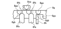
- FIG. 3 is a control block diagram illustrating a detailed configuration of a shift control system according to the first embodiment. It is explanatory drawing which shows the principal part cross section of the engagement clutch of Example 1. FIG. It is the figure which looked down the principal part of the engagement clutch shown to FIG. 3A from the upper direction to the downward direction, and shows the state just before meshing. It is the figure which looked down the principal part of the engagement clutch shown to FIG. 3A from the upper direction to the downward direction, and shows the chamfer part contact state in the middle of rotation synchronization.
- FIG. 3 is a flowchart illustrating a flow of a shift control process executed by the shift controller according to the first embodiment. It is a figure which shows an example of the target difference rotation speed setting map in Example 1.
- FIG. 3 is a flowchart illustrating a flow of a shift control process executed by the shift controller according to the first embodiment. It is a figure which shows an example of the target difference rotation speed setting map in Example 1.
- the characteristics of the accelerator opening, the target motor rotation speed, the engagement clutch target input rotation speed, the engagement clutch target output rotation speed, and the coupling sleeve position at the time of downshifting are described. It is a time chart which shows.
- Example 1 First, the configuration will be described.
- the configuration of the automatic transmission control device mounted on the electric vehicle (an example of a vehicle) in the first embodiment is divided into “overall system configuration”, “detailed configuration of transmission control system”, and “transmission control processing configuration”. To do.
- FIG. 1 shows a drive system configuration and a control system configuration of an electric vehicle to which the control device for an automatic transmission according to the first embodiment is applied.
- the overall system configuration of the first embodiment will be described below with reference to FIG.
- the drive system configuration of the electric vehicle includes a drive motor generator 2, an automatic transmission 3, and drive wheels 14.
- the drive motor generator 2 is a three-phase AC permanent magnet synchronous motor, and serves as a travel drive source for an electric vehicle.
- a positive torque (drive torque) command is output from the motor controller 28 to an inverter (not shown) from the motor controller 28, the drive motor generator 2 generates a drive torque using discharge power from a high-power battery (not shown).
- a drive operation is performed to drive the drive wheels 14 (power running).
- a negative torque (power generation torque) command is output from the motor controller 28 to the inverter, a power generation operation is performed to convert rotational energy from the drive wheels 14 into electric energy, and the generated power is charged to the high-power battery.
- Use electricity (regeneration) The motor shaft of the drive motor generator 2 is connected to the transmission input shaft 6 of the automatic transmission 3.
- the automatic transmission 3 is a constantly meshing stepped transmission that transmits power by one of two gear pairs having different gear ratios, and has a high gear stage (high speed stage) with a small reduction ratio and a low gear stage with a large reduction ratio. Two-speed transmission having (low speed) is used.
- the automatic transmission 3 is used for shifting when the motor power is output from the driving motor generator 2 through the transmission input shaft 6 and the transmission output shaft 7 in order, and a low-side transmission mechanism 8 for realizing a low speed stage. It is comprised by the high side transmission mechanism 9 which implement
- the transmission input shaft 6 and the transmission output shaft 7 are arranged in parallel.
- the low-side transmission mechanism 8 is for selecting a low-side transmission path when the motor power is output, and is disposed on the transmission output shaft 7.
- the low-side transmission mechanism 8 includes a gear 8a with respect to the transmission output shaft 7 such that a low-speed gear pair (gear 8a, gear 8b) is drivingly coupled between the transmission input shaft 6 and the transmission output shaft 7.
- An engagement clutch 8c engagement element that performs meshing engagement / release is configured.
- the low-speed gear pair includes a gear 8 a rotatably supported on the transmission output shaft 7, and a gear 8 b that meshes with the gear 8 a and rotates together with the transmission input shaft 6.
- the high-side transmission mechanism 9 is for selecting the high-side transmission path when the motor power is output, and is arranged on the transmission input shaft 6.
- the high-side transmission mechanism 9 includes a gear 9a with respect to the transmission input shaft 6 so that a high-speed gear pair (gear 9a, gear 9b) is drivingly coupled between the transmission input shaft 6 and the transmission output shaft 7.
- the friction clutch 9c engagement element that performs frictional engagement / release is configured.
- the high-speed gear pair includes a gear 9 a rotatably supported on the transmission input shaft 6 and a gear 9 b that meshes with the gear 9 a and rotates together with the transmission output shaft 7.
- the transmission output shaft 7 fixes a gear 11 and drives and couples a differential gear device 13 to the transmission output shaft 7 via a final drive gear set including the gear 11 and a gear 12 meshing with the gear 11. .
- a drive shaft 16 to which the drive wheels 14 are coupled is connected to the differential gear device 13.
- the motor power of the drive motor generator 2 that has reached the transmission output shaft 7 passes through the final drive gear sets 11 and 12 and the differential gear device 13 from the left and right drive shafts 16 to the drive wheels 14 (in FIG. 1). (Only one drive wheel is shown).
- a parking gear 17 is fixed to the transmission output shaft 7 on the opposite side of the gear 11, and a parking pole 18 provided in a transmission case (not shown) that can mesh with the parking gear 17 is disposed. That is, when the P range position is selected, the parking pole 18 is engaged with the parking gear 17 by the first electric actuator 41 that also serves as the engagement clutch 8c, so that the transmission output shaft 7 does not rotate. Fix it.
- the control system configuration of the electric vehicle includes a shift controller 21, a vehicle speed sensor 22, an accelerator opening sensor 23, a brake stroke sensor 24, a longitudinal acceleration sensor 25, a slider position sensor 26, and a sleeve position sensor 27.
- a motor controller 28, a brake controller 29, an integrated controller 30, a CAN communication line 31, and a range position switch 32 are provided.
- the transmission controller 21 is constituted by a microcomputer having a central processing unit (CPU), a read only memory (ROM), a random access memory (RAM), a backup memory, and an input / output interface circuit.
- the shift controller 21 outputs a shift request based on a shift map (not shown), and when the low gear stage in which the engagement clutch 8c is engaged and the friction clutch 9c is released is selected.
- a shift map not shown
- replacement control by releasing the engagement clutch 8c and frictional engagement of the friction clutch 9c is performed.
- the motor rotation speed sensor 33 is a sensor that detects the output rotation speed of the drive motor generator 2, and here detects the rotation speed of the transmission input shaft 6. That is, the rotational speed (motor rotational speed) of the drive motor generator 2 is the input rotational speed (hereinafter referred to as “clutch input rotational speed”) to the engaging elements (engagement clutch 8c, friction clutch 9c) of the automatic transmission 3.
- the clutch input rotational speed is detected by the motor rotational speed sensor 33.
- the transmission output rotational speed sensor 34 is a sensor for detecting the output rotational speed of the automatic transmission 3, and here detects the rotational speed of the transmission output shaft 7. That is, the rotational speed of the transmission output shaft 7 is the output rotational speed (hereinafter referred to as “clutch output rotational speed”) of the fastening elements (engagement clutch 8c, friction clutch 9c) of the automatic transmission 3, and the transmission The output rotational speed sensor 34 detects the clutch output rotational speed.
- FIG. 2 shows a detailed configuration of the shift control system of the first embodiment.
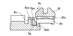
- FIG. 3 is an explanatory diagram of the engagement clutch according to the first embodiment.
- the detailed structure of the transmission control system of Example 1 is demonstrated.
- the shift control system of the electric vehicle control system includes an engagement clutch 8c, a friction clutch 9c, a parking gear 17, a drive motor generator 2, and a hydraulic brake 15. And a shift controller 21. That is, the engagement clutch 8c, the friction clutch 9c, the driving motor generator 2 and the hydraulic brake 15 are controlled, and controlled according to a command from the transmission controller 21 according to conditions.
- the engagement clutch 8c is a clutch by synchro meshing engagement.
- a clutch gear (first engagement member) 8d provided on the gear 8a and a clutch hub (second engagement) coupled to the transmission output shaft 7 are provided.
- Member) 8e and a coupling sleeve 8f are provided. Then, by driving the coupling sleeve 8 f by the first electric actuator 41, the clutch gear 8 d and the clutch hub 8 e are engaged and released through the coupling sleeve 8 f. Since the gear 8 a meshes with the gear 8 b that rotates together with the transmission input shaft 6, the clutch gear 8 d provided on the gear 8 a is connected to the transmission input shaft 6.
- the transmission controller 21 reads the value of the sleeve position sensor 27, and applies a current to the first electric actuator 41 so that the position of the coupling sleeve 8f is in the meshing engagement position or the release position.
- a position servo system by PID control is provided.
- the coupling sleeve 8f has a cylindrical shape with both ends open, and has a plurality of spline portions 8fa on the inner periphery of which clutch teeth (not shown) of the clutch gear 8d (see FIG. 1) are always fitted.
- the coupling sleeve 8f is supported so as to be movable in the axial direction which is the left-right direction in FIG. 3A while maintaining the state where the clutch teeth of the clutch gear 8d and the spline portion 8fa are fitted together.
- the axial movement of the coupling sleeve 8f is performed by driving the first electric actuator 41 (see FIG. 2).
- the clutch hub 8e is formed with a plurality of clutch teeth 8ea that can be fitted into a spline portion 8fa formed on the inner periphery of the coupling sleeve 8f on the outer periphery. That is, the clutch teeth 8ea of the clutch hub 8e can mesh with the clutch teeth (not shown) of the clutch gear 8d via the coupling sleeve 8f. Further, a synchronizer ring 8g is mounted on the outer periphery of the tapered cone portion 8eb so as to be movable in the axial direction.
- the synchronizer ring 8g is formed on the outer periphery with a plurality of sync teeth 8ga that can mesh with a plurality of spline portions 8fa of the coupling sleeve 8f, and a key groove 8gc that always engages with a key 8h provided on the coupling sleeve 8f.
- a gap is provided between the key 8h and the key groove 8gc, and the synchronizer ring 8g is configured to be movable relative to the coupling sleeve 8f in the rotational direction by the gap between the key 8h and the key groove 8gc. Has been.
- the engagement clutch 8c the synchronization operation by the synchronization mechanism when engaging and fastening from the released state will be described.
- the synchronizer ring 8g when meshing and engaging from the released state, the synchronizer ring 8g is pressed in the axial direction by the coupling sleeve 8f so as to be close to the clutch hub 8e.
- a frictional force is generated between the synchronizer ring 8g and the cone portion 8eb, and the coupling sleeve 8f and the clutch hub 8e are synchronously rotated and fastened by this frictional force.
- the coupling sleeve 8f is moved axially in the direction close to the clutch hub 8e together with the key 8h by the first electric actuator 41 (see FIG. 2) as shown in FIG. 3A, and the synchronizer ring 8g is moved. Press against the cone 8eb.
- both chamfer portions 8fb and 8gb come into contact as shown in FIG. 3C.
- the synchronizer ring 8g further pushes the cone portion 8eb to generate a friction torque, and the synchronizer ring 8g and the coupling sleeve 8f are synchronized with the clutch hub 8e.
- the synchronizer ring 8g rotates in the circumferential direction so that the spline portion 8fa meshes with the synchro teeth 8ga.
- the friction clutch 9c includes a driven plate 9d that rotates together with the gear 9a, and a drive plate 9e that rotates together with the transmission input shaft 6 (see FIG. 1). Then, the second electric actuator 42 drives the slider 9f that applies a pressing force to both the plates 9d and 9e, thereby engaging / releasing the friction.
- the transmission torque capacity of the friction clutch 9c is determined by the position of the slider 9f.
- the slider 9f is a screw mechanism, and is a mechanism that holds the position when the input of the second electric actuator 42 is 0 (zero).
- the speed change controller 21 reads the value of the slider position sensor 26 and supplies a current to the second electric actuator 42 so as to obtain a slider position where a desired transmission torque capacity can be obtained (for example, a position by PID control).
- a desired transmission torque capacity for example, a position by PID control).
- Servo system The friction clutch 9c rotates integrally with the transmission input shaft 6, drives the gear 9a to the transmission input shaft 6 when the clutch friction is engaged, and connects the gear 9a and the transmission input shaft 6 when the clutch is released. Disconnect the drive connection.
- the transmission output shaft 7 is prevented from rotating by engaging the parking pole 18 with the first electric actuator 41 that also serves as the engagement clutch 8c. Secure the case to the case. That is, the first electric actuator 41 manages the operation of the three positions of the engagement position of the engagement clutch 8c, the non-engagement position of the engagement clutch 8c, and the engagement position of the parking gear 17.
- the drive motor generator 2 is torque controlled or rotational speed controlled by a motor controller 28 that receives a command output from the speed change controller 21. That is, when the motor controller 28 inputs a motor torque capacity command, a torque upper limit command, and an input / output rotation synchronization command from the speed change controller 21, the drive motor generator 2 is controlled in torque or rotational speed based on these commands.
- the hydraulic brake 15 is controlled in pump-up operation for increasing the brake engagement force by a brake hydraulic pressure actuator (not shown) that receives a drive command from the brake controller 29 that receives a command output from the speed change controller 21.
- FIG. 4 shows a flow of a shift control process executed by the shift controller according to the first embodiment.
- each step representing the shift control processing configuration of the first embodiment will be described. This process is performed when a shift request is generated in the automatic transmission 3.
- step S1 it is determined whether or not a downshift request from the high gear stage to the low gear stage is output. If YES (downshift requested), the process proceeds to step S2. If NO (no downshift request), the shift control process shown in FIG. 4 is not executed and the process proceeds to the end.
- the downshift request is output when an operating point determined by the accelerator opening and the vehicle speed crosses the downshift line on a shift map (not shown) set based on the accelerator opening and the vehicle speed.
- step S2 following the determination that there is a downshift request in step S1, the coupling sleeve 8f is stroke driven by the first electric actuator 41 in the engagement clutch 8c. Then, the coupling sleeve 8f is displaced to a position just before meshing in the engagement clutch 8c, and the process proceeds to step S3.
- the “position immediately before meshing in the engagement clutch 8c” means that the tip position on the clutch hub side of the spline portion 8fa of the coupling sleeve 8f into which the clutch gear 8d is fitted is the position of the synchronizer ring 8g. This is the position immediately before overlapping the synchro tooth 8ga in the axial direction. That is, the position where the distance between the tip of the spline portion 8fa on the clutch hub side and the synchro tooth 8ga is a very small predetermined value is referred to as “position just before meshing in the engagement clutch 8c”.
- the position of the coupling sleeve 8 f is detected by the sleeve position sensor 27. Further, the coupling sleeve 8f that has reached the position just before meshing maintains this position.
- the target differential rotation speed for giving rotation is set, and the process proceeds to step S5.
- the “target differential rotational speed for giving a predetermined differential rotation” means the clutch tooth of the clutch hub 8e when the coupling sleeve 8f engaged with the clutch gear 8d engages with the clutch hub 8e by driving the stroke. 8ea and the spline portion 8fa of the coupling sleeve 8f are a slight difference in rotational speed that does not remain facing each other.
- the target differential rotation speed is set according to the map shown in FIG. 5, the vehicle speed detected by the vehicle speed sensor 22, and the vehicle acceleration or vehicle deceleration detected by the longitudinal acceleration sensor 25. That is, when the vehicle is accelerating, the rotational speed of the clutch gear 8d that is the clutch input rotational speed is set to a target differential rotational speed that is higher than the rotational speed of the clutch hub 8e that is the clutch output rotational speed. Furthermore, the target differential rotation speed to be set is increased as the vehicle acceleration increases.
- the rotational speed of the clutch gear 8d is set to a target differential rotational speed that is lower than the rotational speed of the clutch hub 8e. Furthermore, the target differential rotation speed to be set is increased as the vehicle deceleration increases.
- step S5 following the setting of the target differential rotation speed in step S4, the rotation speed (motor rotation speed) of the drive motor generator 2 that is the input rotation speed to the automatic transmission 3 is controlled, and the process proceeds to step S6.
- the input side rotation speed of the engagement clutch 8c varies, and the differential rotation (the difference between the rotation speed of the clutch gear 8d and the rotation speed of the clutch hub 8e) in the engagement clutch 8c is controlled.
- the motor rotation speed control is performed by feedback control based on detection values of the motor rotation speed sensor 33 and the transmission output rotation speed sensor 34.
- the position of the coupling sleeve 8 f is detected by the sleeve position sensor 27.
- FIG. 6 shows the accelerator opening, target motor speed, engagement clutch target input speed, engagement clutch target output speed, coupling sleeve during downshifting in an electric vehicle equipped with the control device of the first embodiment. It is a time chart which shows each characteristic of a position.
- the engagement clutch fastening operation of the first embodiment will be described with reference to FIG.
- Electric vehicle of Example 1 (an example of a vehicle) is to release the engagement clutch 8c, during travel of the friction clutch 9c in frictional engagement with the gear position, an accelerator opening is rapidly increased at time t 1 point shown in FIG. 6
- YES is determined in step S1 of the flowchart shown in FIG. 4, and the process proceeds to step S2.
- the coupling sleeve 8f of the engagement clutch 8c is stroke-driven by the first electric actuator 41, and the coupling sleeve 8f is displaced to a position immediately before meshing with the clutch hub 8e.
- step S3 the target rotational speed difference in the engagement clutch 8c, is set to a value to impart a predetermined differential rotation.
- the target motor rotational speed of drive motor generator 2 is set so as to achieve this target differential rotational speed in accordance with the target differential rotational speed.
- the motor rotation speed is automatically set to the transmission input rotation speed so that the motor rotation speed, which is the transmission input rotation speed, is higher than the transmission output rotation speed.
- the target motor speed is set so as to exceed a value obtained by integrating the gear ratio of the transmission 3. And it progresses to step S5 and performs motor rotation speed control.
- the actual rotational speed difference is the target rotational speed difference If it is determined that it has reached, the process proceeds from step S6 to step S7, where the coupling sleeve 8f is again stroke driven and starts to move toward the fastening position.
- the actual differential rotational speed is obtained by subtracting the rotational speed of the transmission output shaft 7 detected by the transmission output rotational speed sensor 34 from the rotational speed of the transmission input shaft 6 detected by the motor rotational speed sensor 33. calculate.
- the relative positional relationship between the spline portion 8fa and the clutch teeth 8ea continues to change until the coupling sleeve 8f is stroke driven and meshed with the clutch hub 8e, and the tip of the spline portion 8fa and the clutch teeth 8ea Collision with the tip can be avoided.
- the coupling sleeve 8f and the clutch hub 8e can be smoothly meshed with each other, and it is possible to prevent the incompatibility that the both do not mesh with each other.
- useless time such as redoing the fastening operation does not occur, and the shift time can be shortened.
- step S8 sets the target rotational speed difference in the engagement clutch 8c to zero.
- the target motor rotational speed of the drive motor generator 2 is set so as to achieve the target differential rotational speed in response to the target differential rotational speed being set to zero.
- the motor rotational speed which is the transmission input rotational speed
- the motor rotational speed is reduced to reduce the output rotational speed (transmission input rotational speed).
- the target motor speed is set so as to match the value obtained by integrating the gear ratio after the shift of the automatic transmission 3). Then, motor speed control is executed.
- the coupling sleeve 8f of the engagement clutch 8c is stroke-driven to a position just before engagement. is doing. That is, after the relative position between the coupling sleeve 8f meshed with the clutch gear 8d and the clutch hub 8e is set to a position just before meshing, the motor rotational speed control is performed so that the target differential rotational speed is achieved.
- the friction clutch 9c that is frictionally engaged is slip-engaged, and then the engagement clutch 8c is engaged.
- the engagement clutch 8c can be prepared for engagement without waiting for the completion of the slip engagement of the friction clutch 9c. Thereby, the time until the meshing engagement of the engagement clutch 8c is completed can be shortened, and the shift time can be further shortened.
- the clutch gear 8d that is the input rotational speed is set when the engagement clutch 8c is engaged. Is set to be higher than the rotational speed of the clutch hub 8e, which is the output rotational speed, and when the vehicle is decelerating, the rotational speed of the clutch gear 8d is lower than the rotational speed of the clutch hub 8e.
- the target differential rotation speed is set larger as the vehicle acceleration and the vehicle deceleration are larger.
- the relative movement speed between the tip of the spline portion 8fa of the coupling sleeve 8f and the tip of the clutch teeth 8ea of the clutch hub 8e is increased when the target differential rotation speed is larger, the meshing operation in the engagement clutch 8c is performed. Can be done quickly.
- a smaller target differential rotation speed can suppress a shock (fastening shock) when the coupling sleeve 8f is engaged with the clutch hub 8e.
- An automatic transmission 3 that is provided in a vehicle drive system and has an engagement clutch 8c that engages and engages when engaged as a fastening element, and a shift controller 21 that performs shift control of the automatic transmission 3 are provided.
- the engagement clutch 8c includes a first engagement member (clutch gear) 8d connected to the transmission input shaft 6 and a second engagement connected to the transmission output shaft 7 and engageable with the first engagement member 8d.
- the speed change controller 21 is configured to move the first engagement member 8d when the first engagement member 8d and the second engagement member 8e mesh with each other at the time of shifting (downshift) for engaging the engagement clutch 8c.
- a target differential rotational speed that gives a predetermined differential rotational speed is set between an input rotational speed that is the rotational speed and an output rotational speed that is the rotational speed of the second engagement member 8e.
- the speed change controller 21 moves the relative position between the first engagement member (clutch gear) 8d and the second engagement member (clutch hub) 8e at the time immediately before meshing at the time of shifting to engage the engagement clutch 8c. After that, the input rotational speed of the automatic transmission 3 is controlled so as to be the target differential rotational speed. Thereby, in addition to the effect (1), it is possible to shorten the time until the meshing engagement of the engagement clutch 8c is completed, and to further shorten the shift time.
- the transmission controller 21 sets the target differential rotational speed to a target differential rotational speed in which the input rotational speed is higher than the output rotational speed, or a target differential rotational speed in which the input rotational speed is lower than the output rotational speed. It was set as the structure which can be set to either. Thereby, in addition to the effect of (1) or (2) above, the direction of the action of the shock generated when the engagement clutch 8c is engaged (the engagement shock on the vehicle acceleration side or the engagement shock on the vehicle deceleration side) is controlled. It is possible to suppress a sense of incongruity during shifting.
- the shift controller 21 is configured to make the input rotation speed lower than the output rotation speed when the vehicle is decelerating at the time of shifting to engage the engagement clutch.
- the speed change controller 21 is configured to make the input speed higher than the output speed when the vehicle is accelerating at the time of shifting to engage the engagement clutch.
- the shift controller 21 is configured to set the target differential rotation speed in accordance with the magnitude of acceleration acting on the vehicle.
- the speed change controller 21 makes the input rotational speed lower than the output rotational speed and increases the target differential rotational speed as the vehicle deceleration increases at the time of shifting to engage the engagement clutch.
- the configuration Thereby, in addition to the effect of the above (6), the engagement clutch 8c can be fastened as needed while suppressing the occurrence of the fastening shock.
- the shift controller 21 is configured to increase the input rotation speed and the target differential rotation speed as the vehicle acceleration increases during a shift to engage the engagement clutch. It was. Thereby, in addition to the effect of (6) or (7) above, the engagement clutch 8c can be fastened as needed while suppressing the occurrence of fastening shock.
- Example 1 although the automatic transmission 3 showed the example which has the engagement clutch 8c and the friction clutch 9c, it is not restricted to this.
- the automatic transmission may have only an engagement clutch as a fastening element.
- the engagement clutch 8c has the synchronization mechanism.
- the present invention can be applied to a so-called dog clutch that does not have the synchronization mechanism.
- the clutch gear 8d as the first engagement member and the clutch hub 8e as the second engagement member are engaged with each other via the coupling sleeve 8f.
- the first engagement member and the second engagement member may directly mesh with each other.
- the “position immediately before meshing in the engagement clutch 8c” refers to the position immediately before the tip position on the clutch hub side of the spline portion 8fa of the coupling sleeve 8f overlaps the synchro teeth 8ga of the synchronizer ring 8g in the axial direction.
- the example of the position is shown, it is not limited to this.
- the position to be a value may be a “position just before meshing in the engagement clutch 8c”. In other words, the position where the first engagement member (or the member engaged with the first engagement member such as the coupling sleeve 8f) and the second engagement member are engaged in a very short time is “just before engagement in the engagement clutch 8c”. Position.
- the drive source is configured only by the drive motor generator 2
- the drive source may be a combination of a motor and an engine, or only the engine.
Landscapes
- Engineering & Computer Science (AREA)
- General Engineering & Computer Science (AREA)
- Mechanical Engineering (AREA)
- Control Of Transmission Device (AREA)
- Hydraulic Clutches, Magnetic Clutches, Fluid Clutches, And Fluid Joints (AREA)
- Electric Propulsion And Braking For Vehicles (AREA)
- Hybrid Electric Vehicles (AREA)
Abstract
Description
すなわち、入力側クラッチ歯と出力側クラッチ歯が対向した状態で回転数が同期してしまうと、クラッチ歯同士が接触し、噛み合うことができなかった。
そのため、一旦差回転を発生させて互いのクラッチ歯の位置を相対的にずらしてから噛み合い動作を再開する必要があった。これにより、締結完了までの時間がかかってしまうという問題が生じていた。
そして、前記係合クラッチは、変速機入力軸に連結した第1係合部材と、変速機出力軸に連結すると共に前記第1係合部材に噛み合い可能な第2係合部材と、を有している。
また、前記変速コントローラは、前記係合クラッチを締結させる変速時、前記第1係合部材と前記第2係合部材が噛み合うときに、前記第1係合部材の回転数である入力回転数と、前記第2係合部材の回転数である出力回転数との間に、所定の差回転を持たせる目標差回転数を設定する。
これにより、第1,第2係合部材が噛み合うタイミングにおいて、第1係合部材の歯と第2係合部材の歯の相対位置は変化し続ける。そのため、この第1係合部材の歯と第2係合部材の歯が対向していても、両者の歯の相対的な位置関係は速やかにずれることになる。このため、この第1係合部材の歯と第2係合部材の歯が対向したまま接触し続けることがなくなり、第1,第2係合部材が噛み合わない入り不の発生を防止することができる。
また、入り不の発生を防止することができるので、第1,第2係合部材の歯の相対的な位置をずらしてから噛み合い動作を再開する、といった手間が生じ得ない。この結果、係合クラッチの締結完了までの時間が長くなることを抑制することができる。
まず、構成を説明する。
実施例1における電気自動車(車両の一例)に搭載された自動変速機の制御装置の構成を、「全体システム構成」、「変速制御系の詳細構成」、「変速制御処理構成」に分けて説明する。
図1は、実施例1の自動変速機の制御装置が適用された電気自動車の駆動系構成と制御系構成を示す。以下、図1に基づき、実施例1の全体システム構成を説明する。
そして、この駆動用モータジェネレータ2のモータ軸は、自動変速機3の変速機入力軸6に接続される。
さらに、変速機出力軸7には、ギア11の反対側に、パーキングギア17が固定され、このパーキングギア17と噛み合い可能に図外の変速機ケースに設けられたパーキングポール18が配置される。つまり、Pレンジ位置の選択時、パーキングポール18を、係合クラッチ8cと兼用の第1電動アクチュエータ41によりパーキングギア17に噛み合わせることで、変速機出力軸7が回転しないように変速機ケースに固定する。
さらに、ダウンシフト時には、後述する変速制御処理を実行し、係合クラッチ8cの噛み合い係合を制御する。
図2は、実施例1の変速制御系の詳細構成を示す。図3は、実施例1の係合クラッチの説明図である。以下、図2及び図3に基づき、実施例1の変速制御系の詳細構成を説明する。
なお、変速機入力軸6と共に回転するギア8bにギア8aが噛み合っているため、ギア8aに設けたクラッチギア8dは、変速機入力軸6に連結している。すなわち、クラッチギア8dとクラッチハブ8eが噛み合い係合すると、変速機入力軸6と変速機出力軸7が連結される。
この係合クラッチ8cの噛み合い係合と解放は、カップリングスリーブ8fの位置によって決まる。そのため、変速コントローラ21は、スリーブ位置センサ27の値を読み込み、カップリングスリーブ8fの位置が噛み合い係合位置又は解放位置になるように第1電動アクチュエータ41に電流を与える第1位置サーボコントローラ51(例えば、PID制御による位置サーボ系)を備えている。そして、カップリングスリーブ8fがクラッチギア8d及びクラッチハブ8eの外周クラッチ歯の双方に噛合した図1に示す噛み合い位置にあるとき、ギア8aを変速機出力軸7に駆動連結する。一方、カップリングスリーブ8fが、図1に示す位置から軸線方向へ変位することでクラッチギア8d及びクラッチハブ8eの外周クラッチ歯の一方と非噛み合い位置にあるとき、ギア8aを変速機出力軸7から切り離す。
前記カップリングスリーブ8fは、両端が開放した円筒形状を呈しており、内周にクラッチギア8d(図1参照)の図示しないクラッチ歯が常時嵌め合わされる複数のスプライン部8faを有している。そして、このカップリングスリーブ8fは、クラッチギア8dのクラッチ歯とスプライン部8faが嵌め合わされた状態を維持しながら、図3Aにおいて左右方向である軸方向に移動可能に支持されている。ここで、カップリングスリーブ8fの軸方向の移動は、第1電動アクチュエータ41(図2参照)の駆動により成される。
さらに、このクラッチハブ8eには、テーパ状のコーン部8ebの外周に、軸方向に移動可能にシンクロナイザリング8gが装着されている。
前記係合クラッチ8cでは、解放状態から噛み合い係合する場合、カップリングスリーブ8fによって、シンクロナイザリング8gをクラッチハブ8eに近接するように軸方向に押圧する。これにより、シンクロナイザリング8gとコーン部8ebとの間に摩擦力が生じ、この摩擦力によりカップリングスリーブ8fとクラッチハブ8eとが同期回転して締結される。
すなわち、前記カップリングスリーブ8fを、第1電動アクチュエータ41(図2参照)により、図3Aに示すように、キー8hと共に、クラッチハブ8eに近接する方向へ軸方向に移動させ、シンクロナイザリング8gをコーン部8ebに押し付ける。
この回転同期が成立すると、シンクロナイザリング8gとコーン部8ebとの間の摩擦トルクが消滅する一方、カップリングスリーブ8fはキー8hから待機させたままさらに軸方向に移動する。これにより、カップリングスリーブ8fのスプライン部8faが、クラッチハブ8eのクラッチ歯8eaを押し分け、図3Eに示すように、クラッチハブ8eのクラッチ歯8eaと噛み合い、係合クラッチ8cは係合締結状態となる。
この摩擦クラッチ9cの伝達トルク容量は、スライダ9fの位置によって決まる。また、スライダ9fはネジ機構となっており、第2電動アクチュエータ42の入力が0(ゼロ)のとき、位置を保持する機構となっている。
変速コントローラ21は、スライダ位置センサ26の値を読み込み、所望の伝達トルク容量が得られるスライダ位置になるように第2電動アクチュエータ42に電流を与える第2位置サーボコントローラ52(例えば、PID制御による位置サーボ系)を備えている。
そして、摩擦クラッチ9cは、変速機入力軸6と一体に回転し、クラッチ摩擦締結のときギア9aを変速機入力軸6に駆動連結し、クラッチ解放のとき、ギア9aと変速機入力軸6の駆動連結を切り離す。
図4は、実施例1の変速コントローラにて実行される変速制御処理の流れを示す。以下、図4に基づき、実施例1の変速制御処理構成をあらわす各ステップについて説明する。
なお、この処理は、自動変速機3において、変速要求が発生したら行われる。
ここで、ダウンシフト要求は、アクセル開度と車速に基づいて設定された図示しない変速マップ上において、アクセル開度と車速で決まる運転点がダウンシフト線を横切ったときに出力される。
ここで、「係合クラッチ8cにおける噛み合い直前位置」とは、図3Bに示すように、クラッチギア8dが嵌りこんだカップリングスリーブ8fのスプライン部8faのクラッチハブ側先端位置が、シンクロナイザリング8gのシンクロ歯8gaと軸方向に重複する直前の位置である。つまり、スプライン部8faのクラッチハブ側先端とシンクロ歯8gaとの距離が、ごく僅かな所定値になる位置を、「係合クラッチ8cにおける噛み合い直前位置」とする。
ここで、カップリングスリーブ8fの位置は、スリーブ位置センサ27によって検出する。また、噛み合い直前位置に達したカップリングスリーブ8fは、この位置を維持する。
ここで、「所定の差回転を持たせる目標差回転数」とは、クラッチギア8dと噛み合っているカップリングスリーブ8fが、ストローク駆動してクラッチハブ8eと噛み合う際に、クラッチハブ8eのクラッチ歯8eaとカップリングスリーブ8fのスプライン部8faが対向したままにならない微少な回転数差である。つまり、クラッチ歯8eaとスプライン部8faが対向しても、速やかに両者の相対位置がずれて、クラッチ歯8eaとスプライン部8faが噛み合うことができる回転数差である。
また、この目標差回転数は、図5に示すマップと、車速センサ22によって検出される車速と、前後加速度センサ25によって検出される車両加速度又は車両減速度に応じて設定される。
すなわち、車両が加速している場合には、クラッチ入力回転数であるクラッチギア8dの回転数が、クラッチ出力回転数であるクラッチハブ8eの回転数よりも高くなる目標差回転数に設定する。さらに、車両加速度が大きいほど設定する目標差回転数を大きくする。
また、車両が減速している場合には、クラッチギア8dの回転数が、クラッチハブ8eの回転数よりも低くなる目標差回転数に設定する。さらに、車両減速度が大きいほど設定する目標差回転数を大きくする。
これにより、係合クラッチ8cの入力側回転数が変動し、係合クラッチ8cにおける差回転(クラッチギア8dの回転数とクラッチハブ8eの回転数の差)が制御される。なお、このモータ回転数制御は、モータ回転数センサ33及び変速機出力回転数センサ34の検出値に基づき、フィードバック制御により行う。
ここで、カップリングスリーブ8fの位置は、スリーブ位置センサ27によって検出する。
図6は、実施例1の制御装置を搭載した電気自動車において、ダウンシフト変速時のアクセル開度・目標モータ回転数・係合クラッチ目標入力回転数・係合クラッチ目標出力回転数・カップリングスリーブ位置の各特性を示すタイムチャートである。以下、図6に基づき、実施例1の係合クラッチ締結作用を説明する。
この変速指令の出力に伴い、図4に示すフローチャートのステップS1でYESと判断され、ステップS2へと進む。これにより、係合クラッチ8cのカップリングスリーブ8fは、第1電動アクチュエータ41によりストローク駆動され、カップリングスリーブ8fがクラッチハブ8eと噛み合い直前位置まで変位する。
なお、ここでは車両が加速しているので、変速機入力回転数であるモータ回転数が、変速機出力回転数よりも高くなるようにモータ回転数が出力回転数(変速機入力回転数に自動変速機3のギア比を積算した値)を上回るような目標モータ回転数を設定する。そして、ステップS5へと進み、モータ回転数制御を実行する。
ここで、実差回転数は、モータ回転数センサ33によって検出された変速機入力軸6の回転数から、変速機出力回転数センサ34によって検出された変速機出力軸7の回転数を差し引いて算出する。
つまり、カップリングスリーブ8fに対して、クラッチハブ8eは常に相対移動しているので、スプライン部8faとクラッチ歯8eaの相対的な位置関係は、時々刻々と変化する。
これにより、カップリングスリーブ8fがストローク駆動して、クラッチハブ8eに噛み合うまでの間にスプライン部8faとクラッチ歯8eaの相対的な位置関係は変化し続け、スプライン部8faの先端とクラッチ歯8eaの先端との衝突を回避することができる。この結果、カップリングスリーブ8fとクラッチハブ8eを円滑に噛み合わせることができ、両者が噛み合わない入り不の発生を防止することができる。
また、入り不が発生しないので、締結動作のやり直しといった無駄な時間が発生せず、変速時間の短縮化を図ることができる。
なお、ここでは変速機入力回転数であるモータ回転数が、変速機出力回転数よりも高くなる差回転に設定されていたので、モータ回転数を低減し、出力回転数(変速機入力回転数に自動変速機3の変速後のギア比を積算した値)に一致するような目標モータ回転数を設定する。そして、モータ回転数制御を実行する。
ここで、自動変速機3では、ダウンシフト要求が出力されると、まず、摩擦締結している摩擦クラッチ9cをスリップ締結し、その後、係合クラッチ8cの締結動作を行う。このとき、カップリングスリーブ8fを予め噛み合い直前位置までストローク駆動しておくことで、摩擦クラッチ9cのスリップ締結の完了を待たずに係合クラッチ8cの噛み合い準備を行うことができる。これにより、この係合クラッチ8cの噛み合い係合が完了するまでの時間を短縮することができ、変速時間のさらなる短縮化を図ることができる。
そのため、係合クラッチ8cが締結した際にショックが発生しても、車両加速時には、車両加速側の締結ショックになり、車両減速時には、車両減速側の締結ショックになる。このため、ショックが発生しても違和感を抑制することができる。
すなわち、車両加速度や車両減速度が大きいほど目標差回転数を大きく設定することで、係合クラッチ8cを締結しやすくして、変速速度を速めたいという要求に適切に応えることができる。また、車両加速度や車両減速度が小さいほど目標差回転数も小さく設定するので、係合クラッチ8cの噛み合い係合時に生じる締結ショックを抑制し、緩やかに加速又は減速する際に比較的感じやすい締結ショックを抑制することができる。
実施例1の自動変速機の制御装置にあっては、下記に挙げる効果を得ることができる。
前記係合クラッチ8cは、変速機入力軸6に連結した第1係合部材(クラッチギア)8dと、変速機出力軸7に連結すると共に前記第1係合部材8dに噛み合い可能な第2係合部材(クラッチハブ)8eと、を有し、
前記変速コントローラ21は、前記係合クラッチ8cを締結させる変速時(ダウンシフト時)、前記第1係合部材8dと前記第2係合部材8eが噛み合うときに、前記第1係合部材8dの回転数である入力回転数と、前記第2係合部材8eの回転数である出力回転数との間に、所定の差回転を持たせる目標差回転数を設定する構成とした。
これにより、係合クラッチ締結時の入り不の発生を防止し、締結完了までの時間が長くなることを抑制できる。
これにより、上記(1)の効果に加え、係合クラッチ8cの噛み合い係合が完了するまでの時間を短縮することができ、変速時間のさらなる短縮化を図ることができる。
これにより、上記(1)又は(2)の効果に加え、係合クラッチ8cを締結した際に生じるショックの作用方向(車両加速側の締結ショック又は車両減速側の締結ショック)の制御を行うことができ、変速時の違和感を抑制することができる。
これにより、上記(3)の効果に加え、係合クラッチ締結時の締結ショックを車両減速側の締結ショックとすることができ、違和感を抑制することができる。
これにより、上記(3)又は(4)の効果に加え、係合クラッチ締結時の締結ショックを車両加速側の締結ショックとすることができ、違和感を抑制することができる。
これにより、上記(1)~(5)のいずれかの効果に加え、係合クラッチ8cを締結する際の締結しやすさと、発生する締結ショックの大きさとをバランスよく制御することができる。
これにより、上記(6)の効果に加え、締結ショックの発生を抑制しつつ、必要に応じて速やかに係合クラッチ8cを締結することができる。
これにより、上記(6)又は(7)の効果に加え、締結ショックの発生を抑制しつつ、必要に応じて速やかに係合クラッチ8cを締結することができる。
つまり、第1係合部材(又はカップリングスリーブ8fのような第1係合部材に噛み合っている部材)と第2係合部材が、ごく短時間で噛み合う位置を「係合クラッチ8cにおける噛み合い直前位置」とする。
Claims (8)
- 車両の駆動系に設けられ、締結要素として締結時に噛み合い係合する係合クラッチを有する自動変速機と、前記自動変速機の変速制御を行う変速コントローラと、を備えた自動変速機の制御装置において、
前記係合クラッチは、変速機入力軸に連結した第1係合部材と、変速機出力軸に連結すると共に前記第1係合部材に噛み合い可能な第2係合部材と、を有し、
前記変速コントローラは、前記係合クラッチを締結させる変速時、前記第1係合部材と前記第2係合部材が噛み合うときに、前記第1係合部材の回転数である入力回転数と、前記第2係合部材の回転数である出力回転数との間に、所定の差回転を持たせる目標差回転数を設定する
ことを特徴とする自動変速機の制御装置。 - 請求項1に記載された自動変速機の制御装置において、
前記変速コントローラは、前記係合クラッチを締結させる変速時、前記第1係合部材と前記第2係合部材の相対位置を噛み合う直前位置にしてから、前記目標差回転数になるように前記自動変速機の入力回転数を制御する
ことを特徴とする自動変速機の制御装置。 - 請求項1又は請求項2に記載された自動変速機の制御装置において、
前記変速コントローラは、前記目標差回転数を、前記入力回転数が前記出力回転数より高い目標差回転数、又は、前記入力回転数が前記出力回転数より低い目標差回転数のいずれかに設定可能とする
ことを特徴とする自動変速機の制御装置。 - 請求項3に記載された自動変速機の制御装置において、
前記変速コントローラは、前記係合クラッチを締結させる変速時、車両が減速している場合には、前記入力回転数を前記出力回転数よりも低くする
ことを特徴とする自動変速機の制御装置。 - 請求項3又は4に記載された自動変速機の制御装置において、
前記変速コントローラは、前記係合クラッチを締結させる変速時、車両が加速している場合には、前記入力回転数を前記出力回転数よりも高くする
ことを特徴とする自動変速機の制御装置。 - 請求項1から請求項5のいずれか一項に記載された自動変速機の制御装置において、
前記変速コントローラは、車両に作用する加速度の大きさに応じて前記目標差回転数の大きさを設定する
ことを特徴とする自動変速機の制御装置。 - 請求項6に記載された自動変速機の制御装置において、
前記変速コントローラは、前記係合クラッチを締結させる変速時、車両減速度が大きいほど、前記入力回転数を前記出力回転数よりも低くし、且つ、前記目標差回転数を大きくする
ことを特徴とする自動変速機の制御装置。 - 請求項6又は7に記載された自動変速機の制御装置において、
前記変速コントローラは、前記係合クラッチを締結させる変速時、車両加速度が大きいほど、前記入力回転数を前記出力回転数よりも高くし、且つ、前記目標差回転数を大きくする
ことを特徴とする自動変速機の制御装置。
Priority Applications (4)
| Application Number | Priority Date | Filing Date | Title |
|---|---|---|---|
| JP2015546597A JP6056985B2 (ja) | 2013-11-06 | 2014-10-23 | 自動変速機の制御装置 |
| CN201480056887.4A CN105637265B (zh) | 2013-11-06 | 2014-10-23 | 自动变速机的控制装置 |
| US15/025,290 US9695933B2 (en) | 2013-11-06 | 2014-10-23 | Automatic transmission control device |
| EP14860834.2A EP3067589B1 (en) | 2013-11-06 | 2014-10-23 | Automatic transmission control device |
Applications Claiming Priority (2)
| Application Number | Priority Date | Filing Date | Title |
|---|---|---|---|
| JP2013-230680 | 2013-11-06 | ||
| JP2013230680 | 2013-11-06 |
Publications (1)
| Publication Number | Publication Date |
|---|---|
| WO2015068584A1 true WO2015068584A1 (ja) | 2015-05-14 |
Family
ID=53041366
Family Applications (1)
| Application Number | Title | Priority Date | Filing Date |
|---|---|---|---|
| PCT/JP2014/078191 Ceased WO2015068584A1 (ja) | 2013-11-06 | 2014-10-23 | 自動変速機の制御装置 |
Country Status (5)
| Country | Link |
|---|---|
| US (1) | US9695933B2 (ja) |
| EP (1) | EP3067589B1 (ja) |
| JP (1) | JP6056985B2 (ja) |
| CN (1) | CN105637265B (ja) |
| WO (1) | WO2015068584A1 (ja) |
Cited By (6)
| Publication number | Priority date | Publication date | Assignee | Title |
|---|---|---|---|---|
| JP2017180782A (ja) * | 2016-03-31 | 2017-10-05 | 本田技研工業株式会社 | 自動変速機の変速制御装置 |
| WO2018124220A1 (ja) * | 2016-12-27 | 2018-07-05 | アイシン・エーアイ株式会社 | 動力伝達制御装置 |
| WO2018124219A1 (ja) * | 2016-12-27 | 2018-07-05 | アイシン・エーアイ株式会社 | 動力伝達制御装置 |
| EP3426948A1 (en) * | 2016-03-06 | 2019-01-16 | Dana Belgium N.V. | Driveline for a vehicle including an electric drive motor and a powershift transmission having at least two transmission stages |
| JP2020001502A (ja) * | 2018-06-27 | 2020-01-09 | 日野自動車株式会社 | ハイブリッド自動車の変速支援方法及び装置 |
| JP2022146837A (ja) * | 2021-03-22 | 2022-10-05 | 株式会社イケヤフォ-ミュラ | 噛み合いクラッチ機構、摩擦クラッチ機構、及び2段変速装置 |
Families Citing this family (5)
| Publication number | Priority date | Publication date | Assignee | Title |
|---|---|---|---|---|
| NL2018971B1 (en) * | 2017-05-24 | 2018-12-07 | Punch Powertrain Nv | a shifting method for a transmission, a transmission system, a computer program product, and a vehicle. |
| JP7492896B2 (ja) * | 2020-10-12 | 2024-05-30 | カワサキモータース株式会社 | ギヤ変速機付き車両の制御装置及び制御方法 |
| CN112648308B (zh) * | 2020-12-30 | 2022-04-29 | 蜂巢传动科技河北有限公司 | 基于离合器调节同步器两端速差的控制方法、装置及系统 |
| DE102021213655A1 (de) * | 2021-12-02 | 2023-06-07 | Zf Friedrichshafen Ag | Kopplungsvorrichtung für ein Kraftfahrzeug |
| CN115789238B (zh) * | 2022-10-28 | 2026-04-10 | 重庆青山工业有限责任公司 | 自动变速器离合器输入转速调速的调度控制方法 |
Citations (7)
| Publication number | Priority date | Publication date | Assignee | Title |
|---|---|---|---|---|
| JP2001090826A (ja) | 1999-09-22 | 2001-04-03 | Hitachi Ltd | 自動変速機の制御装置 |
| JP2005114107A (ja) * | 2003-10-10 | 2005-04-28 | Hitachi Ltd | 自動車の変速方法,自動車の変速装置,自動車用変速機の制御装置,自動車の変速装置のアクチュエータ制御装置 |
| JP2006038136A (ja) * | 2004-07-28 | 2006-02-09 | Toyota Motor Corp | 駆動装置 |
| JP2007278487A (ja) * | 2006-04-12 | 2007-10-25 | Mitsubishi Electric Corp | 変速装置 |
| JP2008075718A (ja) * | 2006-09-20 | 2008-04-03 | Mitsubishi Fuso Truck & Bus Corp | 車両用変速制御装置 |
| WO2012127655A1 (ja) * | 2011-03-23 | 2012-09-27 | トヨタ自動車株式会社 | 車両用駆動装置 |
| JP2014105826A (ja) * | 2012-11-29 | 2014-06-09 | Fuji Heavy Ind Ltd | クラッチ制御装置 |
Family Cites Families (5)
| Publication number | Priority date | Publication date | Assignee | Title |
|---|---|---|---|---|
| US5425284A (en) | 1993-09-07 | 1995-06-20 | Eaton Corporation | Automated mechanical transmission control system/method |
| JP3685149B2 (ja) * | 2002-04-25 | 2005-08-17 | トヨタ自動車株式会社 | 車両用駆動制御装置 |
| WO2010119504A1 (ja) * | 2009-04-14 | 2010-10-21 | トヨタ自動車株式会社 | 車両の駆動制御装置 |
| US8734294B2 (en) * | 2010-11-22 | 2014-05-27 | Toyota Jidosha Kabushiki Kaisha | Control device of vehicle power transmission device |
| GB2495564B (en) | 2011-11-22 | 2014-11-05 | Jaguar Land Rover Ltd | A method and a control unit for controlling the engagement of an input gear with an output gear |
-
2014
- 2014-10-23 EP EP14860834.2A patent/EP3067589B1/en active Active
- 2014-10-23 JP JP2015546597A patent/JP6056985B2/ja active Active
- 2014-10-23 CN CN201480056887.4A patent/CN105637265B/zh active Active
- 2014-10-23 WO PCT/JP2014/078191 patent/WO2015068584A1/ja not_active Ceased
- 2014-10-23 US US15/025,290 patent/US9695933B2/en active Active
Patent Citations (7)
| Publication number | Priority date | Publication date | Assignee | Title |
|---|---|---|---|---|
| JP2001090826A (ja) | 1999-09-22 | 2001-04-03 | Hitachi Ltd | 自動変速機の制御装置 |
| JP2005114107A (ja) * | 2003-10-10 | 2005-04-28 | Hitachi Ltd | 自動車の変速方法,自動車の変速装置,自動車用変速機の制御装置,自動車の変速装置のアクチュエータ制御装置 |
| JP2006038136A (ja) * | 2004-07-28 | 2006-02-09 | Toyota Motor Corp | 駆動装置 |
| JP2007278487A (ja) * | 2006-04-12 | 2007-10-25 | Mitsubishi Electric Corp | 変速装置 |
| JP2008075718A (ja) * | 2006-09-20 | 2008-04-03 | Mitsubishi Fuso Truck & Bus Corp | 車両用変速制御装置 |
| WO2012127655A1 (ja) * | 2011-03-23 | 2012-09-27 | トヨタ自動車株式会社 | 車両用駆動装置 |
| JP2014105826A (ja) * | 2012-11-29 | 2014-06-09 | Fuji Heavy Ind Ltd | クラッチ制御装置 |
Cited By (15)
| Publication number | Priority date | Publication date | Assignee | Title |
|---|---|---|---|---|
| US10851879B2 (en) | 2016-03-06 | 2020-12-01 | Dana Belgium N.V. | Driveline for a vehicle including an electric drive motor and a powershift transmission having at least two transmission stages |
| US11236809B2 (en) | 2016-03-06 | 2022-02-01 | Dana Belgium N.V. | Driveline for a vehicle including an electric drive motor and a powershift transmission having at least two transmission stages |
| EP3426948A1 (en) * | 2016-03-06 | 2019-01-16 | Dana Belgium N.V. | Driveline for a vehicle including an electric drive motor and a powershift transmission having at least two transmission stages |
| CN107269824A (zh) * | 2016-03-31 | 2017-10-20 | 本田技研工业株式会社 | 自动变速器的变速控制装置 |
| JP2017180782A (ja) * | 2016-03-31 | 2017-10-05 | 本田技研工業株式会社 | 自動変速機の変速制御装置 |
| US10344850B2 (en) | 2016-03-31 | 2019-07-09 | Honda Motor Co., Ltd. | Shift control apparatus of automatic transmission |
| WO2018124219A1 (ja) * | 2016-12-27 | 2018-07-05 | アイシン・エーアイ株式会社 | 動力伝達制御装置 |
| CN110100123B (zh) * | 2016-12-27 | 2020-11-06 | 爱信艾达株式会社 | 动力传递控制装置 |
| CN110100123A (zh) * | 2016-12-27 | 2019-08-06 | 爱信艾达株式会社 | 动力传递控制装置 |
| US11092235B2 (en) | 2016-12-27 | 2021-08-17 | Aisin Aw Co., Ltd. | Power transmission control device |
| WO2018124220A1 (ja) * | 2016-12-27 | 2018-07-05 | アイシン・エーアイ株式会社 | 動力伝達制御装置 |
| US11603924B2 (en) | 2016-12-27 | 2023-03-14 | Aisin Aw Co., Ltd. | Power transmission control device |
| JP2020001502A (ja) * | 2018-06-27 | 2020-01-09 | 日野自動車株式会社 | ハイブリッド自動車の変速支援方法及び装置 |
| JP7090984B2 (ja) | 2018-06-27 | 2022-06-27 | 日野自動車株式会社 | ハイブリッド自動車の変速支援方法及び装置 |
| JP2022146837A (ja) * | 2021-03-22 | 2022-10-05 | 株式会社イケヤフォ-ミュラ | 噛み合いクラッチ機構、摩擦クラッチ機構、及び2段変速装置 |
Also Published As
| Publication number | Publication date |
|---|---|
| EP3067589B1 (en) | 2020-02-26 |
| CN105637265A (zh) | 2016-06-01 |
| CN105637265B (zh) | 2018-10-09 |
| JP6056985B2 (ja) | 2017-01-11 |
| JPWO2015068584A1 (ja) | 2017-03-09 |
| EP3067589A1 (en) | 2016-09-14 |
| US9695933B2 (en) | 2017-07-04 |
| US20160230881A1 (en) | 2016-08-11 |
| EP3067589A4 (en) | 2017-04-26 |
Similar Documents
| Publication | Publication Date | Title |
|---|---|---|
| JP6056985B2 (ja) | 自動変速機の制御装置 | |
| JP5854156B2 (ja) | 電動車両の変速制御装置 | |
| CN104870868A (zh) | 电动车辆的变速控制装置 | |
| US20150375750A1 (en) | Automatic transmission control device | |
| JP6061039B2 (ja) | 車両用自動変速機 | |
| JP6663095B2 (ja) | 車両用自動変速機 | |
| JP6248530B2 (ja) | 電動車両の変速制御装置 | |
| WO2014147918A1 (ja) | 車両の変速制御装置 | |
| JP6442736B2 (ja) | 車両用自動変速機 | |
| JP2015087001A (ja) | 自動変速機の制御装置 | |
| WO2014136364A1 (ja) | 車両の変速制御装置 | |
| JP6070294B2 (ja) | 車両の変速制御装置 | |
| US9874278B2 (en) | Automatic transmission control device | |
| JP2015090197A (ja) | パーキングアクチュエータの制御装置 | |
| WO2022118896A1 (ja) | 車両用駆動装置 | |
| JP5367445B2 (ja) | 車両の動力伝達制御装置 | |
| JP6089802B2 (ja) | 車両の変速制御装置 | |
| JP6209834B2 (ja) | 自動変速機の制御装置 | |
| JP2022087708A (ja) | 車両用駆動装置 | |
| JP2014173672A (ja) | 車両の変速制御装置 | |
| JP2013181616A (ja) | パーキングロック機構を有する動力伝達装置及びパーキングロック方法 | |
| JP2015113866A (ja) | 車両用自動変速機 | |
| JP2015113865A (ja) | 車両用自動変速機 |
Legal Events
| Date | Code | Title | Description |
|---|---|---|---|
| 121 | Ep: the epo has been informed by wipo that ep was designated in this application |
Ref document number: 14860834 Country of ref document: EP Kind code of ref document: A1 |
|
| WWE | Wipo information: entry into national phase |
Ref document number: 15025290 Country of ref document: US |
|
| ENP | Entry into the national phase |
Ref document number: 2015546597 Country of ref document: JP Kind code of ref document: A |
|
| REEP | Request for entry into the european phase |
Ref document number: 2014860834 Country of ref document: EP |
|
| WWE | Wipo information: entry into national phase |
Ref document number: 2014860834 Country of ref document: EP |
|
| NENP | Non-entry into the national phase |
Ref country code: DE |