WO2015068644A1 - 検査装置 - Google Patents
検査装置 Download PDFInfo
- Publication number
- WO2015068644A1 WO2015068644A1 PCT/JP2014/079026 JP2014079026W WO2015068644A1 WO 2015068644 A1 WO2015068644 A1 WO 2015068644A1 JP 2014079026 W JP2014079026 W JP 2014079026W WO 2015068644 A1 WO2015068644 A1 WO 2015068644A1
- Authority
- WO
- WIPO (PCT)
- Prior art keywords
- collision
- unit
- calculation unit
- hammer
- inspection apparatus
- Prior art date
- Legal status (The legal status is an assumption and is not a legal conclusion. Google has not performed a legal analysis and makes no representation as to the accuracy of the status listed.)
- Ceased
Links
Images


Classifications
-
- G—PHYSICS
- G01—MEASURING; TESTING
- G01N—INVESTIGATING OR ANALYSING MATERIALS BY DETERMINING THEIR CHEMICAL OR PHYSICAL PROPERTIES
- G01N3/00—Investigating strength properties of solid materials by application of mechanical stress
- G01N3/30—Investigating strength properties of solid materials by application of mechanical stress by applying a single impulsive force, e.g. by falling weight
-
- G—PHYSICS
- G01—MEASURING; TESTING
- G01N—INVESTIGATING OR ANALYSING MATERIALS BY DETERMINING THEIR CHEMICAL OR PHYSICAL PROPERTIES
- G01N29/00—Investigating or analysing materials by the use of ultrasonic, sonic or infrasonic waves; Visualisation of the interior of objects by transmitting ultrasonic or sonic waves through the object
- G01N29/04—Analysing solids
- G01N29/045—Analysing solids by imparting shocks to the workpiece and detecting the vibrations or the acoustic waves caused by the shocks
-
- G—PHYSICS
- G01—MEASURING; TESTING
- G01N—INVESTIGATING OR ANALYSING MATERIALS BY DETERMINING THEIR CHEMICAL OR PHYSICAL PROPERTIES
- G01N29/00—Investigating or analysing materials by the use of ultrasonic, sonic or infrasonic waves; Visualisation of the interior of objects by transmitting ultrasonic or sonic waves through the object
- G01N29/44—Processing the detected response signal, e.g. electronic circuits specially adapted therefor
- G01N29/46—Processing the detected response signal, e.g. electronic circuits specially adapted therefor by spectral analysis, e.g. Fourier analysis or wavelet analysis
-
- G—PHYSICS
- G01—MEASURING; TESTING
- G01N—INVESTIGATING OR ANALYSING MATERIALS BY DETERMINING THEIR CHEMICAL OR PHYSICAL PROPERTIES
- G01N33/00—Investigating or analysing materials by specific methods not covered by groups G01N1/00 - G01N31/00
- G01N33/02—Food
- G01N33/08—Eggs, e.g. by candling
-
- G—PHYSICS
- G01—MEASURING; TESTING
- G01N—INVESTIGATING OR ANALYSING MATERIALS BY DETERMINING THEIR CHEMICAL OR PHYSICAL PROPERTIES
- G01N2203/00—Investigating strength properties of solid materials by application of mechanical stress
- G01N2203/003—Generation of the force
- G01N2203/0032—Generation of the force using mechanical means
- G01N2203/0039—Hammer or pendulum
-
- G—PHYSICS
- G01—MEASURING; TESTING
- G01N—INVESTIGATING OR ANALYSING MATERIALS BY DETERMINING THEIR CHEMICAL OR PHYSICAL PROPERTIES
- G01N2291/00—Indexing codes associated with group G01N29/00
- G01N2291/26—Scanned objects
- G01N2291/269—Various geometry objects
- G01N2291/2698—Other discrete objects, e.g. bricks
Definitions
- the present invention relates to an inspection apparatus including a hammer unit that taps an object and a detection unit that detects vibration generated when the hammer unit hits the object.
- an inspection apparatus including a hammer unit that taps an object (for example, a chicken egg) and a detection unit that detects vibration generated by the hammer unit hitting the object is known (for example, Patent Documents). 1). Such an inspection apparatus inspects the object based on the sound signal detected by the detection unit.
- such an inspection apparatus inspects an object by converting a sound signal detected by a detection unit into a spectrum intensity of a frequency band.
- the inspection accuracy may decrease due to variations in the size of the object or changes in the inspection environment.
- an object of the present invention is to provide an inspection apparatus capable of improving inspection accuracy.
- the inspection apparatus includes a hammer unit that taps an object, a detection unit that detects vibration caused by the hammer unit hitting the object, and a vibration of the hammer unit based on the vibration detected by the detection unit.
- a calculation unit that calculates the number of times the hammer unit has collided with the object with respect to a single hitting operation, and a determination unit that determines the quality of the object based on the number of times the calculation unit calculates.
- the detection unit detects vibration generated when the hammer unit strikes the object.
- the hammer part bounces with the object, whereas when the object is an abnormal egg (such as a cracked egg), the object Since the object absorbs the impact of the hammer part, the hammer part is suppressed from bouncing on the object.
- the calculation unit calculates the number of times the hammer unit has bounced and collided with the object with respect to a single hitting operation of the hammer unit.
- the quality of the object is judged based on the number of times of calculation. Thereby, inspection accuracy can be improved.
- the detection unit may be a piezoelectric element that is attached to the tip of the hammer unit.
- the detection unit is a piezoelectric element attached to the tip of the hammer unit, the vibration detected by the detection unit can be suppressed from including noise such as environmental noise. Thereby, inspection accuracy can be improved effectively.
- the calculation unit includes a first collision calculation unit that calculates the time of the first collision, and a second collision calculation unit that calculates the presence or absence of the second collision,
- the first collision calculation unit calculates the largest vibration intensity among the vibrations detected by the detection unit as the first collision
- the second collision calculation unit calculates the first collision within a set time from the first collision.
- the largest vibration intensity is detected and the vibration intensity is larger than the set value, it is determined that there is a second collision.
- the vibration intensity is smaller than the set value, there is no second collision.
- the determination may be such that the determination unit determines that the object is NO when the second collision calculation unit determines that there is no second collision.
- the calculation unit further includes a third collision calculation unit that calculates the presence or absence of a third collision, and the third collision calculation unit includes two second collision calculation units.
- the third collision calculation unit includes two second collision calculation units.
- the calculation unit calculates the number of times that the vibration intensity detected by the detection unit exceeds a set value as the number of collisions
- the determination unit is the calculation unit.
- the configuration may be such that when the calculated number of collisions is greater than or equal to the set number of times, the object is determined to be good, and when the number of collisions calculated by the calculation unit is less than the set number of times, the target is determined to be no. .
- the inspection apparatus according to the present invention has an excellent effect that the inspection accuracy can be improved.
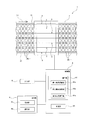
- FIG. 1 shows a schematic overall view of an inspection apparatus according to an embodiment of the present invention.
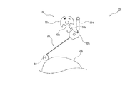
- FIG. 2 shows an overall plan view of the percussion unit according to the embodiment.
- FIG. 3 shows a schematic overall view of the consultation section according to the embodiment.
- FIG. 4 shows a schematic overall view for explaining the operation of the percussion unit according to the embodiment.
- FIG. 5 shows a schematic overall view for explaining the operation of the percussion unit according to the embodiment.
- FIG. 6 shows a flowchart of the inspection according to the embodiment.
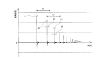
- FIG. 7 is a time-vibration intensity graph for explaining the inspection according to the embodiment, and shows a graph in which a normal product is inspected.
- FIG. 8 is a time-vibration intensity graph for explaining the inspection according to the embodiment, in which an abnormal product is inspected.
- FIG. 7 is a time-vibration intensity graph for explaining the inspection according to the embodiment, and shows a graph in which a normal product is inspected.
- FIG. 8 is a time-vib
- FIG. 9 is a time-vibration intensity graph for explaining an inspection according to another embodiment of the present invention, and shows a graph in which a normal product is inspected.
- FIG. 10 is a time-vibration intensity graph for explaining the inspection according to the embodiment, and shows a graph in which an abnormal product is inspected.
- the inspection apparatus according to the present embodiment is an egg crack inspection apparatus that uses eggs (particularly chicken eggs) as an object to be inspected and inspects for the presence or absence of cracks in the eggs.
- the dimensional ratio in the drawing does not necessarily match the actual dimensional ratio.
- an inspection apparatus 1 As shown in FIG. 1, an inspection apparatus 1 according to the present embodiment is arranged above a transport apparatus 2 that transports an egg 100 along the transport direction D ⁇ b> 1 and is transported to the transport apparatus 2.
- a plurality of consultation units 3 for consulting the eggs 100 and a control unit 4 for controlling the apparatus are provided.
- the inspection apparatus 1 includes an input unit 5 for inputting information related to the inspection and an output unit 6 for outputting information related to the inspection.
- the transport device 2 is disposed along a pair of travel bodies (for example, chains or belts) 21 and 21 that travel so as to rotate endlessly, and a horizontal direction orthogonal to the transport direction D1.
- the conveying apparatus 2 is conveying the egg 100 mounted ranging over the rotary bodies 22 and 22 along the conveyance direction D1, rotating.
- the rotating body 22 includes a concave holding portion 22a for holding the egg 100.
- a plurality of holding portions 22 a are arranged in parallel along the longitudinal direction of the rotating body 22. Accordingly, the transport device 2 aligns and transports the eggs 100 along the transport direction D1, and a plurality (six in this embodiment) of the transport rows are arranged in parallel in the longitudinal direction of the rotating body 22. .
- the percussion unit 3 is arranged for each conveying row of the eggs 100, and in this embodiment, six are provided. Specifically, the plurality of consultation units 3 are arranged in parallel in a direction orthogonal to the transport direction D1.
- the percussion unit 3 includes a plurality of percussion units 30 for hitting the egg 100 as shown in FIGS.
- the percussion unit 30 includes a hammer unit 31 that taps the egg 100, a drive unit 32 that operates the hammer unit 31, and a detection unit 33 that detects vibration generated when the hammer unit 31 hits the egg 100.
- a plurality of percussion units 30 are arranged in parallel along the transport direction D1. In the present embodiment, ten percussion units 30 are provided for one percussion unit 3.
- the hammer portion 31 includes a long body 31 a that is formed in a long shape, and a contact portion 31 b that is connected to the tip of the long body 31 a and contacts the egg 100.
- the hammer portion 31 is configured such that when the normal egg 100 is struck, the elongated body 31a is bent so that the contact portion 31b bounces on the surface of the egg 100 and collides a plurality of times. Yes.
- the long body 31 a is formed in a round bar shape, and has elasticity so that it becomes when the hammer portion 31 hits the egg 100.
- the long body 31a is composed of a carbon fiber rod, a glass solid rod, or a metal rod such as a Ni—Ti alloy.
- the contact part 32b is comprised with resin, such as a polyacetal.
- the drive unit 32 is connected to a rotating cam 32a, a rod-shaped contact 32b whose tip is in contact with the cam 32a, a proximal end of the elongated body 31a, and a proximal end of the contact 32b, respectively, and a hammer portion. 31 and a rotating part 32c for rotating the contact 32b around the axis.
- the drive unit 32 is configured so that the urging body 32d such as a spring that urges the abutting portion 31b of the hammer portion 31 toward the egg 100 and the contact 32b come into contact with each other, whereby the hammer 31 and the contact 32b are brought into contact with each other.
- a restricting portion 32e that restricts rotation by a predetermined angle or more.
- the cam 32a is provided with a sliding contact portion 32f in sliding contact with the contact 32b on the outer peripheral portion in order to hold the hammer portion 31 at a standby position (see FIG. 3) for separating the hammer portion 31 from the egg 100 and waiting. Further, the cam 32a has a recess 32g for releasing contact with the contact 32b so that the hammer portion 31 strikes the egg 100 (see FIG. 4), and returns the hammer portion 31 to the standby position (see FIG. 5). And a locking piece 32h for locking the contact 32b.
- the detecting unit 33 is a piezoelectric element that electrically detects vibration by converting externally applied vibration into a voltage by a piezoelectric effect. And the detection part 33 is attached to the front-end
- the control unit 4 includes a calculation unit 41 that calculates the number of times the hammer unit 31 collides with the egg 100 with respect to one hitting operation of the hammer unit 31 based on the vibration detected by the detection unit 33.
- the control unit 4 includes a determination unit 42 that determines the quality of the egg 100 based on the number of times the calculation unit 41 calculates.
- the calculation unit 41 includes a first collision calculation unit 41a that calculates the time when the hammer unit 31 collides with the egg 100 for the first time.
- the calculation unit 41 also includes a second collision calculation unit 41b that calculates the presence / absence of the second collision and a third collision that calculates the presence / absence of the third collision when the hammer unit 31 bounces on the surface of the egg 100.
- an arithmetic unit 41c an arithmetic unit 41c.
- the output unit 6 displays the vibration information detected by the detection unit 33 and the determination result determined by the determination unit 42 on the screen, and the selection for selecting the eggs 100 based on the determination result of the determination unit 42.
- the sorting unit 62 sorts the egg 100 determined to be a normal product and the egg 100 determined to be an abnormal product, and transports them to different downstream devices.
- the configuration of the inspection apparatus 1 according to the present embodiment is as described above. Next, the operation of the percussion unit 30 according to the present embodiment will be described with reference to FIGS.
- the hammer unit 31 when hitting a normal egg 100, the hammer unit 31 bounces on the surface of the egg 100, thereby repeatedly colliding with the egg 100 a plurality of times.
- the hammer portion 31 strikes an abnormal egg 100 having cracks, the egg 100 absorbs the impact of the hammer portion 31.
- the number of times the hammer part 31 collides with the egg 100 is reduced as compared with the case of the normal egg 100.
- the locking piece 32h locks the contact 32b as shown in FIG.
- the hammer part 31 rotates so that it may move away from the egg 100 with rotation of the cam 32a.
- the hammer portion 31 is returned to the standby position.
- the single hit operation of the hammer portion 31 refers to an operation in which the hammer portion 31 strikes the egg 100 from the standby position and returns to the standby position again by the cam 32a rotating once.
- the hammer unit 31 strikes the egg 100 being transported by the transport device 2 (step 11). And the detection part 33 detects the vibration which arises when the hammer part 31 hits the egg 100 (step 12). Thereafter, the first collision calculation unit 41a calculates the largest vibration intensity S1 among the vibration information detected by the detection unit 33 as the first collision (step 13).
- the second collision calculation unit 41b detects the largest vibration intensity S2 within the set time T1 from the first collision, and calculates whether or not the vibration intensity S2 corresponds to the second collision (Ste 14). Specifically, the second collision calculation unit 41b determines that the second collision has occurred when the vibration intensity S2 is greater than the set value V1.
- the third collision calculation unit 41c has the largest vibration within the set time T2 from the second collision.
- the intensity S3 is detected, and it is calculated whether or not the vibration intensity S3 corresponds to the third collision (step 16). Specifically, the third collision calculation unit 41c determines that the third collision has occurred when the vibration intensity S3 is greater than the set value V2. As shown in FIG. 8, when there is no second collision (“N” in step 15), the third collision calculation unit 41c does not calculate.
- the determination unit 42 determines that the inspected egg 100 is a normal product, and as shown in FIG. If it does not collide with 100 three times, the inspected egg 100 is determined to be an abnormal product (step 17). Thereafter, the sorting unit 62 sorts the eggs 100 into normal products and abnormal products according to the determination result of the determination unit 42 (step 18).
- the eggs 100 are all (10) percussion units 30..., And each percussion unit 30 changes the position of hitting the eggs 100 little by little. Furthermore, since the egg 100 is rotated by the conveying device 2, the inspection device 1 performs inspection by inspecting the entire region of the egg 100 by the plurality of percussion units 30,.
- the detection unit 33 detects the vibration generated when the hammer unit 31 hits the egg 100.
- the hammer portion 31 hits the normal egg 100
- the hammer portion 31 bounces on the surface of the egg 100
- the hammer portion 31 hits the abnormal chicken 100
- the calculating part 41 calculates the frequency
- the determination unit 42 determines the quality of the egg 100 based on the number of collisions calculated by the calculation unit 41. Thereby, inspection accuracy can be improved.
- the detection unit 33 is a piezoelectric element attached to the tip of the hammer unit 31.
- the noise for example, environmental noise, the other hammer part 31 beats the egg 100
- the inspection accuracy can be effectively improved.
- the inspection apparatus according to the present invention is not limited to the configuration of the above-described embodiment, and is not limited to the above-described effects.
- the inspection apparatus according to the present invention can be variously modified without departing from the gist of the present invention.
- configurations, methods, and the like according to various modifications described below may be arbitrarily selected and employed in the configurations, methods, and the like according to the above-described embodiments.
- the calculation unit 41 includes second and third collision calculation units 41b and 41c, and the second collision calculation unit 41b calculates the presence or absence of the second collision,
- the collision calculation unit 41c is configured to calculate the presence or absence of the third collision.
- the inspection apparatus according to the present invention is not limited to such a configuration.
- the calculation unit 41 may be configured to detect the number of times the hammer unit 31 has collided with the egg 100.
- the calculation unit 41 calculates the number of times that the vibration intensity exceeds the set vibration intensity value V3 as the number of collisions C1, C2,..., Cn.
- the determination part 42 determines the test
- the determination unit 42 is configured to determine that the inspected egg 100 is a normal product when the hammer unit 31 collides with the egg 100 three times.
- the inspection apparatus according to the present invention is not limited to such a configuration.
- the determination unit 42 may determine that the inspected egg 100 is a normal product when the hammer unit 31 collides with the egg 100 twice or four times or more. .
- the detection unit 33 is a piezoelectric element that is attached to the tip of the hammer unit 31 and detects its own vibration.
- the inspection apparatus according to the present invention is not limited to such a configuration.
- the detection unit 33 may be configured to be a microphone that is disposed apart from the hammer unit 31 and detects a hitting sound.
- the hammer portion 31 is configured to hit the egg 100 by being biased by the biasing body 32d such as a spring.
- the inspection apparatus 1 according to the present invention is not limited to such a configuration.
- the drive unit 32 may not include the urging body 32d, and the hammer unit 31 may hit the egg 100 by free fall.
- the conveying apparatus 2 is the structure of conveying the egg 100 mounted ranging over the rotary bodies 22 and 22 along the conveyance direction D1, rotating.
- the inspection apparatus according to the present invention is not limited to such a configuration.
- the transport apparatus 2 may be configured to hold a plurality of eggs 100 on a pallet and transport the eggs 100 along the transport direction D1 together with the pallet.
- the transport apparatus 2 has a configuration in which a plurality of transport rows that align and transport the eggs 100 along the transport direction D1 are arranged in parallel.
- the inspection apparatus according to the present invention is not limited to such a configuration.
- the transport device 2 may be configured to include a single transport row that aligns and transports the eggs 100 along the transport direction D1.
- a plurality of percussion units 30 are provided.
- the inspection apparatus according to the present invention is not limited to such a configuration.
- a configuration in which one consultation unit 30 is provided may be employed.
- the percussion unit 30 includes a drive unit 32 using a cam.
- the inspection apparatus according to the present invention is not limited to such a configuration.
- the percussion unit 30 may include a drive unit using a solenoid, and the drive unit may rotate the hammer unit 31 by reciprocating the solenoid.
- the object is the egg 100.
- the inspection apparatus according to the present invention is not limited to such a configuration.
- the object may be a table tennis (ping-pong ball) or a packaging can.
- the set times T1 and T2 and the set vibration intensity values V1 and V2 used for the calculations of the second collision calculation unit 41b and the third collision calculation unit 41c are input by the input unit 5.
- the configuration may be such that the information is changed to the input information.
- the present invention may be configured such that the inspection device 1 is used to output the pass / fail judgment of the egg 100 to the display unit 61 and the operator selects the egg 100 (rejects the abnormal product).
Landscapes
- Physics & Mathematics (AREA)
- Health & Medical Sciences (AREA)
- Chemical & Material Sciences (AREA)
- Life Sciences & Earth Sciences (AREA)
- Immunology (AREA)
- General Physics & Mathematics (AREA)
- Pathology (AREA)
- Engineering & Computer Science (AREA)
- Analytical Chemistry (AREA)
- Biochemistry (AREA)
- General Health & Medical Sciences (AREA)
- Signal Processing (AREA)
- Food Science & Technology (AREA)
- Spectroscopy & Molecular Physics (AREA)
- Mathematical Physics (AREA)
- Acoustics & Sound (AREA)
- Medicinal Chemistry (AREA)
- Investigating Or Analyzing Materials By The Use Of Ultrasonic Waves (AREA)
Abstract
Description
Claims (5)
- 対象物を叩くハンマー部と、
前記ハンマー部が対象物を叩くことにより生ずる振動を検出する検出部と、
前記検出部が検出した振動に基づいて、前記ハンマー部の一回の叩き動作に対して前記ハンマー部が対象物に衝突した回数を演算する演算部と、
前記演算部が演算する回数に基づいて、対象物の良否を判定する判定部と、を備える検査装置。 - 前記検出部は、前記ハンマー部の先端部に取り付けられる圧電素子である請求項1に記載の検査装置。
- 前記演算部は、1回目に衝突した時間を演算する第1衝突演算部と、2回目の衝突の有無を演算する第2衝突演算部とを備え、
前記第1衝突演算部は、前記検出部で検出した振動のうち、一番大きい振動強度を1回目の衝突として演算し、
前記第2衝突演算部は、1回目の衝突から設定時間内において一番大きい振動強度を検出し、当該振動強度が設定値よりも大きい場合に、2回目の衝突が有ると判定する一方、当該振動強度が設定値よりも小さい場合に、2回目の衝突が無いと判定し、
前記判定部は、前記第2衝突演算部が2回目の衝突が無いと判定した場合に、対象物を否と判定する請求項1に記載の検査装置。 - 前記演算部は、3回目の衝突の有無を演算する第3衝突演算部をさらに備え、
前記第3衝突演算部は、前記第2衝突演算部が2回目の衝突が有ると判定した場合に、2回目の衝突から設定時間内において一番大きい振動強度を検出し、当該振動強度が設定値よりも大きい場合に、3回目の衝突が有ると判定する一方、当該振動強度が設定値よりも小さい場合に、3回目の衝突が無いと判定し、
前記判定部は、前記第3衝突演算部が3回目の衝突が無いと判定した場合に、対象物を否と判定する請求項3に記載の検査装置。 - 前記演算部は、前記検出部で検出した振動の振動強度が、設定値を超えた回数を衝突回数として演算し、
前記判定部は、前記演算部で演算した衝突回数が設定回数以上である場合に、対象物を良と判定し、前記演算部で演算した衝突回数が設定回数未満である場合に、対象物を否と判定する請求項1に記載の検査装置。
Priority Applications (4)
| Application Number | Priority Date | Filing Date | Title |
|---|---|---|---|
| JP2015513929A JP5832700B2 (ja) | 2013-11-06 | 2014-10-31 | 検査装置 |
| KR1020167006747A KR102292323B1 (ko) | 2013-11-06 | 2014-10-31 | 검사장치 |
| CN201480056488.8A CN105683746B (zh) | 2013-11-06 | 2014-10-31 | 检测装置 |
| EP14860586.8A EP3067691B1 (en) | 2013-11-06 | 2014-10-31 | Examination device |
Applications Claiming Priority (2)
| Application Number | Priority Date | Filing Date | Title |
|---|---|---|---|
| JP2013230106 | 2013-11-06 | ||
| JP2013-230106 | 2013-11-06 |
Publications (1)
| Publication Number | Publication Date |
|---|---|
| WO2015068644A1 true WO2015068644A1 (ja) | 2015-05-14 |
Family
ID=53041422
Family Applications (1)
| Application Number | Title | Priority Date | Filing Date |
|---|---|---|---|
| PCT/JP2014/079026 Ceased WO2015068644A1 (ja) | 2013-11-06 | 2014-10-31 | 検査装置 |
Country Status (6)
| Country | Link |
|---|---|
| EP (1) | EP3067691B1 (ja) |
| JP (2) | JP5832700B2 (ja) |
| KR (1) | KR102292323B1 (ja) |
| CN (1) | CN105683746B (ja) |
| TW (1) | TWI666443B (ja) |
| WO (1) | WO2015068644A1 (ja) |
Cited By (1)
| Publication number | Priority date | Publication date | Assignee | Title |
|---|---|---|---|---|
| JP2021162566A (ja) * | 2020-04-01 | 2021-10-11 | 診断技術株式会社 | 構造物の打音調査用具 |
Families Citing this family (4)
| Publication number | Priority date | Publication date | Assignee | Title |
|---|---|---|---|---|
| JP7198499B2 (ja) * | 2019-04-17 | 2023-01-04 | 株式会社ナベル | 検査装置 |
| KR102193632B1 (ko) * | 2020-05-21 | 2020-12-21 | 주식회사 세양 | 파각란 검출장치 |
| KR102219114B1 (ko) * | 2020-08-26 | 2021-02-23 | 주식회사 세양 | 파각란 검출장치 |
| KR20250026493A (ko) | 2023-08-17 | 2025-02-25 | 엑사전자 주식회사 | 파각란 검사 모듈, 파각란 검사 장치 및 파각란 검사 방법 |
Citations (5)
| Publication number | Priority date | Publication date | Assignee | Title |
|---|---|---|---|---|
| JPS6472030A (en) * | 1987-06-18 | 1989-03-16 | Terupa Poorutori Bv | Method and apparatus for testing egg for crack of egg shell or existence of hole thereof through test for elasticity of egg shell |
| JPH01174935A (ja) * | 1987-12-29 | 1989-07-11 | Mitsui Eng & Shipbuild Co Ltd | 打撃検査装置 |
| JPH06294724A (ja) * | 1993-04-09 | 1994-10-21 | Hiroomi Miyagawa | 反発係数測定装置 |
| JPH10227766A (ja) | 1997-02-14 | 1998-08-25 | Nambu Electric Co Ltd | 卵のひび割れ程度検出装置及びこの検出装置を具備した卵選別装置 |
| JP2003057216A (ja) * | 2001-08-20 | 2003-02-26 | Naberu:Kk | ひび割れ卵検出装置 |
Family Cites Families (23)
| Publication number | Priority date | Publication date | Assignee | Title |
|---|---|---|---|---|
| US3744299A (en) * | 1970-10-28 | 1973-07-10 | Diamond Int Corp | Crack detector |
| JPH01167619A (ja) * | 1987-12-23 | 1989-07-03 | Taiyo Eretsukusu Kk | 卵のひび割れ検査装置 |
| JP2824847B2 (ja) * | 1989-05-19 | 1998-11-18 | 九州電力株式会社 | 超音波ボルト欠陥検査装置 |
| JPH03233352A (ja) * | 1990-02-09 | 1991-10-17 | Toyota Motor Corp | スポット溶接部の検査方法 |
| JP2826013B2 (ja) * | 1992-04-06 | 1998-11-18 | 日立建機株式会社 | 超音波探傷方法 |
| JP3295185B2 (ja) * | 1993-09-09 | 2002-06-24 | 光洋精工株式会社 | 軸受の異常検出装置 |
| NL1000177C2 (nl) * | 1995-04-19 | 1996-10-22 | Food Processing Systems | Probe, inrichting en werkwijze voor het testen van eieren. |
| JPH10227767A (ja) * | 1997-02-14 | 1998-08-25 | Nambu Electric Co Ltd | 卵に対する衝撃付与装置 |
| JP2001086894A (ja) * | 1999-09-17 | 2001-04-03 | Kyowa Kikai Kk | ひび卵検出装置及び鶏卵自動選別装置 |
| US6722201B2 (en) * | 2001-03-05 | 2004-04-20 | Fps Food Processing Systems B.V. | Method and device for determining vibration characteristics of vibrated articles such as eggs |
| JP2004233327A (ja) * | 2003-01-30 | 2004-08-19 | Kyowa Machinery Co Ltd | 卵殻ひび検出装置及びそれを備えた鶏卵自動選別システム |
| JP4182476B2 (ja) * | 2003-06-02 | 2008-11-19 | 株式会社ナベル | 鶏卵のひび割れ検出装置 |
| JP2006294724A (ja) * | 2005-04-07 | 2006-10-26 | Matsushita Electric Ind Co Ltd | 複合電子部品およびその製造方法 |
| TW200825409A (en) * | 2006-12-05 | 2008-06-16 | Ching-Wei Cheng | Non-destructive inspection method of degree of the gel in preserved egg |
| JP3132446U (ja) * | 2007-03-29 | 2007-06-07 | 株式会社ナベル | 卵の検査装置 |
| JP5311766B2 (ja) * | 2007-06-13 | 2013-10-09 | 三菱電機株式会社 | 境界面検査装置及び境界面検査方法 |
| CN101413928B (zh) * | 2008-11-14 | 2011-11-16 | 江苏大学 | 基于声学特性的禽蛋裂纹快速在线无损检测装置及方法 |
| CN101672827A (zh) * | 2009-10-09 | 2010-03-17 | 江苏大学 | 一种禽蛋刚度的测定方法 |
| CN103261884B (zh) * | 2010-11-05 | 2015-10-07 | Moba集团有限公司 | 用于检查蛋的方法和装置 |
| CN103185746A (zh) * | 2011-12-27 | 2013-07-03 | 株式会社联箭技术 | 裂缝蛋检测装置 |
| CN103018336A (zh) * | 2012-12-07 | 2013-04-03 | 浙江大学 | 禽蛋在线裂纹检测触发敲击的方法及装置 |
| CN103018343B (zh) * | 2012-12-24 | 2014-09-17 | 浙江大学 | 禽蛋在线裂纹检测敲击方法及装置 |
| CN203025160U (zh) * | 2012-12-24 | 2013-06-26 | 浙江大学 | 一种禽蛋在线裂纹检测敲击装置 |
-
2014
- 2014-10-29 TW TW103137317A patent/TWI666443B/zh active
- 2014-10-31 WO PCT/JP2014/079026 patent/WO2015068644A1/ja not_active Ceased
- 2014-10-31 JP JP2015513929A patent/JP5832700B2/ja active Active
- 2014-10-31 KR KR1020167006747A patent/KR102292323B1/ko active Active
- 2014-10-31 CN CN201480056488.8A patent/CN105683746B/zh active Active
- 2014-10-31 EP EP14860586.8A patent/EP3067691B1/en active Active
-
2015
- 2015-10-26 JP JP2015209574A patent/JP6359500B2/ja active Active
Patent Citations (5)
| Publication number | Priority date | Publication date | Assignee | Title |
|---|---|---|---|---|
| JPS6472030A (en) * | 1987-06-18 | 1989-03-16 | Terupa Poorutori Bv | Method and apparatus for testing egg for crack of egg shell or existence of hole thereof through test for elasticity of egg shell |
| JPH01174935A (ja) * | 1987-12-29 | 1989-07-11 | Mitsui Eng & Shipbuild Co Ltd | 打撃検査装置 |
| JPH06294724A (ja) * | 1993-04-09 | 1994-10-21 | Hiroomi Miyagawa | 反発係数測定装置 |
| JPH10227766A (ja) | 1997-02-14 | 1998-08-25 | Nambu Electric Co Ltd | 卵のひび割れ程度検出装置及びこの検出装置を具備した卵選別装置 |
| JP2003057216A (ja) * | 2001-08-20 | 2003-02-26 | Naberu:Kk | ひび割れ卵検出装置 |
Cited By (1)
| Publication number | Priority date | Publication date | Assignee | Title |
|---|---|---|---|---|
| JP2021162566A (ja) * | 2020-04-01 | 2021-10-11 | 診断技術株式会社 | 構造物の打音調査用具 |
Also Published As
| Publication number | Publication date |
|---|---|
| EP3067691A1 (en) | 2016-09-14 |
| JP6359500B2 (ja) | 2018-07-18 |
| KR102292323B1 (ko) | 2021-08-24 |
| JP2016048243A (ja) | 2016-04-07 |
| EP3067691A4 (en) | 2016-12-07 |
| TW201520547A (zh) | 2015-06-01 |
| KR20160084365A (ko) | 2016-07-13 |
| TWI666443B (zh) | 2019-07-21 |
| CN105683746A (zh) | 2016-06-15 |
| EP3067691B1 (en) | 2021-03-31 |
| JP5832700B2 (ja) | 2015-12-16 |
| JPWO2015068644A1 (ja) | 2017-03-09 |
| CN105683746B (zh) | 2020-12-08 |
Similar Documents
| Publication | Publication Date | Title |
|---|---|---|
| JP6359500B2 (ja) | 検査装置 | |
| JP5830105B2 (ja) | 卵を検査するための方法および装置 | |
| US9358442B2 (en) | Method for calculating a repeatability index when using a tennis racket | |
| JP6236404B2 (ja) | 物体の特性を判定するシステム及び方法 | |
| JP2020148619A (ja) | 卵分類装置、卵分類方法及びコンピュータプログラム | |
| KR20150097092A (ko) | 진동 구동 방식으로 파각란을 판정하기 위한 장치 및 방법 | |
| JP3749961B2 (ja) | 卵のひび割れ程度検出装置及びこの検出装置を具備した卵選別装置 | |
| CN204461920U (zh) | 一种混凝土回弹仪 | |
| JP2015152436A (ja) | 卵のひび割れ検査装置 | |
| JP4182476B2 (ja) | 鶏卵のひび割れ検出装置 | |
| US9835593B2 (en) | Apparatus and method for determining cracked eggs by driving vibration | |
| JP4726242B2 (ja) | 性状評価装置及び性状評価方法 | |
| JP2015202458A (ja) | 青果物選別装置 | |
| JP2014137286A (ja) | 音検出装置及び検査装置 | |
| US20180156681A1 (en) | High output charpy sensor body | |
| CN204583917U (zh) | 一种止位型误送料检测装置 | |
| JP6282086B2 (ja) | 鱗茎菜類の評価装置および鱗茎菜類の評価方法 | |
| JP2004069506A (ja) | 農産物の内部品質検査装置 | |
| JP2012103074A (ja) | 遮光装置及び農作物品質測定装置 | |
| Ruggiero et al. | An investigation of bat durability by wood species | |
| JP7198499B2 (ja) | 検査装置 | |
| JP2005172792A (ja) | 物品の硬度測定装置および物品の硬度測定方法 | |
| JP2015227808A (ja) | 打撃判定装置、打撃判定方法、及び、プログラム | |
| JP2006292708A (ja) | 打音式木材ヤング率測定方法における打撃方法。 | |
| JPH0634609A (ja) | C形形状焼結体の欠陥検出装置 |
Legal Events
| Date | Code | Title | Description |
|---|---|---|---|
| ENP | Entry into the national phase |
Ref document number: 2015513929 Country of ref document: JP Kind code of ref document: A |
|
| 121 | Ep: the epo has been informed by wipo that ep was designated in this application |
Ref document number: 14860586 Country of ref document: EP Kind code of ref document: A1 |
|
| ENP | Entry into the national phase |
Ref document number: 20167006747 Country of ref document: KR Kind code of ref document: A |
|
| NENP | Non-entry into the national phase |
Ref country code: DE |
|
| REEP | Request for entry into the european phase |
Ref document number: 2014860586 Country of ref document: EP |
|
| WWE | Wipo information: entry into national phase |
Ref document number: 2014860586 Country of ref document: EP |