WO2015068681A1 - 希土類永久磁石および希土類永久磁石の製造方法 - Google Patents
希土類永久磁石および希土類永久磁石の製造方法 Download PDFInfo
- Publication number
- WO2015068681A1 WO2015068681A1 PCT/JP2014/079183 JP2014079183W WO2015068681A1 WO 2015068681 A1 WO2015068681 A1 WO 2015068681A1 JP 2014079183 W JP2014079183 W JP 2014079183W WO 2015068681 A1 WO2015068681 A1 WO 2015068681A1
- Authority
- WO
- WIPO (PCT)
- Prior art keywords
- rare earth
- permanent magnet
- earth permanent
- aluminum
- group
- Prior art date
- Legal status (The legal status is an assumption and is not a legal conclusion. Google has not performed a legal analysis and makes no representation as to the accuracy of the status listed.)
- Ceased
Links
Images
















Classifications
-
- B—PERFORMING OPERATIONS; TRANSPORTING
- B22—CASTING; POWDER METALLURGY
- B22F—WORKING METALLIC POWDER; MANUFACTURE OF ARTICLES FROM METALLIC POWDER; MAKING METALLIC POWDER; APPARATUS OR DEVICES SPECIALLY ADAPTED FOR METALLIC POWDER
- B22F3/00—Manufacture of workpieces or articles from metallic powder characterised by the manner of compacting or sintering; Apparatus specially adapted therefor ; Presses and furnaces
-
- B—PERFORMING OPERATIONS; TRANSPORTING
- B22—CASTING; POWDER METALLURGY
- B22F—WORKING METALLIC POWDER; MANUFACTURE OF ARTICLES FROM METALLIC POWDER; MAKING METALLIC POWDER; APPARATUS OR DEVICES SPECIALLY ADAPTED FOR METALLIC POWDER
- B22F3/00—Manufacture of workpieces or articles from metallic powder characterised by the manner of compacting or sintering; Apparatus specially adapted therefor ; Presses and furnaces
- B22F3/10—Sintering only
-
- C—CHEMISTRY; METALLURGY
- C21—METALLURGY OF IRON
- C21D—MODIFYING THE PHYSICAL STRUCTURE OF FERROUS METALS; GENERAL DEVICES FOR HEAT TREATMENT OF FERROUS OR NON-FERROUS METALS OR ALLOYS; MAKING METAL MALLEABLE, e.g. BY DECARBURISATION OR TEMPERING
- C21D6/00—Heat treatment of ferrous alloys
- C21D6/007—Heat treatment of ferrous alloys containing Co
-
- C—CHEMISTRY; METALLURGY
- C21—METALLURGY OF IRON
- C21D—MODIFYING THE PHYSICAL STRUCTURE OF FERROUS METALS; GENERAL DEVICES FOR HEAT TREATMENT OF FERROUS OR NON-FERROUS METALS OR ALLOYS; MAKING METAL MALLEABLE, e.g. BY DECARBURISATION OR TEMPERING
- C21D9/00—Heat treatment, e.g. annealing, hardening, quenching or tempering, adapted for particular articles; Furnaces therefor
- C21D9/0068—Heat treatment, e.g. annealing, hardening, quenching or tempering, adapted for particular articles; Furnaces therefor for particular articles not mentioned below
-
- C—CHEMISTRY; METALLURGY
- C22—METALLURGY; FERROUS OR NON-FERROUS ALLOYS; TREATMENT OF ALLOYS OR NON-FERROUS METALS
- C22C—ALLOYS
- C22C33/00—Making ferrous alloys
- C22C33/02—Making ferrous alloys by powder metallurgy
- C22C33/0257—Making ferrous alloys by powder metallurgy characterised by the range of the alloying elements
- C22C33/0278—Making ferrous alloys by powder metallurgy characterised by the range of the alloying elements with at least one alloying element having a minimum content above 5%
-
- C—CHEMISTRY; METALLURGY
- C22—METALLURGY; FERROUS OR NON-FERROUS ALLOYS; TREATMENT OF ALLOYS OR NON-FERROUS METALS
- C22C—ALLOYS
- C22C38/00—Ferrous alloys, e.g. steel alloys
-
- C—CHEMISTRY; METALLURGY
- C22—METALLURGY; FERROUS OR NON-FERROUS ALLOYS; TREATMENT OF ALLOYS OR NON-FERROUS METALS
- C22C—ALLOYS
- C22C38/00—Ferrous alloys, e.g. steel alloys
- C22C38/002—Ferrous alloys, e.g. steel alloys containing In, Mg, or other elements not provided for in one single group C22C38/001 - C22C38/60
-
- C—CHEMISTRY; METALLURGY
- C22—METALLURGY; FERROUS OR NON-FERROUS ALLOYS; TREATMENT OF ALLOYS OR NON-FERROUS METALS
- C22C—ALLOYS
- C22C38/00—Ferrous alloys, e.g. steel alloys
- C22C38/005—Ferrous alloys, e.g. steel alloys containing rare earths, i.e. Sc, Y, Lanthanides
-
- C—CHEMISTRY; METALLURGY
- C22—METALLURGY; FERROUS OR NON-FERROUS ALLOYS; TREATMENT OF ALLOYS OR NON-FERROUS METALS
- C22C—ALLOYS
- C22C38/00—Ferrous alloys, e.g. steel alloys
- C22C38/06—Ferrous alloys, e.g. steel alloys containing aluminium
-
- C—CHEMISTRY; METALLURGY
- C22—METALLURGY; FERROUS OR NON-FERROUS ALLOYS; TREATMENT OF ALLOYS OR NON-FERROUS METALS
- C22C—ALLOYS
- C22C38/00—Ferrous alloys, e.g. steel alloys
- C22C38/10—Ferrous alloys, e.g. steel alloys containing cobalt
-
- C—CHEMISTRY; METALLURGY
- C22—METALLURGY; FERROUS OR NON-FERROUS ALLOYS; TREATMENT OF ALLOYS OR NON-FERROUS METALS
- C22C—ALLOYS
- C22C38/00—Ferrous alloys, e.g. steel alloys
- C22C38/12—Ferrous alloys, e.g. steel alloys containing tungsten, tantalum, molybdenum, vanadium, or niobium
-
- C—CHEMISTRY; METALLURGY
- C22—METALLURGY; FERROUS OR NON-FERROUS ALLOYS; TREATMENT OF ALLOYS OR NON-FERROUS METALS
- C22C—ALLOYS
- C22C38/00—Ferrous alloys, e.g. steel alloys
- C22C38/14—Ferrous alloys, e.g. steel alloys containing titanium or zirconium
-
- C—CHEMISTRY; METALLURGY
- C22—METALLURGY; FERROUS OR NON-FERROUS ALLOYS; TREATMENT OF ALLOYS OR NON-FERROUS METALS
- C22C—ALLOYS
- C22C38/00—Ferrous alloys, e.g. steel alloys
- C22C38/16—Ferrous alloys, e.g. steel alloys containing copper
-
- H—ELECTRICITY
- H01—ELECTRIC ELEMENTS
- H01F—MAGNETS; INDUCTANCES; TRANSFORMERS; SELECTION OF MATERIALS FOR THEIR MAGNETIC PROPERTIES
- H01F1/00—Magnets or magnetic bodies characterised by the magnetic materials therefor; Selection of materials for their magnetic properties
- H01F1/01—Magnets or magnetic bodies characterised by the magnetic materials therefor; Selection of materials for their magnetic properties of inorganic materials
- H01F1/03—Magnets or magnetic bodies characterised by the magnetic materials therefor; Selection of materials for their magnetic properties of inorganic materials characterised by their coercivity
- H01F1/032—Magnets or magnetic bodies characterised by the magnetic materials therefor; Selection of materials for their magnetic properties of inorganic materials characterised by their coercivity of hard-magnetic materials
- H01F1/04—Magnets or magnetic bodies characterised by the magnetic materials therefor; Selection of materials for their magnetic properties of inorganic materials characterised by their coercivity of hard-magnetic materials metals or alloys
- H01F1/047—Alloys characterised by their composition
- H01F1/053—Alloys characterised by their composition containing rare earth metals
- H01F1/055—Alloys characterised by their composition containing rare earth metals and magnetic transition metals, e.g. SmCo5
- H01F1/057—Alloys characterised by their composition containing rare earth metals and magnetic transition metals, e.g. SmCo5 and IIIa elements, e.g. Nd2Fe14B
-
- H—ELECTRICITY
- H01—ELECTRIC ELEMENTS
- H01F—MAGNETS; INDUCTANCES; TRANSFORMERS; SELECTION OF MATERIALS FOR THEIR MAGNETIC PROPERTIES
- H01F1/00—Magnets or magnetic bodies characterised by the magnetic materials therefor; Selection of materials for their magnetic properties
- H01F1/01—Magnets or magnetic bodies characterised by the magnetic materials therefor; Selection of materials for their magnetic properties of inorganic materials
- H01F1/03—Magnets or magnetic bodies characterised by the magnetic materials therefor; Selection of materials for their magnetic properties of inorganic materials characterised by their coercivity
- H01F1/032—Magnets or magnetic bodies characterised by the magnetic materials therefor; Selection of materials for their magnetic properties of inorganic materials characterised by their coercivity of hard-magnetic materials
- H01F1/04—Magnets or magnetic bodies characterised by the magnetic materials therefor; Selection of materials for their magnetic properties of inorganic materials characterised by their coercivity of hard-magnetic materials metals or alloys
- H01F1/047—Alloys characterised by their composition
- H01F1/053—Alloys characterised by their composition containing rare earth metals
- H01F1/055—Alloys characterised by their composition containing rare earth metals and magnetic transition metals, e.g. SmCo5
- H01F1/057—Alloys characterised by their composition containing rare earth metals and magnetic transition metals, e.g. SmCo5 and IIIa elements, e.g. Nd2Fe14B
- H01F1/0571—Alloys characterised by their composition containing rare earth metals and magnetic transition metals, e.g. SmCo5 and IIIa elements, e.g. Nd2Fe14B in the form of particles, e.g. rapid quenched powders or ribbon flakes
- H01F1/0575—Alloys characterised by their composition containing rare earth metals and magnetic transition metals, e.g. SmCo5 and IIIa elements, e.g. Nd2Fe14B in the form of particles, e.g. rapid quenched powders or ribbon flakes pressed, sintered or bonded together
- H01F1/0577—Alloys characterised by their composition containing rare earth metals and magnetic transition metals, e.g. SmCo5 and IIIa elements, e.g. Nd2Fe14B in the form of particles, e.g. rapid quenched powders or ribbon flakes pressed, sintered or bonded together sintered
-
- H—ELECTRICITY
- H01—ELECTRIC ELEMENTS
- H01F—MAGNETS; INDUCTANCES; TRANSFORMERS; SELECTION OF MATERIALS FOR THEIR MAGNETIC PROPERTIES
- H01F41/00—Apparatus or processes specially adapted for manufacturing or assembling magnets, inductances or transformers; Apparatus or processes specially adapted for manufacturing materials characterised by their magnetic properties
- H01F41/02—Apparatus or processes specially adapted for manufacturing or assembling magnets, inductances or transformers; Apparatus or processes specially adapted for manufacturing materials characterised by their magnetic properties for manufacturing cores, coils, or magnets
- H01F41/0253—Apparatus or processes specially adapted for manufacturing or assembling magnets, inductances or transformers; Apparatus or processes specially adapted for manufacturing materials characterised by their magnetic properties for manufacturing cores, coils, or magnets for manufacturing permanent magnets
-
- H—ELECTRICITY
- H01—ELECTRIC ELEMENTS
- H01F—MAGNETS; INDUCTANCES; TRANSFORMERS; SELECTION OF MATERIALS FOR THEIR MAGNETIC PROPERTIES
- H01F41/00—Apparatus or processes specially adapted for manufacturing or assembling magnets, inductances or transformers; Apparatus or processes specially adapted for manufacturing materials characterised by their magnetic properties
- H01F41/02—Apparatus or processes specially adapted for manufacturing or assembling magnets, inductances or transformers; Apparatus or processes specially adapted for manufacturing materials characterised by their magnetic properties for manufacturing cores, coils, or magnets
- H01F41/0253—Apparatus or processes specially adapted for manufacturing or assembling magnets, inductances or transformers; Apparatus or processes specially adapted for manufacturing materials characterised by their magnetic properties for manufacturing cores, coils, or magnets for manufacturing permanent magnets
- H01F41/0273—Imparting anisotropy
-
- B—PERFORMING OPERATIONS; TRANSPORTING
- B22—CASTING; POWDER METALLURGY
- B22F—WORKING METALLIC POWDER; MANUFACTURE OF ARTICLES FROM METALLIC POWDER; MAKING METALLIC POWDER; APPARATUS OR DEVICES SPECIALLY ADAPTED FOR METALLIC POWDER
- B22F2998/00—Supplementary information concerning processes or compositions relating to powder metallurgy
- B22F2998/10—Processes characterised by the sequence of their steps
-
- B—PERFORMING OPERATIONS; TRANSPORTING
- B22—CASTING; POWDER METALLURGY
- B22F—WORKING METALLIC POWDER; MANUFACTURE OF ARTICLES FROM METALLIC POWDER; MAKING METALLIC POWDER; APPARATUS OR DEVICES SPECIALLY ADAPTED FOR METALLIC POWDER
- B22F2999/00—Aspects linked to processes or compositions used in powder metallurgy
-
- C—CHEMISTRY; METALLURGY
- C22—METALLURGY; FERROUS OR NON-FERROUS ALLOYS; TREATMENT OF ALLOYS OR NON-FERROUS METALS
- C22C—ALLOYS
- C22C2202/00—Physical properties
- C22C2202/02—Magnetic
Definitions
- the present invention relates to a rare earth permanent magnet containing neodymium, iron and boron.
- Patent Document 1 As a technique for improving the magnetic properties of rare earth permanent magnets containing neodymium (Nd), iron (Fe), and boron (B), there is a magnet in which Fe is replaced with Co (Patent Document 1). Patent Document 1 comprehensively measures the coercive force Hc, residual magnetic flux density Br, maximum energy product BH max, and the like of a permanent magnet in which Fe is replaced with another atom, and shows an improvement in the magnetic characteristics of the permanent magnet.
- R is a weight percent and R (R is at least one rare earth element including Y, and Nd in R is 50 atomic% or more): 25 to 35%, B: 0.8 to 1.5% If necessary, M (at least one selected from Ti, Cr, Ga, Mn, Co, Ni, Cu, Zn, Nb, Al): 8% or less, and the rare earth containing the remainder T (Fe or Fe and Co) A sintered magnet is disclosed.
- Another proposal for improving the magnetic properties of rare earth permanent magnets is a nano-structure with a two-phase composite structure in which the hard magnetic phase of nanoparticles composed of Nd, Fe, and B is the core and the soft magnetic phase of the specified nanoparticles is the shell.
- a composite magnet There is a composite magnet.
- the above-mentioned nanocomposite magnet has good exchange interaction between the hard / soft magnetic phase of the core / shell, particularly when the soft magnetic material is covered with a grain boundary consisting of ultrafine grains of 5 nm or less to form a shell. Saturation magnetization can be improved.
- Patent Document 3 discloses a nanocomposite magnet having Nd 2 Fe 14 B compound particles as a core and Fe particles as a shell. By using FeCo alloy nanoparticles with high saturation magnetization as the shell component, the saturation magnetization of the nanocomposite magnet is further improved.
- Patent Document 4 discloses a nanocomposite magnet in which a core of NdFeB hard magnetic phase is coated with a shell of FeCo soft magnetic phase.
- Patent Document 5 in magnetically composition of the hard phase is R x T 100-xy M y ( formula defined in atomic percent, R is selected rare earths, yttrium, scandium, or combinations thereof, T is selected from one or more transition metals; M is selected from Group IIIA elements, Group IVA elements, Group VA elements, or combinations thereof; x is in the corresponding rare earth transition metal compound; Greater than the stoichiometric amount of R; y is from 0 to about 25), and at least one magnetically soft phase comprises at least one soft magnetic material containing Fe, Co, or Ni.
- An anisotropic bulk nanocomposite rare earth permanent magnet is disclosed.
- Non-Patent Document 1 discloses a method for producing FeCo nanoparticles at a high temperature. However, the coercive force H cj of the Nd 2 Fe 14 B particles produced at a high temperature is not good.
- An object of the present invention is to improve the magnetic properties of a rare earth permanent magnet whose main phase is a compound containing Nd, Fe, and B.
- the present inventors have Nd 2 Fe 14 B particles constituting atoms a result of extensive studies of the Nd 2 Fe 14 magnetic properties of the permanent magnet to improve the magnetic moment of the neodymium atoms in the B particles inspired to improve. Specifically, the inventors conceived of further improving the magnetic moment of the neodymium atom by substituting boron contained in the Nd 2 Fe 14 B particles with other atoms.
- the inventors of the present invention have advanced investigations and have found that the coercive force H cj can be improved by forming a grain boundary phase in the Nd 2 Fe 14 B particles.
- the present inventors have completed the present invention based on the above idea and knowledge.
- the present invention is a rare earth permanent magnet whose main phase is a compound represented by the following formula (1).
- M is an element selected from cobalt, beryllium, lithium, aluminum, and silicon, and x satisfies 0.01 ⁇ x ⁇ 0.25, and more preferably satisfies 0.02 ⁇ x ⁇ 0.25. It is.
- the present invention includes a rare earth permanent magnet whose main phase is a compound represented by the following formula (2).
- M and L are elements selected from cobalt, beryllium, lithium, aluminum, and silicon
- y is 0 ⁇ y ⁇ 2
- x is 0.01 ⁇ x ⁇ 0.25. 0.01 ⁇ (x + y) ⁇ 2.25. More preferably, y is 0.1 ⁇ y ⁇ 1.2, x is 0.02 ⁇ x ⁇ 0.25, and satisfies a value satisfying 0.12 ⁇ (x + y) ⁇ 1.45.
- the main phase has an Nd-Fe-B layer and an Fe layer periodically, and a part of boron contained in the Nd-Fe-B layer is cobalt, beryllium, lithium, and aluminum.
- a rare earth permanent magnet substituted with one or more elements selected from the group consisting of silicon.
- the above Nd—Fe—B layer preferably contains terbium. It is also preferable that the Nd—Fe—B layer contains one or more elements of praseodymium and dysprosium.
- the present invention includes neodymium, iron, and boron, and further includes at least one element selected from the group consisting of cobalt, beryllium, lithium, aluminum, and silicon. It is a rare earth permanent magnet having a main phase to be contained.
- the neodymium content relative to the total weight of the rare earth permanent magnet of the present invention is 20 to 35% by weight, the boron content is 0.80 to 0.99% by weight, cobalt, beryllium, lithium, aluminum, silicon, The total content of one or more elements selected from the group consisting of: 0.8 to 1.0% by weight.
- the present invention further includes a rare earth permanent magnet containing terbium.
- the neodymium content with respect to the total weight of the rare earth permanent magnet of the present invention is 20 to 35 wt%
- the boron content is 0.80 to 0.99 wt%
- cobalt beryllium, lithium, and aluminum
- the total content of any one or more elements selected from the group consisting of silicon is preferably 0.8 to 1.0% by weight
- the terbium content is preferably 2.0 to 10.0% by weight.
- the present invention further includes a rare earth permanent magnet having a main phase containing one or more elements of praseodymium and dysprosium.
- the neodymium content relative to the total weight of the rare earth permanent magnet containing praseodymium is 15 to 40% by weight, the praseodymium content is 5 to 20% by weight, and the boron content is 0.80 to 0.99% by weight.
- the total content of one or more elements selected from the group consisting of cobalt, beryllium, lithium, aluminum, and silicon is 0.8 to 1.0% by weight, and the terbium content is 2.0 to 10.0. It is preferable that it is weight%.
- the present invention provides a rare earth comprising the above main phase, a grain boundary phase containing one or more elements selected from the group consisting of aluminum, copper, niobium, zirconium, titanium, and gallium. Includes permanent magnets.
- the grain boundary phase preferably contains at least 0.1 to 0.4% of aluminum and 0.01 to 0.1% of copper by weight.
- the present invention has a crystal whose main phase contains neodymium, iron, and boron, and contains any one or more elements selected from the group consisting of cobalt, beryllium, lithium, aluminum, and silicon,
- the D 50 of the sintered particle diameter of the crystal is preferably 2 to 25 ⁇ m.
- the sintered density of the rare earth permanent magnet of the present invention is preferably 6 to 8 g / cm 3 .
- the present invention containing neodymium, iron and boron, further containing any one or more elements selected from the group consisting of cobalt, beryllium, lithium, aluminum, and silicon, and containing terbium is a temperature condition of 20 ° C.
- Mc1 and mc2 are provided with magnetic characteristics satisfying at least one of them.
- mc1 is a magnetic characteristic that the residual magnetic flux density Br is 12.90 kG or more.
- mc2 is a magnetic characteristic that the coercive force H cj is 27.90 kOe or more.
- the present invention containing the above element has magnetic properties satisfying at least one of the group consisting of mc3 and mc4 under a temperature condition of 100 ° C.
- mc3 is a magnetic characteristic that the residual magnetic flux density Br is 11.80 kG or more.
- mc4 is a magnetic characteristic that the coercive force H cj is 17.40 kOe or more.
- the present invention containing the above element has magnetic characteristics satisfying at least one of the group consisting of mc5 and mc6 under a temperature condition of 160 ° C.
- mc5 is a magnetic characteristic that the residual magnetic flux density Br is 10.80 kG or more.
- mc6 is a magnetic characteristic that the coercive force H cj is 10.50 kOe or more.
- the present invention containing the above elements has magnetic properties satisfying at least one of the group consisting of mc7 and mc8 under a temperature condition of 200 ° C.
- mc7 is a magnetic characteristic that the residual magnetic flux density Br is 10.10 kG or more.
- mc8 is a magnetic characteristic that the coercive force H cj is 6.60 kOe or more.
- neodymium, iron and boron Containing neodymium, iron and boron, further containing any one or more elements selected from the group consisting of cobalt, beryllium, lithium, aluminum and silicon, containing terbium, and in addition any of praseodymium and dysprosium
- the present invention containing one or more elements has magnetic properties satisfying at least one of the group consisting of mc9 and mc10 under a temperature condition of 20 ° C.
- mc9 is a magnetic characteristic that the residual magnetic flux density Br is 12.50 kG or more.
- mc10 is a magnetic characteristic that the coercive force H cj is 21.20 kOe or more.
- the present invention containing the above elements has magnetic properties satisfying at least one of the group consisting of mc11 and mc12 under a temperature condition of 100 ° C.
- mc11 is a magnetic characteristic that the residual magnetic flux density Br is 11.60 kG or more.
- mc12 is a magnetic characteristic that the coercive force H cj is 11.80 kOe or more.
- the present invention containing the above elements has magnetic characteristics satisfying at least one of the group consisting of mc13 and mc14 under a temperature condition of 160 ° C.
- mc13 is a magnetic characteristic that the residual magnetic flux density Br is 10.60 kG or more.
- mc14 is a magnetic characteristic that the coercive force H cj is 6.20 kOe or more.
- the present invention containing the above elements has magnetic properties satisfying at least one of the group consisting of mc15 and mc16 under a temperature condition of 200 ° C.
- mc15 is a magnetic characteristic that the residual magnetic flux density Br is 9.60 kG or more.
- mc16 is a magnetic characteristic that the coercive force H cj is 3.80 kOe or more.
- Mc17 and mc18 are provided with magnetic characteristics satisfying at least one of them.
- mc17 is a magnetic characteristic that the residual magnetic flux density Br is 11.40 kG or more.
- mc18 is a magnetic characteristic that the coercive force H cj is 28.00 kOe or more.
- the present invention containing the above elements has magnetic properties satisfying at least one of the group consisting of mc19 and mc20 at a temperature condition of 100 ° C.
- mc19 is a magnetic characteristic that the residual magnetic flux density Br is 10.60 kG or more.
- mc20 is a magnetic characteristic that the coercive force H cj is 17.70 kOe or more.
- the present invention containing the above element has magnetic characteristics satisfying at least one of the group consisting of mc21 and mc22 under a temperature condition of 160 ° C.
- mc21 is a magnetic characteristic that the residual magnetic flux density Br is 9.80 kG or more.
- mc22 is a magnetic characteristic that the coercive force H cj is 10.60 kOe or more.
- the present invention containing the above elements has magnetic characteristics satisfying at least one of the group consisting of mc23 and mc24 under a temperature condition of 200 ° C.
- mc23 is a magnetic characteristic that the residual magnetic flux density Br is 9.00 kG or more.
- mc24 is a magnetic characteristic that the coercive force H cj is 6.70 kOe or more.
- the tensile strength of the rare earth permanent magnet of the present invention is 80 MPa or more, preferably 100 MPa or more, and more preferably 150 MPa or more.
- the present invention includes a method for producing a rare earth permanent magnet. That is, containing neodymium, iron and boron, containing at least one element selected from the group consisting of cobalt, beryllium, lithium, aluminum and silicon, terbium, aluminum, After holding the raw material compound containing at least one element selected from the group consisting of copper, niobium, zirconium, titanium, and gallium at the main phase formation temperature, until the grain boundary phase formation temperature A main phase containing neodymium, iron and boron, at least one element selected from the group consisting of cobalt, beryllium, lithium, aluminum and silicon, and terbium.
- Formed and held at the grain boundary phase formation temperature and selected from the group consisting of aluminum, copper, niobium, zirconium, titanium, and gallium.
- Including a heat treatment step of forming a grain boundary phase containing one or more elements including a method for manufacturing a rare earth permanent magnet.
- the present invention includes neodymium, praseodymium, iron and boron, and at least one element selected from the group consisting of cobalt, beryllium, lithium, aluminum, and silicon, terbium, and dysprosium.
- a heat treatment for forming a grain boundary phase containing at least one element selected from the group consisting of aluminum, copper, niobium, zirconium, titanium, and gallium, held at a grain boundary phase formation temperature is included.
- the heat treatment step it is preferable to hold at 1000 to 1200 ° C. for 3 to 5 hours, then hold at 880 to 920 ° C. for 4 to 5 hours, and then hold at 480 to 520 ° C. for 3 to 5 hours.
- the magnetic moment can be improved by using the compound having the predetermined crystal structure as a main phase.
- the rare earth permanent magnet of the present invention has good coercive force H cj , residual magnetic flux density Br, and maximum energy product BH max .
- FIG. 3 (a) is the left figure in FIG. 3
- FIG. 3 (b) is the right figure in FIG. 3
- FIG. 4 (a) is the left figure in FIG. 4
- FIG. 5 (a) is the left view of FIG. 5
- FIG. 5 (b) is the right view of FIG.
- FIG. 3 (a) is a diagram showing the electronic density of states of the entire crystal of Nd 2 Fe 14 B particles obtained by the present inventors.
- FIG. 3 (b) is a diagram showing partial electronic density of states of d and f orbitals of Fe atoms and Nd atoms in the crystal. The waveforms of the electronic density of states shown in Fig. 3 (a) and Fig. 3 (b) were approximate.
- Nd 2 Fe 14 B particles Fe occupies about 70 at%.
- the magnetism of Nd 2 Fe 14 B particles is derived from Fe, and Nd is thought to contribute to the magnetic development of the particles by aligning the spin direction of Fe.
- the results in Fig. 3 (a) and Fig. 3 (b) were consistent with the above findings.
- FIG. 4 (a) is a diagram showing the sum of partial electron density of states of the s orbital, p orbital, and d orbital of the B-Fe closest atom in the Nd 2 Fe 14 B particle obtained by the present inventors.
- FIG. 4 (b) is a diagram showing the partial electronic density of states of the p-orbital and d-orbital of the closest B-Fe atom.
- CASTEP manufactured by Accelrys
- the distance between the nearest atoms of B and Fe was 2.09 mm.
- Fig. 4 (b) confirmed the polarization of boron p-orbitals.
- the present inventors calculated the local electron density of states in the s and p orbits of the B atom in the Nd 2 Fe 14 B particle, and obtained the results shown in FIGS. 5 (a) and 5 (b). It was. From Fig. 5 (a) and Fig. 5 (b), it was confirmed that B atom is polarized in both s and p orbitals.
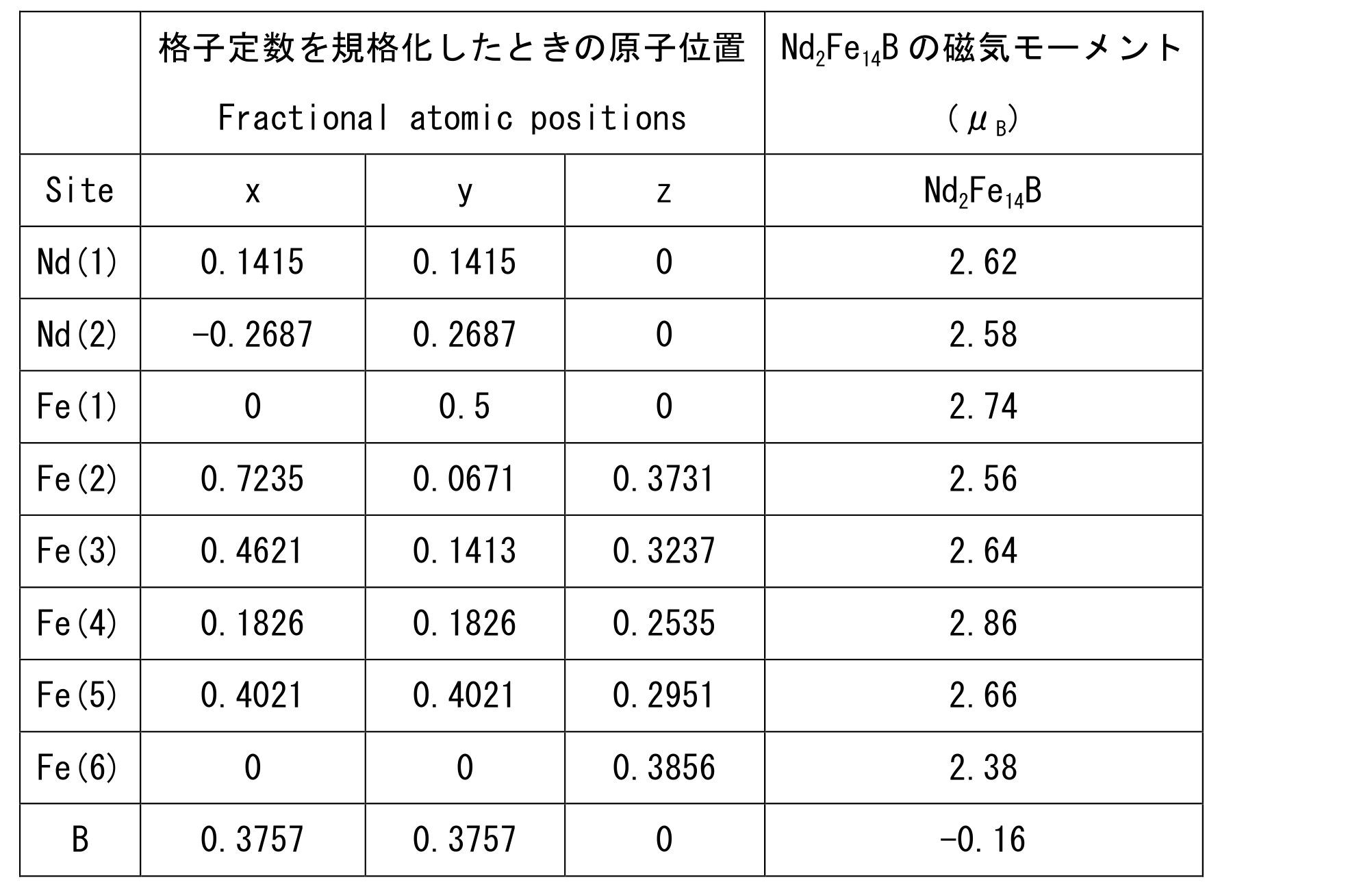
- Table 1 is a table in which magnetic moments are calculated based on atomic positions obtained by neutron diffraction (O. Isnard et. Al J. Appl. Phys. 78 (1995) 1892-1898).
- Table 1 the magnetic moment of Nd atom in Nd 2 Fe 14 B particles is less than 4 [mu] B, indicating that the magnetic moment is small.
- One cause of such a decrease in magnetic moment is that Nd atoms and B atoms are covalently bonded in the crystal structure of the particles, and some of the f electrons of Nd atoms are donated to the s orbitals of boron atoms. It is assumed that there is. As a result, it is considered that the magnetism of Nd atoms in the particles disappears.
- the present inventors have obtained knowledge that B atoms are polarized and are involved in magnetic suppression of Nd 2 Fe 14 B particles. Based on this finding, the inventors have conceived that the B atom in the crystal of the Nd 2 Fe 14 B particle is replaced with another atom to improve the magnetic property of the particle.
- the rare earth permanent magnet of the present invention has a compound represented by the following formula (1) as a main phase.
- the number of atoms of the compound in the unit cell occupies 90 to 98 at% of the number of atoms in the whole particle.
- the present invention allows the main phase to contain impurities other than the above compounds.
- M is an element selected from cobalt, beryllium, lithium, aluminum, and silicon. Further, x satisfies 0.01 ⁇ x ⁇ 0.25, and more preferably 0.03 ⁇ x ⁇ 0.25.
- the present invention has a configuration in which a part of boron in a conventional Nd 2 Fe 14 B crystal is substituted with a predetermined element. Thereby, this invention can suppress the movement to the other atom of f electron of neodymium. Therefore, the number of unpaired electrons of neodymium is easily maintained, and the magnetic moment of Nd atoms can be improved as compared with the conventional crystal.
- formula (1) when x ⁇ 0.01, the magnetic moment decreases. When x> 0.25, the crystal structure cannot be maintained and cannot be synthesized.
- a part of boron contained in the main phase is substituted with one or more atoms selected from the group consisting of cobalt, beryllium, lithium, aluminum, and silicon.
- the present invention suppresses the decrease of unpaired electrons and improves the magnetic characteristics.
- the present invention may have a configuration in which a part of boron and a part of iron in a conventional Nd 2 Fe 14 B crystal are replaced with predetermined elements.
- Such a configuration can be expressed by the following formula (2).
- M and L are elements selected from cobalt, beryllium, lithium, aluminum, and silicon
- y is 0 ⁇ y ⁇ 2
- x is 0.01 ⁇ x ⁇ 0.25, 0.01 ⁇ (x + y) ⁇ 2.25. More preferably, y is 0.1 ⁇ y ⁇ 1.2, x is 0.02 ⁇ x ⁇ 0.25, and 0.12 ⁇ (x + y) ⁇ 1.45.
- the magnetic moment of Nd atoms can be improved as compared with the above-mentioned conventional crystal.
- the magnetic moment of Fe atoms can be improved by conventionally known knowledge.
- the magnetic moment of the iron atom decreases.
- x ⁇ 0.01 or x> 0.25 the magnetic moment of neodymium atoms decreases.
- x, y, and x + y are out of the predetermined ranges, the magnetic moments of neodymium atoms and iron atoms are lowered.
- the magnetic moment of the Nd atom contained in the compound is such that the Nd atom in the Nd 2 Fe 14 B crystal has a magnetic moment. Greater than moment.
- the magnetic moment of Nd atoms present invention is greater than at least 2.70 ⁇ B, preferably 3.75 ⁇ 3.85 ⁇ B, more preferably 3.80 ⁇ 3.85 ⁇ B.
- the magnetic properties derived from Fe atoms and Nd atoms provide better magnetic properties.
- the magnetic characteristics of the present invention can be evaluated by the coercive force H cj and the residual magnetic flux density Br.
- the magnetic properties of the present invention are improved by about 40 to 50% compared to a rare earth permanent magnet made of a conventional Nd 2 Fe 14 B crystal.
- the compound constituting the main phase of the present invention contains at least one element selected from cobalt, beryllium, lithium, aluminum and silicon, neodymium, iron and boron.
- Schematic diagrams of examples of crystal structures represented by the above formulas (1) and (2) are shown in FIGS. 1 and 2, respectively.
- FIG. 1 is a schematic view showing an example of the crystal structure of the present invention represented by the formula (1).
- the compound has a basic skeleton made of Fe, and Fe layers 101 and Nd—B—M layers 102 are alternately present in the z-axis direction.
- the Nd-B-M layer 102 contains neodymium (Nd), boron (B), and the element M, and a lattice gap 103 exists.
- the element M an element whose wave function is adapted to the lattice gap 103 or an element having an atomic radius smaller than boron, for example, any element of cobalt, beryllium, lithium, aluminum, and silicon is appropriately selected.
- any one or more of cobalt, beryllium, lithium, aluminum, and silicon is preferably selected. More preferred is cobalt.
- the compound can reduce the electron donation from Nd atoms to B atoms and improve the magnetic moment of Nd atoms. .
- the present invention has a high magnetic moment and good magnetic properties.
- FIG. 2 is a schematic view showing an example of the crystal structure of the present invention represented by the formula (2).
- the compound has a basic skeleton composed of Fe atoms and L atoms, and Fe—L layers 201 and Nd—B—M layers 202 exist alternately in the z-axis direction.
- the Nd-B-M layer 202 contains neodymium (Nd), boron (B), and M atoms, and a lattice gap 203 exists.
- the iron of the above basic skeleton has a high density, it is difficult to select an element having an atomic radius excessively larger than that of the iron atom as the element L. However, if the wave functions of the elements overlap well, it is assumed that the iron atoms in the crystal are easily replaced.
- the description of the element M shown in FIG. 2 is the same as the above description of the element M shown in FIG.
- any one or more of cobalt, beryllium, lithium, aluminum, and silicon is preferably selected as the element M and the element L in the formula (2) that satisfy the above conditions. Cobalt is more preferred. Usually, the same element is selected for M and L, but different elements may be selected for M and L. From the viewpoint of simplifying the production process, it is preferable to select the same element. From the viewpoint of improving the magnetic moment of Fe atoms, it is preferable to select cobalt as at least M.
- the present invention has a high magnetic moment and good magnetic properties.
- the rare earth permanent magnet of the present invention periodically has an Nd-Fe-B layer and an Fe layer, and a part of boron contained in the Nd-Fe-B layer is cobalt, beryllium, lithium, It is substituted with one or more elements selected from the group consisting of aluminum and silicon.
- FIG. 16 is a model diagram showing the crystal structure of the main phase of the rare earth permanent magnet of the present invention, obtained as a result of analyzing the example of the present invention with the Three Dimensional Atom Probe (3DAP). Details of the embodiment and its analysis method will be described later.
- 500 is a unit cell of the main phase
- 501 is an Fe layer
- 502 is an Nd—Fe—B layer.
- FIG. 16 shows that Fe layers 501 and Nd—Fe—B layers 502 exist alternately.
- the analysis results by the Rietveld method described later indicate that cobalt atoms are present at sites where B atoms are present in the Nd—Fe—B layer in the conventional Nd 2 Fe 14 B crystal.
- the Nd-Fe-B layer preferably contains terbium.
- the Nd—Fe—B layer preferably contains one or more elements of praseodymium and dysprosium.
- An embodiment in which terbium, praseodymium, and dysprosium are present at any site of the Nd—Fe—B layer corresponds to the crystal structure of the main phase of the present invention. That is, terbium, praseodymium, and dysprosium may be substituted with Nd and Fe, respectively, or may enter the lattice gap.
- Organizing the present invention described above from the viewpoint of the main phase components it contains neodymium, iron, and boron, and further includes at least one selected from the group consisting of cobalt, beryllium, lithium, aluminum, and silicon. In other words, it can contain an element.
- the rare earth permanent magnet of the present invention contains iron as a main component more than any other component, and the iron content may be expressed as the balance with respect to the other components.
- the neodymium content is preferably 20 to 35% by weight, more preferably 22 to 33% by weight, based on the total weight of the rare earth permanent magnet.
- the boron content is preferably 0.80 to 0.99% by weight, more preferably 0.82 to 0.98% by weight.
- the total content of one or more elements selected from the group consisting of cobalt, beryllium, lithium, aluminum, and silicon is 0.8 to 1.0% by weight. Thereby, the present invention can obtain a good residual magnetic flux density Br.
- the present invention preferably contains terbium in addition to the above-described components.
- terbium in addition to any one or more elements selected from the group consisting of cobalt, beryllium, lithium, aluminum, and silicon, the present invention can improve the coercive force H cj of the rare earth permanent magnet.
- the compound containing terbium can be represented by the following formula (3) or formula (4).
- M is an element selected from cobalt, beryllium, lithium, aluminum, and silicon
- x satisfies 0.01 ⁇ x ⁇ 0.25
- z satisfies 1 ⁇ z ⁇ 1.8.
- the magnetic moment of the neodymium atom decreases.
- x> 0.25 the crystal structure becomes unstable. If z ⁇ 1, it will cause a decrease in holding power.
- z ⁇ 1.8 the residual magnetic flux density decreases.
- M and L are elements selected from cobalt, beryllium, lithium, aluminum, and silicon
- y is 0 ⁇ y ⁇ 2
- x is 0.01 ⁇ x ⁇ 0.25.
- Z is 1 ⁇ z ⁇ 1.8.
- the rare earth permanent magnet of the present invention containing terbium contains iron as a main component more than any other component, and the iron content may be expressed as the balance with respect to the other components.
- the neodymium content is preferably 20 to 35% by weight, more preferably 22 to 33% by weight, based on the total weight of the rare earth permanent magnet.
- the boron content is preferably 0.80 to 0.99% by weight, more preferably 0.82 to 0.98% by weight.
- the total content of one or more elements selected from the group consisting of cobalt, beryllium, lithium, aluminum, and silicon is 0.8 to 1.0% by weight.
- the terbium content is 2.0 to 10.0% by weight, more preferably 2.5 to 4.5% by weight. Thereby, the present invention can obtain a good residual magnetic flux density Br.
- the present invention contains neodymium, iron, and boron, and further contains any one or more elements selected from the group consisting of cobalt, beryllium, lithium, aluminum, and silicon.
- the magnetic properties satisfy at least one of the group consisting of mc1 and mc2 at °C.
- mc1 is a magnetic characteristic that the residual magnetic flux density Br is 12.90 kG or more. As mc1, it is more preferable that the residual magnetic flux density Br is 13.00 kG or more.
- mc2 is a magnetic characteristic that the coercive force H cj is 27.90 kOe or more. As mc2, the coercive force H cj is more preferably 28.20 kOe or more.
- the magnetic characteristics of the present invention can be measured using a conventionally known pulse excitation type magnetic characteristic measuring apparatus with a sample temperature variable device.
- the present invention containing the above element has magnetic properties satisfying at least one of the group consisting of mc3 and mc4 under a temperature condition of 100 ° C.
- mc3 is a magnetic characteristic that the residual magnetic flux density Br is 11.80 kG or more.
- mc3 it is more preferable that the residual magnetic flux density Br is 11.85 kG or more.
- mc4 is a magnetic characteristic that the coercive force H cj is 17.40 kOe or more.
- the coercive force H cj is more preferably 18.20 kOe or more.
- the present invention containing the above element has magnetic characteristics satisfying at least one of the group consisting of mc5 and mc6 under a temperature condition of 160 ° C.
- mc5 is a magnetic characteristic that the residual magnetic flux density Br is 10.80 kG or more.
- mc5 it is more preferable that the residual magnetic flux density Br is 10.95 kG or more.
- mc6 is a magnetic characteristic that the coercive force H cj is 10.50 kOe or more. More preferably, mc6 has a coercive force H cj of 11.00 kOe or more.
- the present invention containing the above elements has magnetic properties satisfying at least one of the group consisting of mc7 and mc8 under a temperature condition of 200 ° C.
- mc7 is a magnetic characteristic that the residual magnetic flux density Br is 10.10 kG or more.
- mc7 it is more preferable that the residual magnetic flux density Br is 10.14 kG or more.
- mc8 is a magnetic characteristic that the coercive force H cj is 6.60 kOe or more.
- the coercive force H cj is more preferably 6.90 kOe or more.
- the residual magnetic flux density Br and the coercive force H cj are both good.
- the magnetic characteristics of the present invention do not deteriorate even under temperature conditions higher than room temperature.
- the present invention may contain elements that contribute to the improvement of magnetic properties such as praseodymium and dysprosium.
- the rare earth permanent magnet of the present invention having excellent magnetic properties can be produced at low cost.
- the praseodymium contained in the present invention is mainly replaced with neodymium. It can also be dispersed in other regions within the crystal structure.
- the atomic ratio of neodymium and praseodymium contained in the present invention is 80:20 to 70:30.
- the ratio of praseodymium is large and the ratio of neodymium is small.
- the ratio of neodymium is smaller than 70 in terms of the number of atoms, the residual magnetic flux density Br is likely to be lowered.
- dysprosium By containing dysprosium, the magnetic properties can be improved in the same manner as when terbium is contained.
- the dysprosium contained in the present invention is replaced with iron.
- dysprosium As a substitution element with iron, dysprosium may be used alone or in combination with terbium. Note that terbium, praseodymium, and the like can be dispersed in other regions in the crystal structure in addition to being replaced with iron.
- a compound containing praseodymium or dysprosium can be represented by the following formula (5) or formula (6).
- M is an element selected from cobalt, beryllium, lithium, aluminum, and silicon, and x satisfies 0.01 ⁇ x ⁇ 0.25.
- R1 is praseodymium
- R2 is one or more elements of terbium and dysprosium.
- M and L are elements selected from cobalt, beryllium, lithium, aluminum, and silicon
- y is 0 ⁇ y ⁇ 2
- x is 0.01 ⁇ x ⁇ 0.25
- 0.01 ⁇ (x + y) ⁇ 2.25 is satisfied.
- z is 1 ⁇ z ⁇ 1.8.
- R1 is praseodymium
- R2 is one or more elements of terbium and dysprosium.
- the main phase of the present invention has a crystal containing neodymium, iron and boron, and containing any one or more elements selected from the group consisting of cobalt, beryllium, lithium, aluminum and silicon.
- D 50 of the sintered particle diameter of the crystal is preferably 2 to 25 ⁇ m, more preferably 3 to 15 ⁇ m, and further preferably 3 to 11 ⁇ m. In particular, when the crystal is refined to 3 to 6 ⁇ m, even if the terbium content is reduced, good magnetic properties are provided, which is preferable.
- D 50 is the median diameter in the cumulative distribution of alloy fine particles on a volume basis.
- D 50 can be measured by a known method using a laser diffraction particle size distribution measuring apparatus.
- Number representing the "powder particle size" of the present invention, "Shoyuitsubu ⁇ " and "particle size” are all D 50.
- the raw material alloy used in the present invention forms crystals as a main phase by a heat treatment process.
- D 50 of the sintering particle size of the crystal is 110 to 300% D 50 of the powder particle diameter of the raw material alloy, more particularly 110 to 180%.
- a method of forming a crystal having the sintered particle size within the above-mentioned preferable range a method of forming, magnetizing, and heat-treating a raw material alloy having an appropriate powder particle size corresponding to a desired sintered particle size Is mentioned.
- the powder particle size can be adjusted by a known method using a ball mill, a jet mill or the like.
- the sintered density is preferably 6.0 g / cm 3 or more, and more preferably 7.5 g / cm 3 or more.
- the sintered density is determined by the powder particle size of the raw material alloy, the processing temperature in the heat treatment step, the sintering temperature, and the aging temperature. Therefore, in the present invention, the sintering density is 6.0 to 8.0 g / cm 3 , more preferably 7.0 to 7.9 g / cm 3 , more preferably from the raw material alloy that can be prepared and the conditions of the heat treatment process. 7.2 to 7.7 g / cm 3 .
- the sintered density is less than 7.0 g / cm 3 , it is not suitable as a magnet.
- the present invention contains neodymium, iron and boron, further contains any one or more elements selected from the group consisting of cobalt, beryllium, lithium, aluminum and silicon, and contains terbium,
- the magnetic properties satisfy one or more of the group consisting of mc9 and mc10 at a temperature condition of 20 ° C.
- mc9 is a magnetic characteristic that the residual magnetic flux density Br is 12.50 kG or more. As mc9, it is more preferable that the residual magnetic flux density Br is 13.20 kG or more.
- mc10 is a magnetic characteristic that the coercive force H cj is 21.20 kOe or more. As mc10, the coercive force H cj is more preferably 29.50 kOe or more.
- the present invention containing the above elements has magnetic properties satisfying at least one of the group consisting of mc11 and mc12 under a temperature condition of 100 ° C.
- mc11 is a magnetic characteristic that the residual magnetic flux density Br is 11.60 kG or more.
- mc11 it is more preferable that the residual magnetic flux density Br is 12.30 kG or more.
- mc12 is a magnetic characteristic that the coercive force H cj is 11.80 kOe or more.
- the coercive force H cj is more preferably 18.00 kOe or more.
- the present invention containing the above elements has magnetic characteristics satisfying at least one of the group consisting of mc13 and mc14 under a temperature condition of 160 ° C.
- mc13 is a magnetic characteristic that the residual magnetic flux density Br is 10.60 kG or more. As mc13, it is more preferable that the residual magnetic flux density Br is 11.20 kG or more.
- mc14 is a magnetic characteristic that the coercive force H cj is 6.20 kOe or more. As mc14, the coercive force H cj is more preferably 10.00 kOe or more.
- the present invention containing the above elements has magnetic properties satisfying at least one of the group consisting of mc15 and mc16 under a temperature condition of 200 ° C.
- mc15 is a magnetic characteristic that the residual magnetic flux density Br is 9.60 kG or more.
- the residual magnetic flux density Br is more preferably 10.30 kG or more.
- mc16 is a magnetic characteristic that the coercive force H cj is 3.80 kOe or more.
- it is more preferable that the coercive force H cj is 6.00 kOe or more.
- the residual magnetic flux density Br and the coercive force H cj are both good.
- the magnetic characteristics of the present invention do not deteriorate even under temperature conditions higher than room temperature.
- the rare earth permanent magnet of the present invention containing any one or more elements selected from the group consisting of praseodymium, terbium, dysprosium, etc. contains iron as a main component more than any other component, and contains iron The amount may be expressed as the balance with respect to other ingredients.
- the neodymium content is preferably 15 to 40% by weight, more preferably 20 to 35% by weight, based on the total weight of the rare earth permanent magnet.
- the praseodymium content is 5 to 20% by weight, more preferably 5 to 15% by weight.
- the boron content is preferably 0.80 to 0.99% by weight, more preferably 0.82 to 0.98% by weight.
- the total content of one or more elements selected from the group consisting of cobalt, beryllium, lithium, aluminum, and silicon is 0.8 to 1.0% by weight.
- the content of one or more elements of terbium and dysprosium is 2.0 to 10.0% by weight, more preferably 2.5 to 4.5% by weight. Thereby, the present invention can obtain a good residual magnetic flux density Br.
- the present invention provides a grain boundary phase containing any one or more elements selected from the group consisting of aluminum, copper, niobium, zirconium, titanium, and gallium in addition to the predetermined main phase. It is preferable to provide.
- the element forming the grain boundary phase can be dispersed in the main phase as appropriate. Since the amount of dispersion is very small, it is not reflected in the preferred content of each component of the main phase.
- FIG. 6 is a schematic diagram showing an example of the microstructure of the present invention.
- 300 is the main phase and 400 is the grain boundary phase.
- the spin reversal of the main phase component is promoted by pinning the spin electrons of the main component by the spin electrons of the grain boundary phase component. . That is, the grain boundary phase breaks the magnetic exchange coupling of the main phase. As a result, the coercive force H cj can be improved.
- the preferable content of the grain boundary phase component of the present invention is 0.1 to 0.4% by weight of aluminum and 0.01 to 0.1% of copper by weight%. More preferably, aluminum is 0.2 to 0.3% and copper is 0.02 to 0.09%. When zirconium is added, the preferred content is 0.004 to 0.04%, more preferably 0.01 to 0.04%, based on the total weight of the rare earth permanent magnet in weight%.
- each component in the present invention including the main phase and the grain boundary phase contains iron as a main component more than any other content component, and the iron content is the remainder with respect to the other content components.
- the other components are from the group consisting of 20 to 35% neodymium, 0.80 to 0.99% boron, cobalt, beryllium, lithium, aluminum, and silicon in terms of% by weight based on the total weight of the present invention.
- the total amount of one or more selected elements is preferably 0.8 to 1.0%, terbium is 2.0 to 10.0%, aluminum is preferably 0.1 to 0.4%, and copper is preferably 0.01 to 0.1%.
- Examples of more preferable contents of the above-described components other than iron include at least 22 to 33% by weight of neodymium, 0.82 to 0.98% by weight, cobalt, beryllium, lithium and aluminum,
- the total amount of one or more elements selected from the group consisting of silicon is 0.8 to 1.0%, terbium is 2.6 to 5.4%, aluminum is 0.2 to 0.3%, and copper is 0.02 to 0.09% is there.
- Examples of other preferable contents are 15 to 40% by weight of neodymium, 5 to 20% by weight of praseodymium, 2.0 to 10.0% by weight of terbium, 0.80 to 0.99% by weight of boron, cobalt, beryllium and lithium.
- the total amount of one or more elements selected from the group consisting of aluminum and silicon is 0.8 to 1.0% by weight, aluminum is 0.1 to 0.4% by weight, and copper is 0.01 to 0.1% by weight in addition to the above. preferable.
- the present invention is excellent in heat resistance and combines a high residual magnetic flux density Br, a high coercive force H cj and a large maximum energy product BH max even under high temperature conditions.
- the residual magnetic flux density Br is distributed to 11.40 kG or more, preferably 12.50 kG or more, more preferably 12.90 kG or more.
- the coercive force H cj is distributed over 21.20 kOe, preferably over 27.90 kOe.
- the maximum energy product BH max is distributed to 31.00 MGOe or more, more preferably 40.10 MGOe or more.
- the residual magnetic flux density Br is distributed at least about 10.00 to 12.00 kG. In addition, it is preferably distributed over 10.60 kG, more preferably over 11.80 kG.
- the coercive force H cj is distributed to 11.80 kOe or more, and distributed from 17.00 to 19.00 kOe. Preferably, it is distributed to 17.40 kOe or more.
- the maximum energy product BH max is distributed at least from 33.00 to 35.00MGOe. In addition, it is preferably distributed over 27.10 MGOe, more preferably over 36.80 MGOe.
- the residual magnetic flux density Br is distributed at least from about 9.000 to 11.00 kG. In addition, it is preferably distributed over 9.80 kG, more preferably over 10.80 kG.
- the coercive force H cj is distributed over 6.200 kOe, and distributed between 11.00 and 12.00 kOe. Preferably, it is distributed to 10.50 kOe or more.
- the maximum energy product BH max is distributed at least about 27.00 to 29.00 MGOe. In addition, it is preferably distributed over 22.75 MGOe, more preferably over 27.80 MGOe.
- the residual magnetic flux density Br is distributed to 9.00 kG or more, preferably 9.90 to 11.00 kG, more preferably 9.60 kG or more, more preferably 10.10 kG.
- the coercive force H cj is distributed to 3.80 kOe or more, and is distributed from about 6.50 to 7.00 kOe. It is preferably distributed at 6.60 kOe or more, more preferably 15.90 kOe or more.
- the maximum energy product BH max is distributed at least about 22.90 to 24.00 MGOe. In addition, it is preferably distributed over 19.00 MGOe, more preferably over 23.70 MGOe.
- the present invention has high mechanical strength.
- the tensile strength of the rare earth permanent magnet of the present invention is 80 MPa or more, preferably 100 MPa or more, more preferably 150 MPa or more. That is, the present invention is excellent in cutting workability and can increase the mass productivity of products using the present invention. In addition, the product life can be improved.
- the tensile strength of the present invention can be measured by a method according to JIS Z2201 (tensile test piece processing method) and JIS Z2241 (tensile test measurement method).
- the method for producing the rare earth permanent magnet of the present invention is not particularly limited as long as the effects of the present invention can be obtained.
- a production method including a micronization step, a magnetization step, and a heat treatment step may be mentioned.
- the rare earth permanent magnet of the present invention can be produced by cooling the product obtained in each of the above steps to room temperature in the cooling step.
- a predetermined material such as Co and Fe, Nd, and B are dissolved in the stoichiometric ratio described above to obtain a raw material alloy.
- M, L a predetermined material such as Co and Fe, Nd, and B are dissolved in the stoichiometric ratio described above to obtain a raw material alloy.
- a starting material containing these is added as a raw material when the above-described raw material alloy is manufactured.
- the stoichiometric ratio blended in the raw material alloy is almost the same as the composition of the final product, which is the main phase compound of the present invention. Therefore, what is necessary is just to mix
- the obtained raw material alloy is roughly pulverized using a ball mill, a jet mill or the like. It is also preferable to refine the coarsely pulverized raw material alloy fine particles using a ball mill, a jet mill or the like.
- Roughly pulverized raw material alloy particles are dispersed in an organic solvent, and a reducing agent is added.
- the raw material alloy particles are made fine by the reduction treatment, and the powder particle size becomes 1.8-22.7 ⁇ m.
- the powder particle size is further reduced to 2.7 to 13.6 ⁇ m, and more specifically to 2.7 to 10.0 ⁇ m.
- the obtained raw material alloy fine particles are compression molded under an orientation magnetic field. Further, in the heat treatment step, the obtained molded body is heated under vacuum, and then the sintered product is rapidly cooled to room temperature. Subsequently, a heat treatment step is performed in an inert gas atmosphere to cool to room temperature.
- a main phase and a grain boundary phase are formed by predetermined temperature management and time management.
- the heat treatment conditions are determined based on the melting points of the contained components. That is, all the components are dissolved by raising the treatment temperature to the main phase formation temperature and holding it. Thereafter, in the process of lowering the temperature from the main phase formation temperature to the grain boundary phase formation temperature, the main phase component becomes a solid phase, and the grain boundary phase component starts to precipitate on the solid phase surface.
- a grain boundary phase can be formed by holding at the grain boundary phase formation temperature.
- heat treatment conditions for forming the main phase it is preferable to hold at 1000 to 1200 ° C. for 3 to 5 hours and then hold at 880 to 920 ° C. for 4 to 5 hours. More preferably, after holding at 1010 to 1190 ° C. for 3 to 5 hours, further holding at 890 to 910 ° C. for 3 to 5 hours.
- heat treatment conditions for forming the grain boundary phase it is preferable to hold at 480 to 520 ° C. for 3 to 5 hours, and it is preferable to hold at 490 to 510 ° C. for 3 to 5 hours.
- the present invention can be manufactured through at least the above-described steps.
- the present invention provides a known method for producing a rare earth permanent magnet only by using, as a raw material, an alloy in which Nd and Pr, Tb, and the like, Fe, B, Co, and the like are dissolved as a raw material alloy. Can be manufactured by application. Moreover, when manufacturing a rare earth permanent magnet having a predetermined main phase and a grain boundary phase, the rare earth permanent magnet of the present invention can be easily manufactured by applying the heat treatment step described above.
- the powder particle size of the raw material compound is preferably 1.8 to 22.7 ⁇ m.
- a rare earth permanent magnet having excellent magnetic properties can be produced even when the terbium content is suppressed by maintaining the main phase formation temperature more preferably at 2.7 to 13.6 ⁇ m, and even more preferably at 2.7 to 10.0 ⁇ m.
- the sintered particle size of the raw material compound becomes 110 to 300%, preferably 110 to 180% of the powder particle size.
- the sintered particle size becomes 2 to 25 ⁇ m, preferably 3 to 15 ⁇ m, more preferably 3 to 11 ⁇ m, and particularly preferably. 3-6 ⁇ m.
- the rare earth permanent magnet of the present invention whose main phase is a crystal having the above-mentioned sintered grain size reduces the terbium content by 20 to 30% and is equivalent.
- the raw material alloy particles can be obtained by pulverizing with a jet mill or pulverizing with a ball mill in order to obtain the above powder particle size.
- the alloy compound having a crystal having a preferable sintered particle size as a main phase has a sintered density of 6 to 8 g / cm 3 , more preferably 7.2 to 7.9 g / cm 3 .
- the method for measuring the sintered density is described below. The weight used in the measurement of the sintered density was measured with an electronic balance. The volume was determined by Archimedes method or by measuring the sample dimensions with a ruler.
- Cobalt (Co), Nd, Fe, and B were arc-melted to obtain a raw material alloy. 5 kg of the obtained alloy was coarsely pulverized by a ball mill to obtain alloy particles having an average particle diameter of 16 ⁇ m. Thereafter, the alloy particles were dispersed in a solvent. Additives were introduced into the dispersion and stirred to carry out a reduction reaction, whereby alloy particles were made fine. The average particle size of the obtained alloy fine powder was 16 to 25 ⁇ m.
- any one kind of metal of beryllium (Be), lithium (Li), aluminum (Al), and silicon (Si) can be similarly formed.
- a raw material compound (raw material compound 1) using cobalt (Co) was filled in a molding cavity, and compression molding and magnetization were performed by applying a molding pressure of 2 t / cm 2 and a magnetic field of 19 kOe.
- the obtained compact was heated in a 2 ⁇ 10 1 Torr Ar gas atmosphere at a treatment temperature of 1090 ° C. for 1 hour. After completion of the heat treatment, it was cooled to room temperature and taken out from the cavity, whereby the rare earth permanent magnet of Example 1 was obtained.
- the rare earth permanent magnet of Example 2-5 using any one of beryllium (Be), lithium (Li), aluminum (Al), and silicon (Si) can be obtained in the same manner.
- Example 6 to 14 A raw material alloy containing each element with the content shown in FIG. 7 was pulverized to obtain alloy particles. Thereafter, the alloy particles were dispersed in a solvent. Additives were introduced into the dispersion and stirred to carry out a reduction reaction, whereby alloy particles were made fine.
- the average particle size of Example 6 and Example 9 and the alloy fine particles was 16 to 25 ⁇ m.
- the average particle size (powder particle size) of the alloy fine particles of Example 7, Example 8, and Examples 10 to 12 was 3 to 11 ⁇ m.
- the average particle size was measured with a laser diffraction particle size distribution analyzer SALD-2300 or equivalent manufactured by Shimadzu Corporation.
- the example number means a rare earth permanent magnet having the composition of the example number shown in FIG.
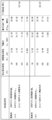
- the composition shown in FIG. 7 is the ratio of the raw material charge amount of each rare earth permanent magnet.
- the branch number of an example means the sample number of the example.
- Example 6-1, Example 6-2, and Example 6-3 are all rare earth permanent magnet samples having the composition of Example 6.
- Example 7 in addition to the charged amount shown in FIG. 7, the content in the rare earth permanent magnet was also measured.
- the measuring instrument used was an Shimadzu ICP emission spectrometer (ICP-Emission Spectroscopy) ICPS-8100 equivalent. Table 3 shows the measurement results.
- Example 6 The residual magnetic flux density Br, coercive force H cj, and maximum energy product BH max of Example 6 to Example 14 were measured.
- the tensile strength was measured at room temperature (25 ° C).
- FIGS. 8 to 10 Example 6
- FIG. 28 and FIG. 29 Example 7
- FIG. 32 and FIG. 33 Example 8
- FIG. 37 Embodiment 9
- FIGS. 40 and 41 Embodiment 10
- FIGS. 44 to 47 Embodiments 11 to 14.
- Example 6 the crystal structure of the main phase was analyzed.
- the measurement method of magnetic properties, the measurement method of tensile strength, and the analysis method of crystal structure are as follows.
- FIG. 11 is an SEM image of the needle-like object of Example 6-10.
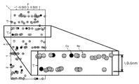
- FIG. 12 is a 3D atomic image of the needle-like material of Example 6-10.
- FIG. 13A is a 3D slice image of a needle-like object observed with 3DAP.
- FIG. 13 (B) is an enlarged view of a part of the region of FIG. 13 (A), and
- FIG. 13 (C) is an enlarged view of a part of the region of FIG. 13 (B).
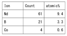
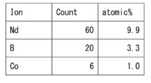
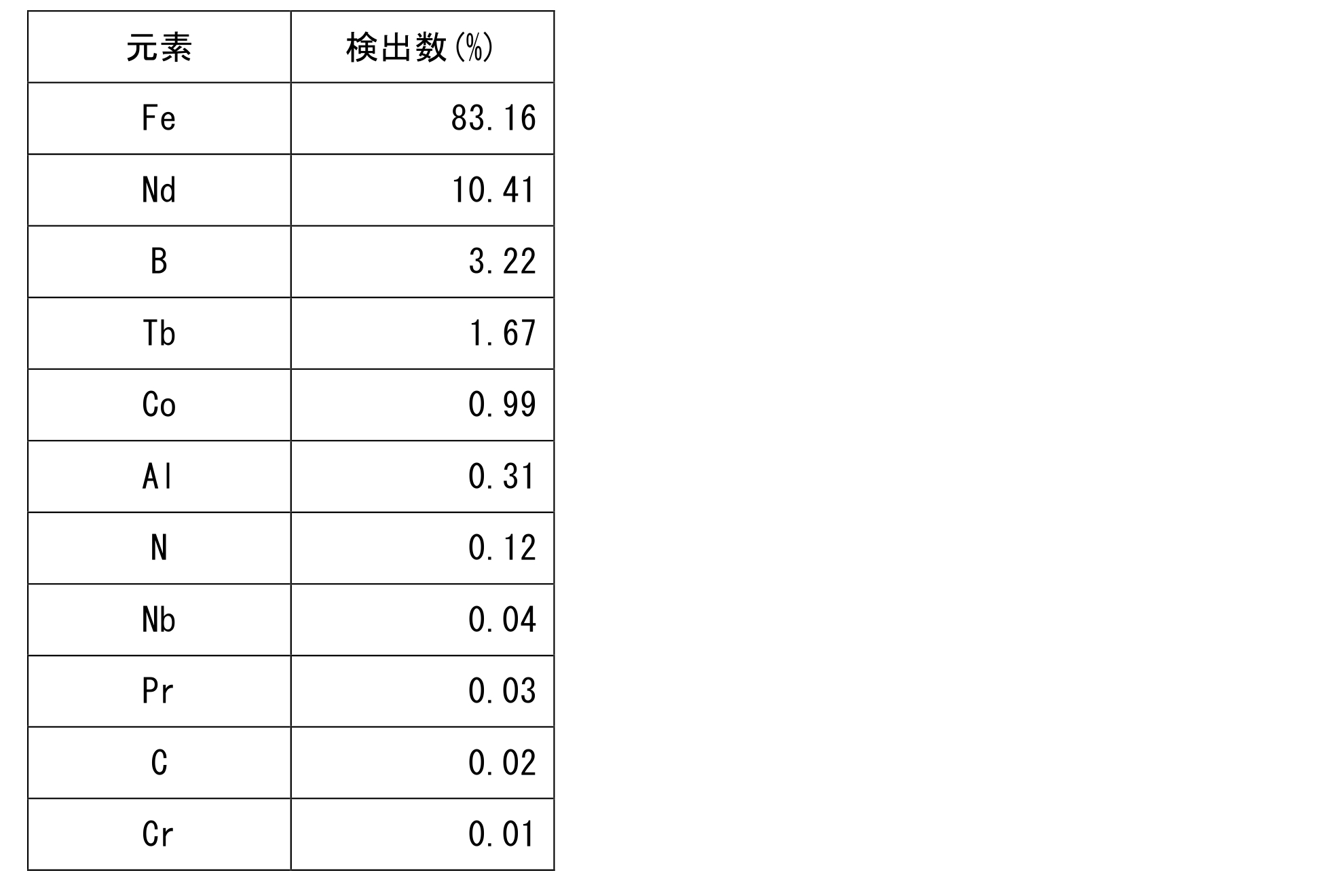
- Table 4 shows the number of detected elements detected in FIG. 13 (B).
- a lattice plane of Nd [100] was detected. The inter-surface distance was 0.59 to 0.62 nm.
- the crystal structure of the main phase of the present invention is a structure having a Nd—Fe—B layer and a Fe layer periodically.
- the Nd—Fe—B layer and the Fe layer exist alternately.
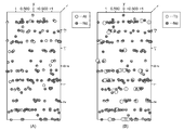
- FIG. 14 (A) shows only Nd and B displayed in the 3DAP analysis of Examples 6-10.
- FIG. 14 (B) is a diagram in which only Nd and Fe are displayed in the same analysis.
- FIG. 14C shows only Nd and Co as viewed from the x direction.
- FIG. 15 is a diagram in which only Nd and Co are displayed when viewing FIG. 14 (a) or FIG. 14 (b) from the ⁇ x direction.
- FIG. 16 is a model diagram in which the substitution atoms of the crystal structure of the main phase of the rare earth permanent magnet of the present invention are not shown, which are created based on the above 3DAP analysis.
- FIG. 17A is a diagram in which only Nd and Al are displayed in the 3DAP analysis of Examples 6-10.
- FIG. 17B is a diagram in which only Nd and Tb are displayed in the 3DAP analysis of Examples 6-10.
- FIG. 18B is a diagram in which only neodymium (Nd) is displayed in the 3DAP analysis of Examples 6-10.
- FIG. 18C shows only boron (B).
- FIG. 18D is a diagram in which only cobalt (Co) is displayed.
- FIG. 18A is a view obtained by superimposing FIGS. 18B to 18D.
- Nd-Layer 1, Nd-Layer 2, and Nd-Layer 3 shown in Fig. 18 (E) are for analyzing a layer perpendicular to the C axis of the crystal lattice of the main phase of Example 6-10 An arbitrarily selected analysis region.
- 19 and 20 are the results of 3DAP analysis of Nd-Layer IV1.
- FIG. 21 and FIG. 22 show the 3DAP analysis results of Nd-Layer 2.
- FIG. 23 and FIG. 24 show the 3DAP analysis results of Nd-Layer 3.
- 19 to 24 show that Co is present in the Nd—Fe—B layer.
- Example 6-10 indicated that Co was present in a layer parallel to the C axis of the main phase crystal lattice.
- the columnar region in the right diagram of FIG. 25 is an analysis region arbitrarily selected for analyzing a layer parallel to the C axis of the crystal lattice of the main phase of Example 6-10.
- the left diagram in FIG. 25 shows that Nd, B, and Co are detected in the direction parallel to the C axis in the analysis region shown in the right diagram in FIG.
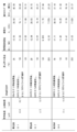
- Crystal structure analysis by Rietveld method The crystal structure of Example 6-11 was analyzed by the Rietveld method. Analysis conditions and analysis conditions are as follows.
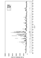
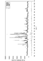
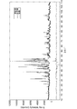
- Analysis device X-ray diffractometer RAD-RRU300 manufactured by Rigaku Corporation Target: Co Single color: Monochromator (K ⁇ ) Target output: 40kV-200mA (Continuous measurement) ⁇ / 2 ⁇ scanning slit: Divergence 1 °, Scattering 1 °, Received light 0.3mm Monochromator light receiving slit: 0.6mm Scanning speed: 0.5 ° / min Sampling width: 0.02 ° Measurement angle (2 ⁇ ): 10 ° -110 °
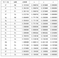
- Example 6-11 The results of analysis of the crystal structure by the Rietveld method are shown in the following figure. Specifically, the analysis results of Example 6-11 are shown in FIGS. FIG. 27 shows that the boron 4f site is substituted with 7.38% cobalt atom.
- the analysis results of Example 7-6 are shown in FIG. 30 and FIG. FIG. 31 shows that the boron 4f site is substituted with 7.40% cobalt atoms.
- the analysis results of Example 8-6 are shown in FIGS. 34 and 35.
- FIG. 35 shows that the boron 4f site is substituted with 9.87% cobalt atoms.
- the analysis results of Example 9-6 are shown in FIGS. 38 and 39.
- FIG. 39 shows that the boron 4f site is substituted with 3.64% cobalt atoms.
- the analysis results of Example 10-6 are shown in FIGS. FIG. 43 shows that the boron 4f site is substituted with 8.31% cobalt atoms.
- Example 11 The tensile strength of Example 11 was measured in Examples 11-1 to 11-5. Further, the tensile strength of Example 12 was measured in Examples 12-1 to 12-5. The measurement method is the same as in Example 6. The measurement results are shown in Table 5 IV.
- Example 13 The raw material alloys containing each element were pulverized with the contents shown in Example 13 and Example 14 of FIG. Grinding was performed with a jet mill to prepare alloy particles having different particle sizes. Thereafter, the alloy particles were dispersed in a solvent. The additive was introduced into the dispersion and stirred to carry out a reduction reaction. 45 and 46 show the particle diameters of the obtained alloy fine powder. The mixing ratio of the fine mixed powders of Example 13 and Example 14 shown in FIG. 47 is 1: 1 by weight. The powder particle size and the sintered particle size were measured with a laser diffraction particle size distribution analyzer SALD-2300 or equivalent manufactured by Shimadzu Corporation.
- 500 g of alloy fine powder of Example 13 or 500 g of alloy fine powder obtained by mixing Example 13 and Example 14 is filled into a molding cavity, and compression molding is performed by applying a molding pressure of 2 t / cm 2 and a magnetic field of 19 kOe, respectively. Magnetization was performed.
- Each obtained compact was heat-treated in a 2 ⁇ 10 1 Torr Ar atmosphere under the conditions shown in FIGS. After the heat treatment, it was cooled to room temperature. Thereafter, it was taken out from the cavity, and a rare earth permanent magnet of Example 13 and a rare earth permanent magnet of a mixed alloy of Example 13 and Example 14 were obtained.
- FIG. 48 shows the contracted state of the molded bodies of Comparative Example 1 and Comparative Example 2 after cooling. As shown in FIG. 48, the molded bodies of Comparative Example 1 and Comparative Example 2 after cooling did not contract sufficiently. Such a molded body tends to burn in subsequent processing steps. Therefore, it is assumed that the alloy fine powder having the composition of Comparative Example 1 and Comparative Example 2 does not become the magnet of the present invention.
- the rare earth permanent magnet of the present invention has a high magnetic moment and good magnetic properties. Rare earth permanent magnets contribute to miniaturization, weight reduction, and cost reduction of electric motors, offshore wind power generators, industrial motors and the like. Further, since it exhibits excellent magnetic properties even under high temperature conditions, it is suitable for automotive applications and industrial motors.
Landscapes
- Chemical & Material Sciences (AREA)
- Engineering & Computer Science (AREA)
- Mechanical Engineering (AREA)
- Organic Chemistry (AREA)
- Metallurgy (AREA)
- Materials Engineering (AREA)
- Power Engineering (AREA)
- Crystallography & Structural Chemistry (AREA)
- Manufacturing & Machinery (AREA)
- Physics & Mathematics (AREA)
- Thermal Sciences (AREA)
- Inorganic Chemistry (AREA)
- Hard Magnetic Materials (AREA)
- Powder Metallurgy (AREA)
- Manufacturing Cores, Coils, And Magnets (AREA)
- Finish Polishing, Edge Sharpening, And Grinding By Specific Grinding Devices (AREA)
Abstract
Description








本発明の希土類永久磁石の製造方法は、本発明の作用効果を得られる限り、特に制限されない。好ましい本発明の製造方法としては、微粒子化工程、着磁工程、熱処理工程とを含む製造方法が挙げられる。上記の各工程により得られた生成物を冷却工程で室温になるまで冷却させて、本発明の希土類永久磁石を製造できる。
微粒子化工程では、Co等の所定の材料(M、L)と、FeとNdとBとを上記に説明する化学量論比で溶解させ、原料合金を得る。プラセオジムや、テルビウム、アルミニウムおよび銅、ニオブ、ジルコニウム、チタン、ガリウム等を含有させる場合は、これらを含有する出発原料を、上記の原料合金製造時に原材料として添加する。
着磁工程においては、得られた原料合金微粒子を配向磁場下で圧縮成型する。さらに熱処理工程で、得られた成形体を真空下で加熱後、焼結物を室温まで急冷する。続いて不活性ガス雰囲気中で熱処理工程を行い室温まで冷却する。
熱処理工程においては、所定の温度管理と時間管理とにより主相や粒界相が形成される。熱処理条件は、含有成分の融点に基づいて決定される。すなわち処理温度を主相形成温度まで昇温させて保持することで全ての含有成分を溶解させる。その後、主相形成温度から粒界相形成温度まで温度を低下させる過程で主相成分が固相となり、粒界相成分が固相表面に析出し始める。粒界相形成温度で保持することにより粒界相を形成できる。
コバルト(Co)とNdとFeとBとをアーク溶解させ、原料合金を得た。得られた合金5kgをボールミルで粗粉砕し、平均粒径16μmの合金粒子を得た。その後合金粒子を溶媒に分散させた。分散溶液に、添加剤を導入して撹拌して還元反応を行い、合金粒子を微粒子化した。得られた合金微粉末の平均粒径は16~25μmであった。コバルト(Co)以外にも、ベリリウム(Be)、リチウム(Li)、アルミニウム(Al)、ケイ素(Si)のいずれか一種の金属についても同様にすることができる。

図7に示す含有量で各元素を含有する原料合金を粉砕し合金粒子を得た。その後合金粒子を溶媒に分散させた。分散溶液に、添加剤を導入して撹拌して還元反応を行い、合金粒子を微粒子化した。実施例6と実施例9と合金微粒子の平均粒径は、16~25μmであった。実施例7と、実施例8と、実施例10ないし実施例12との合金微粒子の平均粒径(粉末粒径)は、3~11μmであった。平均粒径は、島津製作所製レーザ回折式粒子径分布測定装置SALD-2300相当品で測定した。

測定装置:東英工業株式会社 試料温度可変装置付TPM-2-08Sパルス励磁型磁気特性測定装置相当品
JIS Z2201(引張試験片加工方法)、JIS Z2241(引張試験測定方法)に準ずる方法により行った。
実施例の希土類永久磁石の主相の結晶構造を観察するため、サンプル用に3DAP解析に用いる針状物を下記の方法により加工した。すなわち、まず実施例のサンプルは、集束イオンビーム加工観察装置(Forcused Ion Beam、FIB)にセットされた後、磁化容易方向を含む面を観察するための溝が加工された。溝を加工することで現れたサンプルの磁化容易方向を含む面に、電子線を照射した。照射により試料から放射される反射電子線をSEMで観察することで、主相(粒内)を特定した。特定された主相を、3DAPにより解析するため、針状に加工した。図11は、実施例6-10の針状物のSEM像である。
装置名 : LEAP3000XSi (AMETEK社製)
測定条件: レーザパルスモード(レーザ波長=532nm)
レーザパワー=0.5nJ、試料温度=50K
実施例6-11の結晶構造を、リートベルト法により解析した。分析条件と解析条件とは下記のとおりである。
分析装置:理学電機株式会社製X線回折装置RAD-RRU300
ターゲット:Co
単色化:モノクロメータ使用(Kα)
ターゲット出力:40kV-200mA
(連続測定)θ/2θ走査
スリット:発散1°、散乱1°、受光0.3mm
モノクロメータ受光スリット:0.6mm
走査速度:0.5°/min
サンプリング幅:0.02°
測定角度(2θ):10°-110°
リートベルト法により解析した。解析ソフトはRIETAN-FPを用い、F. Izumi and K. Momma, "Three-dimantional visualization in powder diffraction" Solid State Phenom., 130, 15-20 (2007)を参照した。座標はD.Givord, H.-S.Li and J.M.Moreau, “Magnetic properties and crystal structure of Nd2Fe14B” Solid State Communications, 50, 497-499 (1984)を採用した。

図7の実施例13と実施例14とに示す含有量で、各元素を含有する原料合金を粉砕した。粉砕はジェットミルで行い、粒径が異なる合金粒子を準備した。その後、合金粒子を溶媒に分散させた。分散溶液に、添加剤を導入して撹拌して還元反応を行った。図45と図46とに得られた合金微粉末の粒径を示す。なお図47に示す実施例13と実施例14との混合微粉末の混合比は、重量比1:1である。粉末粒径と焼結粒径とは、島津製作所製レーザ回折式粒子径分布測定装置SALD-2300相当品で測定した。
表7の比較例1と比較例2とに示す組成で各元素を含有する原料合金をそれぞれ粉砕し、平均粒径16μmの合金粒子を得た。その後合金粒子を溶媒に分散させた。分散溶液に、添加剤を導入して撹拌して還元反応を行い、合金粒子を微粒子化した。得られた合金微粉末の平均粒径は3~25μmであった。平均粒径は、島津製作所製レーザ回折式粒子径分布測定装置SALD-2300相当品で測定した。
101 Fe層
102 Nd-B-M層
103 格子間隙
200 Nd2Fe(14-y)LyB(1-x)Mxの結晶構造
201 Fe-L層
202 Nd-B-M層
203 格子間隙
300 主相
400 粒界相
500 主相の単位格子
501 Fe層
502 Nd-Fe-B層
Claims (35)
- 下記式(1)で表される化合物を主相とする希土類永久磁石。

- 前記式(1)において、xが0.03≦x≦0.25を満たす化合物を前記主相とする請求項1に記載される希土類永久磁石。
- 下記式(2)で表される化合物を主相とする希土類永久磁石。

- 前記式(2)においてyは0.1<y<1.2であり、xは0.02≦x≦0.25であり、0.12<(x+y)<1.45である化合物を前記主相とする請求項3に記載される希土類永久磁石。
- 主相がNd-Fe-B層とFe層とを周期的に有し、前記Nd-Fe-B層が含有するホウ素の一部が、コバルトと、ベリリウムと、リチウムと、アルミニウムと、ケイ素とからなる群から選択されるいずれか一種以上の元素に置換されてなる希土類永久磁石。
- 前記Nd-Fe-B層がテルビウムを含有する、請求項5に記載される希土類永久磁石。
- 前記Nd-Fe-B層がプラセオジムとジスプロシウムとのいずれか一種以上の元素を含有する、請求項5に記載される希土類永久磁石。
- ネオジムと鉄とホウ素とを含有し、コバルトと、ベリリウムと、リチウムと、アルミニウムと、ケイ素とからなる群から選択されるいずれか一種以上の元素を含有する主相を備える希土類永久磁石。
- 前記希土類永久磁石の総重量に対するネオジムの含有量が20~35重量%であり、ホウ素の含有量が0.80~0.99重量%であり、コバルトと、ベリリウムと、リチウムと、アルミニウムと、ケイ素とからなる群から選択されるいずれか一種以上の元素の含有量の合計が0.8~1.0重量%である請求項1と請求項3と請求項5と請求項8とのいずれか一項に記載される希土類永久磁石。
- テルビウムを含有する前記主相を備える請求項1と請求項3と請求項5と請求項8とのいずれか一項に記載される希土類永久磁石。
- 前記希土類永久磁石の総重量に対するネオジムの含有量が20~35重量%であり、ホウ素の含有量が0.80~0.99重量%であり、コバルトと、ベリリウムと、リチウムと、アルミニウムと、ケイ素とからなる群から選択されるいずれか一種以上の元素の含有量の合計が0.8~1.0重量%であり、テルビウムの含有量が2.0~10.0重量%である請求項1と請求項3と請求項5と請求項8とのいずれか一項に記載される希土類永久磁石。
- プラセオジムとジスプロシウムとのいずれか一種以上の元素を含有する前記主相を備える請求項1と請求項3と請求項5と請求項8と請求項10とのいずれか一項に記載される希土類永久磁石。
- 前記希土類永久磁石の総重量に対するネオジムの含有量が15~40重量%であり、プラセオジムの含有量が5~20重量%であり、ホウ素の含有量が0.80~0.99重量%であり、コバルトと、ベリリウムと、リチウムと、アルミニウムと、ケイ素とからなる群から選択されるいずれか一種以上の元素の含有量の合計が0.8~1.0重量%であり、テルビウムの含有量が2.0~10.0重量%である請求項1と請求項3と請求項5と請求項8とのいずれか一項に記載される希土類永久磁石。
- 前記主相と、アルミニウムと、銅と、ニオブと、ジルコニウムと、チタンと、ガリウムとからなる群から選択されるいずれか一種以上の元素を含有する粒界相とを備える請求項1と請求項3と請求項5と請求項8とのいずれか一項に記載される希土類永久磁石。
- 少なくとも、重量%でアルミニウムを0.1~0.4%と、銅を0.01~0.1%とを含有する粒界相を備える請求項1と請求項3と請求項5と請求項8とのいずれか一項に記載される希土類永久磁石。
- 主相が、ネオジムと鉄とホウ素とを含有し、コバルトとベリリウムとリチウムとアルミニウムと、ケイ素とからなる群から選択されるいずれか一種以上の元素を含有する結晶を有し、前記結晶の焼結粒径のD50が、2~25μmである、請求項1と請求項3と請求項5と請求項8とのいずれか一項に記載される希土類永久磁石。
- 焼結密度が、6.0~8.0g/cm3である、請求項1と請求項3と請求項5と請求項8とのいずれか一項に記載される希土類永久磁石。
- 温度条件20℃で、下記のmc1とmc2とからなる群のうち、いずれか一つ以上を満たす磁気特性を備える請求項10に記載される希土類永久磁石。
mc1:残留磁束密度Brが12.90kG以上である。
mc2:保磁力Hcjが27.90kOe以上である。 - 温度条件100℃で、下記のmc3とmc4とからなる群のうち、いずれか一つ以上を満たす磁気特性を備える請求項10に記載される希土類永久磁石。
mc3:残留磁束密度Brが11.80kG以上である。
mc4:保磁力Hcjが17.40kOe以上である。 - 温度条件160℃で、下記のmc5とmc6とからなる群のうち、いずれか一つ以上を満たす磁気特性を備える請求項10に記載される希土類永久磁石。
mc5:残留磁束密度Brが10.80kG以上である。
mc6:保磁力Hcjが10.50kOe以上である。 - 温度条件200℃で、下記のmc7とmc8とからなる群のうち、いずれか一つ以上を満たす磁気特性を備える請求項10に記載される希土類永久磁石。
mc7:残留磁束密度Brが10.10kG以上である。
mc8:保磁力Hcjが6.60kOe以上である。 - 温度条件20℃で、下記のmc9とmc10とからなる群のうち、いずれか一つ以上を満たす磁気特性を備える請求項12に記載される希土類永久磁石。
mc9:残留磁束密度Brが12.50kG以上である。
mc10:保磁力Hcjが21.20kOe以上である。 - 温度条件100℃で、下記のmc11とmc12とからなる群のうち、いずれか一つ以上を満たす磁気特性を備える請求項12に記載される希土類永久磁石。
mc11:残留磁束密度Brが11.60kG以上である。
mc12:保磁力Hcjが11.80kOe以上である。 - 温度条件160℃で、下記のmc13とmc14とからなる群のうち、いずれか一つ以上を満たす磁気特性を備える請求項12に記載される希土類永久磁石。
mc13:残留磁束密度Brが10.60kG以上である。
mc14:保磁力Hcjが6.20kOe以上である。 - 温度条件200℃で、下記のmc15とmc16とからなる群のうち、いずれか一つ以上を満たす磁気特性を備える請求項12に記載される希土類永久磁石。
mc15:残留磁束密度Brが9.60kG以上である。
mc16:保磁力Hcjが3.80kOe以上である。 - 温度条件20℃で、下記のmc17とmc18とからなる群のうち、いずれか一つ以上を満たす磁気特性を備える請求項14に記載される希土類永久磁石。
mc17:残留磁束密度Brが11.40kG以上である。
mc18:保磁力Hcjが28.00kOe以上である。 - 温度条件100℃で、下記のmc19とmc20とからなる群のうち、いずれか一つ以上を満たす磁気特性を備える請求項14に記載される希土類永久磁石。
mc19:残留磁束密度Brが10.60kG以上である。
mc20:保磁力Hcjが17.70kOe以上である。 - 温度条件160℃で、下記のmc21とmc22とからなる群のうち、いずれか一つ以上を満たす磁気特性を備える請求項14に記載される希土類永久磁石。
mc21:残留磁束密度Brが9.80kG以上である。
mc22:保磁力Hcjが10.60kOe以上である。 - 温度条件200℃で、下記のmc23とmc24とからなる群のうち、いずれか一つ以上を満たす磁気特性を備える請求項14に記載される希土類永久磁石。
mc23:残留磁束密度Brが9.00kG以上である。
mc24:保磁力Hcjが6.70kOe以上である。 - 引張強度が80MPa以上である請求項1と請求項3と請求項5と請求項8とのいずれか一項に記載される希土類永久磁石。
- 引張強度が100MPa以上である請求項1と請求項3と請求項5と請求項8とのいずれか一項に記載される希土類永久磁石。
- 引張強度が150MPa以上である請求項1と請求項3と請求項5と請求項8とのいずれか一項に記載される希土類永久磁石。
- ネオジムと鉄とホウ素とを含有し、コバルトと、ベリリウムと、リチウムと、アルミニウムと、ケイ素とからなる群から選択されるいずれか一種以上の元素と、テルビウムとを含有し、アルミニウムと、銅と、ニオブと、ジルコニウムと、チタンと、ガリウムとからなる群から選択されるいずれか一種以上の元素とを含有する原料化合物を、主相形成温度で保持した後、粒界相形成温度まで低下させて、ネオジムと鉄とホウ素とを含有し、コバルトと、ベリリウムと、リチウムと、アルミニウムと、ケイ素とからなる群から選択されるいずれか一種以上の元素と、テルビウムとを含有する主相を形成し、さらに前記粒界相形成温度で保持して、アルミニウムと、銅と、ニオブと、ジルコニウムと、チタンと、ガリウムとからなる群から選択される一種以上の元素を含有する粒界相を形成する熱処理工程を含む、希土類永久磁石の製造方法。
- ネオジムとプラセオジムと鉄とホウ素とを含有し、コバルトと、ベリリウムと、リチウムと、アルミニウムと、ケイ素とからなる群から選択されるいずれか一種以上の元素と、テルビウムと、ジスプロシウムとのいずれか一種以上の元素とを含有し、アルミニウムと、銅と、ニオブと、ジルコニウムと、チタンと、ガリウムとからなる群から選択されるいずれか一種以上の元素とを含有する原料化合物を、前記主相形成温度で保持した後、前記粒界相形成温度まで低下させて、ネオジムとプラセオジムと鉄とホウ素とを含有し、さらにコバルトと、ベリリウムと、リチウムと、アルミニウムと、ケイ素からなる群から選択されるいずれか一種以上の元素と、テルビウムと、ジスプロシウムとのいずれか一種以上の元素とを含有する前記主相を形成し、前記粒界相形成温度で保持して、アルミニウムと、銅と、ニオブと、ジルコニウムと、チタンと、ガリウムとからなる群から選択される一種以上の元素を含有する前記粒界相を形成する前記熱処理工程を含む、請求項33に記載される希土類永久磁石の製造方法。
- 1000~1200℃で3~5時間保持した後、880~920℃で4~5時間保持し、その後480~520℃で3~5時間保持する前記熱処理工程を含む請求項33または請求項34に記載される希土類永久磁石の製造方法。
Priority Applications (6)
| Application Number | Priority Date | Filing Date | Title |
|---|---|---|---|
| KR1020167011619A KR101936174B1 (ko) | 2013-11-05 | 2014-11-04 | 희토류 영구자석 및 희토류 영구자석의 제조 방법 |
| JP2015546639A JP6451643B2 (ja) | 2013-11-05 | 2014-11-04 | 希土類永久磁石および希土類永久磁石の製造方法 |
| AU2014344917A AU2014344917B2 (en) | 2013-11-05 | 2014-11-04 | Rare earth permanent magnet and method for manufacturing rare earth permanent magnet |
| EP14860236.0A EP3067900B1 (en) | 2013-11-05 | 2014-11-04 | Rare earth permanent magnet and method for manufacturing rare earth permanent magnet |
| CN201480060710.1A CN105706190B (zh) | 2013-11-05 | 2014-11-04 | 稀土永磁材料以及稀土永磁材料的制造方法 |
| US15/146,932 US10629343B2 (en) | 2013-11-05 | 2016-05-05 | Rare earth permanent magnet and rare earth permanent magnet manufacturing method |
Applications Claiming Priority (10)
| Application Number | Priority Date | Filing Date | Title |
|---|---|---|---|
| JP2013-229783 | 2013-11-05 | ||
| JP2013229783 | 2013-11-05 | ||
| JP2013-229786 | 2013-11-05 | ||
| JP2013229786 | 2013-11-05 | ||
| JP2014-002051 | 2014-01-08 | ||
| JP2014002051 | 2014-01-08 | ||
| JP2014-002050 | 2014-01-08 | ||
| JP2014002050 | 2014-01-08 | ||
| JP2014110669 | 2014-05-28 | ||
| JP2014-110669 | 2014-05-28 |
Related Child Applications (1)
| Application Number | Title | Priority Date | Filing Date |
|---|---|---|---|
| US15/146,932 Continuation US10629343B2 (en) | 2013-11-05 | 2016-05-05 | Rare earth permanent magnet and rare earth permanent magnet manufacturing method |
Publications (1)
| Publication Number | Publication Date |
|---|---|
| WO2015068681A1 true WO2015068681A1 (ja) | 2015-05-14 |
Family
ID=53041458
Family Applications (1)
| Application Number | Title | Priority Date | Filing Date |
|---|---|---|---|
| PCT/JP2014/079183 Ceased WO2015068681A1 (ja) | 2013-11-05 | 2014-11-04 | 希土類永久磁石および希土類永久磁石の製造方法 |
Country Status (7)
| Country | Link |
|---|---|
| US (1) | US10629343B2 (ja) |
| EP (1) | EP3067900B1 (ja) |
| JP (1) | JP6451643B2 (ja) |
| KR (1) | KR101936174B1 (ja) |
| CN (2) | CN109887697B (ja) |
| AU (1) | AU2014344917B2 (ja) |
| WO (1) | WO2015068681A1 (ja) |
Cited By (5)
| Publication number | Priority date | Publication date | Assignee | Title |
|---|---|---|---|---|
| JP2016040791A (ja) * | 2014-08-12 | 2016-03-24 | Tdk株式会社 | 永久磁石 |
| JP2018074003A (ja) * | 2016-10-28 | 2018-05-10 | 株式会社Ihi | 希土類永久磁石および希土類永久磁石の製造方法 |
| JP2018074004A (ja) * | 2016-10-28 | 2018-05-10 | 株式会社Ihi | 希土類永久磁石および希土類永久磁石の製造方法 |
| JP2019174298A (ja) * | 2018-03-28 | 2019-10-10 | 住友金属鉱山株式会社 | 組成判定方法、組成判定装置 |
| US11473175B2 (en) | 2017-11-28 | 2022-10-18 | Lg Chem, Ltd. | Method for producing magnetic powder and magnetic powder |
Families Citing this family (9)
| Publication number | Priority date | Publication date | Assignee | Title |
|---|---|---|---|---|
| AU2016253743B2 (en) * | 2015-04-30 | 2018-12-20 | Ihi Corporation | Rare earth permanent magnet and method for producing rare earth permanent magnet |
| CN106673148B (zh) * | 2017-01-19 | 2019-03-29 | 万明蓉 | 一种高效磁化器 |
| CN106920614B (zh) * | 2017-03-02 | 2019-01-18 | 沈阳寰博磁电科技有限公司 | 一种高磁性因子烧结钕铁硼的制备方法 |
| KR102187561B1 (ko) | 2019-10-25 | 2020-12-07 | 한국생산기술연구원 | Ti이 첨가된 Nd-Fe-B계 영구자석 제조 방법 |
| EP3842555B1 (en) * | 2019-12-26 | 2024-02-14 | Proterial, Ltd. | Soft magnetic alloy and magnetic core |
| KR102333257B1 (ko) * | 2020-10-16 | 2021-12-01 | 한양대학교 에리카산학협력단 | 자성 분말의 제조 방법 |
| KR20230170312A (ko) | 2022-06-10 | 2023-12-19 | 문수민 | 음식물쓰레기 수분 흡수 패드 |
| CN116453604A (zh) * | 2023-03-17 | 2023-07-18 | 西南科技大学 | 提高钐钴SmCo5永磁体晶面磁性性能的模拟方法 |
| CN120299895B (zh) * | 2025-06-11 | 2025-08-15 | 国瑞科创稀土功能材料(赣州)有限公司 | 一种R-Fe-B系永磁材料及其制备方法 |
Citations (11)
| Publication number | Priority date | Publication date | Assignee | Title |
|---|---|---|---|---|
| US5645651A (en) | 1982-08-21 | 1997-07-08 | Sumitomo Special Metals Co., Ltd. | Magnetic materials and permanent magnets |
| JPH118109A (ja) * | 1997-04-21 | 1999-01-12 | Shin Etsu Chem Co Ltd | 希土類永久磁石材料及びその製造方法 |
| JP2002038245A (ja) * | 2000-07-27 | 2002-02-06 | Hitachi Metals Ltd | 希土類永久磁石用合金粉末および希土類永久磁石の製造方法 |
| JP2002327255A (ja) * | 2001-03-01 | 2002-11-15 | Tdk Corp | 焼結磁石 |
| JP2003217918A (ja) | 2002-01-25 | 2003-07-31 | Hitachi Metals Ltd | 着磁性に優れた希土類焼結磁石用合金粉末、希土類焼結磁石およびその製造方法 |
| JP2003226944A (ja) * | 2002-02-05 | 2003-08-15 | Sumitomo Special Metals Co Ltd | 希土類−鉄−硼素系磁石用合金粉末を用いた焼結磁石 |
| JP2005320628A (ja) * | 2004-04-07 | 2005-11-17 | Showa Denko Kk | R−t−b系焼結磁石用合金塊、その製造法および磁石 |
| JP2008505500A (ja) | 2004-06-30 | 2008-02-21 | ユニバーシティ・オブ・デイトン | 異方性ナノコンポジット希土類永久磁石とそれらの製造方法 |
| JP2008117855A (ja) | 2006-11-01 | 2008-05-22 | Toyota Motor Corp | ナノコンポジット磁石の製造方法 |
| JP2010074062A (ja) | 2008-09-22 | 2010-04-02 | Toyota Motor Corp | NdFeB/FeCoナノコンポジット磁石 |
| JP2010150604A (ja) * | 2008-12-25 | 2010-07-08 | Tdk Corp | 希土類焼結磁石の製造方法 |
Family Cites Families (13)
| Publication number | Priority date | Publication date | Assignee | Title |
|---|---|---|---|---|
| CA1271394A (en) * | 1985-02-25 | 1990-07-10 | Karen S. Canavan | Enhanced remanence permanent magnetic alloy and bodies thereof and method of preparing same |
| US5641363A (en) * | 1993-12-27 | 1997-06-24 | Tdk Corporation | Sintered magnet and method for making |
| US5976271A (en) | 1997-04-21 | 1999-11-02 | Shin-Etsu Chemical Co., Ltd. | Method for the preparation of rare earth based anisotropic permanent magnet |
| JP2001217112A (ja) * | 2000-01-31 | 2001-08-10 | Hitachi Metals Ltd | R−t−b系焼結磁石 |
| JP2006041507A (ja) | 2001-03-01 | 2006-02-09 | Tdk Corp | 焼結磁石 |
| US7199690B2 (en) * | 2003-03-27 | 2007-04-03 | Tdk Corporation | R-T-B system rare earth permanent magnet |
| EP1738377B1 (en) * | 2004-04-07 | 2012-10-03 | Showa Denko K.K. | Alloy lump for r-t-b type sintered magnet, producing method thereof, and magnet |
| KR101456841B1 (ko) * | 2006-09-14 | 2014-11-03 | 가부시키가이샤 알박 | 영구자석 및 영구자석의 제조방법 |
| JP5115511B2 (ja) * | 2008-03-28 | 2013-01-09 | Tdk株式会社 | 希土類磁石 |
| CN101582317B (zh) * | 2008-05-15 | 2012-09-19 | 三环瓦克华(北京)磁性器件有限公司 | 新型烧结钕铁硼稀土永磁材料及其制造方法 |
| JP2010263172A (ja) * | 2008-07-04 | 2010-11-18 | Daido Steel Co Ltd | 希土類磁石およびその製造方法 |
| CN101451215A (zh) * | 2009-01-04 | 2009-06-10 | 上海大学 | 一种纳米晶复合NdFeB永磁合金及其制备方法 |
| CN103875045B (zh) | 2011-10-13 | 2016-08-31 | Tdk株式会社 | R-t-b 系合金薄片、r-t-b 系烧结磁体及其制造方法 |
-
2014
- 2014-11-04 CN CN201910313530.4A patent/CN109887697B/zh active Active
- 2014-11-04 CN CN201480060710.1A patent/CN105706190B/zh active Active
- 2014-11-04 KR KR1020167011619A patent/KR101936174B1/ko not_active Expired - Fee Related
- 2014-11-04 WO PCT/JP2014/079183 patent/WO2015068681A1/ja not_active Ceased
- 2014-11-04 JP JP2015546639A patent/JP6451643B2/ja active Active
- 2014-11-04 AU AU2014344917A patent/AU2014344917B2/en active Active
- 2014-11-04 EP EP14860236.0A patent/EP3067900B1/en active Active
-
2016
- 2016-05-05 US US15/146,932 patent/US10629343B2/en active Active
Patent Citations (11)
| Publication number | Priority date | Publication date | Assignee | Title |
|---|---|---|---|---|
| US5645651A (en) | 1982-08-21 | 1997-07-08 | Sumitomo Special Metals Co., Ltd. | Magnetic materials and permanent magnets |
| JPH118109A (ja) * | 1997-04-21 | 1999-01-12 | Shin Etsu Chem Co Ltd | 希土類永久磁石材料及びその製造方法 |
| JP2002038245A (ja) * | 2000-07-27 | 2002-02-06 | Hitachi Metals Ltd | 希土類永久磁石用合金粉末および希土類永久磁石の製造方法 |
| JP2002327255A (ja) * | 2001-03-01 | 2002-11-15 | Tdk Corp | 焼結磁石 |
| JP2003217918A (ja) | 2002-01-25 | 2003-07-31 | Hitachi Metals Ltd | 着磁性に優れた希土類焼結磁石用合金粉末、希土類焼結磁石およびその製造方法 |
| JP2003226944A (ja) * | 2002-02-05 | 2003-08-15 | Sumitomo Special Metals Co Ltd | 希土類−鉄−硼素系磁石用合金粉末を用いた焼結磁石 |
| JP2005320628A (ja) * | 2004-04-07 | 2005-11-17 | Showa Denko Kk | R−t−b系焼結磁石用合金塊、その製造法および磁石 |
| JP2008505500A (ja) | 2004-06-30 | 2008-02-21 | ユニバーシティ・オブ・デイトン | 異方性ナノコンポジット希土類永久磁石とそれらの製造方法 |
| JP2008117855A (ja) | 2006-11-01 | 2008-05-22 | Toyota Motor Corp | ナノコンポジット磁石の製造方法 |
| JP2010074062A (ja) | 2008-09-22 | 2010-04-02 | Toyota Motor Corp | NdFeB/FeCoナノコンポジット磁石 |
| JP2010150604A (ja) * | 2008-12-25 | 2010-07-08 | Tdk Corp | 希土類焼結磁石の製造方法 |
Non-Patent Citations (6)
| Title |
|---|
| D.GIVORD; H.-S.LI; J.M.MOREAU: "Magnetic properties and crystal structure of NdsFeuB", SOLID STATE COMMUNICATIONS, vol. 50, 1984, pages 497 - 499, XP024541708, DOI: doi:10.1016/0038-1098(84)90315-6 |
| F. IZUMI; K. MOMMA: "Three-dimensional visualization in powder diffraction", SOLID STATE PHENOM., vol. 130, 2007, pages 15 - 20 |
| G. S. CHAUBEY; J. P. LIU ET AL., J. AM. CHEM. SOC., vol. 129, 2007, pages 7214 |
| O. ISNARD, J.APPL. PHYS., vol. 78, 1995, pages 1892 - 1898 |
| O.LSNARD, J.APPL. PHYS., vol. 78, 1995, pages 1892 - 1898 |
| See also references of EP3067900A4 |
Cited By (6)
| Publication number | Priority date | Publication date | Assignee | Title |
|---|---|---|---|---|
| JP2016040791A (ja) * | 2014-08-12 | 2016-03-24 | Tdk株式会社 | 永久磁石 |
| JP2018074003A (ja) * | 2016-10-28 | 2018-05-10 | 株式会社Ihi | 希土類永久磁石および希土類永久磁石の製造方法 |
| JP2018074004A (ja) * | 2016-10-28 | 2018-05-10 | 株式会社Ihi | 希土類永久磁石および希土類永久磁石の製造方法 |
| US11473175B2 (en) | 2017-11-28 | 2022-10-18 | Lg Chem, Ltd. | Method for producing magnetic powder and magnetic powder |
| JP2019174298A (ja) * | 2018-03-28 | 2019-10-10 | 住友金属鉱山株式会社 | 組成判定方法、組成判定装置 |
| JP7073842B2 (ja) | 2018-03-28 | 2022-05-24 | 住友金属鉱山株式会社 | 組成判定方法、組成判定装置 |
Also Published As
| Publication number | Publication date |
|---|---|
| CN105706190B (zh) | 2019-05-10 |
| US20160322135A1 (en) | 2016-11-03 |
| AU2014344917A1 (en) | 2016-05-26 |
| KR101936174B1 (ko) | 2019-01-08 |
| AU2014344917B2 (en) | 2018-03-22 |
| EP3067900A4 (en) | 2017-08-02 |
| CN105706190A (zh) | 2016-06-22 |
| US10629343B2 (en) | 2020-04-21 |
| KR20160078979A (ko) | 2016-07-05 |
| CN109887697B (zh) | 2021-07-20 |
| EP3067900A1 (en) | 2016-09-14 |
| CN109887697A (zh) | 2019-06-14 |
| EP3067900B1 (en) | 2020-06-10 |
| JP6451643B2 (ja) | 2019-01-16 |
| JPWO2015068681A1 (ja) | 2017-03-09 |
Similar Documents
| Publication | Publication Date | Title |
|---|---|---|
| JP6451643B2 (ja) | 希土類永久磁石および希土類永久磁石の製造方法 | |
| CN104078176B (zh) | 稀土类磁体 | |
| JP6144359B2 (ja) | NdFeB系焼結磁石及びその製造方法 | |
| WO2015129861A1 (ja) | R-t-b系焼結磁石およびその製造方法 | |
| JP6142792B2 (ja) | 希土類磁石 | |
| JP2020123735A (ja) | 希土類磁石 | |
| JP6142793B2 (ja) | 希土類磁石 | |
| JP6332479B2 (ja) | 希土類永久磁石および希土類永久磁石の製造方法 | |
| JP6728860B2 (ja) | 希土類磁石 | |
| JP6507769B2 (ja) | R−t−b系焼結磁石 | |
| JP2015038951A (ja) | 希土類磁石 | |
| JP6614365B2 (ja) | 希土類−遷移金属系強磁性合金 | |
| CN110024056B (zh) | 稀土类烧结磁铁 | |
| JP6519300B2 (ja) | 希土類永久磁石および希土類永久磁石の製造方法 | |
| JP2014209547A (ja) | 希土類磁石 | |
| Zhong | Synthesis of Nd-Fe-B based magnetic materials through the mechanochemical process |
Legal Events
| Date | Code | Title | Description |
|---|---|---|---|
| 121 | Ep: the epo has been informed by wipo that ep was designated in this application |
Ref document number: 14860236 Country of ref document: EP Kind code of ref document: A1 |
|
| ENP | Entry into the national phase |
Ref document number: 2015546639 Country of ref document: JP Kind code of ref document: A |
|
| ENP | Entry into the national phase |
Ref document number: 20167011619 Country of ref document: KR Kind code of ref document: A |
|
| REEP | Request for entry into the european phase |
Ref document number: 2014860236 Country of ref document: EP |
|
| WWE | Wipo information: entry into national phase |
Ref document number: 2014860236 Country of ref document: EP |
|
| NENP | Non-entry into the national phase |
Ref country code: DE |
|
| ENP | Entry into the national phase |
Ref document number: 2014344917 Country of ref document: AU Date of ref document: 20141104 Kind code of ref document: A |