WO2015068737A1 - 軸受状態検知装置及び軸受状態検知方法 - Google Patents
軸受状態検知装置及び軸受状態検知方法 Download PDFInfo
- Publication number
- WO2015068737A1 WO2015068737A1 PCT/JP2014/079360 JP2014079360W WO2015068737A1 WO 2015068737 A1 WO2015068737 A1 WO 2015068737A1 JP 2014079360 W JP2014079360 W JP 2014079360W WO 2015068737 A1 WO2015068737 A1 WO 2015068737A1
- Authority
- WO
- WIPO (PCT)
- Prior art keywords
- bearing
- state
- state detection
- damage
- railway vehicle
- Prior art date
- Legal status (The legal status is an assumption and is not a legal conclusion. Google has not performed a legal analysis and makes no representation as to the accuracy of the status listed.)
- Ceased
Links
Images


Classifications
-
- G—PHYSICS
- G01—MEASURING; TESTING
- G01M—TESTING STATIC OR DYNAMIC BALANCE OF MACHINES OR STRUCTURES; TESTING OF STRUCTURES OR APPARATUS, NOT OTHERWISE PROVIDED FOR
- G01M13/00—Testing of machine parts
- G01M13/04—Bearings
- G01M13/045—Acoustic or vibration analysis
-
- B—PERFORMING OPERATIONS; TRANSPORTING
- B61—RAILWAYS
- B61C—LOCOMOTIVES; MOTOR RAILCARS
- B61C9/00—Locomotives or motor railcars characterised by the type of transmission system used; Transmission systems specially adapted for locomotives or motor railcars
- B61C9/38—Transmission systems in or for locomotives or motor railcars with electric motor propulsion
- B61C9/48—Transmission systems in or for locomotives or motor railcars with electric motor propulsion with motors supported on vehicle frames and driving axles, e.g. axle or nose suspension
-
- B—PERFORMING OPERATIONS; TRANSPORTING
- B61—RAILWAYS
- B61K—AUXILIARY EQUIPMENT SPECIALLY ADAPTED FOR RAILWAYS, NOT OTHERWISE PROVIDED FOR
- B61K9/00—Railway vehicle profile gauges; Detecting or indicating overheating of components; Apparatus on locomotives or cars to indicate bad track sections; General design of track recording vehicles
-
- F—MECHANICAL ENGINEERING; LIGHTING; HEATING; WEAPONS; BLASTING
- F16—ENGINEERING ELEMENTS AND UNITS; GENERAL MEASURES FOR PRODUCING AND MAINTAINING EFFECTIVE FUNCTIONING OF MACHINES OR INSTALLATIONS; THERMAL INSULATION IN GENERAL
- F16C—SHAFTS; FLEXIBLE SHAFTS; ELEMENTS OR CRANKSHAFT MECHANISMS; ROTARY BODIES OTHER THAN GEARING ELEMENTS; BEARINGS
- F16C19/00—Bearings with rolling contact, for exclusively rotary movement
- F16C19/52—Bearings with rolling contact, for exclusively rotary movement with devices affected by abnormal or undesired conditions
-
- G—PHYSICS
- G01—MEASURING; TESTING
- G01M—TESTING STATIC OR DYNAMIC BALANCE OF MACHINES OR STRUCTURES; TESTING OF STRUCTURES OR APPARATUS, NOT OTHERWISE PROVIDED FOR
- G01M13/00—Testing of machine parts
- G01M13/04—Bearings
-
- G—PHYSICS
- G01—MEASURING; TESTING
- G01M—TESTING STATIC OR DYNAMIC BALANCE OF MACHINES OR STRUCTURES; TESTING OF STRUCTURES OR APPARATUS, NOT OTHERWISE PROVIDED FOR
- G01M17/00—Testing of vehicles
- G01M17/08—Railway vehicles
- G01M17/10—Suspensions, axles or wheels
-
- F—MECHANICAL ENGINEERING; LIGHTING; HEATING; WEAPONS; BLASTING
- F16—ENGINEERING ELEMENTS AND UNITS; GENERAL MEASURES FOR PRODUCING AND MAINTAINING EFFECTIVE FUNCTIONING OF MACHINES OR INSTALLATIONS; THERMAL INSULATION IN GENERAL
- F16C—SHAFTS; FLEXIBLE SHAFTS; ELEMENTS OR CRANKSHAFT MECHANISMS; ROTARY BODIES OTHER THAN GEARING ELEMENTS; BEARINGS
- F16C2326/00—Articles relating to transporting
- F16C2326/10—Railway vehicles
-
- Y—GENERAL TAGGING OF NEW TECHNOLOGICAL DEVELOPMENTS; GENERAL TAGGING OF CROSS-SECTIONAL TECHNOLOGIES SPANNING OVER SEVERAL SECTIONS OF THE IPC; TECHNICAL SUBJECTS COVERED BY FORMER USPC CROSS-REFERENCE ART COLLECTIONS [XRACs] AND DIGESTS
- Y02—TECHNOLOGIES OR APPLICATIONS FOR MITIGATION OR ADAPTATION AGAINST CLIMATE CHANGE
- Y02T—CLIMATE CHANGE MITIGATION TECHNOLOGIES RELATED TO TRANSPORTATION
- Y02T30/00—Transportation of goods or passengers via railways, e.g. energy recovery or reducing air resistance
Definitions
- the present invention relates to a bearing state detecting device and a bearing state detecting method for detecting the state of a bearing of a gear device constituting a carriage of a railway vehicle.
- the rotating device for detecting vibrations of a bearing abnormality of a railway vehicle carriage disclosed in Patent Document 1 is a non-disassembled and accurate accuracy of a bearing abnormality such as a journal bearing or a gear reducer attached to a wheel shaft of a railway vehicle carriage. It is a device for detection. In the vibration inspection using the device, the vibration of the bearing is measured by rotating the wheel shaft under a load condition close to actual driving and detecting the damage vibration generated by the roller in the journal bearing or gear reduction device with the vibration measurement sensor. I do.
- the apparatus described in Patent Document 1 described above detects damage vibration by rotating a wheel shaft of a railway vehicle carriage under a load condition close to actual traveling.
- the railway vehicle is traveling under a load that cannot be reproduced by the apparatus of Patent Document 1. That is, the load that the railway vehicle receives during actual traveling includes various parameters including environmental factors such as wind and temperature and factors due to track conditions. Therefore, in the apparatus of Patent Document 1, although the wheel shaft is rotated under a load condition close to actual traveling, damage vibration based on the load actually received by the bearing during actual traveling is not detected. The actual condition of the bearing may not be detected depending on the damaged part or the degree of damage.
- An object of the present invention is to provide a bearing state detection device and a bearing state detection method capable of detecting with high accuracy the actual condition relating to the damage of the bearing of the gear device constituting the bogie of the railway vehicle.
- a bearing state detection device that detects a state of a bearing of a gear device that constitutes a bogie of a railway vehicle
- a bearing state detection device that detects an actual state of damage to the bearing based on information including a parameter related to the state of the bearing, which is measured when the railway vehicle is actually running.
- the actual condition analysis unit compares the result of analyzing the information processed by the filtering processing unit with the result of analyzing the information processed by the filtering processing unit when the bearing is in a normal state.
- the information including the parameter relating to the state of the bearing is a measured value of a sensor installed in the vicinity of the bearing of the gear device, according to any one of (1) to (3), Bearing state detection device.
- the information including the parameter relating to the state of the bearing is at least one of vibration, temperature, torque, displacement, AE (Acoustic Emission), and rotational speed (1) to ( 4)
- the bearing state detection apparatus in any one of.
- a bearing state detection method for detecting a state of a bearing of a gear device that constitutes a bogie of a railway vehicle comprising: detecting an actual state relating to damage of the bearing based on information including a parameter relating to the state of the bearing, which is measured when the railway vehicle is actually running.
- the bearing state detection device and the bearing state detection method according to the present invention it is possible to detect the actual state of the bearing of the gear device that constitutes the bogie of the railway vehicle with high accuracy.
- the figure which shows the outline of composition which looked at the bogie of the railroad car from right below The figure which shows arrangement
- the figure which shows the experimental data of the temperature change of the bearing 135 when oil supply is stopped at the time of fixed rotation The block diagram which shows the internal structure of the bearing state detection apparatus 10 of one Embodiment.
- a bearing state detection device described below is a device that detects the state of a bearing of a gear device that constitutes a bogie of a railcar, and is mounted on the railcar.
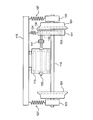
- FIG. 1 is a diagram showing an outline of the configuration of a railcar carriage viewed from the front.
- FIG. 2 is a diagram showing an outline of the configuration of the railcar bogie viewed from directly below.
- the bogie of the railway vehicle includes a gear device (also referred to as “driving device”) 111, an electric motor 113, a bogie frame 115, a joint 117, an axle 119, wheels 121, A bearing 123 is mainly provided.
- the gear device 111 that functions as a speed reducer has a small gear (also referred to as “pinion”) 131 and a large gear 133 that mesh with each other.
- Each of the small gear 131 and the large gear 133 is a spur gear.
- the gear device 111 includes a bearing 135 that rotatably supports the shaft of the small gear 131.
- the bearing 135 prevents the shaft of the small gear 131 from swinging.
- the housing of the bearing 135 is fixed to the housing of the gear device 111.
- the electric motor 113 that is a driving source of the railway vehicle is fixed to the bogie frame 115.
- the rotating shaft 125 of the electric motor 113 is connected to the shaft of the small gear 131 of the gear device 111 via a joint 117. Therefore, the rotational force of the electric motor 113 is transmitted to the small gear 131 of the gear device 111 via the joint 117.
- the large gear 133 of the gear device 111 is fitted coaxially with the axle shaft 119.
- a wheel 121 is also fitted on the axle 119. Accordingly, the rotational force from the electric motor 113 transmitted to the small gear 131 of the gear device 111 is transmitted to the wheel 121 via the large gear 133 and the axle 119.
- the bearing 123 supports the axle shaft 119 rotatably.
- a shaft spring 127 is interposed between the bearing 123 and the bogie frame 115 to absorb vibration (hereinafter referred to as “traveling vibration”) generated as the railway vehicle travels. Even if the shaft spring 127 is bent by the traveling vibration and the carriage frame 115 side and the axle shaft 119 side are relatively displaced, this displacement is absorbed by the bending of the joint 117.
- a variety of loads are applied to the bearing 135 that supports the shaft of the small gear 131 of the gear device 111 due to the bending of the shaft spring 127 or the joint 117 accompanying the traveling vibration.
- the traveling vibration generated during actual traveling of the railway vehicle includes various factors such as environmental factors such as wind that the railway vehicle receives and factors due to track conditions. If the bearing 135 continues to receive such a load, the bearing 135 may be damaged such as creep, brim or pocket wear.
- parameters such as vibration, temperature, torque, displacement, AE (Acoustic Emission) or rotational speed in the shaft of the small gear 131 of the gear device 111 or changes with time thereof are different from those in the normal state. appear.
- the bearing state detection device of the present embodiment is mounted on a railway vehicle, and detects the actual condition regarding damage to the bearing 135 based on a change in parameters according to damage to the bearing 135 during actual traveling of the railway vehicle. .
- the bearing state detection device 10 of the present embodiment is provided in a vehicle body of a railway vehicle including the above-described carriage.
- a measurement value of a sensor 20 that measures at least one of parameters such as vibration, temperature, torque, displacement, AE (Acoustic Emission), and rotation speed is input to the bearing state detection device 10.
- the sensor 20 is provided in the vicinity of the bearing 135 of the gear device 111.
- the sensor 20 may be a microphone (not shown) that collects sound near the bearing 135 of the gear device 111. Transmission of information from the sensor 20 to the bearing state detection device 10 may be wired communication or wireless communication.
- the damage to the bearing 135 is caused by creep, brim or pocket wear.
- creep occurs, the end face of the housing wears, the bearing clearance increases, and the shaft swing increases. After that, when the frequency with which the rolling elements collide in the pocket increases, the cage is damaged.
- tsubaki is generated, the bearing clearance is increased and the shaft runout is increased. After that, when the frequency with which the rolling elements collide in the pocket increases, the cage is damaged.
- the pocket wear progresses, the swing of the cage increases, and the cage is damaged when the frequency of the rolling elements colliding with the pocket increases.
- the bearing 135 is finally damaged, and an event such as the rolling element dropping off occurs.
- the parameter indicated by the information from the sensor 20 changes depending on the content and degree.
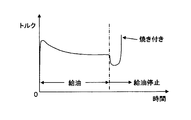
- the sensor 20 measures the torque at the bearing 135.
- the measured value of the sensor 20 rapidly increases after decreasing once, Burn-in occurs.
- the sensor 20 measures the temperature of the bearing 135.
- the measured value of the sensor 20 rises with a characteristic curve. Burn-in occurs.
- FIG. 6 is a block diagram showing an internal configuration of the bearing state detection device 10 of the present embodiment.
- the bearing state detection device 10 includes a filtering processing unit 11, an actual condition analysis unit 13, and a reference data storage unit 15.
- the filtering processing unit 11 filters the measurement value of the sensor 20 and removes parameters other than the parameters by the bearing 135. That is, the measured values of the sensor 20 include not only parameters related to the state of the bearing 135 but also parameters by other components such as the electric motor 113 or the axle 119. In this embodiment, in order to detect the actual condition regarding the damage of the bearing 135, the parameter by components other than the bearing 135 is removed.
- the actual condition analysis unit 13 analyzes the filtered measurement value and analyzes the actual condition regarding damage to the bearing 135.
- ACOUS NAVI registered trademark developed as a bearing abnormal sound digital analysis system may be used for the analysis process.
- the actual condition analysis unit 13 stores, in the reference data storage unit 15, the result of analyzing the measurement value subjected to the filtering process when the bearing 135 is in a normal state during actual traveling of the railway vehicle as reference data.
- the actual condition analysis unit 13 compares the analysis result of the filtered measurement value with the reference data and determines that the bearing 135 is damaged if there is a difference.
- the reference data storage unit 15 stores reference data that is a result of analyzing the measured values filtered when the bearing 135 is in a normal state.
- the reference data is data obtained when the railway vehicle is actually running.
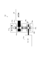
- FIG. 7 is a diagram showing an outline of the configuration of the actual drive tester 130 for confirming the effect of the bearing state detection device 10 of the present embodiment.
- an actual drive tester 130 includes a gear device (also referred to as “drive device”) 111a, a motor (electric motor) 113a, a generator 140, and a vibration sensor 20a.
- the gear device 111a functions as a speed reducer and includes a small gear (also referred to as “pinion”) 131a and a large gear 133a that mesh with each other.
- Each of the small gear 131a and the large gear 133a is a spur gear.
- the gear device 111a includes two bearings 135a and 135b that rotatably support the shaft of the small gear 131a, and two bearings 141a and 141b that rotatably support the shaft of the large gear 133a.
- the bearings 135a and 135b are arranged on both sides of the small gear 131a, and the bearings 141a and 141b are arranged on both sides of the large gear 133a.
- the housings (not shown) of the bearings 135a and 135b and the bearings 141a and 141b are fixed to the casing of the gear device 111a.
- the bearings 135a and 135b prevent the shaft of the small gear 131a from swinging, and the bearings 141a and 141b prevent the shaft of the large gear 133a from swinging.
- the rotational force of the motor 113a is transmitted to the small gear 131a of the gear device 111a.
- the rotational force from the motor 113a transmitted to the small gear 131a is transmitted to the generator 140 via the large gear 133a. Therefore, electric power is generated from the generator 140 when the motor 113a operates.
- the vibration sensor 20a corresponds to the sensor 20 described above, and is provided in the vicinity of the bearings 135a and 135b of the gear device 111a.
- the vibration sensor 20a is used to detect vibrations caused by Tsubaki-fire, pocket wear in the bearings 135a and 135b, and swinging of a cage (one of the components constituting the bearing, which holds a plurality of rolling elements at regular intervals). Used for detection.
- a measurement value of the vibration sensor 20 a is input to the bearing state detection device 10.
- the bearing 135b is a lightly damaged bearing and the bearing 135a is a normal bearing. Further, the test was performed under the condition that the rotation speed was 5680 min ⁇ 1 corresponding to traveling of the actual machine 320 km / h, and the load (torque) to the bearing was 736 N ⁇ m.
- the bearings 141a and 141b are both normal products.
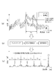
- FIGS. 8A to 8C are diagrams showing vibration analysis results when the bearing is damaged in the actual drive testing machine 130.
- FIG. In the figure, (a) is a diagram showing the strength (vibration level [dB]) in each of the damaged bearing 135b and the normal bearing 135a, with the horizontal axis representing frequency [Hz] and the vertical axis representing strength [dB]. ].
- FFT FastFTransform
- the strength [dB] has a waveform indicated by a solid line.
- the strength [dB] has a waveform indicated by a chain line.
- FIG. 8B shows each process (filtering process, absolute value detection process, envelope detection process) in vibration analysis.
- FIG. 8C is a diagram showing a vibration analysis result of the damaged bearing 135b.
- the horizontal axis represents frequency [Hz] and the vertical axis represents strength [dB].
- Z number of rolling elements
- fr inner ring rotation speed [Hz]
- fc cage rotation speed [Hz]
- fi fr-fc
- fb rolling element rotation speed [Hz]
- dm pitch circle diameter
- Da rolling element diameter
- ⁇ contact angle.
- the present invention is not limited to the configuration of the above-described embodiment, and any configuration can be used as long as the functions shown in the claims or the functions of the configuration of the present embodiment can be achieved. Is also applicable.
Landscapes
- Engineering & Computer Science (AREA)
- Physics & Mathematics (AREA)
- Mechanical Engineering (AREA)
- General Physics & Mathematics (AREA)
- General Engineering & Computer Science (AREA)
- Acoustics & Sound (AREA)
- Chemical & Material Sciences (AREA)
- Combustion & Propulsion (AREA)
- Transportation (AREA)
- Testing Of Devices, Machine Parts, Or Other Structures Thereof (AREA)
- Rolling Contact Bearings (AREA)
Abstract
本発明の課題は、鉄道車両の台車を構成する歯車装置の軸受の損傷に関する実態を高精度に検知可能な軸受状態検知装置を提供することである。 鉄道車両の台車を構成する歯車装置の軸受の状態を検知する軸受状態検知装置は、鉄道車両が実走行時に測定された、軸受の状態に係るパラメータを含む情報に基づいて、軸受の損傷に関する実態を検知する。
Description
本発明は、鉄道車両の台車を構成する歯車装置の軸受の状態を検知する軸受状態検知装置及び軸受状態検知方法に関する。
特許文献1に開示された鉄道車両台車のベアリング異常の振動検出用回転装置は、鉄道車両台車の輪軸に取り付けられたジャーナル軸受や歯車減速装置等の軸受異常を、振動検査により非分解で精度良く検出するための装置である。当該装置を用いた振動検査では、実走行に近い負荷条件で輪軸を回転させて、ジャーナル軸受や歯車減速装置内のコロが発する損傷振動を振動測定センサーにて検出することで、軸受の振動測定を行う。
上記説明した特許文献1の装置は、鉄道車両台車の輪軸を実走行に近い負荷条件で回転させて損傷振動を検出する。しかし、鉄道車両は、特許文献1の装置では再現されない負荷をも受けて走行している。すなわち、鉄道車両が実走行時に受ける負荷には、風や温度等の環境要因及び線路状態による要因を含む多様なパラメータが含まれる。したがって、特許文献1の装置では、実走行に近い負荷条件で輪軸を回転させるとはいえども、実走行時に軸受が実際に受ける負荷に基づいた損傷振動が検出されるわけではないため、軸受の損傷箇所又は損傷程度によっては当該軸受の実態を検出できない可能性がある。
本発明の目的は、鉄道車両の台車を構成する歯車装置の軸受の損傷に関する実態を高精度に検知可能な軸受状態検知装置及び軸受状態検知方法を提供することである。
本発明の上記目的は、下記の構成により達成される。
(1) 鉄道車両の台車を構成する歯車装置の軸受の状態を検知する軸受状態検知装置であって、
前記鉄道車両が実走行時に測定された、前記軸受の状態に係るパラメータを含む情報に基づいて、前記軸受の損傷に関する実態を検知することを特徴とする軸受状態検知装置。
(1) 鉄道車両の台車を構成する歯車装置の軸受の状態を検知する軸受状態検知装置であって、
前記鉄道車両が実走行時に測定された、前記軸受の状態に係るパラメータを含む情報に基づいて、前記軸受の損傷に関する実態を検知することを特徴とする軸受状態検知装置。
(2) 前記鉄道車両が実走行時に測定された情報から前記軸受以外の構成要素によるパラメータを除去するフィルタリング処理部と、
前記フィルタリング処理部によって処理された情報を分析して、前記軸受の損傷に関する実態を解析する実態解析部と、
を備えたことを特徴とする(1)に記載の軸受状態検知装置。
前記フィルタリング処理部によって処理された情報を分析して、前記軸受の損傷に関する実態を解析する実態解析部と、
を備えたことを特徴とする(1)に記載の軸受状態検知装置。
(3) 前記実態解析部は、前記フィルタリング処理部によって処理された情報を分析した結果を、前記軸受が正常状態のときに前記フィルタリング処理部によって処理された情報を分析した結果と比較して、前記軸受の損傷の有無を判別することを特徴とする(2)に記載の軸受状態検知装置。
(4) 前記軸受の状態に係るパラメータを含む情報は、前記歯車装置の前記軸受近傍に設置されたセンサーの測定値であることを特徴とする(1)~(3)のいずれかに記載の軸受状態検知装置。
(5) 前記軸受の状態に係るパラメータを含む情報は、振動、温度、トルク、変位、AE(Acoustic Emission)及び回転速度の少なくともいずれか一つの情報であることを特徴とする(1)~(4)のいずれかに記載の軸受状態検知装置。
(6) 鉄道車両の台車を構成する歯車装置の軸受の状態を検知する軸受状態検知方法であって、
前記鉄道車両が実走行時に測定された、前記軸受の状態に係るパラメータを含む情報に基づいて、前記軸受の損傷に関する実態を検知することを特徴とする軸受状態検知方法。
前記鉄道車両が実走行時に測定された、前記軸受の状態に係るパラメータを含む情報に基づいて、前記軸受の損傷に関する実態を検知することを特徴とする軸受状態検知方法。
本発明に係る軸受状態検知装置及び軸受状態検知方法によれば、鉄道車両の台車を構成する歯車装置の軸受の実態を高精度に検知することができる。
以下、本発明に係る軸受状態検知装置及び軸受状態検知方法の実施形態について、図面を参照して説明する。なお、以下説明する軸受状態検知装置は、鉄道車両の台車を構成する歯車装置の軸受の状態を検知する装置であって、鉄道車両に搭載される。
図1は、鉄道車両の台車を正面方向から見た構成の概要を示す図である。図2は、鉄道車両の台車を真下から見た構成の概要を示す図である。図1及び図2に示すように、鉄道車両の台車は、歯車装置(「駆動装置」ともいう)111と、電動機113と、台車枠115と、継手117と、車軸119と、車輪121と、軸受123とを主に備える。
減速機として機能する歯車装置111は、互いに噛合する小歯車(「ピニオン」ともいう)131及び大歯車133を有する。小歯車131及び大歯車133はそれぞれ平歯車である。また、歯車装置111は、小歯車131の軸を回転自在に支承する軸受135を有する。この軸受135によって、小歯車131の軸の振れ回りが防止される。軸受135のハウジングは、歯車装置111の筐体に固定されている。
鉄道車両の駆動源である電動機113は、台車枠115に固定されている。電動機113の回転軸125は、継手117を介して歯車装置111の小歯車131の軸に連結されている。したがって、電動機113の回転力は、継手117を介して歯車装置111の小歯車131に伝達される。歯車装置111の大歯車133は、車軸119と同軸に嵌着されている。また、車軸119には車輪121も嵌着されている。したがって、歯車装置111の小歯車131に伝達された電動機113からの回転力は、大歯車133及び車軸119を介して車輪121に伝達される。
軸受123は、車軸119を回転自在に支承するものである。軸受123と台車枠115の間には、鉄道車両の走行に伴い発生する振動(以下「走行振動」という)を吸収するための軸ばね127が介設されている。なお、走行振動によって軸ばね127が撓んで台車枠115側と車軸119側とが相対変位しても、継手117が撓むことによってこの変位は吸収される。
走行振動に伴う軸ばね127又は継手117の撓みによって、歯車装置111の小歯車131の軸を支承する軸受135には多様な荷重がかかる。さらに、鉄道車両の実走行時に発生する走行振動には、鉄道車両が受ける風等の環境要因や線路状態による要因等の多様な要因が含まれる。こうした荷重を軸受135が受け続けると、軸受135には、クリープ、つば焼き又はポケット摩耗等の損傷が発生し得る場合がある。また、軸受135に損傷が発生すると、歯車装置111の小歯車131の軸における振動、温度、トルク、変位、AE(Acoustic Emission)又は回転速度等のパラメータ又はその経時変化が正常時とは異なって表れる。なお、損傷した軸受135が破損に至って、軸受135の部品が歯車装置111内に飛び散ると、歯車装置111まで破損してしまう。しかも、軸受135の損傷から破損に至るまでの事象は急速に進行する場合もあるため、軸受135が破損に至る前段階での損傷状態の時点でその実態を検知できた方が望ましい。このため、本実施形態の軸受状態検知装置は、鉄道車両に搭載され、当該鉄道車両の実走行中における軸受135の損傷に応じたパラメータの変化に基づいて、軸受135の損傷に関する実態を検知する。
以下、本実施形態の軸受状態検知装置について説明する。本実施形態の軸受状態検知装置10は、図3に示すように、上記説明した台車を含む鉄道車両の車体内に設けられる。軸受状態検知装置10には、振動、温度、トルク、変位、AE(Acoustic Emission)及び回転速度等のパラメータの少なくともいずれか一つを測定するセンサー20の測定値が入力される。センサー20は、歯車装置111の軸受135近傍に設けられる。なお、センサー20は、歯車装置111の軸受135近傍の音を集音するマイク(図示せず)であっても良い。センサー20から軸受状態検知装置10への情報の伝送は、有線通信でも無線通信でも良い。
軸受135の損傷は、クリープ、つば焼き又はポケット摩耗等によって発生する。クリープが発生すると、ハウジングの端面が摩耗してベアリングすきまが大きくなり、軸の振れ回りが大きくなる。その後、転動体がそのポケット内で衝突する頻度が高くなると保持器の破損に至る。つば焼きが発生した場合も同様に、ベアリングすきまが大きくなり、軸の振れ回りが大きくなる。その後、転動体がそのポケット内で衝突する頻度が高くなると保持器の破損に至る。また、ポケット摩耗が進行すると、保持器の振れ回りが大きくなり、転動体がそのポケット内で衝突する頻度が高くなると保持器の破損に至る。保持器が破損すると、最終的に軸受135の破損に至り、転動体が脱落する等の事象が発生する。
このように、軸受135の損傷から破損に至る過程には段階があるが、その内容や程度によってセンサー20からの情報が示すパラメータに変化が表れる。例えば、図4に示す実験例では、センサー20は軸受135におけるトルクを測定する。図4の実験データが示すように、軸受135の回転速度が一定値に維持された状態で軸受135に対する給油を停止すると、センサー20の測定値は一旦下がった後に急激に増加し、軸受135には焼き付きが発生する。また、図5に示す実験例では、センサー20は軸受135の温度を測定する。図5の実験データが示すように、軸受135の回転速度が一定値に維持された状態で軸受135に対する給油を停止すると、センサー20の測定値は特徴的なカーブで上昇し、軸受135には焼き付きが発生する。
図4及び図5に示したように、軸受135が損傷する際のセンサー20の測定値には正常時とは異なる変化が表れる。したがって、軸受状態検知装置10は、鉄道車両の実走行中に得られたセンサー20の測定値を分析することで、軸受135の損傷に関する実態を検知する。図6は、本実施形態の軸受状態検知装置10の内部構成を示すブロック図である。図6に示すように、軸受状態検知装置10は、フィルタリング処理部11と、実態解析部13と、基準データ記憶部15とを備える。
フィルタリング処理部11は、センサー20の測定値をフィルタリング処理して、軸受135によるパラメータ以外を除去する。すなわち、センサー20の測定値には、軸受135の状態に係るパラメータだけでなく、電動機113又は車軸119等の他の構成要素によるパラメータも含まれる。本実施形態では、軸受135の損傷に関する実態を検知するため、軸受135以外の構成要素によるパラメータが除去される。
実態解析部13は、フィルタリング処理された測定値を分析して、軸受135の損傷に関する実態を解析する。なお、分析処理には、軸受異常音デジタル解析システムとして開発された「ACOUS NAVI」(登録商標)が用いられても良い。実態解析部13は、鉄道車両の実走行時、軸受135が正常状態のときフィルタリング処理された測定値を分析した結果を、基準データとして基準データ記憶部15に格納する。実態解析部13は、フィルタリング処理した測定値の分析結果を基準データと比較して相違があれば、軸受135が損傷したと判定する。例えば、実態解析部13は、軸受135以外の構成要素(小歯車131等)の振動が比較的少ない、鉄道車両の定速惰性走行時に、歯車装置111の軸受135近傍に設けられたセンサー20から得られた振動測定信号を解析処理したデータ(例えば、実効値又は周波数パワースペクトル)を、所定の周波数帯域における正常時のデータと比較することにより、軸受135の異常を判定する。なお、所定の周波数帯域は、歯車装置111の特徴的周波数である。逆に、実態解析部13は、当該比較を行って相違がなければ、軸受135は正常と判定する。
基準データ記憶部15は、軸受135が正常状態のときフィルタリング処理された測定値を分析した結果である基準データを記憶する。なお、基準データは、鉄道車両が実走行時に得られたデータである。
本実施形態の軸受状態検知装置10の効果を確認するため、損傷程度が軽い軸受と正常な軸受を実機駆動装置試験機130に組込み、比較検証試験を実施した。
図7は、本実施形態の軸受状態検知装置10の効果を確認するための実機駆動装置試験機130の構成の概要を示す図である。同図において、実機駆動装置試験機130は、歯車装置(「駆動装置」ともいう)111aと、モータ(電動機)113aと、発電機140と、振動センサー20aとを備える。歯車装置111aは、減速機として機能し、互いに噛合する小歯車(「ピニオン」ともいう)131aと大歯車133aを有する。小歯車131a及び大歯車133aはそれぞれ平歯車である。歯車装置111aは、小歯車131aの軸を回転自在に支承する2つの軸受135a,135bと、大歯車133aの軸を回転自在に支承する2つの軸受141a,141bとを有する。軸受135a,135bは、小歯車131aを挟むように、その両側に配置されており、軸受141a,141bは、大歯車133aを挟むように、その両側に配置されている。
図7は、本実施形態の軸受状態検知装置10の効果を確認するための実機駆動装置試験機130の構成の概要を示す図である。同図において、実機駆動装置試験機130は、歯車装置(「駆動装置」ともいう)111aと、モータ(電動機)113aと、発電機140と、振動センサー20aとを備える。歯車装置111aは、減速機として機能し、互いに噛合する小歯車(「ピニオン」ともいう)131aと大歯車133aを有する。小歯車131a及び大歯車133aはそれぞれ平歯車である。歯車装置111aは、小歯車131aの軸を回転自在に支承する2つの軸受135a,135bと、大歯車133aの軸を回転自在に支承する2つの軸受141a,141bとを有する。軸受135a,135bは、小歯車131aを挟むように、その両側に配置されており、軸受141a,141bは、大歯車133aを挟むように、その両側に配置されている。
軸受135a,135b及び軸受141a,141bそれぞれのハウジング(図示略)は、歯車装置111aの筐体に固定されている。軸受135a,135bによって、小歯車131aの軸の振れ回りが防止され、軸受141a,141bによって、大歯車133aの軸の振れ回りが防止される。モータ113aの回転力は、歯車装置111aの小歯車131aに伝達される。小歯車131aに伝達されたモータ113aからの回転力は、大歯車133aを介して発電機140に伝達される。したがって、モータ113aが動作することで、発電機140から電力が発生する。振動センサー20aは、上述したセンサー20に相当するもので、歯車装置111aの軸受135a,135b近傍に設けられている。振動センサー20aは、軸受135a,135bにおけるつば焼、ポケット摩耗、保持器(軸受を構成する部品の1つで、複数の転動体を一定間隔で保持するもの)の振れ回り等に起因する振動の検出に用いられる。振動センサー20aの測定値が軸受状態検知装置10に入力される。
この比較検証試験では、例えば軸受135bを損傷程度の軽い軸受とし、軸受135aを正常な軸受としている。また、回転数を実機320km/hの走行に相当する5680min-1とし、軸受への負荷(トルク)を736N・mとした条件で試験を実施した。なお、軸受141a,141bは、双方とも正常品であるとする。
図8(a)~(c)は、実機駆動装置試験機130における軸受損傷時の振動解析結果を示す図である。同図において、(a)は、損傷品の軸受135bと正常品の軸受135aそれぞれにおける強度(振動レベル[dB])を示す図であり、横軸が周波数[Hz]、縦軸が強度[dB]である。なお、軸受の振動解析には、高速フーリエ変換(FFT:Fast Fourier Transform)を用いた。正常品の軸受135aでは、その強度[dB]が実線で示す波形となった。損傷品の軸受135bでは、その強度[dB]が鎖線で示す波形となった。また、図8の(b)は、振動解析における各処理(フィルタリング処理、絶対値検波処理、包絡検波処理)を示す。また、図8の(c)は、損傷品の軸受135bの振動解析結果を示す図であり、横軸が周波数[Hz]、縦軸が強度[dB]である。
軸受135bのつば焼けに起因する軸受損傷の兆候として、特定の周波数帯域fwで強度(振動レベル[dB])に大きな差が生じる(図8の(a))。また、フィルタリング処理、絶対値検波処理及びエンベロープ処理(包絡検波処理)した振動解析では、軸受135bの保持器(複数の転動体を一定間隔で保持するもの)の公転周期に起因する特徴周波数「fc」が一定間隔で検出された(図8の(c))。さらに、つば焼けの程度により、軸受135bの外輪に起因する特徴周波数成分である「Zfc成分」も見られた(図8の(c))。
また、ポケット摩耗(保持器の転動体を収容する部分)に起因する軸受損傷の兆候としては、保持器の公転周期である特徴周波数成分「fc」が現れたが、その強度は弱く、またその数(「fc」の数)も少なかった。
また、ポケット摩耗が進行し、保持器と保持器が振れ回るような状態である軸受損傷の状態においては、保持器の外径面と軸受外輪内径面が接触し、外輪に起因する特徴周波数成分である「Zfc」成分が顕著に現れた。
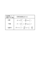
図9は、軸受における傷の位置と特定周波数成分[Hz]との関係を示す図である。同図において、振動発生に起因する位置が内輪にある場合、特定周波数成分[Hz]は、Zfiで示す数式で表され、振動発生に起因する位置が外輪にある場合、特定周波数成分[Hz]は、Zfcで示す数式で表され、振動発生に起因する位置が転動体にある場合、特定周波数成分[Hz]は、2fbで示す数式で表される。ここで、Z:転動体の数、fr:内輪回転速度[Hz]、fc:保持器回転速度[Hz]、fi=fr-fc、fb:転動体自転速度[Hz]、dm:ピッチ円直径、Da:転動体直径、α:接触角である。
上述のように、振動センサー20aでの検知にて、FFT振動解析処理、フィルタリング処理及び絶対値検波処理を行った後、エンベロープ処理した振動解析を行うことで、軸受135bのつば焼け、軸受135bの保持器のポケット摩耗、軸受135bの保持器の振れ回り等の異常を検知可能と確認した。また、小歯車131aと大歯車133aかみ合いによる発生周波数は計算可能であるので、あらかじめこの発生周波数を対象から除外することで、それぞれの振動特徴から、どのような起因(つば焼け、ポケット摩耗、保持器の振れ回り)により損傷に進行していくかの予兆判断が可能と確認した。
以上説明したように、本実施形態の軸受状態検知装置10は、鉄道車両の実走行中に得られたセンサー20からの情報に基づいて、軸受135の損傷に起因するパラメータの変化の有無を判定することによって、軸受135の損傷に関する実態を検知する。このように、軸受135の異常に係る予兆診断を行うため、軸受135の異常状態を迅速かつ高精度に検知できる。その結果、時間的なロスがなく高効率及び低コストを実現可能なメンテナンスを実現でき、さらには最適な鉄道車両の運行制御を実現できる。また、軸受135が破損に至る前段階での損傷の可能性を検知できるため、定期メンテナンス前の早い段階での処置が可能となる。したがって、軸受135を含む歯車装置111の安全性及び信頼性の向上に大きく寄与できる。
なお、本発明は、上記実施形態の構成に限られるものではなく、特許請求の範囲で示した機能、又は本実施形態の構成が持つ機能が達成できる構成であればどのようなものであっても適用可能である。
本発明を詳細にまた特定の実施態様を参照して説明したが、本発明の精神と範囲を逸脱することなく様々な変更や修正を加えることができることは当業者にとって明らかである。
本出願は、2013年11月5日出願の日本特許出願(特願2013-229107)及び2014年10月30日出願の日本特許出願(特願2014-221953)に基づくものであり、その内容はここに参照として取り込まれる。
10 軸受状態検知装置
11 フィルタリング処理部
13 実態解析部
15 基準データ記憶部
20 センサー
111 歯車装置
113 電動機
115 台車枠
117 継手
119 車軸
121 車輪
123 軸受
131 小歯車
133 大歯車
135 軸受
11 フィルタリング処理部
13 実態解析部
15 基準データ記憶部
20 センサー
111 歯車装置
113 電動機
115 台車枠
117 継手
119 車軸
121 車輪
123 軸受
131 小歯車
133 大歯車
135 軸受
Claims (6)
- 鉄道車両の台車を構成する歯車装置の軸受の状態を検知する軸受状態検知装置であって、
前記鉄道車両が実走行時に測定された、前記軸受の状態に係るパラメータを含む情報に基づいて、前記軸受の損傷に関する実態を検知することを特徴とする軸受状態検知装置。 - 前記鉄道車両が実走行時に測定された情報から前記軸受以外の構成要素によるパラメータを除去するフィルタリング処理部と、
前記フィルタリング処理部によって処理された情報を分析して、前記軸受の損傷に関する実態を解析する実態解析部と、
を備えたことを特徴とする請求項1に記載の軸受状態検知装置。 - 前記実態解析部は、前記フィルタリング処理部によって処理された情報を分析した結果を、前記軸受が正常状態のときに前記フィルタリング処理部によって処理された情報を分析した結果と比較して、前記軸受の損傷の有無を判別することを特徴とする請求項2に記載の軸受状態検知装置。
- 前記軸受の状態に係るパラメータを含む情報は、前記歯車装置の前記軸受近傍に設置されたセンサーの測定値であることを特徴とする請求項1~3のいずれか一項に記載の軸受状態検知装置。
- 前記軸受の状態に係るパラメータを含む情報は、振動、温度、トルク、変位、AE(Acoustic Emission)及び回転速度の少なくともいずれか一つの情報であることを特徴とする請求項1~4のいずれか一項に記載の軸受状態検知装置。
- 鉄道車両の台車を構成する歯車装置の軸受の状態を検知する軸受状態検知方法であって、
前記鉄道車両が実走行時に測定された、前記軸受の状態に係るパラメータを含む情報に基づいて、前記軸受の損傷に関する実態を検知することを特徴とする軸受状態検知方法。
Priority Applications (3)
| Application Number | Priority Date | Filing Date | Title |
|---|---|---|---|
| EP14860113.1A EP3067683B1 (en) | 2013-11-05 | 2014-11-05 | Bearing state detection device and bearing state detection method |
| CN201480060682.3A CN105765362A (zh) | 2013-11-05 | 2014-11-05 | 轴承状态检测装置和轴承状态检测方法 |
| US15/034,226 US20160282223A1 (en) | 2013-11-05 | 2014-11-05 | Bearing state detection device and bearing state detection method |
Applications Claiming Priority (4)
| Application Number | Priority Date | Filing Date | Title |
|---|---|---|---|
| JP2013229107 | 2013-11-05 | ||
| JP2013-229107 | 2013-11-05 | ||
| JP2014-221953 | 2014-10-30 | ||
| JP2014221953A JP6413642B2 (ja) | 2013-11-05 | 2014-10-30 | 軸受状態検知装置及び軸受状態検知方法 |
Publications (1)
| Publication Number | Publication Date |
|---|---|
| WO2015068737A1 true WO2015068737A1 (ja) | 2015-05-14 |
Family
ID=53041514
Family Applications (1)
| Application Number | Title | Priority Date | Filing Date |
|---|---|---|---|
| PCT/JP2014/079360 Ceased WO2015068737A1 (ja) | 2013-11-05 | 2014-11-05 | 軸受状態検知装置及び軸受状態検知方法 |
Country Status (5)
| Country | Link |
|---|---|
| US (1) | US20160282223A1 (ja) |
| EP (1) | EP3067683B1 (ja) |
| JP (1) | JP6413642B2 (ja) |
| CN (1) | CN105765362A (ja) |
| WO (1) | WO2015068737A1 (ja) |
Cited By (2)
| Publication number | Priority date | Publication date | Assignee | Title |
|---|---|---|---|---|
| JP2015111113A (ja) * | 2013-11-05 | 2015-06-18 | 日本精工株式会社 | 軸受状態検知装置及び軸受状態検知方法 |
| US11630030B2 (en) | 2012-08-22 | 2023-04-18 | Transportation Ip Holdings, Llc | Sensor signal processing system and method |
Families Citing this family (11)
| Publication number | Priority date | Publication date | Assignee | Title |
|---|---|---|---|---|
| CN107843429B (zh) * | 2016-09-19 | 2021-08-31 | 舍弗勒技术股份两合公司 | 轴承状态监测控制方法及控制装置、监测设备、监测方法 |
| EP3444585B1 (en) * | 2017-08-17 | 2020-05-27 | ALSTOM Transport Technologies | Method for determining a state of a bearing, module for determining a state of a bearing, railway vehicle and system |
| JP7016298B2 (ja) * | 2018-07-11 | 2022-02-21 | 公益財団法人鉄道総合技術研究所 | 検出器 |
| JP6507297B1 (ja) * | 2018-09-07 | 2019-04-24 | オークマ株式会社 | 転がり軸受の異常診断方法及び異常診断装置、異常診断プログラム |
| JP7306968B2 (ja) * | 2019-11-06 | 2023-07-11 | 株式会社日本製鋼所 | 異常検知装置、異常検知方法及びコンピュータプログラム |
| JP7306967B2 (ja) * | 2019-11-06 | 2023-07-11 | 株式会社日本製鋼所 | 異常検知装置、異常検知方法及びコンピュータプログラム |
| JP7242518B2 (ja) * | 2019-12-16 | 2023-03-20 | 株式会社東芝 | 非破壊検査方法及び非破壊検査システム |
| JP7631996B2 (ja) * | 2021-03-31 | 2025-02-19 | 日本精工株式会社 | 軸受状態診断装置 |
| JP7584602B2 (ja) * | 2022-03-01 | 2024-11-15 | 三菱電機株式会社 | 転がり軸受の異常診断方法 |
| JP7471523B2 (ja) * | 2022-03-01 | 2024-04-19 | 三菱電機株式会社 | 転がり軸受の異常検知装置、転がり軸受の異常診断装置、及び列車異常監視システム |
| DE102023200663A1 (de) * | 2023-01-27 | 2024-08-01 | Siemens Mobility GmbH | Verfahren zur Ermittlung des Zustands einer beweglichen Komponente in einem Fahrzeug |
Citations (6)
| Publication number | Priority date | Publication date | Assignee | Title |
|---|---|---|---|---|
| JP2901666B2 (ja) | 1989-11-10 | 1999-06-07 | 光洋精工株式会社 | 鉄道車両用軸受装置の診断装置 |
| JP3284967B2 (ja) | 1998-04-23 | 2002-05-27 | 住友金属工業株式会社 | 鉄道車両用駆動装置 |
| JP2006275954A (ja) * | 2005-03-30 | 2006-10-12 | Railway Technical Res Inst | 軸受監視システム、及び軸受監視プログラム |
| JP2008134115A (ja) * | 2006-11-28 | 2008-06-12 | Nsk Ltd | 異常診断装置 |
| JP4427400B2 (ja) | 2004-07-05 | 2010-03-03 | 住金関西工業株式会社 | 鉄道車両台車のベアリング異常の振動検出用回転装置 |
| JP4802975B2 (ja) | 2006-10-30 | 2011-10-26 | 住友金属工業株式会社 | 鉄道車両用歯車装置の温度予測方法 |
Family Cites Families (9)
| Publication number | Priority date | Publication date | Assignee | Title |
|---|---|---|---|---|
| US6967586B2 (en) * | 2000-10-20 | 2005-11-22 | Sankyo Seiki Mfg. Co., Ltd. | Bearing test method, bearing test device, bearing monitoring device and storage device |
| EP1624206B1 (en) * | 2003-05-13 | 2010-03-17 | JTEKT Corporation | Bearing management system and method for the same |
| JP2006077938A (ja) * | 2004-09-13 | 2006-03-23 | Nsk Ltd | 異常診断装置 |
| WO2006030786A1 (ja) * | 2004-09-13 | 2006-03-23 | Nsk Ltd. | 異常診断装置及び異常診断方法 |
| MX2009013288A (es) * | 2007-06-04 | 2010-02-24 | Eaton Corp | Sistema y metodo para deteccion de falla de cojinete usando cancelacion de ruido de corriente del estator. |
| JP5455298B2 (ja) * | 2007-11-06 | 2014-03-26 | オークマ株式会社 | 軸受状態診断装置 |
| JP4961417B2 (ja) * | 2008-12-17 | 2012-06-27 | 株式会社テイエルブイ | 機器状態情報収集方法、及び、それに用いる機器状態情報収集キット |
| JP5725833B2 (ja) * | 2010-01-04 | 2015-05-27 | Ntn株式会社 | 転がり軸受の異常診断装置、風力発電装置および異常診断システム |
| JP6413642B2 (ja) * | 2013-11-05 | 2018-10-31 | 日本精工株式会社 | 軸受状態検知装置及び軸受状態検知方法 |
-
2014
- 2014-10-30 JP JP2014221953A patent/JP6413642B2/ja not_active Ceased
- 2014-11-05 WO PCT/JP2014/079360 patent/WO2015068737A1/ja not_active Ceased
- 2014-11-05 EP EP14860113.1A patent/EP3067683B1/en active Active
- 2014-11-05 US US15/034,226 patent/US20160282223A1/en not_active Abandoned
- 2014-11-05 CN CN201480060682.3A patent/CN105765362A/zh active Pending
Patent Citations (6)
| Publication number | Priority date | Publication date | Assignee | Title |
|---|---|---|---|---|
| JP2901666B2 (ja) | 1989-11-10 | 1999-06-07 | 光洋精工株式会社 | 鉄道車両用軸受装置の診断装置 |
| JP3284967B2 (ja) | 1998-04-23 | 2002-05-27 | 住友金属工業株式会社 | 鉄道車両用駆動装置 |
| JP4427400B2 (ja) | 2004-07-05 | 2010-03-03 | 住金関西工業株式会社 | 鉄道車両台車のベアリング異常の振動検出用回転装置 |
| JP2006275954A (ja) * | 2005-03-30 | 2006-10-12 | Railway Technical Res Inst | 軸受監視システム、及び軸受監視プログラム |
| JP4802975B2 (ja) | 2006-10-30 | 2011-10-26 | 住友金属工業株式会社 | 鉄道車両用歯車装置の温度予測方法 |
| JP2008134115A (ja) * | 2006-11-28 | 2008-06-12 | Nsk Ltd | 異常診断装置 |
Cited By (2)
| Publication number | Priority date | Publication date | Assignee | Title |
|---|---|---|---|---|
| US11630030B2 (en) | 2012-08-22 | 2023-04-18 | Transportation Ip Holdings, Llc | Sensor signal processing system and method |
| JP2015111113A (ja) * | 2013-11-05 | 2015-06-18 | 日本精工株式会社 | 軸受状態検知装置及び軸受状態検知方法 |
Also Published As
| Publication number | Publication date |
|---|---|
| JP2015111113A (ja) | 2015-06-18 |
| EP3067683A4 (en) | 2016-11-02 |
| CN105765362A (zh) | 2016-07-13 |
| EP3067683B1 (en) | 2019-10-09 |
| JP6413642B2 (ja) | 2018-10-31 |
| EP3067683A1 (en) | 2016-09-14 |
| US20160282223A1 (en) | 2016-09-29 |
Similar Documents
| Publication | Publication Date | Title |
|---|---|---|
| JP6413642B2 (ja) | 軸受状態検知装置及び軸受状態検知方法 | |
| JP4477242B2 (ja) | 鉄道車軸ハブユニット | |
| CN104990709B (zh) | 用于检测机车轴承故障的方法 | |
| US9423290B2 (en) | Abnormality diagnostic device for rolling bearing, wind turbine generation apparatus and abnormality diagnostic system | |
| JP5832442B2 (ja) | レール車両の、少なくとも一つの輪軸を有している台車の状態を監視するための方法 | |
| JP7027782B2 (ja) | 転がり軸受の異常診断装置 | |
| US11148689B2 (en) | Vehicle monitoring system | |
| WO2006030786A1 (ja) | 異常診断装置及び異常診断方法 | |
| JP4527585B2 (ja) | 軸受監視システム、及び軸受監視プログラム | |
| JP2012042271A (ja) | 走行速度検出装置 | |
| KR101495841B1 (ko) | 전동 열차의 진동 측정 장치 | |
| CN102798413B (zh) | 一种铁道动态检测系统 | |
| JP6714844B2 (ja) | 異常診断方法 | |
| Liang et al. | An analysis of abnormal vibration and noise caused by shaft coupling misalignment of high-speed train | |
| Bosso et al. | Design of a test rig for railway axle-boxes | |
| JP2009255822A (ja) | 鉄道車両の脱線乃至は浮き上り検知装置 | |
| EP3556636A2 (en) | Sensor signal processing system and method | |
| JPH03152436A (ja) | 鉄道車両用軸受の診断方法 | |
| KR20150044141A (ko) | 철도차량용 감속장치의 이상유무 감지장치 및 감지방법 | |
| CN113125148B (zh) | 一种便携式封闭齿轮箱探测装置及异常判定方法 | |
| Yin et al. | Dynamic Modeling and Vibration Analysis of Gearbox Bearings for a High-Speed Train With Polygonal Wheel | |
| Vyplaven et al. | Analysis of Frequency and Time Characteristics of the Vibration Acceleration Signal of Traction Electric Motor of Motor Car | |
| Gu et al. | Dynamic modeling and simulation of irregular faults in axle box bearings of high-speed trains | |
| Chatterton et al. | Diagnostics of rolling element bearings for the traction system of high speed trains: Experimental evidences | |
| JP2025006072A (ja) | 転がり軸受の異常検出装置及び異常検出方法 |
Legal Events
| Date | Code | Title | Description |
|---|---|---|---|
| 121 | Ep: the epo has been informed by wipo that ep was designated in this application |
Ref document number: 14860113 Country of ref document: EP Kind code of ref document: A1 |
|
| REEP | Request for entry into the european phase |
Ref document number: 2014860113 Country of ref document: EP |
|
| WWE | Wipo information: entry into national phase |
Ref document number: 2014860113 Country of ref document: EP |
|
| WWE | Wipo information: entry into national phase |
Ref document number: 15034226 Country of ref document: US |
|
| NENP | Non-entry into the national phase |
Ref country code: DE |