WO2015071958A1 - リモートコントローラー - Google Patents
リモートコントローラー Download PDFInfo
- Publication number
- WO2015071958A1 WO2015071958A1 PCT/JP2013/080548 JP2013080548W WO2015071958A1 WO 2015071958 A1 WO2015071958 A1 WO 2015071958A1 JP 2013080548 W JP2013080548 W JP 2013080548W WO 2015071958 A1 WO2015071958 A1 WO 2015071958A1
- Authority
- WO
- WIPO (PCT)
- Prior art keywords
- digital object
- display
- remote controller
- digital
- processing unit
- Prior art date
- Legal status (The legal status is an assumption and is not a legal conclusion. Google has not performed a legal analysis and makes no representation as to the accuracy of the status listed.)
- Ceased
Links
Images









Classifications
-
- F—MECHANICAL ENGINEERING; LIGHTING; HEATING; WEAPONS; BLASTING
- F24—HEATING; RANGES; VENTILATING
- F24F—AIR-CONDITIONING; AIR-HUMIDIFICATION; VENTILATION; USE OF AIR CURRENTS FOR SCREENING
- F24F11/00—Control or safety arrangements
- F24F11/62—Control or safety arrangements characterised by the type of control or by internal processing, e.g. using fuzzy logic, adaptive control or estimation of values
-
- F—MECHANICAL ENGINEERING; LIGHTING; HEATING; WEAPONS; BLASTING
- F24—HEATING; RANGES; VENTILATING
- F24F—AIR-CONDITIONING; AIR-HUMIDIFICATION; VENTILATION; USE OF AIR CURRENTS FOR SCREENING
- F24F11/00—Control or safety arrangements
- F24F11/30—Control or safety arrangements for purposes related to the operation of the system, e.g. for safety or monitoring
-
- F—MECHANICAL ENGINEERING; LIGHTING; HEATING; WEAPONS; BLASTING
- F24—HEATING; RANGES; VENTILATING
- F24F—AIR-CONDITIONING; AIR-HUMIDIFICATION; VENTILATION; USE OF AIR CURRENTS FOR SCREENING
- F24F11/00—Control or safety arrangements
- F24F11/50—Control or safety arrangements characterised by user interfaces or communication
- F24F11/52—Indication arrangements, e.g. displays
- F24F11/523—Indication arrangements, e.g. displays for displaying temperature data
-
- F—MECHANICAL ENGINEERING; LIGHTING; HEATING; WEAPONS; BLASTING
- F24—HEATING; RANGES; VENTILATING
- F24F—AIR-CONDITIONING; AIR-HUMIDIFICATION; VENTILATION; USE OF AIR CURRENTS FOR SCREENING
- F24F11/00—Control or safety arrangements
- F24F11/50—Control or safety arrangements characterised by user interfaces or communication
- F24F11/56—Remote control
-
- F—MECHANICAL ENGINEERING; LIGHTING; HEATING; WEAPONS; BLASTING
- F24—HEATING; RANGES; VENTILATING
- F24F—AIR-CONDITIONING; AIR-HUMIDIFICATION; VENTILATION; USE OF AIR CURRENTS FOR SCREENING
- F24F11/00—Control or safety arrangements
- F24F11/50—Control or safety arrangements characterised by user interfaces or communication
- F24F11/61—Control or safety arrangements characterised by user interfaces or communication using timers
-
- F—MECHANICAL ENGINEERING; LIGHTING; HEATING; WEAPONS; BLASTING
- F24—HEATING; RANGES; VENTILATING
- F24F—AIR-CONDITIONING; AIR-HUMIDIFICATION; VENTILATION; USE OF AIR CURRENTS FOR SCREENING
- F24F11/00—Control or safety arrangements
- F24F11/62—Control or safety arrangements characterised by the type of control or by internal processing, e.g. using fuzzy logic, adaptive control or estimation of values
- F24F11/63—Electronic processing
- F24F11/64—Electronic processing using pre-stored data
-
- F—MECHANICAL ENGINEERING; LIGHTING; HEATING; WEAPONS; BLASTING
- F24—HEATING; RANGES; VENTILATING
- F24F—AIR-CONDITIONING; AIR-HUMIDIFICATION; VENTILATION; USE OF AIR CURRENTS FOR SCREENING
- F24F11/00—Control or safety arrangements
- F24F11/62—Control or safety arrangements characterised by the type of control or by internal processing, e.g. using fuzzy logic, adaptive control or estimation of values
- F24F11/63—Electronic processing
- F24F11/65—Electronic processing for selecting an operating mode
- F24F11/67—Switching between heating and cooling modes
-
- F—MECHANICAL ENGINEERING; LIGHTING; HEATING; WEAPONS; BLASTING
- F24—HEATING; RANGES; VENTILATING
- F24F—AIR-CONDITIONING; AIR-HUMIDIFICATION; VENTILATION; USE OF AIR CURRENTS FOR SCREENING
- F24F11/00—Control or safety arrangements
- F24F11/50—Control or safety arrangements characterised by user interfaces or communication
- F24F11/52—Indication arrangements, e.g. displays
-
- F—MECHANICAL ENGINEERING; LIGHTING; HEATING; WEAPONS; BLASTING
- F24—HEATING; RANGES; VENTILATING
- F24F—AIR-CONDITIONING; AIR-HUMIDIFICATION; VENTILATION; USE OF AIR CURRENTS FOR SCREENING
- F24F2110/00—Control inputs relating to air properties
- F24F2110/10—Temperature
-
- F—MECHANICAL ENGINEERING; LIGHTING; HEATING; WEAPONS; BLASTING
- F24—HEATING; RANGES; VENTILATING
- F24F—AIR-CONDITIONING; AIR-HUMIDIFICATION; VENTILATION; USE OF AIR CURRENTS FOR SCREENING
- F24F2110/00—Control inputs relating to air properties
- F24F2110/20—Humidity
-
- F—MECHANICAL ENGINEERING; LIGHTING; HEATING; WEAPONS; BLASTING
- F24—HEATING; RANGES; VENTILATING
- F24F—AIR-CONDITIONING; AIR-HUMIDIFICATION; VENTILATION; USE OF AIR CURRENTS FOR SCREENING
- F24F2120/00—Control inputs relating to users or occupants
- F24F2120/10—Occupancy
Definitions
- the present invention relates to a remote controller.
- Patent Document 1 Since the conventional technology described in Patent Document 1 is intended to save power, a user interface has not been configured for the purpose of user-friendliness. Therefore, the conventional technique described in Patent Document 1 sometimes displays a user interface different from the usage environment. Therefore, the prior art described in Patent Document 1 does not display an optimal user interface according to the use environment.
- Patent Document 1 since the prior art described in Patent Document 1 aims at power saving, power saving is realized by performing an operation of hiding character information rather than intuitive understanding. It was. Therefore, the prior art described in Patent Document 1 does not display an intuitive user interface according to the use environment.
- Patent Document 1 has a problem that it cannot supply an optimal and intuitive user interface according to the use environment.
- the present invention has been made to solve the above-described problems, and an object thereof is to provide a remote controller capable of supplying an optimal and intuitive user interface according to the use environment. It is.
- a remote controller is a remote controller that controls an air conditioner including an outdoor unit and an indoor unit, a storage unit that stores data of different types of digital objects, and displays the digital objects
- a touch panel display configured to detect an operation of the digital object
- a control processing unit that controls the touch panel display, wherein the control processing unit Among the objects, the digital object corresponding to the operation assumed from the ambient environment of the indoor unit or the operation history of the operation input unit is displayed.
- the present invention can configure the display content of the user interface according to the operation content assumed from the surrounding environment or the operation history. Therefore, the present invention has an effect that it is possible to provide a remote controller that provides an optimal and intuitive user interface according to the use environment.
- step of describing the program for performing the operation of the embodiment of the present invention is a process performed in time series in the order described, but it is not always necessary to process in time series.
- the processing executed may be included.
- each block diagram described in this embodiment may be considered as a hardware block diagram or a software functional block diagram.
- each block diagram may be realized by hardware such as a circuit device, or may be realized by software executed on an arithmetic device such as a processor (not shown).
- each block in the block diagram described in the present embodiment only needs to perform its function, and the configuration may not be separated by each block.
- items that are not particularly described are the same as those in the first to sixth embodiments, and the same functions and configurations are described using the same reference numerals.
- each of Embodiments 1 to 6 may be implemented independently or in combination. In either case, the advantageous effects described below can be obtained.
- various specific setting examples described in this embodiment are merely examples, and are not particularly limited thereto.
- the system represents the entire apparatus composed of a plurality of apparatuses.
- a network refers to a mechanism in which at least two devices are connected and information can be transmitted from one device to another.
- Devices that communicate via a network may be independent devices, or may be internal blocks that constitute one device.
- the communication may be communication in which wireless communication and wired communication are mixed as well as wireless communication and wired communication. For example, wireless communication may be performed in a certain section, and wired communication may be performed in another space. Further, communication from one device to another device may be performed by wired communication, and communication from another device to one device may be performed by wireless communication.
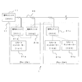
- FIG. 1 is a diagram illustrating an example of a schematic configuration of an air-conditioning system 1 according to Embodiment 1 of the present invention.
- the first embodiment of the present invention is optimal for the use environment by configuring the display content of the user interface 201 described later according to the operation content assumed from the surrounding environment or the operation history.
- Intuitive user interface 201 is provided. The details will be described below.
- the air conditioning system 1 includes an outdoor unit 11, an indoor unit 21a, an indoor unit 21b, an indoor unit 21c, a remote controller 31a, a remote controller 31b, and a remote controller 31c. ing.
- the outdoor unit 11, the indoor unit 21 a, the indoor unit 21 b, and the indoor unit 21 c are connected via a refrigerant pipe 43.
- the outdoor unit 11, the indoor unit 21a, the indoor unit 21b, and the indoor unit 21c are connected via a transmission line 41.
- the indoor unit 21a, the indoor unit 21b, and the remote controller 31a are connected via a transmission line 41.
- the indoor unit 21c, the remote controller 31b, and the remote controller 31c are connected via a transmission line 41.
- group # 1 is set in the indoor unit 21a, the indoor unit 21b, and the remote controller 31a.
- group # 3 is set in the indoor unit 21c, the remote controller 31b, and the remote controller 31c.
- group # 1 the operations of the indoor unit 21a and the indoor unit 21b are controlled by various signals supplied from the remote controller 31a, and the outdoor unit 11 is controlled accordingly.
- group # 2 the operation of the indoor unit 21c is controlled by various signals supplied from the remote controller 31b or the remote controller 31c, and the outdoor unit 11 is controlled accordingly. That is, since the outdoor unit 11 is interlocked by any one of the indoor units 21a to 21c operating, a refrigeration cycle is formed as described later.
- the indoor unit 21a, the indoor unit 21b, and the indoor unit 21c will be referred to as the indoor unit 21 unless otherwise distinguished.
- the remote controller 31a, the remote controller 31b, and the remote controller 31c are not particularly distinguished, they are referred to as the remote controller 31.
- the transmission line 41 described above is an example in which the communication medium is wired, but is not particularly limited thereto.
- the transmission line 41 may be a wireless communication medium.
- the communication protocol is not particularly limited. For example, communication may be performed between the outdoor unit 11 and the indoor unit 21 using a dedicated communication protocol via a wired or wireless communication medium, or may be performed using a general-purpose communication protocol. Good.
- communication may be performed between the indoor unit 21 and the remote controller 31 using a dedicated communication protocol via a wired or wireless communication medium.
- communication may be performed between the indoor unit 21 and the remote controller 31 using a general-purpose communication protocol via a wired or wireless communication medium.
- communication may be performed between the indoor unit 21 and the remote controller 31 through a communication protocol defined by RFC (Request for Comments) via a wireless communication medium.
- the remote controller 31 is not a dedicated device for controlling the indoor unit 21, but a virtual device that is virtually realized as an application such as a smartphone, as long as the remote controller 31 has a function described below. There may be.
- the indoor unit 21 when various commands are supplied to the indoor unit 21 from the remote controller 31, the indoor unit 21 operates in cooperation with the outdoor unit 11 in accordance with the supplied various commands. For example, since the outdoor unit 11 and the indoor unit 21 are connected via the refrigerant pipe 43, a refrigeration cycle is formed by repeating the compression and expansion of the refrigerant. As a result, the indoor unit 21 harmonizes the air in the air-conditioning target space.
- the air conditioning system 1 includes a refrigerant circuit (not shown), and supplies air that is air conditioned to the air-conditioning target space in the cooling operation or the heating operation.
- the air conditioning system 1 supplies cold air during cooling operation.
- the air conditioning system 1 supplies warm air during heating operation, for example.
- a refrigerant circuit (not shown) is filled with a refrigerant. Therefore, the filled refrigerant circulates in the refrigerant pipe 43 to form a vapor compression refrigeration cycle.
- the outdoor unit 11 includes a compressor, an outdoor unit side heat exchanger, an outdoor unit side fan, an outdoor unit side expansion valve, and a four-way valve (all not shown). It has.
- the indoor unit 21 includes an indoor unit side heat exchanger, an indoor unit side fan, and an indoor unit side expansion valve (all not shown).
- a compressor, a four-way valve, an outdoor unit side heat exchanger, an outdoor unit side expansion valve, an indoor unit side expansion valve, and an indoor unit side heat exchanger are connected via a refrigerant pipe 43.
- the outdoor unit 11 is a compressor, a four-way valve, an outdoor unit side heat exchanger, an outdoor unit side based on various commands supplied from the outside, for example, various commands supplied from the remote controller 31 via the indoor unit 21.
- the fan and the outdoor unit side expansion valve are controlled.
- the outdoor unit 11 drives the compressor based on various commands supplied from the remote controller 31, compresses the refrigerant sucked into the compressor, and discharges it with an arbitrary pressure.
- the outdoor unit 11 operates the four-way valve based on various commands supplied from the remote controller 31 and switches the path of the refrigerant pipe 43, whereby the high-temperature and high-pressure refrigerant discharged from the compressor is transferred to the outdoor unit side heat exchanger. Or it supplies to an indoor unit side heat exchanger, and switches between cooling operation and heating operation.
- the outdoor unit 11 exchanges heat between the refrigerant passing through the outdoor unit side heat exchanger and the air around the outdoor unit side heat exchanger.
- the outdoor unit 11 drives the outdoor unit side fan based on various commands supplied from the remote controller 31, supplies air for heat exchange to the outdoor unit side heat exchanger, and performs heat exchange of the outdoor unit side heat exchanger. Promote.
- the outdoor unit 11 controls the flow rate of the refrigerant flowing through the refrigerant pipe 43 by adjusting the opening degree of the outdoor unit side expansion valve based on various commands supplied from the remote controller 31.
- the indoor unit 21 is based on various commands supplied from the outside, for example, various commands supplied from the remote controller 31 via the indoor unit 21, and the indoor unit side heat exchanger, the indoor unit side fan, and the indoor unit side Control the expansion valve.
- the indoor unit 21 exchanges heat between the refrigerant passing through the indoor unit side heat exchanger and the air around the indoor unit side heat exchanger.
- the indoor unit 21 controls the flow rate of the refrigerant flowing through the refrigerant pipe 43 by adjusting the opening of the indoor unit side expansion valve based on various commands supplied from the remote controller 31.
- the address is an address between devices in order to identify one device in the network among the outdoor unit 11, the indoor unit 21a, the indoor unit 21b, the indoor unit 21c, the remote controller 31a, the remote controller 31b, and the remote controller 31c. A value that does not overlap is set.
- “051” is set as an address in the outdoor unit 11.
- “001” is set as an address.
- “002” is set as an address.
- the indoor unit 21c “003” is set as an address.
- “101” is set as an address.
- “103” is set as an address.
- “153” is set as an address.
- the address set in the outdoor unit 11 is, for example, “051” to “100”, but is not particularly limited thereto.
- the addresses set in the indoor unit 21 are, for example, “001” to “050”, but are not particularly limited thereto.
- the addresses set in the remote controller 31 are, for example, “101” to “200”, but are not particularly limited thereto.
- each address may be set by, for example, a rotary switch (not shown).
- the numerical value of the address demonstrated above is an example, Comprising: It does not specifically limit to these.
- the number of outdoor units 11, the number of indoor units 21, and the number of remote controllers 31 described above are merely examples, and are not particularly limited thereto.
- the air conditioning system 1 may include one outdoor unit 11, one indoor unit 21, and one remote controller 31.
- the address setting method as described above is an example, and the present invention is not particularly limited to this.
- FIG. 2 is a diagram showing an example of a schematic configuration of the remote controller 31 according to Embodiment 1 of the present invention.
- FIG. 3 is a diagram showing an example of a detailed configuration of the remote controller 31 according to Embodiment 1 of the present invention. It is assumed that the outdoor unit 11 and the indoor unit 21 shown in FIG. 1 or 2 are air conditioners.
- the indoor unit 21 and the outdoor unit 11 are connected via a refrigerant pipe 43.
- Each of the outdoor unit 11, the indoor unit 21, and the remote controller 31 transmits and receives various signals via the transmission line 41.
- the indoor unit 21 and the remote controller 31 are connected by a power line 42.
- the indoor unit 21 supplies power to the remote controller 31 via the power line 42. Therefore, the remote controller 31 operates by receiving power from the indoor unit 21.
- the transmission line 41 is assumed to perform wired communication between the indoor unit 21 and the remote controller 31 as described above, but is not particularly limited thereto.
- the transmission line 41 may be a communication medium. Therefore, since the transmission line 41 may be a wireless medium, wireless communication may be performed between the indoor unit 21 and the remote controller 31.
- the indoor unit 21 may use air as the power transmission medium.
- the indoor unit 21 may wirelessly supply power to the remote controller 31. That is, the indoor unit 21 may supply power to the remote controller 31 by performing wireless power feeding.
- the type of wireless power feeding is not particularly limited, and for example, an electromagnetic induction method, a resonance coupling method, an electric field coupling method, or the like may be used.
- the indoor unit 21 is used as a power supply source from the outside to the remote controller 31
- the present invention is not particularly limited thereto. Power may be directly supplied to the remote controller 31 from an external power supply source (not shown), for example, a commercial power supply.
- the remote controller 31 may be provided with a secondary battery or a primary battery so that the remote controller 31 can execute various functions even when power is not supplied from the outside.
- the secondary battery is not particularly limited, and may be a lithium ion secondary battery, for example.
- a primary battery is not specifically limited, For example, what is necessary is just a lithium battery etc.
- the remote controller 31 includes a communication unit 51, a power supply unit 53, a touch panel display 55, a storage unit 65, a sensor module 67, a control processing unit 69, and the like.
- the touch panel display 55 includes, for example, an operation input unit 61 and a display unit 63.
- the operation input unit 61 is a device that inputs an operation content from the outside as a user interface 201 to be described later. However, the configuration of the operation input unit 61 is different depending on the operation principle of the touch panel.
- the touch panel is composed of matrix switches.
- the touch panel is configured by a surface formed of switches formed by electrodes arranged at regular intervals in the vertical and horizontal directions like a grid, electrodes are formed in two upper and lower layers, respectively.
- the operation input unit 61 is configured by the upper and lower two layers of power described above.
- the touch panel is configured by a resistive film method.
- the touch panel is composed of a metal thin film in which electrodes formed in two upper and lower layers are transparent electrodes. A predetermined resistance is applied to the metal thin film, and a voltage is applied to one of the two metal thin films facing each other.
- a voltage corresponding to the operated position is generated on the second surface. If the generated voltage is detected, the operated position is detected as an analog quantity. That is, the operation input unit 61 is configured by the metal thin film described above.
- the touch panel is configured by a surface acoustic wave method.
- the touch panel is configured by providing piezoelectric elements at a plurality of corners on a substrate such as highly rigid glass.
- a vibration wave is generated.
- the operation input unit 61 is configured by the piezoelectric element described above.
- the touch panel is configured by an infrared method.
- the touch panel uses the infrared LED as a light source, the infrared light emitted from the infrared LED is blocked, and the light receiving element detects the blocked position, whereby the position information touched by the operator is detected.
- the operation input unit 61 includes the infrared LED and the light receiving element described above.
- the touch panel is configured by a capacitive method.
- the touch panel is formed of a driving electrode, a receiving electrode, and a dielectric covering the receiving electrode, and an electric field is generated from the driving electrode, so that an operator's contact end, for example, a fingertip, a dielectric, The change in capacitance between the two is captured by the receiving electrode, and the position information in contact with the operator is detected.
- the operation input unit 61 includes a drive electrode and a reception electrode.
- the touch panel is configured by an electromagnetic induction method.
- the touch panel is provided with a magnetic field detection sensor below the screen and causes electromagnetic induction at a location where a device that generates a magnetic field such as an electronic pen touches the screen.
- the operation input unit 61 includes a time detection sensor.
- the operation input unit 61 is not particularly limited thereto.
- the imaging device captures the position of a physical object such as a finger that operates the digital object 211. May be.
- the operation input unit 61 is an imaging device (not shown).
- the operation input unit 61 may be a user interface 201 to which a control command corresponding to a user operated is input, and the embodiment thereof is not particularly limited.
- the display unit 63 is a device that outputs display contents to the outside as a user interface 201 described later.
- the display unit 63 is, for example, a liquid crystal display.
- the display unit 63 is not limited to a liquid crystal display.
- the display unit 63 may be an organic EL (electroluminescence) display.
- the user interface 201 to be described later may be composed of an organic EL display and a touch panel.
- the display unit 63 may be a stereoscopic video or a reproduced image of a stereoscopic image realized as a hologram.
- the display unit 63 may be configured by a reproduction device realized by a laser irradiation device, a hologram, and the like, and an imaging device that detects a position where the reproduction image is touched.
- the display unit 63 may be any user interface 201 that allows the user to operate or displays an operation result, and the embodiment thereof is not particularly limited.
- the power supply unit 53 converts the supplied power into power used inside the remote controller 31. For example, when AC power is supplied, the power supply unit 53 internally converts the DC power into a usable range. Moreover, when direct-current power is supplied, the power supply part 53 converts into direct-current power in the usable range inside. Moreover, when electric power is supplied by a secondary battery or a primary battery, the power supply part 53 should just be comprised as a control function for acquiring electric power stably from a secondary battery or a primary battery.
- the communication unit 51 modulates various signals supplied from the control processing unit 69 into transmission signals, and transmits the modulated transmission signals to the indoor unit 21 via the transmission line 41.
- the communication unit 51 demodulates various signals supplied from the indoor unit 21 into reception signals, and supplies the demodulated reception signals to the control processing unit 69.
- the storage unit 65 temporarily stores data using, for example, a rewritable RAM (Random Access Memory).
- the storage unit 65 uses, for example, a read-only ROM (Read Only Memory) to store various modules configured by various processing programs, various parameters, and various data corresponding to operation contents such as a digital object 211 described later. I remember it. That is, the storage unit 65 includes a RAM and a ROM. A detailed example of various data stored in the storage unit 65 will be described later with reference to FIG.
- the sensor module 67 detects the surrounding environment of the remote controller 31, for example.
- the sensor module 67 includes, for example, a human sensor module 81, a temperature sensor module 83, a humidity sensor module 85, an illuminance sensor module 87, and the like.
- the human sensor module 81 detects the presence or absence of a person.
- the temperature sensor module 83 detects the room temperature.
- the humidity sensor module 85 detects indoor humidity.
- the illuminance sensor module 87 detects room illuminance.
- the sensor module 67 may be only the temperature sensor module 83. Further, the sensor module 67 may include a human sensor module 81 and a temperature sensor module 83. Further, as one form of the configuration of the sensor module 67, the temperature sensor module 83 and the humidity sensor module 85 may be integrally configured. A detailed example of the sensor module 67 will be described later with reference to FIG.
- the control processing unit 69 is constituted by, for example, a processor, reads various data from the storage unit 65, and processes the various data read based on the frequency of an oscillator (not shown) that supplies a constant clock.
- the control processing unit 69 processes various signals supplied from the operation input unit 61.
- the control processing unit 69 processes various signals output to the display unit 63.
- the control processing unit 69 processes various signals supplied from the sensor module 67.
- the control processing unit 69 stores various data in the storage unit 65.
- the control processing unit 69 supplies various signals to the communication unit 51.
- Various modules virtually realized when the control processing unit 69 processes various signals will be described with reference to FIG.
- control processing unit 69 is configured virtually by an operation state determination module 101, an ambient environment determination module 102, an operation history determination module 103, an image processing module 105, and the like according to execution of various processes. Is done.
- the operating state determination module 101 determines whether or not the indoor unit 21 is operating based on various information supplied from the communication unit 51.
- the operating state determination module 101 determines the operating state of the indoor unit 21 based on various information stored in the storage unit 65, for example, various information stored in the operating state data storage area 181 as described later. You may judge.
- the ambient environment determination module 102 determines the ambient environment of the remote controller 31.
- the ambient environment determination module 102 includes, for example, a presence determination module 111, a temperature determination module 112, a humidity determination module 113, an illuminance determination module 114, and the like.
- the presence determination module 111 determines whether there is a person around the remote controller 31 based on various signals supplied from the human sensor module 81.
- the temperature determination module 112 determines the ambient temperature of the remote controller 31 based on various signals supplied from the temperature sensor module 83 and a preset temperature threshold.
- the preset temperature threshold value will be described later in detail, but there are a plurality of threshold values.
- the remote controller 31 is a cooling determination temperature for assuming that the cooling operation is performed. It is the heating determination temperature for assuming that the operation is performed.
- the humidity determination module 113 determines the humidity around the remote controller 31 based on various signals supplied from the humidity sensor module 85 and a preset humidity threshold.
- the illuminance sensor module 87 determines the illuminance around the remote controller 31 based on various signals supplied from the illuminance sensor 161 and a preset illuminance threshold.
- the ambient environment determination module 102 uses the output of the sensor module 67 and performs determinations corresponding to various sensors provided in the sensor module 67. For example, if the sensor module 67 is provided with a wind speed sensor, an air volume sensor, or the like, the ambient environment determination module 102 performs a determination corresponding to them. For example, when the sensor module 67 is provided with a sensor that measures a human brain wave, the ambient environment determination module 102 associates the human brain wave with an action pattern corresponding to the human brain wave. Should be implemented.
- the ambient environment determination module 102 is stored in various information held in the storage unit 65, for example, in the ambient environment data storage area 182 as described later.
- the surrounding environment may be determined by referring to various information.
- the operation history determination module 103 determines the operation history of the remote controller 31.
- the operation history determination module 103 includes, for example, an operation mode determination module 116 and the like.
- the operation mode determination module 116 refers to the past operation history based on various information stored in the storage unit 65, for example, various information stored in the operation history data storage area 184, as will be described later. The operation mode operated most recently is determined.
- the image processing module 105 supplies digital object data to the display unit 63 and the storage unit 65 as data for generating a digital image.
- the image processing module 105 determines various states of the digital object 211 based on the digital object data held in the storage unit 65.
- the image processing module 105 includes an object state determination module 118 and an object drawing module 119.
- the object state determination module 118 determines various states of the digital object 211 based on various information held in an operation history data storage area 184 assigned to the storage unit 65 described later, for example. For example, as described later, the object drawing module 119 generates digital object data based on various types of information stored in the default data storage area 183 and the operation history data storage area 184 allocated to the storage unit 65. The generation result is supplied to the display unit 63, and a digital image is displayed on the display unit 63.
- Each storage area such as an operation state data storage area 181, an ambient environment data storage area 182, a default data storage area 183, and an operation history data storage area 184 is allocated to the storage unit 65.
- the operating state data storage area 181 stores the operating state data of the indoor unit 21 among various signals supplied from the communication unit 51, for example.
- the operating state data storage area 181 is configured by a ring buffer as a logical configuration, for example.
- the supplied signals may be held in time series, and when there is no area to be held, the holding may be resumed from the area where the first holding is started.
- the surrounding environment data storage area 182 for example, various signals supplied from the sensor module 67 or various signals supplied from the ambient environment determination module 102 are stored.
- the surrounding environment data storage area 182 is configured by, for example, a ring buffer as a logical configuration, and holds various signals supplied in time series. When there is no area to hold, the surrounding environment data storage area 182 starts to hold first. The holding may be resumed from the area.
- the presence / absence determination result of the person supplied from the human sensor module 81 is stored in the ambient environment data storage area 182 in chronological order for each presence determination cycle of the human sensor module 81. Since the human presence determination results supplied from the human sensor module 81 are sequentially stored in time series, the remote controller 31 can refer to the human presence determination results based on the current detection results, The presence / absence determination result of a person can also be referred to immediately before, for example, based on the detection result 30 seconds ago.
- the presence / absence determination cycle of the human sensor module 81 is set finely, the immediately preceding presence / absence determination can be determined in a shorter time. Also, when it is assumed that the frequency of people going in and out at night or the like when people go in and out decreases, the presence / absence determination cycle of the human sensor module 81 may be set larger.
- the digital object data includes, for example, object shape data, object position data, object size data, object type data, and object color space data.
- the object shape data for example, various pieces of information for specifying a shape for displaying the digital object data via the display unit 63 are set.
- the object shape data includes data related to normal display image information and data related to highlight display image information.
- object position data for example, various pieces of information for specifying a position when digital object data is displayed via the display unit 63 are set.
- object size data for example, various pieces of information for specifying the size when the digital object data is displayed via the display unit 63 are set.
- object type data for example, various types of information for specifying the type of digital object data are set.
- the object color space data for example, various types of information for specifying a color for displaying the digital object data via the display unit 63 are set.
- the object color space data is composed of hue data, saturation data, lightness data, and luminance data.
- the brightness data and the brightness data are selected according to an algorithm for generating the color of the digital object data. For example, when an HSV (Hue Saturation Value) color space is used for color generation, hue data, saturation data, and brightness data are applied. Further, for example, when an HLS (Hue Saturation Lightness) color space is used for color generation, hue data, saturation data, and luminance data are applied.
- HSV Human Saturation Value
- HLS Human Saturation Lightness
- object shape data, object position data, object size data, and object color space data may be associated with each object type data.
- the object shape data, the object position data, the object size data, the object type data, the object color space data, and the like may be linked to each other and may have a logical configuration that can be referred to.
- the operation history data storage area 184 stores, for example, operation mode data, operation mode related data, digital object data, and the like.
- the operation mode data corresponds to the operation mode among the digital objects 211 and the like operated by the operation input unit 61, for example, and is data related to the designated operation mode.
- the operation mode related data is, for example, various data related to the designated operation mode. For example, when the cooling operation is designated as the operation mode, the operation mode related data is various data corresponding to the setting contents during the cooling operation. Similarly, when the heating operation is designated as the operation mode, the operation mode related data is various data corresponding to the setting contents during the heating operation.
- the digital object data stored in the operation history data storage area 184 includes object state data, object shape data, object position data, object size data, object type data, object color space data, and the like.
- object state data for example, various drawing histories of digital object data are held in time series.
- object shape data, the object position data, the object size data, the object type data, and the object color space data are the same data as described above, and the most recent state is held.
- operation history data described above is an example and is not particularly limited thereto.
- the human sensor module 81 includes a pyroelectric infrared sensor 131, a signal processing unit 132, and a human detection unit 133.
- the pyroelectric infrared sensor 131 includes, for example, a Fresnel lens, a pyroelectric element, and a junction field effect transistor.
- the pyroelectric infrared sensor 131 supplies the infrared light collected by the Fresnel lens to the pyroelectric element, and varies the gate voltage of the junction field effect transistor in accordance with the output of the pyroelectric element.
- the output voltage of the transistor is changed, and the output voltage thus changed is supplied to the signal processing unit 132 as the output of the pyroelectric infrared sensor 131.
- the number of pyroelectric elements is not particularly limited.
- the pyroelectric infrared sensor 131 may be provided with one pyroelectric element.
- the pyroelectric infrared sensor 131 may be configured by arranging a plurality of pyroelectric elements.
- the signal processing unit 132 includes an LPF (Low Pass Filter), an amplifier, and an A / D converter.
- the signal processing unit 132 reduces noise of the output voltage supplied from the pyroelectric infrared sensor 131 and converts it into a digital signal. This is supplied to the detection unit 133.
- the LPF for example, removes power supply noise from the minute output voltage of the pyroelectric infrared sensor 131 and supplies it to the amplifier as an analog signal.
- the amplifier amplifies the analog signal and supplies it to the A / D converter.
- the A / D converter converts the amplified analog signal into a digital signal at a preset sampling period and supplies the digital signal to the human detection unit 133.
- the human detection unit 133 includes a threshold setting unit and a comparison unit. The human detection unit 133 compares whether or not the digital signal exceeds the threshold set by the threshold setting unit, and supplies the comparison result to the control processing unit 69.
- the temperature sensor module 83 includes a temperature sensor 141 and a signal processing unit 142.
- the temperature sensor 141 is composed of a plurality of thermistors, for example.
- the temperature sensor 141 changes its resistance value due to a temperature change, and supplies the change in the resistance value to the signal processing unit 142 as an analog signal.
- the signal processing unit 142 includes an LPF, an amplifier, and an A / D converter.
- the LPF removes the noise component of the analog signal supplied from the temperature sensor 141 and supplies it to the amplifier.
- the amplifier amplifies the analog signal and supplies it to the A / D converter.
- the A / D converter converts the amplified analog signal into a digital signal at a preset sampling cycle, and supplies the digital signal to the control processing unit 69.
- the humidity sensor module 85 includes a humidity sensor 151 and a signal processing unit 152.
- the humidity sensor 151 is composed of, for example, a plurality of sets of electrostatic capacitance type sensors provided with an upper electrode, a lower electrode, and a polymer moisture sensitive material.
- the humidity sensor 151 changes the capacitance of the polymer moisture-sensitive material provided between the upper electrode and the lower electrode in accordance with the humidity change, and the change in the capacitance is sent to the signal processing unit 152 as an analog signal.
- the signal processing unit 152 includes an LPF, an amplifier, and an A / D converter.
- the LPF removes the noise component of the analog signal supplied from the humidity sensor 151 and supplies it to the amplifier.
- the amplifier amplifies the analog signal and supplies it to the A / D converter.
- the A / D converter converts the amplified analog signal into a digital signal at a preset sampling cycle, and supplies the digital signal to the control processing unit 69.
- the illuminance sensor module 87 includes an illuminance sensor 161 and a signal processing unit 162.
- the illuminance sensor 161 is composed of a plurality of photodiodes, for example.
- the illuminance sensor 161 supplies the detection results of the plurality of photodiodes to the signal processing unit 162 as analog signals.
- the signal processing unit 162 includes an LPF, an amplifier, and an A / D converter.
- the LPF removes the noise component of the analog signal supplied from the illuminance sensor 161 and supplies it to the amplifier.
- the amplifier amplifies the analog signal and supplies it to the A / D converter.
- the A / D converter converts the amplified analog signal into a digital signal at a preset sampling cycle, and supplies the digital signal to the control processing unit 69.
- control processing unit 69 may perform various calculations, and the functional configuration is not particularly limited. Further, for example, the various areas allocated in the storage unit 65 are merely examples, and it is only necessary that the control processing unit 69 can refer to the data acquisition destination and the data storage destination. Further, the sensor module 67 may have a simple configuration as compared with the configuration described above.
- the human sensor module 81 includes only the pyroelectric infrared sensor 131 and may not have any other configuration.
- the process corresponding to the signal processing unit 132 may be provided with an interface between the sensor module 67 and the control processing unit 69 separately.
- the process corresponding to the human detection unit 133 may be executed by the control processing unit 69.
- the temperature sensor module 83 may be configured with only the temperature sensor 141
- the humidity sensor module 85 may be configured with only the humidity sensor 151
- the illuminance sensor module 87 may be configured with only the illuminance sensor 161.
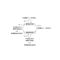
- FIG. 4 is a diagram illustrating an example of state transition between the normal configuration state and the special configuration state according to Embodiment 1 of the present invention.
- the digital object 211 and the like are assumed to be in a normal configuration state and a special configuration state.
- the normal configuration state is a configuration when digital object data is drawn with default settings.
- the special configuration state is a configuration when the display content of the user interface 201 is drawn according to the operation content assumed from the surrounding environment or the operation history. For example, the state transition described below is performed.
- step S11 If there is no special configuration mode command (step S11), the control processing unit 69 maintains the normal configuration state. When there is a special configuration mode command (step S12), the control processing unit 69 makes a transition to the special configuration state.
- step S13 If the preset time has not elapsed (step S13), the control processing unit 69 maintains the special configuration state. Further, when there is a special configuration display command (step S13), the control processing unit 69 maintains the special configuration state. If the preset time has elapsed (step S14), the control processing unit 69 makes a transition to the normal configuration state. Further, when there is no special configuration display command (step S14), the control processing unit 69 makes a transition to the normal configuration state.
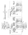
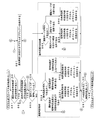
- FIG. 5 is a flowchart for explaining an operation example of the remote controller 31 according to the first embodiment of the present invention.
- steps S23 to S25 are temperature determination processes in which the digital object 211 and the like are displayed according to the surrounding environment.
- processing from step S27 to step S29 is an operation history determination process in which the digital object 211 or the like is displayed according to the operation history. That is, the operation described with reference to FIG. 5 is a process for displaying the digital object 211 or the like corresponding to the surrounding environment or the operation history. Note that, for example, the presence / absence of a special configuration mode command and the operating status of the indoor unit 21 are used as triggers for shifting to processing according to the surrounding environment or operation history.
- Step S21 The remote controller 31 determines whether or not there is a special configuration mode command. When there is a special configuration mode command, the remote controller 31 proceeds to step S22. On the other hand, if there is no special configuration mode command, the remote controller 31 returns to step S21.
- the special configuration mode command may be, for example, a command transmitted from a terminal existing outside such as a smartphone.
- a terminal existing outside such as a smartphone.
- the user wants to perform air conditioning from 7:00 pm.
- the user supplies a special configuration mode command to the remote controller 31 from a smartphone or the like
- the user enters the digital object 211 or the like displayed in the special configuration mode after entering the room where the remote controller 31 is provided. Can be operated.
- achieves the virtual environment of the remote controller 31 is installed in the smart phone etc.
- the special configuration mode command may be commanded from various time information set in advance.
- the remote controller 31 may shift to the special configuration mode based on a preset action history or a person schedule. Specifically, when it is determined from a person's action history or a person's schedule that a user uses an air-conditioned room from 9 am, the remote controller 31 shifts to a special configuration mode at 9 am May be.
- the special configuration mode command may be in accordance with a human presence / absence determination result.
- the remote controller 31 may shift to a state where there is a special configuration mode command at the timing when the presence / absence determination result of the person becomes absent from the absence.
- the case where such a person's presence determination result is used is later mentioned using FIG.8 and FIG.9 as Embodiment 2.
- FIG.8 and FIG.9 Embodiment 2.
- Step S22 The remote controller 31 determines whether or not the indoor unit 21 is operating. When the indoor unit 21 is not operating, the remote controller 31 proceeds to step S23. On the other hand, when the indoor unit 21 is operating, the remote controller 31 proceeds to step S27.
- the state where the indoor unit 21 is not in operation includes not only the state where the power to the indoor unit 21 is cut off but also the state where the indoor unit 21 is on standby for operation.
- the refrigerant stagnation operation may be performed in the indoor unit 21 and the outdoor unit 11.
- the state in which the indoor unit 21 is operating is a state in which a refrigeration cycle is formed in the indoor unit 21 and the outdoor unit 11 by operating the outdoor unit 11 as the indoor unit 21 operates. It is assumed that it means a state where air conditioning is implemented.
- Step S23 The remote controller 31 determines which is the room temperature. When the room temperature is not less than the heating determination temperature and not more than the cooling determination temperature, the remote controller 31 proceeds to step S30. If the room temperature is less than the heating determination temperature, the remote controller 31 proceeds to step S24. If the room temperature is higher than the cooling determination temperature, the remote controller 31 proceeds to step S25.
- Step S24 The remote controller 31 displays the digital object 211 corresponding to the setting content at the start of the heating operation, and proceeds to step S26.
- Step S25 The remote controller 31 displays the digital object 211 corresponding to the setting content at the start of the cooling operation, and proceeds to step S26.
- Step S26 The remote controller 31 determines whether a preset time has elapsed.
- the remote controller 31 ends the process when a preset time has elapsed. On the other hand, if the preset time has not elapsed, the remote controller 31 returns to step S22.
- the preset time is, for example, 5 minutes, but is not particularly limited thereto. In other words, when the time that the user is supposed to use the remote controller 31 has elapsed, the remote controller 31 may shift from the special configuration mode to the normal configuration mode.
- Step S27 The remote controller 31 determines which operation mode is in effect. If the operation mode is other than cooling and heating, the remote controller 31 proceeds to step S30. When the operation mode is heating, the remote controller 31 proceeds to step S28. If the operation mode is cooling, the remote controller 31 proceeds to step S29.
- Step S28 The remote controller 31 displays the digital object 211 corresponding to the setting content at the time of heating operation, and proceeds to step S26.
- Step S29 The remote controller 31 displays the digital object 211 corresponding to the setting content during the cooling operation, and proceeds to step S26.
- Step S30 The remote controller 31 displays the digital object 211 corresponding to the normal configuration, and proceeds to step S26.
- FIG. 6 is a diagram showing a display example of the digital object 211 in the normal configuration state assuming cooling in the first embodiment of the present invention.
- the remote controller 31 displays the digital object 211 as the user interface 201. Therefore, when the digital object 211 displayed on the user interface 201 is operated, an operation corresponding to the designated digital object 211 is executed.
- the user interface 201 includes, for example, a liquid crystal display that functions as the display unit 63 and a touch panel that functions as the operation input unit 61.
- the digital object 211 indicates any one of the digital object 211a to the digital object 211g.
- the digital object 211a is drawn, for example, as a lower triangular button, and a control command for lowering the set temperature is supplied to the control processing unit 69 when an operation such as pressing is performed.
- the digital object 211b is drawn as an upper triangle button, and a control command for raising the set temperature by an operation such as pressing is supplied to the control processing unit 69.
- the digital object 211c is, for example, drawn as a left-facing button, and a control command for calling a virtual image hidden on the left side of the screen by an operation such as pressing is supplied to the control processing unit 69.
- the digital object 211d is drawn as a button in which the characters “Driving” are written, and a control command for driving by being pressed is supplied to the control processing unit 69.
- the digital object 211e is drawn as a button in which the characters “cooling mode” are written, and a control command to display the setting content corresponding to the cooling mode is supplied to the control processing unit 69 when an operation such as pressing is performed. Is done.
- the digital object 211f is drawn as a button in which the characters “menu” are written, and a control command for displaying the setting content corresponding to the menu is supplied to the control processing unit 69 when an operation such as pressing is performed.
- the digital object 211 g is drawn as a right-pointing button, and a control command for calling a virtual image hidden on the right side of the screen by an operation such as pressing is supplied to the control processing unit 69.
- the display configuration described above is an example, and is not particularly limited thereto.
- the number of buttons drawn as the digital object 211, the size of the button, the button color, the button position, and the like do not need to be constant, and may be changed as appropriate according to the situation.
- the control processing unit 69 causes the display unit 63 to display the digital object 211 corresponding to the setting content at the start of the heating operation
- the control processing unit 69 starts from the display example illustrated in FIG.
- the display unit 63 is redrawn with the digital object 211 corresponding to the setting content at the start of heating operation.
- control processing unit 69 displays the digital object 211 corresponding to the setting content at the start of the cooling operation on the display unit 63
- the control processing unit 69 displays the display example shown in FIG. Therefore, the digital object 211 corresponding to the setting contents at the start of the cooling operation is redrawn on the display unit 63 in order to change the setting contents to the setting contents at the start of the cooling operation.
- control processing unit 69 when the control processing unit 69 displays the digital object 211 corresponding to the setting content at the time of heating operation on the display unit 63, the control processing unit 69 starts from the display example shown in FIG. In order to change the setting contents during the heating operation, the digital object 211 corresponding to the setting contents during the heating operation is redrawn on the display unit 63. Further, for example, as described above, when the control processing unit 69 displays the digital object 211 corresponding to the setting content during the cooling operation on the display unit 63, the control processing unit 69 starts from the display example illustrated in FIG. In order to change the setting contents during the cooling operation, the display unit 63 is redrawn with the digital object 211 corresponding to the setting contents during the cooling operation.
- FIG. 7 is a diagram showing an example of the indoor temperature determination index 530 according to Embodiment 1 of the present invention.
- the indoor temperature determination index 530 is an index for determining the indoor temperature.
- a cooling determination temperature and a heating determination temperature are set, so that the temperature ranges used for determining the indoor temperature are the first temperature region, the second temperature region, and the third temperature region.
- Each is divided into temperature regions.
- a temperature range in which the digital object 211 corresponding to the start of the cooling mode operation is associated with the first temperature region.
- a temperature range that maintains the digital object 211 that is currently displayed is linked to the second temperature region.
- a temperature range in which the digital object 211 corresponding to the start of the heating mode operation is associated with the third temperature region.
- the cooling determination temperature is, for example, a cooling set temperature set via the user interface 201 when the operation mode is the cooling mode.
- the cooling determination temperature may be a cooling set temperature transmitted from a smartphone or the like.
- the cooling determination temperature may be a cooling set temperature set in advance in an operation schedule or the like.
- the heating determination temperature is, for example, a heating set temperature set via the user interface 201 when the operation mode is the heating mode.
- the heating determination temperature may be a heating set temperature transmitted from a smartphone or the like.
- the heating determination temperature may be a heating set temperature that is set in advance in an operation schedule or the like.
- the room temperature exceeds the cooling determination temperature, and therefore belongs to the first temperature region.
- the remote controller 31 displays the digital object 211 corresponding to the setting content at the start of the cooling operation.
- the room temperature is lower than the heating determination temperature, and thus belongs to the third temperature region.
- the remote controller 31 displays the digital object 211 corresponding to the setting content at the start of the heating operation.
- the room temperature is between the cooling determination temperature and the heating determination temperature, and therefore belongs to the second temperature region.
- the remote controller 31 displays the digital object 211 corresponding to the normal configuration.
- the cooling determination temperature may be lower than the heating determination temperature. Further, the heating determination temperature may exceed the cooling determination temperature. Only one of the cooling determination temperature and the heating determination temperature may be set.
- the remote controller 31 determines whether the operation state of the indoor unit 21 is cooling or heating based on the operation history of the operation mode, but is not particularly limited thereto.
- the remote controller 31 may determine whether the operating state of the indoor unit 21 is cooling or heating based on an operation history other than the operation mode. Specifically, the remote controller 31 determines that the indoor unit 21 is performing the cooling operation when the most recently input set temperature belongs to the first temperature region, and the process proceeds to step S29. Good. Similarly, the remote controller 31 may determine that the indoor unit 21 is performing the heating operation when the most recently input set temperature belongs to the third temperature range, and may proceed to step S28. Similarly, the remote controller 31 determines that the indoor unit 21 is performing operations other than the cooling operation and the heating operation when the most recently input set temperature belongs to the second temperature range, and proceeds to step S30. May be.
- the operation is based on the room temperature, but is not particularly limited to this.
- the operation may be based on indoor humidity.
- the comparison process may be performed between the room humidity and a preset humidity threshold.
- an operation based on room illuminance may be performed.
- the comparison process may be performed between the room illuminance and a preset illuminance threshold.
- movement according to the imaging result around the remote controller 31 may be sufficient. For example, when a plurality of people are detected from the imaging result, the number of people and the clothes of the person are obtained by an algorithm for recognizing the person's image, etc.
- the remote controller 31 may display the digital object 211 corresponding to the start of the cooling mode operation. Similarly, when multiple people are detected from the imaging results, the number of people and the clothes of the person are determined by an algorithm that recognizes the person's image, etc. In some cases, the remote controller 31 may display the digital object 211 corresponding to the start of the heating mode operation.
- the remote controller 31 determines the ambient environment such as the room temperature, and configures the display content of the user interface 201 according to the operation content assumed from the determination result. To do.
- the remote controller 31 determines an operation history such as an operation mode, and configures the display content of the user interface 201 according to the operation content assumed from the determination result. Therefore, by configuring the display content of the user interface 201 according to the operation content assumed from the surrounding environment or the operation history, the optimum intuitive user interface 201 can be supplied according to the use environment.
- the remote controller 31 which controls the air conditioner provided with the outdoor unit 11 and the indoor unit 21, Comprising:
- the control processing unit 69 includes the remote controller 31 that displays the digital object 211 corresponding to the operation assumed from the surrounding environment of the indoor unit 21 or the operation history of the operation input unit 61 among the digital objects 211.
- the optimum intuitive user interface 201 can be supplied according to the use environment. it can.
- the control processing unit 69 displays the digital object 211 corresponding to the operation assumed from the operation history, and the outdoor unit 11 and When the indoor unit 21 is not operating, the digital object 211 corresponding to the operation assumed from the surrounding environment is displayed.
- the digital object 211 is composed of buttons displayed as digital images.
- the optimum and intuitive user interface 201 can be supplied particularly notably according to the use environment.
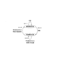
- FIG. 8 is a diagram illustrating an example of state transition between the normal configuration state and the special configuration state according to Embodiment 2 of the present invention.
- the digital object 211 and the like are assumed to be in a normal configuration state and a special configuration state.
- the normal configuration state is a configuration when digital object data is drawn with default settings.
- the special configuration state is a configuration when the display content of the user interface 201 is drawn according to the operation content assumed from the surrounding environment or the operation history. For example, the state transition described below is performed.
- step S41 When the absence of a person is detected (step S41), the control processing unit 69 maintains the normal configuration state. When the presence of a person is detected (step S42), the control processing unit 69 makes a transition to the special configuration state.
- step S43 When the preset time has not elapsed (step S43), the control processing unit 69 maintains the special configuration state. When the preset time has elapsed (step S44), the control processing unit 69 makes a transition to the normal configuration state.
- FIG. 9 is a flowchart for explaining an operation example of the remote controller 31 according to the second embodiment of the present invention.
- processing from step S54 to step S56 is temperature determination processing in which the digital object 211 is displayed according to the surrounding environment.
- the processing from step S58 to step S60 is an operation history determination process in which the digital object 211 is displayed according to the operation history. That is, the operation described with reference to FIG. 9 is processing for displaying the digital object 211 according to the surrounding environment or the operation history. However, for example, the presence / absence determination result of the person and the operating status of the indoor unit 21 are used as a trigger for shifting to processing according to the surrounding environment or the operation history.
- Step S51 The remote controller 31 determines whether or not the current presence / absence determination result is an in-room state. If the current presence / absence determination result is the occupancy state, the remote controller 31 proceeds to step S52. On the other hand, the remote controller 31 returns to step S51, when the present presence determination result is not in an occupancy state.
- Step S52 If the immediately preceding presence / absence determination result is absent, the remote controller 31 proceeds to step S53. On the other hand, if the immediately preceding presence / absence determination result is not absent, the remote controller 31 proceeds to step S61.
- the remote controller 31 obtains the presence / absence determination result of the current person in step S51, and determines the presence / absence state of the person 30 seconds ago as the presence / absence determination result of the immediately preceding person in step S52. It is determined whether it is in a state or is now in the room. Specifically, if the remote controller 31 is currently in the room and is in the room immediately before, the remote controller 31 determines that the room has been in the room for a long time, and does not shift to the operation state determination process of the indoor unit 21.
- the remote controller 31 determines that the room is now, that is, that a person has entered the absent room, and determines the operating state of the indoor unit 21. Transition to processing.
- the time immediately before 30 seconds is an example, and the present invention is not particularly limited to this.
- the immediately preceding time may be 10 seconds before.
- Step S53 The remote controller 31 determines whether or not the indoor unit 21 is operating. When the indoor unit 21 is not operating, the remote controller 31 proceeds to step S54. On the other hand, when the indoor unit 21 is operating, the remote controller 31 proceeds to step S58.
- the state where the indoor unit 21 is not in operation includes not only the state where the power to the indoor unit 21 is cut off but also the state where the indoor unit 21 is on standby for operation.
- the refrigerant stagnation operation may be performed in the indoor unit 21 and the outdoor unit 11.
- the state in which the indoor unit 21 is operating is a state in which a refrigeration cycle is formed in the indoor unit 21 and the outdoor unit 11 by operating the outdoor unit 11 as the indoor unit 21 operates. It is assumed that it means a state where air conditioning is implemented.
- Step S54 The remote controller 31 determines which is the room temperature. When the room temperature is not less than the heating determination temperature and not more than the cooling determination temperature, the remote controller 31 proceeds to step S61. If the room temperature is less than the heating determination temperature, the remote controller 31 proceeds to step S55. If the room temperature is higher than the cooling determination temperature, the remote controller 31 proceeds to step S56.
- Step S55 The remote controller 31 displays the digital object 211 corresponding to the setting content at the start of the heating operation, and proceeds to step S57.
- Step S56 The remote controller 31 displays the digital object 211 corresponding to the setting content at the start of the cooling operation, and proceeds to step S57.
- Step S57 The remote controller 31 determines whether a preset time has elapsed. The remote controller 31 ends the process when a preset time has elapsed. On the other hand, when the preset time has not elapsed, the remote controller 31 returns to step S53.
- the preset time is, for example, 5 minutes, but is not particularly limited thereto.
- the remote controller 31 may shift from the special configuration mode to the normal configuration mode.
- Step S58 The remote controller 31 determines which operation mode is in effect. If the operation mode is other than cooling and heating, the remote controller 31 proceeds to step S61. If the operation mode is heating, the remote controller 31 proceeds to step S59. If the operation mode is cooling, the remote controller 31 proceeds to step S60.
- Step S59 The remote controller 31 displays the digital object 211 corresponding to the setting content during the heating operation, and proceeds to step S57.
- Step S60 The remote controller 31 displays the digital object 211 corresponding to the setting content during the cooling operation, and proceeds to step S57.
- Step S61 The remote controller 31 displays the digital object 211 corresponding to the normal configuration, and proceeds to step S57.
- the digital object 211 is displayed according to the surrounding environment or the operation history at the timing when the person enters the room. Accordingly, since the digital object 211 displayed by the remote controller 31 reflects the immediately preceding state, the remote controller 31 supplies the user with the optimum intuitive user interface 201 according to the usage environment particularly remarkably. be able to.
- the control processing unit 69 performs an operation assumed from the surrounding environment or the operation history.
- the corresponding digital object 211 is displayed.
- control processing unit 69 displays the digital object 211 corresponding to the operation assumed from the surrounding environment, the indoor temperature corresponding to the air-conditioning target space of the indoor unit 21 and the cooling determination temperature are displayed. And the digital object 211 used to start the cooling operation or the heating operation based on the heating determination temperature.
- the control processing unit 69 when displaying the digital object 211 corresponding to the operation assumed from the operation history, the control processing unit 69 is used for setting the operation mode corresponding to the previous operation in the operation history.
- the digital object 211 to be displayed is displayed.
- the optimum and intuitive user interface 201 can be supplied particularly notably according to the use environment.
- Embodiment 3 (Differences from other embodiments) The difference from Embodiment 1 and Embodiment 2 is that an example of the special configuration state is specifically shown.
- the remote controller 31 changes the display size of a digital object 251, a digital object 261, a digital object 271, and a digital object 281 described later.
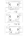
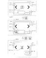
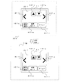
- FIG. 10 is a diagram showing a display example of the digital object 251 in the special configuration state assuming the setting contents at the start of the cooling operation in the third embodiment of the present invention.
- the digital object 251a, the digital object 251b, the digital object 251c, the digital object 251d, and the digital object 251e are displayed on the user interface 201.
- the digital object 251a, the digital object 251b, the digital object 251c, the digital object 251d, and the digital object 251e are referred to as a digital object 251 when they are not particularly distinguished.
- the display size is changed because the size of the digital object 251 corresponding to the surrounding environment is changed. For example, the display size of the digital object 251b is enlarged.
- a transition from the pre-temperature determination state 601 to the post-temperature determination second state 661 is made. In this case, since the size of the digital object 251b is changed in the second state 661 after temperature determination, the display size is changed and enlarged, and at the same time, the button drawn as the digital object 251c is deleted.
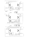
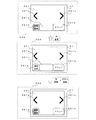
- FIG. 11 is a diagram showing a display example of the digital object 261 in the special configuration state assuming the setting contents at the start of the heating operation in the third embodiment of the present invention.
- the digital object 261a, the digital object 261b, the digital object 261c, the digital object 261d, and the digital object 261e are displayed on the user interface 201.
- the digital object 261a, the digital object 261b, the digital object 261c, the digital object 261d, and the digital object 261e are referred to as a digital object 261 unless particularly distinguished.
- the display size is changed because the size of the digital object 261 corresponding to the surrounding environment is changed. For example, the display size of the digital object 261b is enlarged.
- the state before temperature determination 602 has transitioned to the second state 662 after temperature determination. In this case, since the size of the digital object 261b is changed in the second state 662 after the temperature determination, the display size is changed and enlarged, and at the same time, the button drawn as the digital object 261c is deleted.
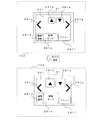
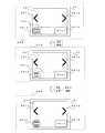
- FIG. 12 is a diagram showing a display example of the digital object 271 in the special configuration state assuming the setting contents during the cooling operation in the third embodiment of the present invention.
- the digital object 271a, the digital object 271b, the digital object 271c, the digital object 271d, the digital object 271e, the digital object 271f, and the digital object 271g are displayed on the user interface 201.
- the digital object 271a, the digital object 271b, the digital object 271c, the digital object 271d, the digital object 271e, the digital object 271f, and the digital object 271g are referred to as a digital object 271 when they are not particularly distinguished.
- the display size is changed because the digital objects 271a, 271b, 271d, and 271e corresponding to the operation history are resized. For example, the display sizes of the digital object 271a, the digital object 271b, the digital object 271d, and the digital object 271e are enlarged.
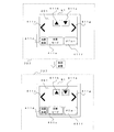
- FIG. 13 is a diagram showing a display example of the digital object 281 in the special configuration state assuming the setting contents during the heating operation in the third embodiment of the present invention.
- the digital object 281a, the digital object 281b, the digital object 281c, the digital object 281d, the digital object 281e, the digital object 281f, and the digital object 281g are displayed on the user interface 201.
- the digital object 281a, the digital object 281b, the digital object 281c, the digital object 281d, the digital object 281e, the digital object 281f, and the digital object 281g are referred to as a digital object 281 unless particularly distinguished.
- the display size is changed because the digital objects 281a, 281b, 281d, and 281e corresponding to the operation history are resized. For example, the display sizes of the digital object 281a, the digital object 281b, the digital object 281d, and the digital object 281e are enlarged.
- the remote controller 31 may draw the unnecessary digital object 251, digital object 261, digital object 271, and digital object 281 so as to be smaller than the normal size.
- the setting contents at the start of the cooling operation are highlighted.
- the digital object 251b is displayed with characters “cooling start / stop”, is a button for starting the cooling operation, and is enlarged. Therefore, the remote controller 31 can provide the optimal and intuitive user interface 201 according to the surrounding environment which is one of the usage environments.
- the setting contents at the start of the heating operation are highlighted.
- the digital object 251b is displayed with characters “heating start / stop”, is a button for starting the heating operation, and is enlarged. Therefore, the remote controller 31 can provide the optimal and intuitive user interface 201 according to the surrounding environment which is one of the usage environments.
- the setting contents during the cooling operation are highlighted.
- the digital object 271a is a lower triangle button, and supplies a control command for lowering the set temperature to the control processing unit 69 when an operation such as pressing is performed. Since the digital object 271a is enlarged and displayed, it is highlighted.
- the digital object 271b is an upper triangle button, and supplies a control command for increasing the set temperature to the control processing unit 69 when an operation such as pressing is performed. The digital object 271b is highlighted because it is enlarged.
- the digital object 271d is displayed with characters “cooling start / stop”, is a button for stopping the cooling operation, and is enlarged.
- the digital object 271e has characters “COOLING MODE” displayed thereon, serves as a button for changing to the setting of the COOLING mode, and is enlarged. Therefore, the remote controller 31 can provide the optimum intuitive user interface 201 according to the operation history that is one of the usage environments.
- the setting contents during the heating operation are highlighted.
- the digital object 281a is a lower triangle button, and supplies a control command for lowering the set temperature to the control processing unit 69 when an operation such as pressing is performed. Since the digital object 281a is enlarged and displayed, it is highlighted.
- the digital object 281b is an upper triangle button, and supplies a control command for raising the set temperature to the control processing unit 69 when an operation such as pressing is performed. Since the digital object 281b is enlarged and displayed, it is highlighted.
- the digital object 281d is displayed with the characters “heating start / stop”, is a button for stopping the heating operation, and is enlarged.
- the digital object 281e is displayed with characters “heating mode”, is a button for transitioning to the setting of the heating mode, and is enlarged. Therefore, the remote controller 31 can provide the optimum intuitive user interface 201 according to the operation history that is one of the usage environments.
- the remote controller 31 according to the third embodiment can provide the optimal and intuitive user interface 201 particularly remarkably according to the use environment.
- control processing unit 69 changes the display size of the digital objects 251, 261, 271, and 281.
- the display size of the digital objects 251 and 261 corresponding to the surrounding environment is set as follows. The display size of the digital objects 251 and 261 not corresponding to the surrounding environment is increased.
- the display size of the digital objects 271 and 281 corresponding to the operation history is set as follows. The display size of the digital objects 271 and 281 that do not correspond to the operation history is increased.
- the optimum and intuitive user interface 201 can be supplied particularly notably according to the use environment.
- Embodiment 4 (Differences from other embodiments) The difference from the first to third embodiments is that an example of the special configuration state is specifically shown.
- the remote controller 31 changes the display positions of a digital object 291, a digital object 311, a digital object 321, and a digital object 331, which will be described later.
- FIG. 14 is a diagram showing a display example of the digital object 291 in the special configuration state assuming the setting contents at the start of the cooling operation in the fourth embodiment of the present invention.
- the digital object 291a, the digital object 291b, the digital object 291c, the digital object 291d, and the digital object 291e are displayed on the user interface 201.
- the digital object 291a, the digital object 291b, the digital object 291c, the digital object 291d, and the digital object 291e are referred to as a digital object 291 unless particularly distinguished.
- the control processing unit 69 displays the display position of the digital object 291b on the center side of the display screen as the user interface 201 so that the digital object 291b corresponding to the surrounding environment is easily operated.
- the control processing unit 69 may display the display position of the digital object 291d or the like on the edge of the display screen as the user interface 201 so that the digital object 291d or the like that does not correspond to the surrounding environment is difficult to operate. .
- FIG. 15 is a diagram showing a display example of the digital object 311 in the special configuration state assuming the setting contents at the start of the heating operation in the fourth embodiment of the present invention.
- the digital object 311a, the digital object 311b, the digital object 311c, the digital object 311d, and the digital object 311e are displayed on the user interface 201.
- the digital object 311a, the digital object 311b, the digital object 311c, the digital object 311d, and the digital object 311e are referred to as a digital object 311 unless particularly distinguished.
- the control processing unit 69 displays the display position of the digital object 311b on the center side of the display screen that is the user interface 201 so that the digital object 311b corresponding to the surrounding environment is easily operated.
- the control processing unit 69 may display the display position of the digital object 311d or the like on the edge side of the display screen that is the user interface 201 so that the digital object 311d or the like that does not correspond to the surrounding environment is difficult to operate. .
- FIG. 16 is a diagram showing a display example of the digital object 321 in the special configuration state assuming the setting contents during the refrigeration operation in the fourth embodiment of the present invention.
- FIG. 16 is a diagram showing a display example of the digital object 321 in the special configuration state assuming the setting contents during the cooling operation in Embodiment 4 of the present invention.
- the digital object 321a, the digital object 321b, the digital object 321c, the digital object 321d, the digital object 321e, the digital object 321f, and the digital object 321g are displayed on the user interface 201. ing.
- the digital object 321a, the digital object 321b, the digital object 321c, the digital object 321d, the digital object 321e, the digital object 321f, and the digital object 321g are referred to as a digital object 321 unless particularly distinguished.
- the display position is changed because the positions of the digital object 321a, the digital object 321b, the digital object 321d, and the digital object 321e corresponding to the operation history are changed.
- the control processing unit 69 sets the digital object 321a, the digital object 321b, and the digital object 321d so that the digital object 321a, the digital object 321b, the digital object 321d, and the digital object 321e corresponding to the operation history are easily operated.
- the display position of the digital object 321e is displayed on the center side of the display screen which is the user interface 201.
- the control processing unit 69 may display the display position of the digital object 321f or the like on the edge of the display screen that is the user interface 201 so that the digital object 321f or the like that does not correspond to the operation history is in a position that is difficult to operate. .
- FIG. 17 is a diagram illustrating a display example of the digital object 331 in the special configuration state assuming the setting contents during the heating operation according to the fourth embodiment of the present invention.
- FIG. 17 is a diagram illustrating a display example of the digital object 331 in the special configuration state assuming the setting contents during the heating operation according to the fourth embodiment of the present invention.
- the digital object 331a, the digital object 331b, the digital object 331c, the digital object 331d, the digital object 331e, the digital object 331f, and the digital object 331g are displayed on the user interface 201. ing.
- digital object 331a the digital object 331b, the digital object 331c, the digital object 331d, the digital object 331e, the digital object 331f, and the digital object 331g are referred to as a digital object 331 unless particularly distinguished.
- the display position is changed because the positions of the digital object 331a, the digital object 331b, the digital object 331d, and the digital object 331e corresponding to the operation history are changed.
- the control processing unit 69 sets the digital object 331a, the digital object 331b, and the digital object 331d so that the digital object 331a, the digital object 331b, the digital object 331d, and the digital object 331e corresponding to the operation history are easily operated.
- the display position of the digital object 331e is displayed on the center side of the display screen which is the user interface 201.
- control processing unit 69 may display the display position of the digital object 331f or the like on the edge of the display screen that is the user interface 201 so that the digital object 331f or the like that does not correspond to the operation history becomes a difficult position to operate. .
- the setting contents at the start of the cooling operation are highlighted.
- the digital object 291b is displayed with characters “cooling start / stop”, serves as a button for starting the cooling operation, and is displayed on the center side of the display screen. Therefore, the remote controller 31 can provide the optimal and intuitive user interface 201 according to the surrounding environment which is one of the usage environments.
- the setting contents at the start of the heating operation are highlighted.
- the digital object 311b is displayed with the characters “heating start / stop”, is a button for starting the heating operation, and is displayed on the center side of the display screen. Therefore, the remote controller 31 can provide the optimal and intuitive user interface 201 according to the surrounding environment which is one of the usage environments.
- the setting contents during the cooling operation are highlighted.
- the digital object 321a is a lower triangle button, and supplies a control command for lowering the set temperature to the control processing unit 69 when an operation such as pressing is performed. Since the digital object 321a is displayed on the center side of the display screen, it is highlighted.
- the digital object 321b is an upper triangle button, and supplies a control command for increasing the set temperature to the control processing unit 69 when an operation such as pressing is performed. Since the digital object 321b is displayed on the center side of the display screen, it is highlighted.
- the digital object 321d is displayed with characters “cooling start / stop”, is a button for stopping the cooling operation, and is displayed on the center side of the display screen.
- the digital object 321e is displayed with characters “COOLING MODE”, is a button for shifting to the setting of the cooling mode, and is displayed on the center side of the display screen. Therefore, the remote controller 31 can provide the optimum intuitive user interface 201 according to the operation history that is one of the usage environments.
- the setting contents during the heating operation are highlighted.
- the digital object 331a is a lower triangle button, and supplies a control command for lowering the set temperature to the control processing unit 69 when an operation such as pressing is performed. Since the digital object 331a is displayed on the center side of the display screen, it is highlighted.
- the digital object 331b is an upper triangle button, and supplies a control command for raising the set temperature to the control processing unit 69 when an operation such as pressing is performed. Since the digital object 331b is displayed on the center side of the display screen, it is highlighted.
- the digital object 331d is displayed with the letters “heating start / stop”, is a button for stopping the heating operation, and is displayed on the center side of the display screen.
- the digital object 331e is displayed with characters “heating mode”, is a button for changing to the setting of the heating mode, and is displayed on the center side of the display screen. Therefore, the remote controller 31 can provide the optimum intuitive user interface 201 according to the operation history that is one of the usage environments.
- the remote controller 31 according to the fourth embodiment can provide the optimum and intuitive user interface 201 according to the usage environment, particularly notably.
- control processing unit 69 changes the display position of the digital objects 291, 311, 321 and 331.
- the control processing unit 69 displays the digital objects 291 and 311 on the display screen to be output to the display unit 63, and the digital object 291 corresponding to the operation assumed from the surrounding environment. 311 is displayed, the display positions of the digital objects 291 and 311 corresponding to the surrounding environment are displayed on the center side of the display screen, and the display positions of the digital objects 291 and 311 not corresponding to the surrounding environment are displayed on the edge side of the display screen.
- the control processing unit 69 displays the digital objects 321 and 331 on the display screen to be output to the display unit 63, and the digital object 321 corresponding to the operation assumed from the operation history. 331, the display position of the digital objects 321 and 331 corresponding to the operation history is displayed on the center side of the display screen, and the display position of the digital objects 321 and 331 not corresponding to the operation history is displayed on the edge side of the display screen.
- the optimum and intuitive user interface 201 can be supplied particularly notably according to the use environment.
- Embodiment 5 (Differences from other embodiments) The difference from the first to fourth embodiments is that an example of the special configuration state is specifically shown.
- the remote controller 31 changes display colors of a digital object 341, a digital object 351, a digital object 361, and a digital object 371, which will be described later.
- FIG. 18 is a diagram illustrating a display example of the digital object 341 in the special configuration state assuming the setting content at the start of the cooling operation according to the fifth embodiment of the present invention.
- the digital object 341a, the digital object 341b, the digital object 341c, the digital object 341d, and the digital object 341e are displayed on the user interface 201.
- the digital object 341a, the digital object 341b, the digital object 341c, the digital object 341d, and the digital object 341e are referred to as a digital object 341 when they are not particularly distinguished.
- the control processing unit 69 sets the brightness or saturation of the display color of the digital object 341b so that the digital object 341b corresponding to the surrounding environment stands out, the digital object 341a, the digital object 341c, and the digital object 341d not corresponding to the surrounding environment. , And the brightness or saturation of the display color of the digital object 341e.
- FIG. 19 is a diagram showing a display example of the digital object 351 in the special configuration state assuming the setting contents at the start of the heating operation in the fifth embodiment of the present invention.
- the digital object 351a, the digital object 351b, the digital object 351c, the digital object 351d, and the digital object 351e are displayed on the user interface 201.
- each of the digital object 351a, the digital object 351b, the digital object 351c, the digital object 351d, and the digital object 351e is referred to as a digital object 351 unless particularly distinguished.
- the control processing unit 69 sets the brightness or saturation of the display color of the digital object 351b so that the digital object 351b corresponding to the surrounding environment is conspicuous, the digital object 351a, the digital object 351c, and the digital object 351d not corresponding to the surrounding environment. And the brightness or saturation of the display color of the digital object 351e.
- FIG. 20 is a diagram illustrating a display example of the digital object 361 in the special configuration state assuming the setting contents during the cooling operation according to the fifth embodiment of the present invention.
- FIG. 20 is a diagram illustrating a display example of the digital object 361 in the special configuration state assuming the setting content during the cooling operation according to the fifth embodiment of the present invention.
- the digital object 361a, the digital object 361b, the digital object 361c, the digital object 361d, the digital object 361e, the digital object 361f, and the digital object 361g are displayed on the user interface 201. ing.
- digital object 361a the digital object 361b, the digital object 361c, the digital object 361d, the digital object 361e, the digital object 361f, and the digital object 361g are referred to as a digital object 361 unless particularly distinguished.
- the control processing unit 69 makes the digital object 361a, the digital object 361b, the digital object 361d, and the digital object 361e so that the digital object 361a, the digital object 361b, the digital object 361d, and the digital object 361e corresponding to the operation history stand out. Is made higher than the brightness or saturation of the display colors of the digital object 361c, the digital object 361f, and the digital object 361g that do not correspond to the surrounding environment.
- FIG. 21 is a diagram showing a display example of the digital object 371 in the special configuration state assuming the setting contents during the heating operation in the fifth embodiment of the present invention.
- FIG. 21 is a diagram illustrating a display example of the digital object 371 in a special configuration state assuming the setting contents during the heating operation according to the fifth embodiment of the present invention.
- the digital object 371a, the digital object 371b, the digital object 371c, the digital object 371d, the digital object 371e, the digital object 371f, and the digital object 371g are displayed on the user interface 201. ing.
- the digital object 371a, the digital object 371b, the digital object 371c, the digital object 371d, the digital object 371e, the digital object 371f, and the digital object 371g are referred to as a digital object 371 unless particularly distinguished.
- the control processing unit 69 makes the digital object 371a, the digital object 371b, the digital object 371d, and the digital object 371e so that the digital object 371a, the digital object 371b, the digital object 371d, and the digital object 371e corresponding to the operation history stand out. Is made higher than the brightness or saturation of the display colors of the digital object 371c, the digital object 371f, and the digital object 371g that do not correspond to the surrounding environment.
- the remote controller 31 can provide the optimal and intuitive user interface 201 according to the surrounding environment which is one of the usage environments.
- the setting contents at the start of the heating operation are highlighted.
- the digital object 351b is displayed with the letters “heating start / stop”, serves as a button for starting the heating operation, and other digital objects 351 that do not correspond to the surrounding environment in terms of brightness or saturation of the display color. Higher than that. Therefore, the remote controller 31 can provide the optimal and intuitive user interface 201 according to the surrounding environment which is one of the usage environments.
- the setting contents during the cooling operation are highlighted.
- the digital object 361 a is a lower triangle button, and supplies a control command for lowering the set temperature to the control processing unit 69 when an operation such as pressing is performed.
- the digital object 361a is highlighted because the brightness or saturation of the display color is higher than that of other digital objects 361 that do not correspond to the operation history.
- the digital object 361b is an upper triangle button, and supplies a control command for raising the set temperature to the control processing unit 69 when an operation such as pressing is performed.
- the digital object 361b is highlighted because the brightness or saturation of the display color is higher than that of other digital objects 361 that do not correspond to the operation history.
- the digital object 361d is displayed with the characters “cooling start / stop”, serves as a button for stopping the cooling operation, and the brightness or saturation of the display color does not correspond to the operation history. Since it is made higher than the object 361, it is highlighted.
- the digital object 361e is a button that displays the characters “cooling mode” and makes a transition to the setting of the cooling mode, and compares the brightness or saturation of the display color with other digital objects 361 that do not correspond to the operation history. So it is highlighted. Therefore, the remote controller 31 can provide the optimum intuitive user interface 201 according to the operation history that is one of the usage environments.
- the setting contents during the heating operation are highlighted.
- the digital object 371a is a lower triangle button, and supplies a control command for lowering the set temperature to the control processing unit 69 when an operation such as pressing is performed.
- the digital object 371a is highlighted because the brightness or saturation of the display color is higher than that of other digital objects 371 that do not correspond to the operation history.
- the digital object 371b is an upper triangle button, and supplies a control command for increasing the set temperature to the control processing unit 69 when an operation such as pressing is performed.
- the digital object 371b is highlighted because the brightness or saturation of the display color is higher than that of other digital objects 371 that do not correspond to the operation history.
- the digital object 371d is displayed with the characters “heating on / off” and serves as a button for stopping the heating operation, and the lightness or saturation of the display color does not correspond to the operation history. Since it is made higher than the object 371, it is highlighted.
- the digital object 371e is displayed with the characters “heating mode” and is a button for transitioning to the setting of the heating mode, and the brightness or saturation of the display color is compared with other digital objects 371 that do not correspond to the operation history. So it is highlighted. Therefore, the remote controller 31 can provide the optimum intuitive user interface 201 according to the operation history that is one of the usage environments.
- the remote controller 31 can supply the optimal and intuitive user interface 201 particularly notably according to the use environment.
- control processing unit 69 changes the display color of the digital objects 341, 351, 361, and 371.
- the control processing unit 69 displays the digital objects 341 and 351 corresponding to the operation assumed from the surrounding environment
- the brightness of the display color of the digital objects 341 and 351 corresponding to the surrounding environment is set higher than the brightness or saturation of the display color of the digital objects 341 and 351 that do not correspond to the surrounding environment.
- the control processing unit 69 displays the digital objects 361 and 371 corresponding to the operation assumed from the operation history
- the brightness of the display color of the digital objects 361 and 371 corresponding to the operation history is made higher than the brightness or saturation of the display color of the digital objects 361 and 371 that do not correspond to the operation history.
- the optimum and intuitive user interface 201 can be supplied particularly notably according to the use environment.
- Embodiment 6 (Differences from other embodiments) The difference from Embodiments 1 to 5 is that an example of the special configuration state is specifically shown.
- the remote controller 31 changes the display shapes of a digital object 381, a digital object 391, a digital object 411, and a digital object 421, which will be described later.
- FIG. 22 is a diagram illustrating a display example of the digital object 381 in the special configuration state assuming the setting contents at the start of the cooling operation according to the sixth embodiment of the present invention.
- the digital object 381a, the digital object 381b, the digital object 381c, the digital object 381d, and the digital object 381e are displayed on the user interface 201.
- the digital object 381a, the digital object 381b, the digital object 381c, the digital object 381d, and the digital object 381e are referred to as a digital object 381 unless particularly distinguished.
- the control processing unit 69 displays the display shape of the digital object 381b based on the highlight image information so that the digital object 381b corresponding to the surrounding environment is conspicuous.
- FIG. 23 is a diagram showing a display example of the digital object 391 in the special configuration state assuming the setting contents at the start of the heating operation in the sixth embodiment of the present invention.
- the digital object 391a, the digital object 391b, the digital object 391c, the digital object 391d, and the digital object 391e are displayed on the user interface 201.
- the digital object 391a, the digital object 391b, the digital object 391c, the digital object 391d, and the digital object 391e are referred to as a digital object 391 unless particularly distinguished.
- the control processing unit 69 displays the display shape of the digital object 391b based on the highlight image information so that the digital object 391b corresponding to the surrounding environment is conspicuous.
- FIG. 24 is a diagram showing a display example of the digital object 411 in the special configuration state assuming the setting contents at the time of cooling operation in the sixth embodiment of the present invention.
- the digital object 411a, the digital object 411b, the digital object 411c, the digital object 411d, the digital object 411e, the digital object 411f, and the digital object 411g are displayed on the user interface 201. ing.
- digital object 411a the digital object 411b, the digital object 411c, the digital object 411d, the digital object 411e, the digital object 411f, and the digital object 411g are referred to as a digital object 411 unless particularly distinguished.
- the control processing unit 69 makes the digital object 361a, the digital object 361b, the digital object 361d, and the digital object 361e so that the digital object 361a, the digital object 361b, the digital object 361d, and the digital object 361e corresponding to the operation history stand out. Is displayed based on the highlight display image information.
- FIG. 25 is a diagram showing a display example of the digital object 421 in the special configuration state assuming the setting contents during the heating operation in the sixth embodiment of the present invention.
- the digital object 421a, the digital object 421b, the digital object 421c, the digital object 421d, the digital object 421e, the digital object 421f, and the digital object 421g are displayed on the user interface 201. ing.
- digital object 421a, the digital object 421b, the digital object 421c, the digital object 421d, the digital object 421e, the digital object 421f, and the digital object 421g are referred to as a digital object 421 unless particularly distinguished.
- the display shape is changed because the digital object 421a, the digital object 421b, the digital object 421d, and the digital object 421e corresponding to the operation history are changed in shape.
- the control processing unit 69 makes the digital object 421a, the digital object 421b, the digital object 421d, and the digital object 421e so that the digital object 421a, the digital object 421b, the digital object 421d, and the digital object 421e corresponding to the operation history stand out. Is displayed based on the highlight display image information.
- the remote controller 31 As described above, in the remote controller 31 according to the sixth embodiment, as shown in FIG. 22, the setting contents at the start of the cooling operation are highlighted. For example, the digital object 381b is displayed with characters “cooling start / stop”, serves as a button for starting the cooling operation, and displays the display shape based on the highlighted image information. Therefore, the remote controller 31 can provide the optimal and intuitive user interface 201 according to the surrounding environment which is one of the usage environments.
- the setting contents at the start of the heating operation are highlighted.
- the digital object 391b is displayed with characters “heating start / stop”, serves as a button for starting the heating operation, and displays the display shape based on the highlight image information. Therefore, the remote controller 31 can provide the optimal and intuitive user interface 201 according to the surrounding environment which is one of the usage environments.
- the setting contents during the cooling operation are highlighted.
- the digital object 411 a is a lower triangle button, and supplies a control command for lowering the set temperature to the control processing unit 69 when an operation such as pressing is performed.
- the digital object 411a is highlighted because the display shape is displayed based on the highlight image information.
- the digital object 361b is an upper triangle button, and supplies a control command for raising the set temperature to the control processing unit 69 when an operation such as pressing is performed.
- the digital object 361b is highlighted because the display shape is displayed based on the highlight image information.
- the digital object 411d is displayed with the characters “cooling start / stop”, is a button for stopping the cooling operation, and the display shape is displayed based on the highlight image information. Is highlighted.
- the digital object 411e is displayed with the characters “COOLING MODE”, is a button for transitioning to the setting of the COOLING MODE, and the display shape is displayed based on the highlighting image information. Yes. Therefore, the remote controller 31 can provide the optimum intuitive user interface 201 according to the operation history that is one of the usage environments.
- the setting contents during heating operation are highlighted.
- the digital object 421a is a lower triangle button, and supplies a control command for lowering the set temperature to the control processing unit 69 when an operation such as pressing is performed. Since the display shape of the digital object 421a is displayed based on the highlight display image information, the digital object 421a is highlighted.
- the digital object 421b is an upper triangle button, and supplies a control command for raising the set temperature to the control processing unit 69 when an operation such as pressing is performed. Since the display shape of the digital object 421b is displayed based on the highlight display image information, the digital object 421b is highlighted.
- the digital object 421d is displayed with the characters “heating start / stop”, is a button for stopping the heating operation, and the display shape is displayed based on the highlight image information. Is highlighted.
- the digital object 421e is displayed with the letters “heating mode”, is a button for transitioning to the setting of the heating mode, and the display shape is displayed based on the image information for highlighting. Yes. Therefore, the remote controller 31 can provide the optimum intuitive user interface 201 according to the operation history that is one of the usage environments.
- the remote controller 31 can supply the optimal and intuitive user interface 201 particularly notably according to the use environment.
- control processing unit 69 changes the display shape of the digital objects 381, 391, 411, 421.
- the storage unit 65 includes highlight display image information corresponding to the digital objects 381 and 391 and normal display image information corresponding to the digital objects 381 and 391, respectively.
- the control processing unit 69 displays the digital objects 381 and 391 corresponding to the operation assumed from the surrounding environment
- the display shape of the digital objects 381 and 391 corresponding to the surrounding environment is displayed based on the highlight image information.
- the display shapes of the digital objects 381 and 391 not corresponding to the surrounding environment are displayed based on the normal display image information.
- the storage unit 65 includes highlight display image information corresponding to the digital objects 411 and 421, and normal display image information corresponding to the digital objects 411 and 421, respectively.
- the control processing unit 69 displays the digital objects 411 and 421 corresponding to the operation assumed from the operation history
- the display shape of the digital objects 411 and 421 corresponding to the operation history is displayed based on the highlight image information.
- the display shapes of the digital objects 411 and 421 that do not correspond to the operation history are displayed based on the normal display image information.
- the optimum and intuitive user interface 201 can be supplied particularly notably according to the use environment.
Landscapes
- Engineering & Computer Science (AREA)
- Chemical & Material Sciences (AREA)
- Combustion & Propulsion (AREA)
- Mechanical Engineering (AREA)
- General Engineering & Computer Science (AREA)
- Signal Processing (AREA)
- Physics & Mathematics (AREA)
- Fuzzy Systems (AREA)
- Mathematical Physics (AREA)
- Human Computer Interaction (AREA)
- Air Conditioning Control Device (AREA)
- Selective Calling Equipment (AREA)
Abstract
Description
(実施の形態1の構成)
図1は、本発明の実施の形態1における空気調和システム1の概略構成の一例を示す図である。図1において、本発明の実施の形態1は、周囲環境又は操作履歴から想定される操作内容に応じて、後述するユーザインターフェース201の表示内容を構成することで、使用環境に応じて、最適で直感的なユーザインターフェース201を供給する。以下、その詳細について説明する。
次に、リモートコントローラー31の表示部63で表示されるデジタルオブジェクト211等の構成状態の遷移について説明する。図4は、本発明の実施の形態1における通常構成状態と特殊構成状態との間の状態遷移の一例を示す図である。図4に示すように、デジタルオブジェクト211等は、通常構成状態と、特殊構成状態と、が想定されている。通常構成状態は、デフォルト設定でデジタルオブジェクトデータが描画された場合の構成である。特殊構成状態は、周囲環境又は操作履歴から想定される操作内容に応じて、ユーザインターフェース201の表示内容が描画された場合の構成である。例えば、次に説明する状態遷移が行われる。
制御処理部69は、特殊構成モード指令が無い場合(ステップS11)、通常構成状態を維持させる。制御処理部69は、特殊構成モード指令が有る場合(ステップS12)、特殊構成状態に遷移させる。
制御処理部69は、予め設定された時間が未経過である場合(ステップS13)、特殊構成状態を維持させる。また、制御処理部69は、特殊構成表示指令が有る場合(ステップS13)、特殊構成状態を維持させる。制御処理部69は、予め設定された時間が経過済みである場合(ステップS14)、通常構成状態に遷移させる。また、制御処理部69は、特殊構成表示指令が無い場合(ステップS14)、通常構成状態に遷移させる。
リモートコントローラー31は、特殊構成モード指令が有るか否かを判定する。リモートコントローラー31は、特殊構成モード指令が有る場合、ステップS22に進む。一方、リモートコントローラー31は、特殊構成モード指令が無い場合、ステップS21に戻る。
リモートコントローラー31は、室内ユニット21が稼働しているか否かを判定する。リモートコントローラー31は、室内ユニット21が稼働していない場合、ステップS23に進む。一方、リモートコントローラー31は、室内ユニット21が稼働している場合、ステップS27に進む。
リモートコントローラー31は、室内温度が何れであるかを判定する。リモートコントローラー31は、室内温度が暖房判定温度以上冷房判定温度以下である場合、ステップS30に進む。リモートコントローラー31は、室内温度が暖房判定温度未満である場合、ステップS24に進む。リモートコントローラー31は、室内温度が冷房判定温度と比べて大きい場合、ステップS25に進む。
リモートコントローラー31は、暖房運転開始時の設定内容に対応するデジタルオブジェクト211を表示し、ステップS26に移行する。
リモートコントローラー31は、冷房運転開始時の設定内容に対応するデジタルオブジェクト211を表示し、ステップS26に移行する。
リモートコントローラー31は、予め設定された時間が経過したか否かを判定する。リモートコントローラー31は、予め設定された時間が経過した場合、処理を終了する。一方、リモートコントローラー31は、予め設定された時間が経過しない場合、ステップS22に戻る。なお、ここで、予め設定された時間とは、例えば、5分間であるが、特にこれに限定されない。つまり、ユーザがリモートコントローラー31を使用すると想定される時間が経過した場合、リモートコントローラー31は、特殊構成モードから通常構成モードに移行すればよい。
リモートコントローラー31は、運転モードが何れであるかを判定する。リモートコントローラー31は、運転モードが冷房かつ暖房以外である場合、ステップS30に進む。リモートコントローラー31は、運転モードが暖房である場合、ステップS28に進む。リモートコントローラー31は、運転モードが冷房である場合、ステップS29に進む。
リモートコントローラー31は、暖房運転時の設定内容に対応するデジタルオブジェクト211を表示し、ステップS26に移行する。
リモートコントローラー31は、冷房運転時の設定内容に対応するデジタルオブジェクト211を表示し、ステップS26に移行する。
リモートコントローラー31は、通常構成に対応するデジタルオブジェクト211を表示し、ステップS26に移行する。
以上の説明から、リモートコントローラー31は、室内ユニット21が稼働していない場合、室内温度等の周囲環境を判定し、判定結果から想定される操作内容に応じて、ユーザインターフェース201の表示内容を構成する。また、リモートコントローラー31は、室内ユニット21が稼働している場合、運転モード等の操作履歴を判定し、判定結果から想定される操作内容に応じて、ユーザインターフェース201の表示内容を構成する。したがって、周囲環境又は操作履歴から想定される操作内容に応じて、ユーザインターフェース201の表示内容を構成することで、使用環境に応じて、最適で直感的なユーザインターフェース201を供給することができる。
(他の実施の形態との相違点)
実施の形態1との相違点は、室内ユニット21の稼働状態の判定処理の前工程の処理が、人の存否判定結果に基づいた動作である点にある。図8は、本発明の実施の形態2における通常構成状態と特殊構成状態との間の状態遷移の一例を示す図である。
図8に示すように、デジタルオブジェクト211等は、通常構成状態と、特殊構成状態と、が想定されている。通常構成状態は、デフォルト設定でデジタルオブジェクトデータが描画された場合の構成である。特殊構成状態は、周囲環境又は操作履歴から想定される操作内容に応じて、ユーザインターフェース201の表示内容が描画された場合の構成である。例えば、次に説明する状態遷移が行われる。
制御処理部69は、人の不在が検知された場合(ステップS41)、通常構成状態を維持させる。制御処理部69は、人の在室が検知された場合(ステップS42)、特殊構成状態に遷移させる。
制御処理部69は、予め設定された時間が未経過である場合(ステップS43)、特殊構成状態を維持させる。制御処理部69は、予め設定された時間が経過済みである場合(ステップS44)、通常構成状態に遷移させる。
リモートコントローラー31は、現在の存否判定結果が在室状態であるか否かを判定する。リモートコントローラー31は、現在の存否判定結果が在室状態である場合、ステップS52に進む。一方、リモートコントローラー31は、現在の存否判定結果が在室状態でない場合、ステップS51に戻る。
リモートコントローラー31は、直前の存否判定結果が不在状態である場合、ステップS53に進む。一方、リモートコントローラー31は、直前の存否判定結果が不在状態でない場合、ステップS61に進む。
リモートコントローラー31は、室内ユニット21が稼働しているか否かを判定する。リモートコントローラー31は、室内ユニット21が稼働していない場合、ステップS54に進む。一方、リモートコントローラー31は、室内ユニット21が稼働している場合、ステップS58に進む。
リモートコントローラー31は、室内温度が何れであるかを判定する。リモートコントローラー31は、室内温度が暖房判定温度以上冷房判定温度以下である場合、ステップS61に進む。リモートコントローラー31は、室内温度が暖房判定温度未満である場合、ステップS55に進む。リモートコントローラー31は、室内温度が冷房判定温度と比べて大きい場合、ステップS56に進む。
リモートコントローラー31は、暖房運転開始時の設定内容に対応するデジタルオブジェクト211を表示し、ステップS57に移行する。
リモートコントローラー31は、冷房運転開始時の設定内容に対応するデジタルオブジェクト211を表示し、ステップS57に移行する。
リモートコントローラー31は、予め設定された時間が経過したか否かを判定する。リモートコントローラー31は、予め設定された時間が経過した場合、処理を終了する。一方、リモートコントローラー31は、予め設定された時間が経過しない場合、ステップS53に戻る。
リモートコントローラー31は、運転モードが何れであるかを判定する。リモートコントローラー31は、運転モードが冷房かつ暖房以外である場合、ステップS61に進む。リモートコントローラー31は、運転モードが暖房である場合、ステップS59に進む。リモートコントローラー31は、運転モードが冷房である場合、ステップS60に進む。
リモートコントローラー31は、暖房運転時の設定内容に対応するデジタルオブジェクト211を表示し、ステップS57に移行する。
リモートコントローラー31は、冷房運転時の設定内容に対応するデジタルオブジェクト211を表示し、ステップS57に移行する。
リモートコントローラー31は、通常構成に対応するデジタルオブジェクト211を表示し、ステップS57に移行する。
以上の説明から、本実施の形態2においては、空調対象空間となっている部屋における人の存否状態が、人の不在状態から人の在室状態へ遷移した場合、温度判定処理又は操作履歴判定処理が実施される。よって、長時間にわたって人が部屋に存在していると想定される場合、温度判定処理又は操作履歴判定処理が実施されることがない。一方、空調対象空間となっている部屋における人の存否状態が、人の不在状態から人の在室状態へ遷移した場合、温度判定処理又は操作履歴判定処理の何れかを選択するために、室内ユニット21の稼働状態が判定される。よって、人が部屋に入室したタイミングで周囲環境又は操作履歴に応じて、デジタルオブジェクト211が表示される。したがって、リモートコントローラー31が表示するデジタルオブジェクト211は直前の状態が反映されているため、リモートコントローラー31は、特に顕著に、使用環境に応じて、最適で直感的なユーザインターフェース201をユーザに供給することができる。
(他の実施の形態との相違点)
実施の形態1及び実施の形態2との相違点は、特殊構成状態の一例を具体的に示した点にある。実施の形態3では、リモートコントローラー31は、後述するデジタルオブジェクト251、デジタルオブジェクト261、デジタルオブジェクト271、及びデジタルオブジェクト281の表示サイズを変更させている。
図10は、本発明の実施の形態3における冷房運転開始時の設定内容を想定した特殊構成状態の場合のデジタルオブジェクト251の表示例を示す図である。図10に示すように、温度判定前状態601では、デジタルオブジェクト251a、デジタルオブジェクト251b、デジタルオブジェクト251c、デジタルオブジェクト251d、及びデジタルオブジェクト251eがユーザインターフェース201に表示されている。なお、デジタルオブジェクト251a、デジタルオブジェクト251b、デジタルオブジェクト251c、デジタルオブジェクト251d、及びデジタルオブジェクト251eのそれぞれを特に区別しない場合、デジタルオブジェクト251と称する。
以上の説明から、本実施の形態3においては、図10に示すように、冷房運転開始時の設定内容が強調表示されている。例えば、デジタルオブジェクト251bは、“冷房発停”という文字が表示され、冷房の運転を開始させるボタンとなっていると共に、拡大表示されている。よって、リモートコントローラー31は、使用環境の1つである周囲環境に応じて、最適で直感的なユーザインターフェース201を提供することができる。
(他の実施の形態との相違点)
実施の形態1~実施の形態3との相違点は、特殊構成状態の一例を具体的に示した点にある。実施の形態4では、リモートコントローラー31は、後述するデジタルオブジェクト291、デジタルオブジェクト311、デジタルオブジェクト321、及びデジタルオブジェクト331の表示位置を変更させている。
図14は、本発明の実施の形態4における冷房運転開始時の設定内容を想定した特殊構成状態の場合のデジタルオブジェクト291の表示例を示す図である。図14に示すように、温度判定前状態603では、デジタルオブジェクト291a、デジタルオブジェクト291b、デジタルオブジェクト291c、デジタルオブジェクト291d、及びデジタルオブジェクト291eがユーザインターフェース201に表示されている。なお、デジタルオブジェクト291a、デジタルオブジェクト291b、デジタルオブジェクト291c、デジタルオブジェクト291d、及びデジタルオブジェクト291eのそれぞれを特に区別しない場合、デジタルオブジェクト291と称する。
以上の説明から、本実施の形態4においては、図14に示すように、冷房運転開始時の設定内容が強調表示されている。例えば、デジタルオブジェクト291bは、“冷房発停”という文字が表示され、冷房の運転を開始させるボタンとなっていると共に、表示画面の中央側に表示されている。よって、リモートコントローラー31は、使用環境の1つである周囲環境に応じて、最適で直感的なユーザインターフェース201を提供することができる。
(他の実施の形態との相違点)
実施の形態1~実施の形態4との相違点は、特殊構成状態の一例を具体的に示した点にある。実施の形態5では、リモートコントローラー31は、後述するデジタルオブジェクト341、デジタルオブジェクト351、デジタルオブジェクト361、及びデジタルオブジェクト371の表示色を変更させている。
図18は、本発明の実施の形態5における冷房運転開始時の設定内容を想定した特殊構成状態の場合のデジタルオブジェクト341の表示例を示す図である。図18に示すように、温度判定前状態605では、デジタルオブジェクト341a、デジタルオブジェクト341b、デジタルオブジェクト341c、デジタルオブジェクト341d、及びデジタルオブジェクト341eがユーザインターフェース201に表示されている。なお、デジタルオブジェクト341a、デジタルオブジェクト341b、デジタルオブジェクト341c、デジタルオブジェクト341d、及びデジタルオブジェクト341eのそれぞれを特に区別しない場合、デジタルオブジェクト341と称する。
以上の説明から、本実施の形態5におけるリモートコントローラー31は、図18に示すように、冷房運転開始時の設定内容が強調表示されている。例えば、デジタルオブジェクト341bは、“冷房発停”という文字が表示され、冷房の運転を開始させるボタンとなっていると共に、表示色の明度又は彩度を、周囲環境に対応しない他のデジタルオブジェクト341と比べて高くさせている。よって、リモートコントローラー31は、使用環境の1つである周囲環境に応じて、最適で直感的なユーザインターフェース201を提供することができる。
(他の実施の形態との相違点)
実施の形態1~実施の形態5との相違点は、特殊構成状態の一例を具体的に示した点にある。実施の形態6では、リモートコントローラー31は、後述するデジタルオブジェクト381、デジタルオブジェクト391、デジタルオブジェクト411、及びデジタルオブジェクト421の表示形状を変更させている。
図22は、本発明の実施の形態6における冷房運転開始時の設定内容を想定した特殊構成状態の場合のデジタルオブジェクト381の表示例を示す図である。図22に示すように、温度判定前状態607では、デジタルオブジェクト381a、デジタルオブジェクト381b、デジタルオブジェクト381c、デジタルオブジェクト381d、及びデジタルオブジェクト381eがユーザインターフェース201に表示されている。なお、デジタルオブジェクト381a、デジタルオブジェクト381b、デジタルオブジェクト381c、デジタルオブジェクト381d、及びデジタルオブジェクト381eのそれぞれを特に区別しない場合、デジタルオブジェクト381と称する。
以上の説明から、本実施の形態6におけるリモートコントローラー31は、図22に示すように、冷房運転開始時の設定内容が強調表示されている。例えば、デジタルオブジェクト381bは、“冷房発停”という文字が表示され、冷房の運転を開始させるボタンとなっていると共に、表示形状を強調表示用画像情報に基づいて表示させる。よって、リモートコントローラー31は、使用環境の1つである周囲環境に応じて、最適で直感的なユーザインターフェース201を提供することができる。
Claims (18)
- 室外ユニットと、室内ユニットと、を備えた空気調和機を制御するリモートコントローラーであって、
異なる種類のデジタルオブジェクトのデータを記憶する記憶部と、
前記デジタルオブジェクトを表示させる表示部と、前記デジタルオブジェクトの操作を検知する操作入力部と、で構成されるタッチパネルディスプレイと、
前記タッチパネルディスプレイを制御する制御処理部と、
を備え、
前記制御処理部は、
それぞれの前記デジタルオブジェクトのうち、前記室内ユニットの周囲環境又は前記操作入力部の操作履歴から想定される操作に応じた前記デジタルオブジェクトを表示させる
ことを特徴とするリモートコントローラー。 - 前記制御処理部は、
前記室外ユニット及び前記室内ユニットが稼働している場合、前記操作履歴から想定される操作に応じた前記デジタルオブジェクトを表示させ、
前記室外ユニット及び前記室内ユニットが稼働していない場合、前記周囲環境から想定される操作に応じた前記デジタルオブジェクトを表示させる
ことを特徴とする請求項1に記載のリモートコントローラー。 - 前記制御処理部は、
前記室内ユニットの空調対象空間で人の存否状態が不在状態から在室状態に遷移した場合、前記周囲環境又は前記操作履歴から想定される操作に応じた前記デジタルオブジェクトを表示させる
ことを特徴とする請求項1又は2に記載のリモートコントローラー。 - 前記制御処理部は、
前記周囲環境から想定される操作に応じた前記デジタルオブジェクトを表示させる場合、前記室内ユニットの空調対象空間に対応する室内温度と、冷房判定温度と、暖房判定温度と、に基づいて、冷房運転又は暖房運転の運転開始に使用される前記デジタルオブジェクトを表示させる
ことを特徴とする請求項1~3の何れか一項に記載のリモートコントローラー。 - 前記制御処理部は、
前記操作履歴から想定される操作に応じた前記デジタルオブジェクトを表示させる場合、前記操作履歴のうち、前回の操作に対応する運転モードの設定に使用される前記デジタルオブジェクトを表示させる
ことを特徴とする請求項1~3の何れか一項に記載のリモートコントローラー。 - 前記制御処理部は、
前記デジタルオブジェクトの表示サイズを変更させる
ことを特徴とする請求項4又は5に記載のリモートコントローラー。 - 前記制御処理部は、
前記周囲環境から想定される操作に応じた前記デジタルオブジェクトを表示させる場合、前記周囲環境に対応する前記デジタルオブジェクトの表示サイズを、前記周囲環境に対応しない前記デジタルオブジェクトの表示サイズと比べて大きくする
ことを特徴とする請求項6に記載のリモートコントローラー。 - 前記制御処理部は、
前記操作履歴から想定される操作に応じた前記デジタルオブジェクトを表示させる場合、前記操作履歴に対応する前記デジタルオブジェクトの表示サイズを、前記操作履歴に対応しない前記デジタルオブジェクトの表示サイズと比べて大きくする
ことを特徴とする請求項6に記載のリモートコントローラー。 - 前記制御処理部は、
前記デジタルオブジェクトの表示位置を変更させる
ことを特徴とする請求項4又は5に記載のリモートコントローラー。 - 前記制御処理部は、
前記表示部に出力させる表示画面に前記デジタルオブジェクトを表示させるものであって、
前記周囲環境から想定される操作に応じた前記デジタルオブジェクトを表示させる場合、前記周囲環境に対応する前記デジタルオブジェクトの表示位置を前記表示画面の中央側に表示させ、前記周囲環境に対応しない前記デジタルオブジェクトの表示位置を前記表示画面の縁側に表示させる
ことを特徴とする請求項9に記載のリモートコントローラー。 - 前記制御処理部は、
前記表示部に出力させる表示画面に前記デジタルオブジェクトを表示させるものであって、
前記操作履歴から想定される操作に応じた前記デジタルオブジェクトを表示させる場合、前記操作履歴に対応する前記デジタルオブジェクトの表示位置を前記表示画面の中央側に表示させ、前記操作履歴に対応しない前記デジタルオブジェクトの表示位置を前記表示画面の縁側に表示させる
ことを特徴とする請求項9に記載のリモートコントローラー。 - 前記制御処理部は、
前記デジタルオブジェクトの表示色を変更させる
ことを特徴とする請求項4又は5に記載のリモートコントローラー。 - 前記制御処理部は、
前記周囲環境から想定される操作に応じた前記デジタルオブジェクトを表示させる場合、前記周囲環境に対応する前記デジタルオブジェクトの表示色の明度又は彩度を、前記周囲環境に対応しない前記デジタルオブジェクトの表示色の明度又は彩度と比べて高くさせる
ことを特徴とする請求項12に記載のリモートコントローラー。 - 前記制御処理部は、
前記操作履歴から想定される操作に応じた前記デジタルオブジェクトを表示させる場合、前記操作履歴に対応する前記デジタルオブジェクトの表示色の明度又は彩度を、前記操作履歴に対応しない前記デジタルオブジェクトの表示色の明度又は彩度と比べて高くさせる
ことを特徴とする請求項12に記載のリモートコントローラー。 - 前記制御処理部は、
前記デジタルオブジェクトの表示形状を変更させる
ことを特徴とする請求項4又は5に記載のリモートコントローラー。 - 前記記憶部は、
それぞれの前記デジタルオブジェクトに対応する強調表示用画像情報と、
それぞれの前記デジタルオブジェクトに対応する通常表示用画像情報と、
を備え、
前記制御処理部は、
前記周囲環境から想定される操作に応じた前記デジタルオブジェクトを表示させる場合、前記周囲環境に対応する前記デジタルオブジェクトの表示形状を前記強調表示用画像情報に基づいて表示させ、前記周囲環境に対応しない前記デジタルオブジェクトの表示形状を前記通常表示用画像情報に基づいて表示させる
ことを特徴とする請求項15に記載のリモートコントローラー。 - 前記記憶部は、
それぞれの前記デジタルオブジェクトに対応する強調表示用画像情報と、
それぞれの前記デジタルオブジェクトに対応する通常表示用画像情報と、
を備え、
前記制御処理部は、
前記操作履歴から想定される操作に応じた前記デジタルオブジェクトを表示させる場合、前記操作履歴に対応する前記デジタルオブジェクトの表示形状を前記強調表示用画像情報に基づいて表示させ、前記操作履歴に対応しない前記デジタルオブジェクトの表示形状を前記通常表示用画像情報に基づいて表示させる
ことを特徴とする請求項15に記載のリモートコントローラー。 - 前記デジタルオブジェクトは、デジタル画像で表示されたボタンで構成された
ことを特徴とする請求項1~17の何れか一項に記載のリモートコントローラー。
Priority Applications (5)
| Application Number | Priority Date | Filing Date | Title |
|---|---|---|---|
| JP2015547306A JP5980445B2 (ja) | 2013-11-12 | 2013-11-12 | リモートコントローラー |
| US14/899,251 US20160146492A1 (en) | 2013-11-12 | 2013-11-12 | Remote controller |
| PCT/JP2013/080548 WO2015071958A1 (ja) | 2013-11-12 | 2013-11-12 | リモートコントローラー |
| CN201380078569.3A CN105452779A (zh) | 2013-11-12 | 2013-11-12 | 遥控器 |
| EP13897674.1A EP3070412A4 (en) | 2013-11-12 | 2013-11-12 | Remote controller |
Applications Claiming Priority (1)
| Application Number | Priority Date | Filing Date | Title |
|---|---|---|---|
| PCT/JP2013/080548 WO2015071958A1 (ja) | 2013-11-12 | 2013-11-12 | リモートコントローラー |
Publications (1)
| Publication Number | Publication Date |
|---|---|
| WO2015071958A1 true WO2015071958A1 (ja) | 2015-05-21 |
Family
ID=53056928
Family Applications (1)
| Application Number | Title | Priority Date | Filing Date |
|---|---|---|---|
| PCT/JP2013/080548 Ceased WO2015071958A1 (ja) | 2013-11-12 | 2013-11-12 | リモートコントローラー |
Country Status (5)
| Country | Link |
|---|---|
| US (1) | US20160146492A1 (ja) |
| EP (1) | EP3070412A4 (ja) |
| JP (1) | JP5980445B2 (ja) |
| CN (1) | CN105452779A (ja) |
| WO (1) | WO2015071958A1 (ja) |
Cited By (7)
| Publication number | Priority date | Publication date | Assignee | Title |
|---|---|---|---|---|
| CN105333580A (zh) * | 2015-11-30 | 2016-02-17 | 广东美的制冷设备有限公司 | 空调器的控制方法、空调器的控制装置和空调器 |
| CN105721802A (zh) * | 2016-03-23 | 2016-06-29 | 京东方科技集团股份有限公司 | 待机控制电路及其工作方法、播放设备 |
| JP2019074297A (ja) * | 2017-10-19 | 2019-05-16 | 株式会社富士通ゼネラル | エアコン用遠隔操作端末 |
| JP2020524775A (ja) * | 2017-06-21 | 2020-08-20 | 格力電器(武漢)有限公司Gree Electric Appliances(Wuhan)Co.,Ltd | エアコンの制御方法と装置 |
| JP2021105497A (ja) * | 2019-12-27 | 2021-07-26 | パナソニックIpマネジメント株式会社 | レンジフード |
| JP2021162242A (ja) * | 2020-03-31 | 2021-10-11 | 株式会社富士通ゼネラル | 操作装置 |
| WO2022176103A1 (ja) * | 2021-02-18 | 2022-08-25 | 三菱電機株式会社 | 空調装置システム |
Families Citing this family (8)
| Publication number | Priority date | Publication date | Assignee | Title |
|---|---|---|---|---|
| US10061331B2 (en) * | 2015-01-22 | 2018-08-28 | Qualcomm Incorporated | Systems and methods for detecting thermal runaway |
| DE102015111753B4 (de) * | 2015-07-20 | 2024-11-28 | Infineon Technologies Ag | Verfahren und vorrichtung zur verwendung bei einer akquisition von messdaten |
| US11055985B2 (en) * | 2016-10-12 | 2021-07-06 | DISH Technologies L.L.C. | Systems and methods for providing remote-control special modes |
| CN106871349A (zh) * | 2017-02-10 | 2017-06-20 | 江苏群达智能科技有限公司 | 一种红外人体感应多功能遥控器 |
| WO2018229908A1 (ja) * | 2017-06-14 | 2018-12-20 | 三菱電機株式会社 | 空気調和システムおよび携帯端末 |
| US10613558B2 (en) * | 2017-09-13 | 2020-04-07 | Heatcraft Refrigeration Products Llc | Malfunction lighting |
| WO2020054055A1 (ja) * | 2018-09-14 | 2020-03-19 | 三菱電機株式会社 | 空気調和システム |
| CN112781181B (zh) * | 2020-12-31 | 2022-07-01 | 郭静炜 | 空调群组节能控制方法及装置 |
Citations (5)
| Publication number | Priority date | Publication date | Assignee | Title |
|---|---|---|---|---|
| JPH11195186A (ja) * | 1997-12-26 | 1999-07-21 | Shimizu Corp | 中央監視システム用プログラムおよびそれを用いた中央監視システムの構築方法 |
| JP2003219490A (ja) * | 2002-01-18 | 2003-07-31 | Fujitsu General Ltd | リモコン装置 |
| JP2006029634A (ja) | 2004-07-13 | 2006-02-02 | Tokyo Gas Co Ltd | リモコン装置 |
| JP2009276037A (ja) * | 2008-05-19 | 2009-11-26 | Panasonic Corp | 浴室換気空調装置用リモコン |
| JP2010255954A (ja) * | 2009-04-27 | 2010-11-11 | Daikin Ind Ltd | 機器管理装置 |
Family Cites Families (12)
| Publication number | Priority date | Publication date | Assignee | Title |
|---|---|---|---|---|
| JP4168212B2 (ja) * | 1998-09-01 | 2008-10-22 | 株式会社富士通ゼネラル | 空気調和機の制御装置および同制御装置を備えた空気調和機 |
| WO2006135167A2 (en) * | 2005-06-17 | 2006-12-21 | Lg Electronics Inc. | Air-conditioner |
| CN200940917Y (zh) * | 2006-08-11 | 2007-08-29 | 广东科龙电器股份有限公司 | 一种带亮度可调显示屏的空调器 |
| KR101321542B1 (ko) * | 2007-10-02 | 2013-10-25 | 엘지전자 주식회사 | 공기조화장치용 제어장치 |
| EP2045541B1 (en) * | 2007-10-02 | 2015-09-02 | LG Electronics Inc. | Control device for air conditioner |
| CN201435143Y (zh) * | 2009-04-28 | 2010-03-31 | 幻音科技(深圳)有限公司 | 遥控装置 |
| CN201688524U (zh) * | 2010-04-30 | 2010-12-29 | 海尔集团公司 | 一种空调遥控器 |
| CN201804442U (zh) * | 2010-08-17 | 2011-04-20 | 青岛高校信息产业有限公司 | 空调遥控器 |
| US9298196B2 (en) * | 2010-11-19 | 2016-03-29 | Google Inc. | Energy efficiency promoting schedule learning algorithms for intelligent thermostat |
| CN202153042U (zh) * | 2011-06-07 | 2012-02-29 | 珠海格力电器股份有限公司 | 空调器 |
| US9810441B2 (en) * | 2012-02-23 | 2017-11-07 | Honeywell International Inc. | HVAC controller with indoor air quality scheduling |
| CN102589096A (zh) * | 2012-03-19 | 2012-07-18 | 广东志高空调有限公司 | 一种基于蓝牙的空调无线遥控器 |
-
2013
- 2013-11-12 WO PCT/JP2013/080548 patent/WO2015071958A1/ja not_active Ceased
- 2013-11-12 US US14/899,251 patent/US20160146492A1/en not_active Abandoned
- 2013-11-12 JP JP2015547306A patent/JP5980445B2/ja not_active Expired - Fee Related
- 2013-11-12 CN CN201380078569.3A patent/CN105452779A/zh active Pending
- 2013-11-12 EP EP13897674.1A patent/EP3070412A4/en not_active Withdrawn
Patent Citations (5)
| Publication number | Priority date | Publication date | Assignee | Title |
|---|---|---|---|---|
| JPH11195186A (ja) * | 1997-12-26 | 1999-07-21 | Shimizu Corp | 中央監視システム用プログラムおよびそれを用いた中央監視システムの構築方法 |
| JP2003219490A (ja) * | 2002-01-18 | 2003-07-31 | Fujitsu General Ltd | リモコン装置 |
| JP2006029634A (ja) | 2004-07-13 | 2006-02-02 | Tokyo Gas Co Ltd | リモコン装置 |
| JP2009276037A (ja) * | 2008-05-19 | 2009-11-26 | Panasonic Corp | 浴室換気空調装置用リモコン |
| JP2010255954A (ja) * | 2009-04-27 | 2010-11-11 | Daikin Ind Ltd | 機器管理装置 |
Non-Patent Citations (1)
| Title |
|---|
| See also references of EP3070412A4 |
Cited By (13)
| Publication number | Priority date | Publication date | Assignee | Title |
|---|---|---|---|---|
| CN105333580A (zh) * | 2015-11-30 | 2016-02-17 | 广东美的制冷设备有限公司 | 空调器的控制方法、空调器的控制装置和空调器 |
| US10396591B2 (en) | 2016-03-23 | 2019-08-27 | Boe Technology Group Co., Ltd. | Standby control circuit and operating method thereof, playing apparatus |
| CN105721802A (zh) * | 2016-03-23 | 2016-06-29 | 京东方科技集团股份有限公司 | 待机控制电路及其工作方法、播放设备 |
| US11585550B2 (en) | 2017-06-21 | 2023-02-21 | Gree Electric Appliances (Wuhan) Co., Ltd | Control method and control device for air conditioner |
| JP2020524775A (ja) * | 2017-06-21 | 2020-08-20 | 格力電器(武漢)有限公司Gree Electric Appliances(Wuhan)Co.,Ltd | エアコンの制御方法と装置 |
| JP7329451B2 (ja) | 2017-06-21 | 2023-08-18 | 格力電器(武漢)有限公司 | エアコンの制御方法と装置 |
| JP2019074297A (ja) * | 2017-10-19 | 2019-05-16 | 株式会社富士通ゼネラル | エアコン用遠隔操作端末 |
| JP2021105497A (ja) * | 2019-12-27 | 2021-07-26 | パナソニックIpマネジメント株式会社 | レンジフード |
| JP7422281B2 (ja) | 2019-12-27 | 2024-01-26 | パナソニックIpマネジメント株式会社 | レンジフード |
| JP2021162242A (ja) * | 2020-03-31 | 2021-10-11 | 株式会社富士通ゼネラル | 操作装置 |
| JP7476623B2 (ja) | 2020-03-31 | 2024-05-01 | 株式会社富士通ゼネラル | 操作装置 |
| WO2022176103A1 (ja) * | 2021-02-18 | 2022-08-25 | 三菱電機株式会社 | 空調装置システム |
| JPWO2022176103A1 (ja) * | 2021-02-18 | 2022-08-25 |
Also Published As
| Publication number | Publication date |
|---|---|
| CN105452779A (zh) | 2016-03-30 |
| US20160146492A1 (en) | 2016-05-26 |
| JP5980445B2 (ja) | 2016-08-31 |
| EP3070412A1 (en) | 2016-09-21 |
| JPWO2015071958A1 (ja) | 2017-03-09 |
| EP3070412A4 (en) | 2017-06-28 |
Similar Documents
| Publication | Publication Date | Title |
|---|---|---|
| JP5980445B2 (ja) | リモートコントローラー | |
| JP5318172B2 (ja) | 電子機器およびプログラム | |
| RU2636130C2 (ru) | Способ и устройство отображения рабочего режима устройства | |
| CN104964395B (zh) | 空调器的控制方法、装置和设备 | |
| US11397046B2 (en) | Home appliance having a main processor to control power to a sub-processor based on a door state, and controlling method thereof | |
| KR20100122027A (ko) | 가전기기를 제어하는 휴대 단말기 | |
| CN107300867A (zh) | 投影触控控制设备、家用电器和家用电器的控制方法 | |
| CN103615850B (zh) | 冰箱 | |
| KR20160125244A (ko) | 서버 및 서버의 그룹 액션 제어방법 | |
| CN110196557A (zh) | 设备控制方法、装置、移动终端及存储介质 | |
| US20110228155A1 (en) | Cosmetic mirror and adjusting method for the same | |
| KR102679851B1 (ko) | 가전 기기 및 그 제어 방법 | |
| CN109558046A (zh) | 一种信息显示方法及终端设备 | |
| CN114355785A (zh) | 设备控制方法、装置、电子设备及可读存储介质 | |
| JP5017344B2 (ja) | リモコンシステム | |
| CN106594870A (zh) | 一种空气调节装置及空气调节装置的控制方法 | |
| KR20070088834A (ko) | 공기조화기에서의 화면표시방법 | |
| CN101025716A (zh) | 空调机的控制方法 | |
| CN117267926B (zh) | 空调控制方法、装置、存储介质及空调 | |
| CN106679074B (zh) | 一种空气调节装置及空气调节装置的控制方法 | |
| CN214620000U (zh) | 空调室内机 | |
| JP6049607B2 (ja) | 空調機リモートコントローラー | |
| JP5677497B2 (ja) | 電子機器およびプログラム | |
| KR102004523B1 (ko) | 공기 조화기의 실내기 및 공기 조화 시스템 | |
| KR101196760B1 (ko) | 제스처 인식을 이용한 단말기 제어 방법 및 그 단말기 |
Legal Events
| Date | Code | Title | Description |
|---|---|---|---|
| WWE | Wipo information: entry into national phase |
Ref document number: 201380078569.3 Country of ref document: CN |
|
| 121 | Ep: the epo has been informed by wipo that ep was designated in this application |
Ref document number: 13897674 Country of ref document: EP Kind code of ref document: A1 |
|
| ENP | Entry into the national phase |
Ref document number: 2015547306 Country of ref document: JP Kind code of ref document: A |
|
| WWE | Wipo information: entry into national phase |
Ref document number: 14899251 Country of ref document: US |
|
| REEP | Request for entry into the european phase |
Ref document number: 2013897674 Country of ref document: EP |
|
| WWE | Wipo information: entry into national phase |
Ref document number: 2013897674 Country of ref document: EP |
|
| NENP | Non-entry into the national phase |
Ref country code: DE |