WO2015071988A1 - シャッタ装置およびシャッタ装置を備えた撮像装置 - Google Patents
シャッタ装置およびシャッタ装置を備えた撮像装置 Download PDFInfo
- Publication number
- WO2015071988A1 WO2015071988A1 PCT/JP2013/080757 JP2013080757W WO2015071988A1 WO 2015071988 A1 WO2015071988 A1 WO 2015071988A1 JP 2013080757 W JP2013080757 W JP 2013080757W WO 2015071988 A1 WO2015071988 A1 WO 2015071988A1
- Authority
- WO
- WIPO (PCT)
- Prior art keywords
- state
- driven
- drive
- stepping motor
- motor
- Prior art date
- Legal status (The legal status is an assumption and is not a legal conclusion. Google has not performed a legal analysis and makes no representation as to the accuracy of the status listed.)
- Ceased
Links
Images







Classifications
-
- G—PHYSICS
- G03—PHOTOGRAPHY; CINEMATOGRAPHY; ANALOGOUS TECHNIQUES USING WAVES OTHER THAN OPTICAL WAVES; ELECTROGRAPHY; HOLOGRAPHY
- G03B—APPARATUS OR ARRANGEMENTS FOR TAKING PHOTOGRAPHS OR FOR PROJECTING OR VIEWING THEM; APPARATUS OR ARRANGEMENTS EMPLOYING ANALOGOUS TECHNIQUES USING WAVES OTHER THAN OPTICAL WAVES; ACCESSORIES THEREFOR
- G03B7/00—Control of exposure by setting shutters, diaphragms or filters, separately or conjointly
-
- G—PHYSICS
- G03—PHOTOGRAPHY; CINEMATOGRAPHY; ANALOGOUS TECHNIQUES USING WAVES OTHER THAN OPTICAL WAVES; ELECTROGRAPHY; HOLOGRAPHY
- G03B—APPARATUS OR ARRANGEMENTS FOR TAKING PHOTOGRAPHS OR FOR PROJECTING OR VIEWING THEM; APPARATUS OR ARRANGEMENTS EMPLOYING ANALOGOUS TECHNIQUES USING WAVES OTHER THAN OPTICAL WAVES; ACCESSORIES THEREFOR
- G03B9/00—Exposure-making shutters; Diaphragms
- G03B9/08—Shutters
- G03B9/10—Blade or disc rotating or pivoting about axis normal to its plane
-
- G—PHYSICS
- G03—PHOTOGRAPHY; CINEMATOGRAPHY; ANALOGOUS TECHNIQUES USING WAVES OTHER THAN OPTICAL WAVES; ELECTROGRAPHY; HOLOGRAPHY
- G03B—APPARATUS OR ARRANGEMENTS FOR TAKING PHOTOGRAPHS OR FOR PROJECTING OR VIEWING THEM; APPARATUS OR ARRANGEMENTS EMPLOYING ANALOGOUS TECHNIQUES USING WAVES OTHER THAN OPTICAL WAVES; ACCESSORIES THEREFOR
- G03B9/00—Exposure-making shutters; Diaphragms
- G03B9/08—Shutters
- G03B9/36—Sliding rigid plate
-
- G—PHYSICS
- G03—PHOTOGRAPHY; CINEMATOGRAPHY; ANALOGOUS TECHNIQUES USING WAVES OTHER THAN OPTICAL WAVES; ELECTROGRAPHY; HOLOGRAPHY
- G03B—APPARATUS OR ARRANGEMENTS FOR TAKING PHOTOGRAPHS OR FOR PROJECTING OR VIEWING THEM; APPARATUS OR ARRANGEMENTS EMPLOYING ANALOGOUS TECHNIQUES USING WAVES OTHER THAN OPTICAL WAVES; ACCESSORIES THEREFOR
- G03B9/00—Exposure-making shutters; Diaphragms
- G03B9/08—Shutters
- G03B9/36—Sliding rigid plate
- G03B9/40—Double plate
Definitions
- the present invention relates to a shutter device and an imaging device provided with the shutter device.
- Patent Document 1 discloses a shutter device in which two shutter blades open and close an opening portion by rotationally driving a drive ring by a stepping motor.
- the drive ring can not be rotationally driven at that point, and the exposure operation can be performed. I will.
- the shutter device of the present invention has an open loop drive mode for switching the energization state of the coil according to a determined time interval, and a feedback drive mode for switching the energization state of the coil according to the rotational position of the rotor.
- a motor capable of driving, a driven member driven by the motor, a closed state in which the aperture is closed in conjunction with the driving of the driven member, and an open state in which the aperture is opened
- a light shielding member wherein the light shielding member maintains the closed state or the open state in the driven member even when the driven member is driven by the motor.
- the light blocking member is opened from the closed state by the driven member being driven by the motor and the section.
- the motor drives the driven member in the open loop drive mode, and when the driven member is driven in the second section, the motor is driven in the feedback drive mode.
- the driven member is driven.
- the shutter does not step out even when the light blocking member moves from the closed state to the open state or from the open state to the closed state by driving the driven member by the stepping motor.
- An apparatus can be provided.
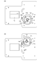
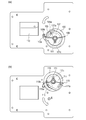
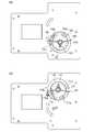
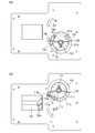
- shutter unit 20 As one embodiment of a shutter of the present invention. It is the figure which looked at the 1st rotor plate 107 (2nd rotor plate 117) from the back side. It is a figure explaining the state of the shutter unit 20 when it will be in A state. It is a figure explaining the state of the shutter unit 20 when it will be in B state. It is a figure explaining the state of the shutter unit 20 when it will be in C state. It is a figure explaining the state of the shutter unit 20 when it will be in D state. It is a figure explaining the state of the shutter unit 20 when it will be in an E state. It is a figure explaining the state of the shutter unit 20 when it will be in a F state.
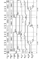
- FIG. 5 is a timing chart for explaining the operation of the shutter unit 20 at the time of continuous shooting operation of the camera 100.
- FIG. 5 is a timing chart illustrating an operation of the shutter unit 20 at the time of continuous shooting operation of the camera 100 as a modified example of the present embodiment.
- motor 1 used as the 1st motor Ma and the 2nd motor Mb. It is a figure explaining operation of motor 1.
- FIG. 5 is a timing chart for explaining the operation of the shutter unit 20 at the time of continuous shooting operation of the camera 100.
- FIG. 5 is a timing chart illustrating an operation of the shutter unit 20 at the time of continuous shooting operation of the camera 100 as a modified example of the present embodiment.
- motor 1 used as the 1st motor Ma and the 2nd motor Mb. It is a figure explaining operation of motor 1.
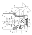
- FIG. 1 is a central cross-sectional view of a digital single-lens reflex camera main body 100 and an interchangeable lens 50 as an embodiment of an imaging device of the present invention.
- FIG. 17 is a central cross-sectional view of a digital single-lens reflex camera main body (hereinafter referred to as a camera) 100 and an interchangeable lens 50 as an embodiment of the imaging apparatus of the present invention.
- a camera digital single-lens reflex camera main body
- an interchangeable lens 50 as an embodiment of the imaging apparatus of the present invention.
- the interchangeable lens 50 is detachably fixed to the camera 100 by the mount unit 210 on the camera 100 side and the mount unit 51 on the interchangeable lens 50 side.
- the contact portion 120 of the camera 100 and the contact portion 52 of the interchangeable lens 50 are electrically connected.
- the light flux transmitted through the focus lens 53 of the interchangeable lens 50 is incident on the main mirror 130 of the camera 100.
- the main mirror 130 is held by the main mirror holding frame 131, and is pivotally supported between the mirror up position and the mirror down position by the rotation shaft portion 131a.
- the main mirror 130 is a half mirror, and the light beam transmitted through the main mirror 130 is reflected downward by the sub mirror 140 and guided to the focus detection unit 150.
- the sub mirror 140 is held by a sub mirror holding frame 141.
- the sub mirror holding frame 141 is pivotally supported relative to the main mirror holding frame 131 by a hinge shaft (not shown).
- the focus detection unit 150 detects the defocus amount of the focus lens 53, and calculates the drive amount of the focus lens 53 with which the focus lens 53 is in focus.
- the interchangeable lens 50 receives the calculated drive amount through the contact parts 220 and 52.
- the interchangeable lens 50 controls a motor (not shown) based on the received drive amount, and performs focus adjustment by driving the focus lens 53.
- the luminous flux reflected by the main mirror 130 is guided to the optical finder 160.
- the optical finder 160 is composed of a focusing screen 170, a pentaprism 180, and an eyepiece lens 190.
- the luminous flux guided to the optical finder 160 by the main mirror 130 forms an object image on the focusing plate 170.
- the user can observe the subject image on the focusing screen 170 through the pentaprism 180 and the eyepiece lens 190.
- a shutter unit 20 is disposed.
- An optical low pass filter 21, an imaging device holder 22, an imaging device 23, a cover member 24 and a rubber member 25 are disposed behind the shutter unit 20.
- a light flux transmitted through the optical low pass filter 21 is incident on the imaging device 23.
- the image sensor holder 22 is fixed to the housing of the camera 100 by screws (not shown).
- the imaging device 23 is held by an imaging device holder 22.
- the cover member 24 protects the imaging device 23.
- the rubber member 25 holds the optical low pass filter 21 and seals the space between the optical low pass filter 21 and the imaging device 23.
- the display monitor 26 is a monitor configured of an LCD or the like, and displays a captured image and displays various setting states of the camera 100.
- FIG. 1 is a view for explaining a shutter unit 20 as an embodiment of the shutter according to the present invention.
- FIG. 1A is an exploded perspective view illustrating the configuration of the shutter unit 20.
- FIG. 1B is an exploded perspective view of the shutter unit 20 further disassembled from the state illustrated in FIG.
- the shutter unit 20 is driven by the first motor Ma and the second motor Mb.
- the first motor Ma is connected to the drive circuit 14a
- the second motor Mb is connected to the drive circuit 14b.
- the drive circuit 14 a and the drive circuit 14 b are connected to the control circuit 13.
- the first motor Ma and the second motor Mb are the same motor.
- the pinion gear 101 is press-fitted to the output shaft of the first motor Ma.
- a pinion gear 111 is press-fitted to the output shaft of the second motor Mb.
- the first motor Ma is attached to the motor attachment plate 102, and the motor attachment plate 102 is fixed to the cover plate 103.
- the second motor Mb is attached to the motor attachment plate 112, and the motor attachment plate 112 is fixed to the cover plate 113.
- the drive mechanism accommodating portion 104 accommodates the first rotary plate 107 to which the weight 106 is adhered and the second rotary plate 117 to which the weight 116 is adhered.
- a projection 107 a is formed on the first rotary plate 107.
- the cover plate 103 is attached to the drive mechanism storage portion 104, the protrusion 107 a is exposed from the cover plate 103.
- a protrusion 117 a is formed on the second rotary plate 117.
- the cover plate 113 is attached to the drive mechanism storage portion 104, the protrusion 117a is exposed from the cover plate 113.
- a spring 108 is attached to the cover plate 103, and a spring 118 is attached to the cover plate 113.
- a gear portion 107 b is formed on the first rotary plate 107.
- the motor mounting plate 102 is fixed to the cover plate 103, the pinion gear 101 and the gear portion 107b mesh with each other.
- a gear portion 117 b is formed on the second rotary plate 117.
- the motor mounting plate 112 is fixed to the cover plate 113, the pinion gear 111 and the gear portion 117b mesh with each other.
- An aperture 105 a is formed in the blade housing portion 105.
- the blade storage unit 105 stores the first blade 110 and the second blade 120.
- a drive arm 110 a is attached to the first blade 110.
- the drive arm 120 a is attached to the second blade 120.
- a first drive lever 109 and a second drive lever 119 are each pivotally supported by the drive mechanism storage portion 104.
- a cam pin 109 a and an engagement pin 109 b are formed on the first drive lever 109.
- the cam pin 109 a engages with a cam groove 107 c formed in the first rotary plate 107.
- the engagement pin 109b engages with the drive arm 110a.
- a cam pin 119a and an engagement pin 119b are formed on the second drive lever 119.
- the cam pin 119 a engages with a cam groove 117 c formed in the second rotary plate 117.
- the engagement pin 119b engages with the drive arm 120a.
- the first drive lever 119 and the second drive lever 119 are the same component.
- a shaft portion 104 a and a shaft portion 104 b are formed in the drive mechanism storage portion 104.
- the first rotary plate 107 is pivotally supported by the shaft portion 104a, and the second rotary plate 117 is pivotally supported by the shaft portion 104b.
- a gear portion 107 b is formed on the surface of the first rotary plate 107, and the weight 106 is adhesively fixed to the outer peripheral portion of the first rotary plate 107.
- a cam groove 107c engaged with the cam pin 109a is formed on the back surface of the first rotating plate 107.
- a gear portion 117 b is formed on the surface of the second rotary plate 117, and the weight 116 is adhesively fixed to the outer peripheral portion of the second rotary plate 117.
- a cam groove 117c engaged with the cam pin 119a is formed on the back surface of the second rotary plate 117.
- the first rotary plate 107 and the second rotary plate 117 are the same component.
- the weight 106 and the weight 116 are also the same parts.
- the first rotary plate 107 and the second rotary plate 117 function as driven members.
- the first blade 110 and the first drive lever 109 function as a light shielding member movable in a closed state in which the aperture 105a is closed in conjunction with the driving of the first rotary plate 107 and in an open state in which the aperture 105a is opened.
- the second blade 120 and the second drive lever 119 function as a light blocking member movable in a closed state in which the aperture 105a is closed in conjunction with the drive of the second rotary plate 117 and in an open state in which the aperture 105a is opened.
- the spring 108 and the spring 118 function as a biasing member.
- FIG. 2 is a view of the first rotary plate 107 (second rotary plate 117) viewed from the back side.
- a cam groove 107c (cam groove 117c) engaged with the cam pin 109a (cam pin 119a) is formed on the back surface of the first rotary plate 107 (second rotary plate 117).
- a first idle driving area A, an exposure driving area B, and a second idle driving area C are set in the cam groove 107c (cam groove 117c).
- the cam lift is almost zero.
- the first idle driving area A is a first cam area, and the section in which the cam pins 109a (cam pins 119a) trace the first idle driving area A is a first section.
- the exposure drive area B is the second cam area, and the section in which the cam pins 109a (cam pins 119a) trace the exposure drive area B is the second section.
- the idle driving area C is a third cam area, and the section in which the cam pins 109a (cam pins 119a) trace the second idle driving area C is a third section.
- the second idle driving area C is the first cam area, and the section in which the cam pins 109a (cam pins 119a) trace the second idle driving area C is the first section.
- the exposure drive area B is the second cam area, and the section in which the cam pins 109a (cam pins 119a) trace the exposure drive area B is the second section.
- the first idle driving area A is a third cam area, and the section in which the cam pins 109a (cam pins 119a) trace the first idle driving area A is a third section.
- the first rotary plate 107 (second rotary plate 117) is driven in the first section. Then, after the first rotary plate 107 (second rotary plate 117) is driven in the first section, the first rotary plate 107 (second rotary plate 117) is driven in the second section.
- a hollow shaft portion 103 a is formed on the cover plate 103.
- the cover plate 103 is attached to the drive mechanism accommodating portion 104, the projection 107a of the first rotary plate 107 is exposed from the cover plate 103, and the shaft portion 104a is fitted to the inner diameter portion of the hollow shaft portion 103a.
- the first spring 108 is attached to the outer diameter portion of the hollow shaft portion 103a.
- a hollow shaft portion 113 a is formed on the cover plate 113.
- the cover plate 113 is attached to the drive mechanism accommodating portion 104, the projection 117a of the second rotary plate 117 is exposed from the cover plate 103, and the shaft portion 104b is fitted to the inner diameter portion of the hollow shaft portion 113a.
- the second spring 118 is attached to the outer diameter portion of the hollow shaft portion 113a.
- the first motor Ma, the first rotary plate 107, the first spring 108, the first drive lever 109, and the first blade 110 are referred to as a first shutter drive mechanism.
- the second motor Mb, the second rotary plate 117, the second spring 118, the second drive lever 119, and the second blade 120 are referred to as a second shutter drive mechanism.
- the first motor Ma and the second motor Mb are capable of performing two types of feedback drive with different types of advance angle and step drive (open loop drive) that switches and drives the energization state of the coil according to a determined time interval. It is a motor.
- step drive mode open loop drive mode
- drive is performed to switch the energization state of the coil in accordance with the determined time interval.
- first motor Ma and the second motor Mb are driven in the feedback drive mode, drive is performed to switch the energization state of the coil according to the output of the position sensor.
- FIG. 12 is a timing chart for explaining the operation of the shutter unit 20 during the continuous shooting operation of the camera 100.
- FIGS. 3 to 11 are diagrams for explaining the state of the shutter unit 20 in the A state to the I state shown in FIG.
- the shutter unit 20 of the present embodiment performs the photographing operation for the first frame from the A state to the H state shown in FIG.
- the first shutter drive mechanism functions as a front curtain
- the second shutter drive mechanism functions as a rear curtain.
- the shutter unit 20 of the present embodiment performs the photographing operation for the second frame in the H state to the I state shown in FIG.
- the second shutter drive mechanism functions as a front curtain
- the first shutter drive mechanism functions as a rear curtain.
- the first shutter drive mechanism functions as a front curtain
- the second shutter drive mechanism functions as a rear curtain.
- FIG. 3 is a diagram for explaining the state of the shutter unit 20 when it is in the A state.
- FIG. 3A is a view for explaining the state of the first shutter drive mechanism.
- FIG. 3B is a view for explaining the state of the second shutter drive mechanism.
- the first blade 110 closes the aperture 105a.
- the protrusion 107 a of the first rotary plate 107 is in contact with the left arm of the first spring 108.
- the first spring 108 is not charged and is in a natural state.
- the second blade 120 opens the aperture 105a.
- the projection 117 a of the second rotary plate 117 is in contact with the right arm of the second spring 118.
- the second spring 118 is not charged and is in a natural state.
- the control circuit 13 controls the drive circuit 14 a so as to drive the first motor Ma clockwise in the low advance feedback drive mode in the A state. Further, the control circuit 13 controls the drive circuit 14b so as not to drive the second motor Mb in any direction in the A state. By this, the shutter unit 20 is in the state B shown in FIG.
- FIG. 4 is a diagram for explaining the state of the shutter unit 20 when the state B is reached.
- FIG. 4A is a view for explaining the state of the first shutter drive mechanism.
- FIG. 4B is a view for explaining the state of the second shutter drive mechanism.
- the first blade 110 closes the aperture 105a.
- the first rotary plate 107 is not shown in FIG. Rotate counterclockwise from the state shown in).
- the pinion gear 101 of the first motor Ma and the gear portion 107b of the first rotary plate 107 are engaged, the rotational direction of the first motor Ma and the rotational direction of the first rotary plate 107 are opposite.
- the B state of the second shutter drive mechanism illustrated in FIG. 4B is the same as the A state of the second shutter drive mechanism illustrated in FIG.
- the second motor Mb is not driven, so there is no change from the state (state A) illustrated in FIG. 3B.
- the control circuit 13 controls the drive circuit 14 a so as to drive the first motor Ma counterclockwise in the step drive mode in the B state. Further, the control circuit 13 controls the drive circuit 14 b to drive the second motor Mb clockwise in the low advance feedback drive mode in the B state.
- the shutter unit 20 is in the state C shown in FIG. That is, in the present embodiment, the start-up drive start in the second shutter drive mechanism is delayed from the start-up drive start in the first shutter drive mechanism by the exposure time t1.
- the first shutter drive mechanism starts the approach drive in the step drive mode from the B state.
- the control circuit 13 gradually increases the rotational speed of the first motor Ma by gradually reducing the width of the drive pulse.
- the cam pin 109a traces a first free running drive area A of the cam groove 107c at which the cam lift is almost zero. Therefore, in this section, since the first drive lever 109 does not substantially rotate even when the first rotary plate 107 is driven, the load fluctuation during the driving of the first motor Ma is small, so the first motor Ma is step-driven. Even when driven in the mode, the first motor Ma is not out of step.
- FIG. 5 is a diagram for explaining the state of the shutter unit 20 when it is in the C state.
- FIG. 5A is a view for explaining the state of the first shutter drive mechanism.
- FIG. 5B is a view for explaining the state of the second shutter drive mechanism.
- the first blade 110 closes the aperture 105a. Since the first motor Ma is driven counterclockwise between the B state and the C state, the first rotary plate 107 is rotated clockwise by the resultant force of the driving force of the first motor Ma and the biasing force of the first spring 108. To rotate. The biasing force of the first spring 108 is applied to the first rotary plate 107 until the C state shown in FIG. 5A.
- the second blade 120 opens the aperture 105a. Since the second motor Mb is driven clockwise in the low advance feedback drive mode from the B state to the C state, the second rotary plate 117 rotates counterclockwise from the state shown in FIG. 4B. Rotate.
- the pinion gear 111 of the second motor Mb meshes with the gear portion 117b of the second rotary plate 117, the rotational direction of the second motor Mb and the rotational direction of the second rotary plate 117 are opposite.
- the control circuit 13 controls the drive circuit 14 a so as to drive the first motor Ma counterclockwise in the step drive mode even in the C state. Further, the control circuit 13 controls the drive circuit 14 b to drive the second motor Mb counterclockwise in the step drive mode in the C state.
- the shutter unit 20 is in the D state shown in FIG.
- the second shutter drive mechanism starts the approach drive in the step drive mode from the C state.
- the control circuit 13 gradually increases the rotational speed of the second motor Mb by gradually reducing the width of the drive pulse.
- the cam pin 119a traces the first free running drive area A of the cam groove 117c at which the cam lift is almost zero. As a result, even if the second motor Mb is driven in the step drive mode, the second motor Mb does not step out.
- FIG. 6 is a diagram for explaining the state of the shutter unit 20 when it is in the D state.
- FIG. 6A is a view for explaining the state of the first shutter drive mechanism.
- FIG. 6B is a view for explaining the state of the second shutter drive mechanism.
- the second blade 120 opens the aperture 105a. Since the second motor Mb is driven in the counterclockwise direction between the C state and the D state, the second rotary plate 117 is driven by the combined force of the driving force of the second motor Mb and the biasing force of the second spring 118. , Rotate clockwise.
- the biasing force of the second spring 118 is applied to the second rotary plate 117 before the state D shown in FIG. 6B. That is, in the state D shown in FIG. 6B, the urging force of the second spring 118 is not applied to the second rotary plate 117, and the second rotary plate 117 is operated only by the driving force of the second motor Mb. Rotate clockwise.
- the control circuit 13 controls the drive circuit 14 a so as to drive the first motor Ma counterclockwise in the high advance feedback drive mode. Further, even in the D state, the control circuit 13 controls the drive circuit 14 b so as to drive the second motor Mb counterclockwise in the step drive mode.
- the shutter unit 20 is in the state E shown in FIG.
- the first shutter drive mechanism starts the exposure drive in the high advance angle feedback drive mode from the D state.
- FIG. 7 is a view for explaining the state of the shutter unit 20 when it is in the E state.
- FIG. 7A is a view for explaining the state of the first shutter drive mechanism.
- FIG. 7B is a view for explaining the state of the second shutter drive mechanism.
- the first blade 110 opens the aperture 105a. Since the first motor Ma is driven counterclockwise between the D state and the E state, the first rotary plate 107 is rotated clockwise by the driving force of the first motor Ma.
- the control circuit 13 controls the drive circuit 14a so as to drive the first motor Ma counterclockwise in the high advance feedback drive mode even in the E state. Further, the control circuit 13 controls the drive circuit 14b so as to drive the second motor Mb counterclockwise in the feedback drive mode with a high advance angle in the E state.
- the shutter unit 20 is in the F state shown in FIG.
- the second shutter drive mechanism starts the exposure drive in the feedback drive mode with a high advance angle from the E state.
- FIG. 8 is a diagram for explaining the state of the shutter unit 20 when it is in the F state.
- FIG. 8A is a view for explaining the state of the first shutter drive mechanism.
- FIG. 8B is a view for explaining the state of the second shutter drive mechanism.
- the first blade 110 opens the aperture 105a. Since the first motor Ma is driven counterclockwise between the D state and the E state, the first rotary plate 107 is rotated clockwise by the driving force of the first motor Ma.
- the second blade 120 closes the aperture 105a. Since the second motor Mb is driven counterclockwise between the E state and the F state, the second rotary plate 117 rotates clockwise by the driving force of the second motor Mb.
- the control circuit 13 controls the drive circuit 14 a so as to drive the first motor Ma in the counterclockwise direction in the feedback drive mode with a high advance angle even in the F state. Further, even in the F state, the control circuit 13 controls the drive circuit 14 b so as to drive the second motor Mb counterclockwise in the high advance feedback drive mode. By this, the shutter unit 20 is in the G state shown in FIG.
- FIG. 9 is a diagram for explaining the state of the shutter unit 20 when it is in the G state.
- FIG. 9A is a view for explaining the state of the first shutter drive mechanism.
- FIG. 9B is a view for explaining the state of the second shutter drive mechanism.
- the first blade 110 opens the aperture 105a.
- the first motor Ma is driven counterclockwise.
- the projection 107a of the first rotary plate 107 abuts on the right arm of the first spring 108, and the first rotary plate 107 rotates clockwise while charging the first spring 108. . That is, the first spring 108 acts to brake the clockwise rotation of the first rotary plate 107.
- the first rotary plate 107 is biased in the counterclockwise direction by the first spring 108.
- the second blade 120 closes the aperture 105a. Since the second motor Mb is driven counterclockwise between the F state and the G state, the second rotary plate 117 rotates clockwise by the driving force of the second motor Mb. In the state illustrated in FIG. 9B, the projection 117a of the second rotary plate 117 is in contact with the left arm of the second spring 118. However, in this state, the second spring 118 is not charged and is in a natural state.
- the control circuit 13 controls the drive circuit 14 a to hold and energize the first motor Ma in the G state.
- the hold energization is to maintain the energization phase to the coil of the first motor Ma when it becomes the G state.
- the control circuit 13 controls the drive circuit 14 b so as to drive the second motor Mb counterclockwise in the high advance feedback drive mode. By this, the shutter unit 20 is in the H state shown in FIG.
- FIG. 10 is a diagram for explaining the state of the shutter unit 20 when it is in the H state.
- FIG. 10A is a view for explaining the state of the first shutter drive mechanism.
- FIG. 10B is a view for explaining the state of the second shutter drive mechanism.
- the first blade 110 opens the aperture 105a.
- the first motor Ma and the first rotary plate 107 are maintained in the G state because the first motor Ma is energized in the G state. That is, the state (H state) illustrated in FIG. 10 (a) is the same state as the state (G state) illustrated in FIG. 9 (a).
- the second blade 120 closes the aperture 105a.
- the second motor Ma is driven counterclockwise between the G state and the H state.
- the protrusion 117a of the second rotary plate 117 abuts on the left arm of the second spring 118 during the G state to the H state, and the second rotary plate 117 rotates clockwise while charging the second spring 118. . That is, the second spring 118 acts to brake the clockwise rotation of the second rotary plate 117.
- the second rotary plate 117 is biased by the second spring 118 in the counterclockwise direction.
- the shutter unit 20 performs the photographing operation for the first frame from the A state to the H state shown in FIG.
- the first shutter drive mechanism functions as a front curtain
- the second shutter drive mechanism functions as a rear curtain
- the first shutter drive mechanism functions as a rear curtain. That is, in the photographing operation of the first frame, the first shutter drive mechanism performs the exposure operation prior to the second shutter driving mechanism, and in the photographing operation of the second frame, the second shutter drive mechanism performs the first operation. The exposure operation is performed prior to the shutter drive mechanism.
- the start drive start in the first shutter drive mechanism is delayed from the start drive start in the second shutter drive mechanism by the exposure time t2 of the second frame.
- the control circuit 13 controls the drive circuit 14a to hold and energize the first motor Ma even in the H state. Further, the control circuit 13 controls the drive circuit 14b to drive the second motor Mb clockwise in the step drive mode in the H state. As a result, the second rotary plate 117 is rotated counterclockwise by the driving force of the second motor Mb and the biasing force of the second spring 118.
- the second shutter drive mechanism starts the approach drive in the step drive mode from the H state.
- the shutter unit 20 is in the state of G 'illustrated in FIG.
- the state of the shutter unit 20 in the G 'state shown in FIG. 12 is the same as the state shown in FIG.
- the control circuit 13 controls the drive circuit 14 a to drive the first motor Ma clockwise in the step drive mode in the G ′ state.
- the first rotary plate 107 rotates counterclockwise by the driving force of the first motor Ma and the biasing force of the first spring 108.
- the first shutter drive mechanism starts the approach drive in the step drive mode from the G 'state.
- the control circuit 13 also controls the drive circuit 14 b to drive the second motor Mb clockwise in the step drive mode even in the G ′ state.
- the shutter unit 20 is in the state of F 'shown in FIG.
- the state of the shutter unit 20 in the F 'state shown in FIG. 12 is the same as the state shown in FIG.
- the control circuit 13 also controls the drive circuit 14 a so as to drive the first motor Ma clockwise in the step drive mode even in the F ′ state.
- the control circuit 13 also controls the drive circuit 14 b to drive the second motor Mb clockwise in the high advance feedback drive mode in the F ′ state.
- the shutter unit 20 is in the state of E 'shown in FIG.
- the second shutter drive mechanism starts the exposure drive in the high advance angle feedback drive mode from the F 'state. Since the rotational speed of the second motor Mb is sufficiently high in the propulsive drive, the second motor Mb can be driven in the high advance feedback drive mode.
- the state of the shutter unit 20 in the F 'state shown in FIG. 12 is the same as the state shown in FIG.
- the control circuit 13 controls the drive circuit 14a so as to drive the first motor Ma clockwise in the high advance feedback drive mode in the E 'state.
- the control circuit 13 also controls the drive circuit 14 b to drive the second motor Mb clockwise in the high advance feedback drive mode even in the E ′ state.
- the shutter unit 20 is in the state of D 'shown in FIG.
- the first shutter drive mechanism starts the exposure drive in the high advance feedback drive mode from the E 'state. Since the rotational speed of the first motor Mba is sufficiently high by the run-up drive, the first motor Ma can be driven in the high advance feedback drive mode.
- the state of the shutter unit 20 in the E ′ state illustrated in FIG. 12 is the same as the state illustrated in FIG.
- the control circuit 13 controls the drive circuit 14 a so as to drive the first motor Ma clockwise in the high advance feedback drive mode even in the D ′ state.
- the control circuit 13 also controls the drive circuit 14 b to drive the second motor Mb clockwise in the high advance feedback drive mode even in the D ′ state.
- the shutter unit 20 is in the state of C 'shown in FIG.
- the state of the shutter unit 20 in the C 'state shown in FIG. 12 is the same as the state shown in FIG.
- the control circuit 13 also controls the drive circuit 14 a so as to drive the first motor Ma clockwise in the high advance feedback drive mode even in the C ′ state. Further, the control circuit 13 controls the drive circuit 14b to hold and energize the second motor Mb in the C 'state.
- holding and supplying current means maintaining the current supplying phase to the second motor Mb when the D 'state is achieved. By this, the shutter unit 20 is in the I state shown in FIG.
- FIG. 11 is a diagram for explaining the state of the shutter unit 20 when it is in the I state.
- FIG. 11A is a view for explaining the state of the first shutter drive mechanism.
- FIG. 11B is a view for explaining the state of the second shutter drive mechanism.
- the first blade 110 closes the aperture 105a.
- the first rotary plate 107 rotates counterclockwise from the state shown in FIG. 5A. Do. Between the C 'state and the I state, the protrusion 107a of the first rotary plate 107 abuts on the left arm of the first spring 108, and the first rotary plate 107 rotates counterclockwise while charging the first spring 108. Do. That is, the first spring 108 acts to brake the counterclockwise rotation of the first rotary plate 107. In the state shown in FIG. 11A, since the first spring 108 is charged, the first rotary plate 107 is urged clockwise by the first spring 108.
- the second blade 120 opens the aperture 105a. Since the second motor Mb is held and energized in the C 'state, the second motor Mb and the twelfth rotating plate 117 maintain the C' state. That is, the state shown in FIG. 5 (b) is the same as the state shown in FIG. 11 (b).
- the shutter unit 20 performs the photographing operation for the second frame from the H state to the I state shown in FIG.
- the second shutter drive mechanism functions as a front curtain
- the first shutter drive mechanism functions as a rear curtain
- the second shutter drive mechanism functions as a rear curtain.
- the start drive start in the second shutter drive mechanism is delayed from the start drive start in the first shutter drive mechanism by the exposure time t3 of the third frame.
- control circuit 13 controls the drive circuit 14 a so as to drive the first motor Ma counterclockwise in the step drive mode in the I state. Further, the control circuit 13 controls the drive circuit 14 b to hold and energize the second motor Mb.
- the shutter unit 20 is in the state C shown in FIG.
- FIG. 13 is a timing chart for explaining the operation of the shutter unit 20 during continuous shooting operation of the camera 100 as a modification of the present embodiment.
- the delay of the front curtain and the rear curtain is created by changing the run start drive start timing in the shutter drive mechanism functioning as the front curtain and the run start drive timing in the shutter drive mechanism functioning as the rear curtain.
- the front curtain and the rear curtain can be changed by changing the pulse rate of the run drive in the shutter drive mechanism functioning as the front curtain and the pulse rate of the run drive in the shutter drive mechanism functioning as the rear curtain.
- Create a delay That is, the pulse rate of the approach drive in the shutter drive mechanism that functions as the rear curtain is made larger than the pulse rate of the approach drive in the shutter drive mechanism that functions as the front curtain.
- the required time for the entry drive in the shutter drive mechanism functioning as the rear curtain is longer than the required time for the launch drive in the shutter drive mechanism functioning as the front curtain.
- the control circuit 13 controls the drive circuit 14a so as to drive the first motor Ma clockwise in the low advance feedback drive mode. Further, in the state A illustrated in FIG. 13, the control circuit 13 controls the drive circuit 14 b so as to drive the second motor Mb clockwise in the low advance feedback drive mode.
- the shutter unit 20 is in the I state shown in FIG.
- the control circuit 13 controls the drive circuit 14 a to drive the first motor Ma counterclockwise in the step drive mode. Further, in the I state shown in FIG. 13, the control circuit 13 controls the drive circuit 14b so as to drive the second motor Mb counterclockwise in the step drive mode. By this, the shutter unit 20 is in the D state shown in FIG.
- the D state to the G state shown in FIG. 13 are the same as the D state to the G state shown in FIG. 12 in the embodiment described above.
- control circuit 13 controls the drive circuit 14 a so as to drive the first motor Ma counterclockwise in the feedback drive mode with a high advance angle. Also in the state D shown in FIG. 13, the control circuit 13 controls the drive circuit 14b to drive the second motor Mb counterclockwise in the feedback drive mode with a high advance angle.
- the control circuit 13 controls the drive circuit 14 a to hold and energize the first motor Ma in the G state illustrated in FIG. 12.
- the control circuit 13 controls the drive circuit 14a so as to drive the first motor Ma in the counterclockwise direction in the high advance feedback drive mode. Therefore, although the first rotary plate 107 tries to rotate clockwise, the projection 107a of the first rotary plate 107 abuts on the stopper formed on the cover plate 103, so that the first rotary plate 107 rotates clockwise. Is blocked.
- This embodiment is the same as the above-described embodiment, except for the method of creating the delay of the front curtain and the rear curtain and the point that the holding energization is not performed.
- FIG. 14 is a view for explaining the motor 1 used as the first motor Ma and the second motor Mb described above. Note that, for the sake of explanation, some parts are shown broken.
- the rotor 3 includes a magnet 2 and is rotatably controlled by a control circuit (control unit) 13 and a drive circuit 14.
- the magnet 2 is formed in a cylindrical shape, and the outer peripheral surface is divided in the circumferential direction, and multipole magnetization is alternately performed on different poles. In this embodiment, it is magnetized in eight divisions, that is, in eight poles. In addition, you may magnetize not only in 8 poles but in 4 poles or 12 poles.
- the first coil 4 is disposed at one end of the magnet 2 in the axial direction.
- the first yoke 6 is made of a soft magnetic material and is formed to face the outer peripheral surface of the magnet 2 with a gap. Further, the first yoke 6 is provided with a plurality of first magnetic pole portions 6 a axially extended from the annular main body portion and arranged at predetermined intervals in the circumferential direction. The first magnetic pole portion 6 a is excited by energization of the first coil 4.
- a first stator unit is configured of the first coil 4, the first yoke 6, and the magnets 2 facing the plurality of first magnetic pole portions 6 a.
- the second coil 5 is disposed at one end opposite to the one end in the axial direction to which the first coil 4 of the magnet 2 is attached.
- the second yoke 7 is made of a soft magnetic material and is formed so as to face the outer peripheral surface of the magnet 2 with a gap. Further, the second yoke 7 is provided with a plurality of second magnetic pole portions 7a axially extended from the annular main body portion and arranged at predetermined intervals in the circumferential direction. The second magnetic pole portion 7 a is excited by energization of the second coil 5.
- a second stator unit is constituted by the magnets 2 facing the second coil 5, the second yoke 7, and the plurality of second magnetic pole portions 7a.
- the torque given to the rotor 3 can be changed by switching the poles (N pole, S pole) excited in the first magnetic pole portion 6 a and the second magnetic pole portion 7 a.
- First magnetic sensor (first detection element) 8, second magnetic sensor (second detection element) 9, third magnetic sensor (third detection element) 10, fourth magnetic sensor (fourth detection element) 11 constitutes a detection means.
- Each magnetic sensor is a Hall element that detects the magnetic flux of the magnet 2 and is fixed to the motor cover 12.
- the motor cover 12 has the first yoke 6 and the second yoke 6 so that the first magnetic pole portion 6a and the second magnetic pole portion 7a are disposed so as to be shifted by approximately 90 degrees in electrical angle with respect to the magnetization phase of the magnet 2. Hold the yoke 7 of the
- the electrical angle of 90 degrees is 22.5 degrees in mechanical angle.
- the control circuit 13 can drive by switching between step driving and two types of feedback driving with different advance amounts.
- the control circuit 13 controls the drive circuit 14 so as to switch the conduction state of the first coil 4 and the second coil 5 at predetermined time intervals. That is, when performing step driving, the outputs of the first magnetic sensor 8, the second magnetic sensor 9, the third magnetic sensor 10, and the fourth magnetic sensor 11 are not used.
- control circuit 13 performs feedback drive.
- the control circuit 13 performs two types of feedback driving, the outputs of the first magnetic sensor 8, the second magnetic sensor 9, the third magnetic sensor 10, and the fourth magnetic sensor 11 are used.
- a large rotational driving force can be obtained even at the time of switching of the energization direction by providing the magnetic sensors in the positional relationship as described below with respect to each yoke.
- FIG. 15 is a diagram for explaining the operation of the motor 1. The actual operation of the motor 1 will be described using FIGS. 15 (a) to 15 (i). The state of FIG. 15A will be described as an initial state at the time of driving.
- the excitation of the first magnetic pole portion 6a is switched by the output signal of the first magnetic sensor 8, and the excitation of the second magnetic pole portion 7a is switched by the output signal of the second magnetic sensor 9. Then, the rotor 3 is rotated clockwise.
- the clockwise rotation direction of the rotor 3 corresponds to the first rotation direction.
- the control circuit 13 controls the drive circuit 14 so as to excite the first magnetic pole portion 6 a to the N pole.
- the detection signal is input to the control circuit 13. Then, the control circuit 13 controls the drive circuit 14 so as to excite the first magnetic pole portion 6 a to the S pole.
- the control circuit 13 controls the drive circuit 14 so as to excite the second magnetic pole portion 7 a to the S pole.
- the control circuit 13 controls the drive circuit 14 so as to excite the second magnetic pole portion 7 a to the N pole.
- the first magnetic sensor 8 and the second magnetic sensor 9 both detect the south pole of the magnet 2.
- the control circuit 13 controls the drive circuit 14 so that the first magnetic pole portion 6a is excited to the N pole and the second magnetic pole portion 7a is excited to the S pole.
- clockwise rotational force is generated on the rotor 3 and the magnet 2.
- the timing of the excitation switching of the first magnetic pole portion 6a with respect to the rotational position of the rotor 3 is 0 to 45 electrical degrees.
- the first magnetic sensor 8 is disposed so as to be between two degrees.
- the first magnetic sensor 8 detects the N pole (switch from S pole to N pole) of the magnet 2.
- the drive circuit 14 energizes the first coil 4 so that the first magnetic pole portion 6 a is excited to the S pole.
- the second magnetic sensor 9 detects the south pole of the magnet 2 between the state of FIG. 15 (b) and the state of FIG. 15 (c), the second magnetic pole portion 7a is excited to the south pole.
- the drive circuit 14 energizes the second coil 5.
- clockwise rotational force is generated on the rotor 3 and the magnet 2.
- the timing of the excitation switching of the second magnetic pole portion 7 a with respect to the rotational position of the rotor 3 is 0 ° electrical advance angle 45
- the second magnetic sensor 9 is disposed so as to be between two degrees.
- the second magnetic sensor 9 detects the N pole (switch from S pole to N pole) of the magnet 2.
- the drive circuit 14 energizes the second coil 5 so that the second magnetic pole portion 7 a is excited to the N pole.
- the first magnetic sensor 8 detects the N pole of the magnet 2 from the state of FIG. 15D to the state of FIG. 15E, the first magnetic pole portion 6a becomes an S pole.
- the drive circuit 14 energizes the first coil 4 so as to be excited. By this, the rotor 3 and the magnet 2 generate clockwise rotational force.
- the energization of the first coil 4 and the second coil 5 is sequentially switched by the outputs of the first magnetic sensor 8 and the second magnetic sensor 9, and the rotor 3
- the magnet 2 rotates in the clockwise direction.
- the excitation switching of the first magnetic pole portion 6a with respect to the rotational position of the rotor 3 The timing is between 0 and 45 degrees of electrical advance. That is, in the first magnetic sensor 8, the advance amount from the position where the electrical advance angle is 0 degrees from the excitation switching timing in the first magnetic pole portion 6a is the electrical advance from the excitation switching timing in the first magnetic pole portion 6a. It is disposed at a position smaller than the retardation amount from the position of 90 degrees.
- the excitation switching of the second magnetic pole portion 7a with respect to the rotational position of the rotor 3 The timing is between 0 and 45 electrical degrees. That is, in the second magnetic sensor 9, the advance amount from the position where the electrical advance angle is 0 degree from the excitation switching timing in the second magnetic pole portion 7a is the electrical advance from the excitation switching timing in the second magnetic pole portion 7a. It is disposed at a position smaller than the retardation amount from the position of 90 degrees.
- High advance angle drive (second energization mode)
- the clockwise high advance drive mode will be described.
- the high advance drive mode can be rotated faster than the low advance drive mode described above.
- the pole excited to the first magnetic pole portion 6 a is switched based on the output of the third magnetic sensor 10, and the second magnetic pole portion 7 a is switched based on the output of the fourth magnetic sensor 11.
- the rotor 3 is rotated clockwise by switching the pole to be excited in this drive mode.
- the conduction direction of the first coil 4 and the second coil 5 is switched in the following combination.
- the detection signal is input to the control circuit 13. Then, the control circuit 13 controls the drive circuit 14 so as to excite the first magnetic pole portion 6 a to the N pole.
- the control circuit 13 controls the drive circuit 14 so as to excite the first magnetic pole portion 6 a to the S pole.
- the detection signal is input to the control circuit 13. Then, the control circuit 13 controls the drive circuit 14 so as to excite the second magnetic pole portion 7 a to the S pole.
- the detection signal is input to the control circuit 13. Then, the control circuit 13 controls the drive circuit 14 so as to excite the second magnetic pole portion 7 a to the N pole.
- the third magnetic sensor 10 and the fourth magnetic sensor 11 both detect the south pole of the magnet 2. Therefore, when the first magnetic pole portion 6a is excited to the N pole and the second magnetic pole portion 7a is excited to the S pole, clockwise rotational force is generated in the rotor 3 and the magnet 2.
- the excitation switching timing of the first magnetic pole portion 6a with respect to the rotational position of the rotor 3 is 45 degrees of electrical advance angle 90 degrees
- the third magnetic sensor 10 is disposed to be in between.
- the third magnetic sensor 10 detects the N pole (switch from S pole to N pole) of the magnet 2.
- the drive circuit 14 energizes the first coil 4 so that the first magnetic pole portion 6 a is excited to the S pole.
- the fourth magnetic sensor 11 detects the S pole of the magnet 2 between the state of FIG. 15A and the state of FIG. 15B, the second magnetic pole portion 7a is excited to the S pole.
- the drive circuit 14 energizes the second coil 5. As a result, clockwise rotational force is generated on the rotor 3 and the magnet 2.
- the excitation switching timing of the second magnetic pole portion 7a with respect to the rotational position of the rotor 3 The fourth magnetic sensor 11 is disposed at an interval.
- the fourth magnetic sensor 11 detects the N pole (switch from S pole to N pole) of the magnet 2.
- the drive circuit 14 energizes the second coil 5 so that the second magnetic pole portion 7 a is excited to the N pole.
- the third magnetic sensor 10 detects the N pole of the magnet 2 between the state of FIG. 15C and the state of FIG. 15D, the first magnetic pole portion 6a is excited to the S pole.
- the drive circuit 14 energizes the first coil 4. By this, the rotor 3 and the magnet 2 generate clockwise rotational force.
- the energization of the first coil 4 and the second coil 5 is sequentially switched by the outputs of the third magnetic sensor 10 and the fourth magnetic sensor 11, and the rotor 3
- the magnet 2 rotates in the clockwise direction.
- the excitation switching of the first magnetic pole portion 6a with respect to the rotational position of the rotor 3 The timing is between 45 degrees and 90 degrees of electrical advance. That is, in the third magnetic sensor 10, the advance amount from the position where the electrical advance angle is 0 degrees from the excitation switching timing in the first magnetic pole portion 6a is the electrical advance from the excitation switching timing in the first magnetic pole portion 6a. It is disposed at a position where the retardation amount from the position of 90 degrees is larger.
- the excitation switching of the second magnetic pole portion 7a with respect to the rotational position of the rotor 3 The timing is between 45 degrees and 90 degrees of electrical advance. That is, in the fourth magnetic sensor 11, the advance amount from the position where the electrical advance angle is 0 degrees from the excitation switching timing in the second magnetic pole portion 7a is the electrical advance from the excitation switching timing in the second magnetic pole portion 7a. It is disposed at a position where the retardation amount from the position of 90 degrees is larger.
- the excitation of the first magnetic pole portion 6a is switched by the output signal of the third magnetic sensor 10, and the excitation of the second magnetic pole portion 7a is switched by the output signal of the fourth magnetic sensor 11. Then, the rotor 3 is rotated counterclockwise.
- the counterclockwise rotation direction of the rotor 3 corresponds to a second rotation direction opposite to the first rotation direction.
- the detection signal is input to the control circuit 13. Then, the control circuit 13 controls the drive circuit 14 so as to excite the first magnetic pole portion 6 a to the S pole.
- the detection signal is input to the control circuit 13. Then, the control circuit 13 controls the drive circuit 14 so as to excite the first magnetic pole portion 6 a to the N pole.
- the control circuit 13 controls the drive circuit 14 so as to excite the second magnetic pole portion 7 a to the N pole.
- the control circuit 13 controls the drive circuit 14 so as to excite the second magnetic pole portion 7 a to the S pole.
- the third magnetic sensor 10 and the fourth magnetic sensor 11 both detect the south pole of the magnet 2.
- the control circuit 13 controls the drive circuit 14 so that the first magnetic pole portion 6a is excited to the S pole and the second magnetic pole portion 7a is excited to the N pole.
- a counterclockwise rotational force is generated on the rotor 3 and the magnet 2.
- the distance between the center Q1 of the S pole of the magnet 2 and the second magnetic pole portion 7a is The distance is the same as the distance between the center Q3 of the N pole and the first magnetic pole portion 6a.
- the timing of the excitation switching of the second magnetic pole portion 7 a with respect to the rotational position of the rotor 3 is 0 ° electrical advance angle 45
- the fourth magnetic sensor 11 is disposed so as to be between two degrees.
- the N pole (switch from S pole to N pole) of the magnet 2 is detected.
- the drive circuit 14 energizes the second coil 5 so that the second magnetic pole portion 7 a is excited to the S pole.
- the third magnetic sensor 10 detects the S pole of the magnet 2 between the state of FIG. 15F and the state of FIG. 15G, the first magnetic pole portion 6a is excited to the S pole.
- the drive circuit 14 energizes the first coil 4. As a result, a counterclockwise rotational force is generated on the rotor 3 and the magnet 2.
- the excitation switching timing of the first magnetic pole portion 6a with respect to the rotational position of the rotor 3 is 0 degrees electrical advance angle 45 degrees
- the third magnetic sensor 10 is disposed so as to be in between.
- the third magnetic sensor 10 detects the N pole (switch from S pole to N pole) of the magnet 2.
- the drive circuit 14 energizes the first coil 4 so that the first magnetic pole portion 6 a is excited to the N pole.
- the fourth magnetic sensor 11 detects the N pole of the magnet 2 from the state of FIG. 15H to the state of FIG. 15I, the second magnetic pole portion 7a is excited to the S pole.
- the drive circuit 14 energizes the second coil 5. By this, the rotor 3 and the magnet 2 generate counterclockwise rotational force.
- the pole excited to the first magnetic pole portion 6 a is switched based on the output of the first magnetic sensor 8, and the second magnetic pole portion 7 a is switched based on the output of the second magnetic sensor 9.
- the rotor 3 is rotated counterclockwise by switching the pole to be excited.
- the control circuit 13 controls the drive circuit 14 so as to excite the first magnetic pole portion 6 a to the S pole.
- the detection signal is input to the control circuit 13. Then, the control circuit 13 controls the drive circuit 14 so as to excite the first magnetic pole portion 6 a to the N pole.
- the control circuit 13 controls the drive circuit 14 so as to excite the second magnetic pole portion 7 a to the N pole.
- the control circuit 13 controls the drive circuit 14 so as to excite the second magnetic pole portion 7 a to the S pole.
- the first magnetic sensor 8 and the second magnetic sensor 9 both detect the south pole of the magnet 2. Therefore, when the first magnetic pole portion 6a is excited to the S pole and the second magnetic pole portion 7a is excited to the N pole, counterclockwise rotational force is generated in the rotor 3 and the magnet 2.
- the excitation switching timing of the second magnetic pole portion 7a with respect to the rotational position of the rotor 3 is 45 degrees of electrical advance angle 90 degrees
- the second magnetic sensor 9 is disposed to be between them.
- the second magnetic sensor 9 detects the N pole (switch from S pole to N pole) of the magnet 2.
- the drive circuit 14 energizes the second coil 5 so that the second magnetic pole portion 7 a is excited to the N pole.
- the first magnetic sensor 8 detects the S pole of the magnet 2 between the state of FIG. 15A and the state of FIG. 15F, the first magnetic pole portion 6a is excited to the S pole.
- the drive circuit 14 energizes the first coil 4. As a result, a counterclockwise rotational force is generated on the rotor 3 and the magnet 2.
- the excitation timing of the first magnetic pole portion 6a with respect to the rotational position of the rotor 3 The first magnetic sensor 8 is disposed at an interval.
- the first magnetic sensor 8 detects the switch from the N pole S pole to the N pole of the magnet 2).
- the drive circuit 14 energizes the first coil 4 so that the first magnetic pole portion 6 a is excited to the N pole.
- the second magnetic sensor 9 detects the N pole of the magnet 2 from the state of FIG. 15G to the state of FIG. 15H, the second magnetic pole portion 7a is excited to the S pole.
- the drive circuit 14 is energized and the second coil 5 is energized. By this, the rotor 3 and the magnet 2 generate counterclockwise rotational force.
- the rotor 3 rotates counterclockwise and switches the pole excited to the first magnetic pole portion 6a based on the output of the first magnetic sensor 8, the excitation switching of the first magnetic pole portion 6a with respect to the rotational position of the rotor 3
- the timing is between 45 degrees and 90 degrees of electrical advance.
- FIG. 16 is a diagram for explaining the positions at which the first magnetic sensor 8, the second magnetic sensor 9, the third magnetic sensor 10, and the fourth magnetic sensor 11 are disposed.
- the first magnetic sensor 8 is disposed at a position that satisfies the following condition.
- A When switching the pole excited in the first magnetic pole portion 6a based on the output of the first magnetic sensor 8 during clockwise rotation, the excitation switching timing of the first magnetic pole portion 6a with respect to the rotational position of the rotor 3 Is between 0 ° and 45 °. (See Fig.
- the second magnetic sensor 9 is disposed at a position that satisfies the following condition.
- C When switching poles excited to the second magnetic pole portion 7a based on the output of the second magnetic sensor 9 during clockwise rotation, excitation switching of the second magnetic pole portion 7a with respect to the rotational position of the rotor 3 The timing is between 0 and 45 electrical degrees.
- D When switching poles excited in the second magnetic pole portion 7a based on the output of the second magnetic sensor 9 at the time of counterclockwise driving, excitation switching of the second magnetic pole portion 7a with respect to the rotational position of the rotor 3 The timing is between 45 degrees and 90 degrees of electrical advance. (See Figure 16 (d))
- the third magnetic sensor 10 is disposed at a position that satisfies the following condition.
- C When switching poles excited in the first magnetic pole portion 6a based on the output of the third magnetic sensor 10 during clockwise rotation, excitation switching of the first magnetic pole portion 6a with respect to the rotational position of the rotor 3 The timing is between 45 degrees and 90 degrees of electrical advance.
- D When switching poles excited in the first magnetic pole portion 6a based on the output of the third magnetic sensor 10 during counterclockwise driving, excitation switching of the first magnetic pole portion 6a with respect to the rotational position of the rotor 3 The timing is between 0 and 45 degrees of electrical advance. (See Figure 16 (c))
- the fourth magnetic sensor 11 is disposed at a position that satisfies the following condition.
- E When switching poles excited in the second magnetic pole portion 7a based on the output of the fourth magnetic sensor 11 during clockwise rotation, excitation switching of the second magnetic pole portion 7a with respect to the rotational position of the rotor 3
- the timing is between 45 degrees and 90 degrees of electrical advance.
- F When switching poles excited in the second magnetic pole portion 7a based on the output of the fourth magnetic sensor 11 at the time of counterclockwise driving, excitation switching of the second magnetic pole portion 7a with respect to the rotational position of the rotor 3
- the timing is between 0 and 45 electrical degrees. (See Figure 16 (d))
- each magnetic sensor is disposed in the following range in consideration of a magnetization error of a magnet, a sensor dimension error, a yoke error, and the like.
- the excitation switching timing of the first magnetic pole portion 6a is between 14.4 and 33.6 degrees of electric advance angle, and when driven counterclockwise the first magnetic pole portion 6a
- the excitation switching timing is disposed in a range where the electrical advance angle is between 56.4 degrees and 75.6 degrees.
- the excitation switching timing of the second magnetic pole portion 7a is between 14.4 and 33.6 degrees of electric advance angle, and when driven counterclockwise, the second magnetic pole portion 7a
- the excitation switching timing is disposed in a range where the electrical advance angle is between 56.4 degrees and 75.6 degrees.
- the excitation switching timing of the first magnetic pole portion 6a is between 56.4 to 75.6 degrees of electric advance angle, and the excitation switching timing of the first magnetic pole portion 6a is The electric advance angle is arranged in a range of 14.4 degrees to 33.6 degrees.
- the excitation switching timing of the second magnetic pole portion 7a is between 56.4 to 75.6 degrees of the electrical advance angle at the time of clockwise rotation, and the excitation switching timing of the second magnetic pole portion 7a is The electric advance angle is arranged in a range of 14.4 degrees to 33.6 degrees.
- the excitation switching timing of the first magnetic pole portion 6a is 45 degrees in electrical advance angle at the midpoint of the line segment connecting the first magnetic sensor 8 and the third magnetic sensor 10.
- the midpoint of the line connecting the second magnetic sensor 9 and the fourth magnetic sensor 11 makes the excitation switching timing of the second magnetic pole portion 7 a 45 degrees in electrical advance.
- a sensor unit which is one unit by the first magnetic sensor 8 and the third magnetic sensor 10 and one unit by the second magnetic sensor 9 and the fourth magnetic sensor 11 is used.
- the first magnetic sensor 8 is positioned at a position where the excitation switching timing of the first magnetic pole portion 6a is 21 degrees of electrical advance, and the excitation switching timing of the first magnetic pole portion 6a is electrical advancing
- the third magnetic sensor 10 is positioned at a position of 69 degrees.
- the second magnetic sensor 9 is positioned at a position where the excitation switching timing of the second magnetic pole portion 7a is 21 degrees of electrical advance, and the excitation switching timing of the second magnetic pole portion 7a is 69 degrees of electrical advance
- the fourth magnetic sensor 11 is positioned at the position where
Landscapes
- Physics & Mathematics (AREA)
- General Physics & Mathematics (AREA)
- Shutters For Cameras (AREA)
- Diaphragms For Cameras (AREA)
Abstract
Description
図13は、本実施形態の変形例としてのカメラ100の連写動作時におけるシャッタユニット20の動作を説明するタイミングチャートである。
θ=θ0×M/2
(1-i)低進角駆動(第1の通電モード)
右回りの低進角駆動モードに関して説明する。低進角駆動モードでは、後述する高進角駆動モードよりも大きなトルクを得ることができる。
右回りの高進角駆動モードに関して説明する。高進角駆動モードでは、前述した低進角駆動モードよりも高速で回転させることができる。
この駆動モードでは、以下のような組み合わせで、第1のコイル4および第2のコイル5の通電方向を切り換える。
(2-i)低進角駆動(第3の通電モード)
左回りの低進角駆動モードに関して説明する。左回りであっても、低進角駆動モードでは、高進角駆動モードよりも大きなトルクを得ることができる。
左回りの高進角駆動モードに関して説明する。左回りであっても高進角駆動モードでは、前述した低進角駆動モードよりも高速で回転させることができる。
(a)右回りの駆動時に、第1磁気センサ8の出力に基づいて第1の磁極部6aに励磁される極を切り換えると、ロータ3の回転位置に対する第1の磁極部6aの励磁切換タイミングが電気進角0度から45度の間になる。(図16(a)参照)
(b)左回りの駆動時に、第1磁気センサ8の出力に基づいて第1の磁極部6aに励磁される極を切り換えると、ロータ3の回転位置に対する第1の磁極部6aの励磁切換タイミングが電気進角45度から90度の間になる。(図16(c)参照)
(c)右回りの駆動時に、第2磁気センサ9の出力に基づいて第2の磁極部7aに励磁される極を切り換えるときは、ロータ3の回転位置に対する第2の磁極部7aの励磁切換タイミングが電気進角0度から45の間になる。(図16(b)参照)
(d)左回りの駆動時に、第2磁気センサ9の出力に基づいて第2の磁極部7aに励磁される極を切り換えるときは、ロータ3の回転位置に対する第2の磁極部7aの励磁切換タイミングが電気進角45度から90度の間になる。(図16(d)参照)
(c)右回りの駆動時に、第3磁気センサ10の出力に基づいて第1の磁極部6aに励磁される極を切り換えるときは、ロータ3の回転位置に対する第1の磁極部6aの励磁切換タイミングが電気進角45度から90度の間になる。(図16(a)参照)
(d)左回りの駆動時に、第3磁気センサ10の出力に基づいて第1の磁極部6aに励磁される極を切り換えるときは、ロータ3の回転位置に対する第1の磁極部6aの励磁切換タイミングが電気進角0度から45度の間になる。(図16(c)参照)
(e)右回りの駆動時に、第4磁気センサ11の出力に基づいて第2の磁極部7aに励磁される極を切り換えるときは、ロータ3の回転位置に対する第2の磁極部7aの励磁切換タイミングが電気進角45度から90度の間になる。(図16(b)参照)
(f)左回りの駆動時に、第4磁気センサ11の出力に基づいて第2の磁極部7aに励磁される極を切り換えるときは、ロータ3の回転位置に対する第2の磁極部7aの励磁切換タイミングが電気進角0度から45の間になる。(図16(d)参照)
2 マグネット
3 ロータ
4 第1のコイル
5 第2のコイル
6 第1のヨーク
6a 第1の磁極部
7 第2のヨーク
7a 第2の磁極部
8 第1の磁気センサ
9 第2の磁気センサ
10 第3の磁気センサ
11 第4の磁気センサ
12 モータカバー
13 制御回路
14 駆動回路
20 シャッタユニット
Claims (9)
- 決められた時間間隔にしたがってコイルの通電状態を切り換えるオープンループ駆動モードおよびロータの回転位置に応じてコイルの通電状態を切り換えるフィードバック駆動モードにて駆動することのできるステッピングモータと、
前記ステッピングモータに駆動される被駆動部材と、
前記被駆動部材が駆動されることに連動してアパチャーを閉鎖する閉鎖状態と前記アパチャーを開放する開放状態とに移動可能な遮光部材と、を備えたシャッタ装置であって、
前記被駆動部材には、前記ステッピングモータによって前記被駆動部材が駆動されても、前記遮光部材が前記閉鎖状態または前記開放状態を維持する第1の区間と、前記ステッピングモータによって前記被駆動部材が駆動されることで、前記遮光部材が前記閉鎖状態から前記開放状態または前記開放状態から前記閉鎖状態に移動する第2の区間とが形成され、
前記ステッピングモータによって前記被駆動部材が一方向に駆動されることで、前記被駆動部材は前記第1の区間にて駆動され、前記被駆動部材が前記第1の区間にて駆動された後、前記被駆動部材は前記第2の区間にて駆動されるものであって、
前記被駆動部材が前記第1の区間にて駆動されるとき、前記ステッピングモータは前記オープンループ駆動モードで前記被駆動部材を駆動し、
前記被駆動部材が前記第2の区間にて駆動されるとき、前記ステッピングモータは前記フィードバック駆動モードで前記被駆動部材を駆動することを特徴とするシャッタ装置。 - 前記被駆動部材は、カム溝が形成される回転板であって、
前記カム溝は、前記ステッピングモータによって前記回転板が駆動されても、前記遮光部材が前記閉鎖状態または前記開放状態を維持する第1のカム領域と、前記ステッピングモータによって前記回転板が駆動されることで、前記遮光部材が前記閉鎖状態から前記開放状態または前記開放状態から前記閉鎖状態に移動する第2のカム領域とが形成されることを特徴とする請求項1に記載のシャッタ装置。 - 前記回転板には、外周部にウェイトが固定されていることを特徴とする請求項2に記載のシャッタ装置。
- 前記被駆動部材を付勢する付勢部材と、を備え、
前記被駆動部材が前記第1の区間にて駆動される前に、前記ステッピングモータが前記フィードバック駆動モードで前記被駆動部材を駆動することで前記付勢部材をチャージし、
前記被駆動部材が前記第1の区間にて駆動されるとき、前記付勢部材は前記被駆動部材を付勢することを特徴とする請求項1ないし3のいずれか1項に記載のシャッタ装置。 - 前記ステッピングモータは、進角値が低進角となる第1のフィードバック駆動と進角値が高進角となる第2のフィードバック駆動が可能であって、
前記被駆動部材が前記第1の区間にて駆動される前に、前記ステッピングモータが前記第1のフィードバック駆動モードで前記被駆動部材を駆動することで前記付勢部材をチャージし、
前記被駆動部材が前記第2の区間にて駆動されるとき、前記ステッピングモータは前記第2のフィードバック駆動モードで前記被駆動部材を駆動することを特徴とする請求項4記載のシャッタ装置。 - 前記被駆動部材には、前記被駆動部材が前記第2の区間にて駆動された後、前記ステッピングモータによって前記被駆動部材が駆動されても、前記遮光部材が前記閉鎖状態または前記開放状態を維持する第3の区間が形成され、
前記被駆動部材が前記第3の区間にて駆動されるとき、前記ステッピングモータは前記第2のフィードバック駆動モードで前記被駆動部材を駆動して、前記付勢部材をチャージすることを特徴とする請求項5記載のシャッタ装置。 - 前記被駆動部材が前記第3の区間にて駆動されて前記付勢部材がチャージされたとき、前記ステッピングモータは保持通電を行うことを特徴とする請求項6記載のシャッタ装置。
- 第1のステッピングモータ、前記第1のステッピングモータによって駆動される第1の被駆動部材、前記第1の被駆動部材に連動してアパチャーを開閉する第1の遮光部材からなる第1のシャッタ駆動機構と、
第2のステッピングモータ、前記第2のステッピングモータによって駆動される第2の被駆動部材、前記第2の被駆動部材に連動してアパチャーを開閉する第2の遮光部材からなる第2のシャッタ駆動機構と、
前記第1のステッピングモータおよび前記第2のステッピングモータを制御する制御手段と、を有し、
1コマ目の撮影動作では、前記第1のシャッタ駆動機構が前記第2のシャッタ駆動機構に先立って露光動作を実行し、2コマ目の撮影動作では、前記第2のシャッタ駆動機構が前記第1のシャッタ駆動機構に先立って露光動作を実行するように、前記制御手段は、前記第1のステッピングモータおよび前記第2のステッピングモータを制御することを特徴とするシャッタ装置。 - 請求項1ないし8のいずれか1項に記載したシャッタ装置を備える撮像装置。
Priority Applications (10)
| Application Number | Priority Date | Filing Date | Title |
|---|---|---|---|
| EP13897499.3A EP3070522A4 (en) | 2013-11-14 | 2013-11-14 | Shutter device and imaging device comprising shutter device |
| PCT/JP2013/080757 WO2015071988A1 (ja) | 2013-11-14 | 2013-11-14 | シャッタ装置およびシャッタ装置を備えた撮像装置 |
| MYPI2016701725A MY189064A (en) | 2013-11-14 | 2013-11-14 | Shutter device and image pickup apparatus including shutter device |
| KR1020167015593A KR20160086887A (ko) | 2013-11-14 | 2013-11-14 | 셔터 장치 및 셔터 장치를 구비한 촬상 장치 |
| JP2015547330A JP6261608B2 (ja) | 2013-11-14 | 2013-11-14 | シャッタ装置およびシャッタ装置を備えた撮像装置 |
| CN201380080901.XA CN105723278B (zh) | 2013-11-14 | 2013-11-14 | 快门装置及包括快门装置的摄像设备 |
| RU2016122889A RU2636414C1 (ru) | 2013-11-14 | 2013-11-14 | Устройство затвора и устройство захвата изображения, включающее в себя устройство затвора |
| US14/538,055 US9188836B2 (en) | 2013-11-14 | 2014-11-11 | Shutter device and image pickup apparatus including shutter device |
| US14/752,779 US9581880B2 (en) | 2013-11-14 | 2015-06-26 | Shutter device and image pickup apparatus including shutter device |
| PH12016500872A PH12016500872A1 (en) | 2013-11-14 | 2016-05-11 | Shutter device and imaging pickup apparatus including shutter device |
Applications Claiming Priority (1)
| Application Number | Priority Date | Filing Date | Title |
|---|---|---|---|
| PCT/JP2013/080757 WO2015071988A1 (ja) | 2013-11-14 | 2013-11-14 | シャッタ装置およびシャッタ装置を備えた撮像装置 |
Publications (2)
| Publication Number | Publication Date |
|---|---|
| WO2015071988A1 true WO2015071988A1 (ja) | 2015-05-21 |
| WO2015071988A9 WO2015071988A9 (ja) | 2016-04-28 |
Family
ID=53043888
Family Applications (1)
| Application Number | Title | Priority Date | Filing Date |
|---|---|---|---|
| PCT/JP2013/080757 Ceased WO2015071988A1 (ja) | 2013-11-14 | 2013-11-14 | シャッタ装置およびシャッタ装置を備えた撮像装置 |
Country Status (9)
| Country | Link |
|---|---|
| US (2) | US9188836B2 (ja) |
| EP (1) | EP3070522A4 (ja) |
| JP (1) | JP6261608B2 (ja) |
| KR (1) | KR20160086887A (ja) |
| CN (1) | CN105723278B (ja) |
| MY (1) | MY189064A (ja) |
| PH (1) | PH12016500872A1 (ja) |
| RU (1) | RU2636414C1 (ja) |
| WO (1) | WO2015071988A1 (ja) |
Cited By (5)
| Publication number | Priority date | Publication date | Assignee | Title |
|---|---|---|---|---|
| JP2017142416A (ja) * | 2016-02-12 | 2017-08-17 | キヤノン株式会社 | 撮像装置 |
| JP2018028576A (ja) * | 2016-08-16 | 2018-02-22 | キヤノン株式会社 | シャッタ装置、撮像装置、シャッタ装置の制御方法、および、制御プログラム |
| US10503052B2 (en) | 2017-03-16 | 2019-12-10 | Canon Kabushiki Kaisha | Shutter apparatus, image pickup apparatus, and control method for the shutter apparatus |
| US10539857B2 (en) | 2017-07-03 | 2020-01-21 | Canon Kabushiki Kaisha | Shutter apparatus and imaging apparatus |
| JP2021156945A (ja) * | 2020-03-25 | 2021-10-07 | キヤノン株式会社 | シャッタ装置および撮像装置 |
Families Citing this family (7)
| Publication number | Priority date | Publication date | Assignee | Title |
|---|---|---|---|---|
| JP6261608B2 (ja) * | 2013-11-14 | 2018-01-17 | キヤノン株式会社 | シャッタ装置およびシャッタ装置を備えた撮像装置 |
| JP2015148657A (ja) * | 2014-02-05 | 2015-08-20 | パナソニックIpマネジメント株式会社 | 撮像装置 |
| WO2016147259A1 (ja) * | 2015-03-13 | 2016-09-22 | キヤノン株式会社 | 撮像装置 |
| JP6890990B2 (ja) * | 2017-02-08 | 2021-06-18 | キヤノン株式会社 | シャッタ装置および撮像装置 |
| WO2018230172A1 (ja) * | 2017-06-14 | 2018-12-20 | ソニー株式会社 | 撮像装置、シャッター駆動方法 |
| JPWO2018230171A1 (ja) * | 2017-06-14 | 2020-04-16 | ソニー株式会社 | 羽根開閉装置及び撮像装置 |
| JP7289733B2 (ja) * | 2019-06-20 | 2023-06-12 | キヤノン株式会社 | 位置検出装置 |
Citations (4)
| Publication number | Priority date | Publication date | Assignee | Title |
|---|---|---|---|---|
| JPH0756211A (ja) | 1993-08-10 | 1995-03-03 | Canon Inc | カメラのシャッタ装置 |
| WO2002043227A1 (fr) * | 2000-11-21 | 2002-05-30 | Nidec Copal Corporation | Actionneur electromagnetique et obturateur pour appareil photographique |
| JP2004104940A (ja) * | 2002-09-11 | 2004-04-02 | Nidec Copal Corp | モータ駆動装置 |
| JP2012002985A (ja) * | 2010-06-16 | 2012-01-05 | Canon Inc | 撮像装置 |
Family Cites Families (26)
| Publication number | Priority date | Publication date | Assignee | Title |
|---|---|---|---|---|
| US2283533A (en) * | 1940-07-26 | 1942-05-19 | Bell & Howell Co | Light shutter |
| JPS5011255B1 (ja) * | 1969-06-03 | 1975-04-30 | ||
| US4401931A (en) * | 1980-12-08 | 1983-08-30 | International Business Machines Corporation | Apparatus actuated by a pair of stepper motors with shared drive |
| US4325614A (en) * | 1980-12-16 | 1982-04-20 | Polaroid Corporation | Exposure control system with shutter operation controlled by a microcomputer |
| JPS61255330A (ja) * | 1985-05-08 | 1986-11-13 | Fuji Photo Film Co Ltd | シヤツタ駆動機構 |
| JP2567230B2 (ja) * | 1986-12-15 | 1996-12-25 | セイコープレシジョン株式会社 | プログラムシャッタ |
| US4743108A (en) * | 1986-12-29 | 1988-05-10 | Eastman Kodak Company | Dynamic shutter mechanism |
| US5327185A (en) * | 1991-11-07 | 1994-07-05 | Seikosha Co., Ltd. | Motor driven system for controlling the diaphragm and shutter of a camera |
| GB2280275B (en) * | 1993-07-21 | 1996-04-10 | Samsung Aerospace Ind | A shutter driving system for a camera |
| US5953550A (en) * | 1993-08-10 | 1999-09-14 | Canon Kabushiki Kaisha | Shutter device of camera |
| US5706120A (en) * | 1996-04-24 | 1998-01-06 | Eastman Kodak Company | Device for controlling an amount of light allowed to reach a photosensitive surface |
| US5850277A (en) * | 1996-05-30 | 1998-12-15 | Panavision, Inc. | Movie camera having adjustable shutter |
| DE19732192C1 (de) * | 1997-07-26 | 1999-02-18 | Rollei Fototechnic Gmbh | Verfahren zur Steuerung eines Schlitzverschlusses |
| US6407873B1 (en) * | 1999-06-26 | 2002-06-18 | Electro-Optical Products Corp. | Safety shutter |
| JP2004317663A (ja) * | 2003-04-14 | 2004-11-11 | Seiko Precision Inc | カメラ用のセクタ駆動装置 |
| JP2010152000A (ja) * | 2008-12-24 | 2010-07-08 | Sony Corp | 撮像装置 |
| JP5208838B2 (ja) * | 2009-04-09 | 2013-06-12 | オリンパスイメージング株式会社 | 撮像装置 |
| JP5519976B2 (ja) * | 2009-08-27 | 2014-06-11 | キヤノン株式会社 | 撮像装置 |
| CN102081276B (zh) * | 2009-11-23 | 2016-04-13 | 南昌欧菲光电技术有限公司 | 一种微型相机模块 |
| US7949250B1 (en) * | 2009-11-25 | 2011-05-24 | Apple Inc. | Electro-mechanical shutter control |
| JP4931986B2 (ja) * | 2009-11-30 | 2012-05-16 | 日本電産コパル株式会社 | デジタルカメラ用フォーカルプレンシャッタ |
| JP5484229B2 (ja) * | 2010-07-12 | 2014-05-07 | セイコープレシジョン株式会社 | フォーカルプレーンシャッタ及び光学機器 |
| US8537271B2 (en) * | 2010-09-28 | 2013-09-17 | Apple Inc. | Mechanical camera shutter mechanism |
| JP5743509B2 (ja) * | 2010-12-01 | 2015-07-01 | キヤノン株式会社 | シャッター装置 |
| US8911163B1 (en) * | 2013-06-11 | 2014-12-16 | Raytheon Company | Variable aperture mechanism for cryogenic environment, and method |
| JP6261608B2 (ja) * | 2013-11-14 | 2018-01-17 | キヤノン株式会社 | シャッタ装置およびシャッタ装置を備えた撮像装置 |
-
2013
- 2013-11-14 JP JP2015547330A patent/JP6261608B2/ja not_active Expired - Fee Related
- 2013-11-14 RU RU2016122889A patent/RU2636414C1/ru active
- 2013-11-14 KR KR1020167015593A patent/KR20160086887A/ko not_active Ceased
- 2013-11-14 MY MYPI2016701725A patent/MY189064A/en unknown
- 2013-11-14 EP EP13897499.3A patent/EP3070522A4/en not_active Withdrawn
- 2013-11-14 WO PCT/JP2013/080757 patent/WO2015071988A1/ja not_active Ceased
- 2013-11-14 CN CN201380080901.XA patent/CN105723278B/zh not_active Expired - Fee Related
-
2014
- 2014-11-11 US US14/538,055 patent/US9188836B2/en not_active Expired - Fee Related
-
2015
- 2015-06-26 US US14/752,779 patent/US9581880B2/en not_active Expired - Fee Related
-
2016
- 2016-05-11 PH PH12016500872A patent/PH12016500872A1/en unknown
Patent Citations (4)
| Publication number | Priority date | Publication date | Assignee | Title |
|---|---|---|---|---|
| JPH0756211A (ja) | 1993-08-10 | 1995-03-03 | Canon Inc | カメラのシャッタ装置 |
| WO2002043227A1 (fr) * | 2000-11-21 | 2002-05-30 | Nidec Copal Corporation | Actionneur electromagnetique et obturateur pour appareil photographique |
| JP2004104940A (ja) * | 2002-09-11 | 2004-04-02 | Nidec Copal Corp | モータ駆動装置 |
| JP2012002985A (ja) * | 2010-06-16 | 2012-01-05 | Canon Inc | 撮像装置 |
Non-Patent Citations (1)
| Title |
|---|
| See also references of EP3070522A4 |
Cited By (6)
| Publication number | Priority date | Publication date | Assignee | Title |
|---|---|---|---|---|
| JP2017142416A (ja) * | 2016-02-12 | 2017-08-17 | キヤノン株式会社 | 撮像装置 |
| JP2018028576A (ja) * | 2016-08-16 | 2018-02-22 | キヤノン株式会社 | シャッタ装置、撮像装置、シャッタ装置の制御方法、および、制御プログラム |
| US10503052B2 (en) | 2017-03-16 | 2019-12-10 | Canon Kabushiki Kaisha | Shutter apparatus, image pickup apparatus, and control method for the shutter apparatus |
| US10539857B2 (en) | 2017-07-03 | 2020-01-21 | Canon Kabushiki Kaisha | Shutter apparatus and imaging apparatus |
| JP2021156945A (ja) * | 2020-03-25 | 2021-10-07 | キヤノン株式会社 | シャッタ装置および撮像装置 |
| JP7408454B2 (ja) | 2020-03-25 | 2024-01-05 | キヤノン株式会社 | シャッタ装置および撮像装置 |
Also Published As
| Publication number | Publication date |
|---|---|
| PH12016500872A1 (en) | 2016-06-20 |
| US20150301429A1 (en) | 2015-10-22 |
| CN105723278A (zh) | 2016-06-29 |
| US9188836B2 (en) | 2015-11-17 |
| CN105723278B (zh) | 2018-09-25 |
| MY189064A (en) | 2022-01-24 |
| US20150131986A1 (en) | 2015-05-14 |
| JP6261608B2 (ja) | 2018-01-17 |
| RU2636414C1 (ru) | 2017-11-23 |
| KR20160086887A (ko) | 2016-07-20 |
| EP3070522A4 (en) | 2017-05-03 |
| EP3070522A1 (en) | 2016-09-21 |
| JPWO2015071988A1 (ja) | 2017-03-09 |
| WO2015071988A9 (ja) | 2016-04-28 |
| US9581880B2 (en) | 2017-02-28 |
Similar Documents
| Publication | Publication Date | Title |
|---|---|---|
| JP6261608B2 (ja) | シャッタ装置およびシャッタ装置を備えた撮像装置 | |
| JP4992478B2 (ja) | ブレ補正ユニット、レンズ鏡筒、カメラ | |
| US7806605B2 (en) | Light amount adjustment apparatus and image pickup apparatus | |
| JP6632604B2 (ja) | シャッタ装置およびシャッタ装置を備えた撮像装置 | |
| JP2009175365A (ja) | フォーカルプレンシャッタ及びデジタルカメラ | |
| JP6526173B2 (ja) | シャッタ装置およびシャッタ装置を備えた撮像装置 | |
| JP6513183B2 (ja) | 撮像装置 | |
| JP6486157B2 (ja) | シャッタ装置およびシャッタ装置を備えた撮像装置 | |
| JP6513182B2 (ja) | 撮像装置 | |
| JP2019095496A (ja) | 撮像装置 | |
| JP5399691B2 (ja) | 開閉装置及び撮像装置 | |
| JP2019095497A (ja) | 撮像装置 | |
| JP2020012854A (ja) | シャッタ装置および撮像装置 | |
| US9995994B2 (en) | Image pickup apparatus | |
| JP2530619B2 (ja) | 交換レンズ | |
| JP2017003627A (ja) | フォーカルプレンシャッタ及び撮像装置 | |
| JP2016170347A (ja) | シャッタ装置およびシャッタ装置を備えた撮像装置 | |
| JP2016170348A (ja) | シャッタ装置およびシャッタ装置を備えた撮像装置 | |
| JP2017067939A (ja) | 撮像装置用フォーカルプレンシャッタ及び撮像装置 | |
| JP2017142415A (ja) | 撮像装置 | |
| JPS6324230A (ja) | 電動式露光装置 | |
| JPH09325381A (ja) | カメラ用駆動装置 | |
| JPH11133501A (ja) | ミラー駆動機構 |
Legal Events
| Date | Code | Title | Description |
|---|---|---|---|
| 121 | Ep: the epo has been informed by wipo that ep was designated in this application |
Ref document number: 13897499 Country of ref document: EP Kind code of ref document: A1 |
|
| ENP | Entry into the national phase |
Ref document number: 2015547330 Country of ref document: JP Kind code of ref document: A |
|
| WWE | Wipo information: entry into national phase |
Ref document number: 12016500872 Country of ref document: PH |
|
| NENP | Non-entry into the national phase |
Ref country code: DE |
|
| REG | Reference to national code |
Ref country code: BR Ref legal event code: B01A Ref document number: 112016010310 Country of ref document: BR |
|
| ENP | Entry into the national phase |
Ref document number: 20167015593 Country of ref document: KR Kind code of ref document: A |
|
| ENP | Entry into the national phase |
Ref document number: 2016122889 Country of ref document: RU Kind code of ref document: A |
|
| REEP | Request for entry into the european phase |
Ref document number: 2013897499 Country of ref document: EP |
|
| WWE | Wipo information: entry into national phase |
Ref document number: 2013897499 Country of ref document: EP |
|
| ENP | Entry into the national phase |
Ref document number: 112016010310 Country of ref document: BR Kind code of ref document: A2 Effective date: 20160506 |