WO2015072376A1 - 熱源機及びその制御方法 - Google Patents
熱源機及びその制御方法 Download PDFInfo
- Publication number
- WO2015072376A1 WO2015072376A1 PCT/JP2014/079324 JP2014079324W WO2015072376A1 WO 2015072376 A1 WO2015072376 A1 WO 2015072376A1 JP 2014079324 W JP2014079324 W JP 2014079324W WO 2015072376 A1 WO2015072376 A1 WO 2015072376A1
- Authority
- WO
- WIPO (PCT)
- Prior art keywords
- heat
- temperature
- heat source
- set temperature
- refrigerant
- Prior art date
- Legal status (The legal status is an assumption and is not a legal conclusion. Google has not performed a legal analysis and makes no representation as to the accuracy of the status listed.)
- Ceased
Links
Images

Classifications
-
- F—MECHANICAL ENGINEERING; LIGHTING; HEATING; WEAPONS; BLASTING
- F25—REFRIGERATION OR COOLING; COMBINED HEATING AND REFRIGERATION SYSTEMS; HEAT PUMP SYSTEMS; MANUFACTURE OR STORAGE OF ICE; LIQUEFACTION SOLIDIFICATION OF GASES
- F25D—REFRIGERATORS; COLD ROOMS; ICE-BOXES; COOLING OR FREEZING APPARATUS NOT OTHERWISE PROVIDED FOR
- F25D17/00—Arrangements for circulating cooling fluids; Arrangements for circulating gas, e.g. air, within refrigerated spaces
- F25D17/02—Arrangements for circulating cooling fluids; Arrangements for circulating gas, e.g. air, within refrigerated spaces for circulating liquids, e.g. brine
-
- F—MECHANICAL ENGINEERING; LIGHTING; HEATING; WEAPONS; BLASTING
- F24—HEATING; RANGES; VENTILATING
- F24F—AIR-CONDITIONING; AIR-HUMIDIFICATION; VENTILATION; USE OF AIR CURRENTS FOR SCREENING
- F24F11/00—Control or safety arrangements
- F24F11/70—Control systems characterised by their outputs; Constructional details thereof
- F24F11/80—Control systems characterised by their outputs; Constructional details thereof for controlling the temperature of the supplied air
- F24F11/83—Control systems characterised by their outputs; Constructional details thereof for controlling the temperature of the supplied air by controlling the supply of heat-exchange fluids to heat-exchangers
- F24F11/84—Control systems characterised by their outputs; Constructional details thereof for controlling the temperature of the supplied air by controlling the supply of heat-exchange fluids to heat-exchangers using valves
-
- F—MECHANICAL ENGINEERING; LIGHTING; HEATING; WEAPONS; BLASTING
- F24—HEATING; RANGES; VENTILATING
- F24F—AIR-CONDITIONING; AIR-HUMIDIFICATION; VENTILATION; USE OF AIR CURRENTS FOR SCREENING
- F24F11/00—Control or safety arrangements
- F24F11/70—Control systems characterised by their outputs; Constructional details thereof
- F24F11/80—Control systems characterised by their outputs; Constructional details thereof for controlling the temperature of the supplied air
- F24F11/83—Control systems characterised by their outputs; Constructional details thereof for controlling the temperature of the supplied air by controlling the supply of heat-exchange fluids to heat-exchangers
- F24F11/85—Control systems characterised by their outputs; Constructional details thereof for controlling the temperature of the supplied air by controlling the supply of heat-exchange fluids to heat-exchangers using variable-flow pumps
-
- F—MECHANICAL ENGINEERING; LIGHTING; HEATING; WEAPONS; BLASTING
- F25—REFRIGERATION OR COOLING; COMBINED HEATING AND REFRIGERATION SYSTEMS; HEAT PUMP SYSTEMS; MANUFACTURE OR STORAGE OF ICE; LIQUEFACTION SOLIDIFICATION OF GASES
- F25B—REFRIGERATION MACHINES, PLANTS OR SYSTEMS; COMBINED HEATING AND REFRIGERATION SYSTEMS; HEAT PUMP SYSTEMS
- F25B25/00—Machines, plants or systems, using a combination of modes of operation covered by two or more of the groups F25B1/00 - F25B23/00
- F25B25/005—Machines, plants or systems, using a combination of modes of operation covered by two or more of the groups F25B1/00 - F25B23/00 using primary and secondary systems
-
- F—MECHANICAL ENGINEERING; LIGHTING; HEATING; WEAPONS; BLASTING
- F25—REFRIGERATION OR COOLING; COMBINED HEATING AND REFRIGERATION SYSTEMS; HEAT PUMP SYSTEMS; MANUFACTURE OR STORAGE OF ICE; LIQUEFACTION SOLIDIFICATION OF GASES
- F25B—REFRIGERATION MACHINES, PLANTS OR SYSTEMS; COMBINED HEATING AND REFRIGERATION SYSTEMS; HEAT PUMP SYSTEMS
- F25B49/00—Arrangement or mounting of control or safety devices
- F25B49/02—Arrangement or mounting of control or safety devices for compression type machines, plants or systems
-
- F—MECHANICAL ENGINEERING; LIGHTING; HEATING; WEAPONS; BLASTING
- F25—REFRIGERATION OR COOLING; COMBINED HEATING AND REFRIGERATION SYSTEMS; HEAT PUMP SYSTEMS; MANUFACTURE OR STORAGE OF ICE; LIQUEFACTION SOLIDIFICATION OF GASES
- F25D—REFRIGERATORS; COLD ROOMS; ICE-BOXES; COOLING OR FREEZING APPARATUS NOT OTHERWISE PROVIDED FOR
- F25D29/00—Arrangement or mounting of control or safety devices
-
- F—MECHANICAL ENGINEERING; LIGHTING; HEATING; WEAPONS; BLASTING
- F25—REFRIGERATION OR COOLING; COMBINED HEATING AND REFRIGERATION SYSTEMS; HEAT PUMP SYSTEMS; MANUFACTURE OR STORAGE OF ICE; LIQUEFACTION SOLIDIFICATION OF GASES
- F25B—REFRIGERATION MACHINES, PLANTS OR SYSTEMS; COMBINED HEATING AND REFRIGERATION SYSTEMS; HEAT PUMP SYSTEMS
- F25B1/00—Compression machines, plants or systems with non-reversible cycle
- F25B1/04—Compression machines, plants or systems with non-reversible cycle with compressor of rotary type
- F25B1/053—Compression machines, plants or systems with non-reversible cycle with compressor of rotary type of turbine type
-
- F—MECHANICAL ENGINEERING; LIGHTING; HEATING; WEAPONS; BLASTING
- F25—REFRIGERATION OR COOLING; COMBINED HEATING AND REFRIGERATION SYSTEMS; HEAT PUMP SYSTEMS; MANUFACTURE OR STORAGE OF ICE; LIQUEFACTION SOLIDIFICATION OF GASES
- F25B—REFRIGERATION MACHINES, PLANTS OR SYSTEMS; COMBINED HEATING AND REFRIGERATION SYSTEMS; HEAT PUMP SYSTEMS
- F25B2339/00—Details of evaporators; Details of condensers
- F25B2339/04—Details of condensers
- F25B2339/047—Water-cooled condensers
-
- F—MECHANICAL ENGINEERING; LIGHTING; HEATING; WEAPONS; BLASTING
- F25—REFRIGERATION OR COOLING; COMBINED HEATING AND REFRIGERATION SYSTEMS; HEAT PUMP SYSTEMS; MANUFACTURE OR STORAGE OF ICE; LIQUEFACTION SOLIDIFICATION OF GASES
- F25B—REFRIGERATION MACHINES, PLANTS OR SYSTEMS; COMBINED HEATING AND REFRIGERATION SYSTEMS; HEAT PUMP SYSTEMS
- F25B2400/00—General features or devices for refrigeration machines, plants or systems, combined heating and refrigeration systems or heat-pump systems, i.e. not limited to a particular subgroup of F25B
- F25B2400/13—Economisers
-
- F—MECHANICAL ENGINEERING; LIGHTING; HEATING; WEAPONS; BLASTING
- F25—REFRIGERATION OR COOLING; COMBINED HEATING AND REFRIGERATION SYSTEMS; HEAT PUMP SYSTEMS; MANUFACTURE OR STORAGE OF ICE; LIQUEFACTION SOLIDIFICATION OF GASES
- F25B—REFRIGERATION MACHINES, PLANTS OR SYSTEMS; COMBINED HEATING AND REFRIGERATION SYSTEMS; HEAT PUMP SYSTEMS
- F25B2500/00—Problems to be solved
- F25B2500/19—Calculation of parameters
-
- F—MECHANICAL ENGINEERING; LIGHTING; HEATING; WEAPONS; BLASTING
- F25—REFRIGERATION OR COOLING; COMBINED HEATING AND REFRIGERATION SYSTEMS; HEAT PUMP SYSTEMS; MANUFACTURE OR STORAGE OF ICE; LIQUEFACTION SOLIDIFICATION OF GASES
- F25B—REFRIGERATION MACHINES, PLANTS OR SYSTEMS; COMBINED HEATING AND REFRIGERATION SYSTEMS; HEAT PUMP SYSTEMS
- F25B2600/00—Control issues
- F25B2600/02—Compressor control
- F25B2600/021—Inverters therefor
-
- F—MECHANICAL ENGINEERING; LIGHTING; HEATING; WEAPONS; BLASTING
- F25—REFRIGERATION OR COOLING; COMBINED HEATING AND REFRIGERATION SYSTEMS; HEAT PUMP SYSTEMS; MANUFACTURE OR STORAGE OF ICE; LIQUEFACTION SOLIDIFICATION OF GASES
- F25B—REFRIGERATION MACHINES, PLANTS OR SYSTEMS; COMBINED HEATING AND REFRIGERATION SYSTEMS; HEAT PUMP SYSTEMS
- F25B2600/00—Control issues
- F25B2600/02—Compressor control
- F25B2600/026—Compressor control by controlling unloaders
- F25B2600/0261—Compressor control by controlling unloaders external to the compressor
-
- F—MECHANICAL ENGINEERING; LIGHTING; HEATING; WEAPONS; BLASTING
- F25—REFRIGERATION OR COOLING; COMBINED HEATING AND REFRIGERATION SYSTEMS; HEAT PUMP SYSTEMS; MANUFACTURE OR STORAGE OF ICE; LIQUEFACTION SOLIDIFICATION OF GASES
- F25B—REFRIGERATION MACHINES, PLANTS OR SYSTEMS; COMBINED HEATING AND REFRIGERATION SYSTEMS; HEAT PUMP SYSTEMS
- F25B2600/00—Control issues
- F25B2600/02—Compressor control
- F25B2600/027—Compressor control by controlling pressure
- F25B2600/0272—Compressor control by controlling pressure the suction pressure
-
- F—MECHANICAL ENGINEERING; LIGHTING; HEATING; WEAPONS; BLASTING
- F25—REFRIGERATION OR COOLING; COMBINED HEATING AND REFRIGERATION SYSTEMS; HEAT PUMP SYSTEMS; MANUFACTURE OR STORAGE OF ICE; LIQUEFACTION SOLIDIFICATION OF GASES
- F25B—REFRIGERATION MACHINES, PLANTS OR SYSTEMS; COMBINED HEATING AND REFRIGERATION SYSTEMS; HEAT PUMP SYSTEMS
- F25B2700/00—Sensing or detecting of parameters; Sensors therefor
- F25B2700/19—Pressures
- F25B2700/195—Pressures of the condenser
-
- F—MECHANICAL ENGINEERING; LIGHTING; HEATING; WEAPONS; BLASTING
- F25—REFRIGERATION OR COOLING; COMBINED HEATING AND REFRIGERATION SYSTEMS; HEAT PUMP SYSTEMS; MANUFACTURE OR STORAGE OF ICE; LIQUEFACTION SOLIDIFICATION OF GASES
- F25B—REFRIGERATION MACHINES, PLANTS OR SYSTEMS; COMBINED HEATING AND REFRIGERATION SYSTEMS; HEAT PUMP SYSTEMS
- F25B2700/00—Sensing or detecting of parameters; Sensors therefor
- F25B2700/19—Pressures
- F25B2700/197—Pressures of the evaporator
-
- F—MECHANICAL ENGINEERING; LIGHTING; HEATING; WEAPONS; BLASTING
- F25—REFRIGERATION OR COOLING; COMBINED HEATING AND REFRIGERATION SYSTEMS; HEAT PUMP SYSTEMS; MANUFACTURE OR STORAGE OF ICE; LIQUEFACTION SOLIDIFICATION OF GASES
- F25B—REFRIGERATION MACHINES, PLANTS OR SYSTEMS; COMBINED HEATING AND REFRIGERATION SYSTEMS; HEAT PUMP SYSTEMS
- F25B2700/00—Sensing or detecting of parameters; Sensors therefor
- F25B2700/21—Temperatures
- F25B2700/2116—Temperatures of a condenser
- F25B2700/21161—Temperatures of a condenser of the fluid heated by the condenser
-
- F—MECHANICAL ENGINEERING; LIGHTING; HEATING; WEAPONS; BLASTING
- F25—REFRIGERATION OR COOLING; COMBINED HEATING AND REFRIGERATION SYSTEMS; HEAT PUMP SYSTEMS; MANUFACTURE OR STORAGE OF ICE; LIQUEFACTION SOLIDIFICATION OF GASES
- F25B—REFRIGERATION MACHINES, PLANTS OR SYSTEMS; COMBINED HEATING AND REFRIGERATION SYSTEMS; HEAT PUMP SYSTEMS
- F25B2700/00—Sensing or detecting of parameters; Sensors therefor
- F25B2700/21—Temperatures
- F25B2700/2116—Temperatures of a condenser
- F25B2700/21163—Temperatures of a condenser of the refrigerant at the outlet of the condenser
-
- F—MECHANICAL ENGINEERING; LIGHTING; HEATING; WEAPONS; BLASTING
- F25—REFRIGERATION OR COOLING; COMBINED HEATING AND REFRIGERATION SYSTEMS; HEAT PUMP SYSTEMS; MANUFACTURE OR STORAGE OF ICE; LIQUEFACTION SOLIDIFICATION OF GASES
- F25B—REFRIGERATION MACHINES, PLANTS OR SYSTEMS; COMBINED HEATING AND REFRIGERATION SYSTEMS; HEAT PUMP SYSTEMS
- F25B2700/00—Sensing or detecting of parameters; Sensors therefor
- F25B2700/21—Temperatures
- F25B2700/2117—Temperatures of an evaporator
- F25B2700/21171—Temperatures of an evaporator of the fluid cooled by the evaporator
- F25B2700/21172—Temperatures of an evaporator of the fluid cooled by the evaporator at the inlet
-
- F—MECHANICAL ENGINEERING; LIGHTING; HEATING; WEAPONS; BLASTING
- F25—REFRIGERATION OR COOLING; COMBINED HEATING AND REFRIGERATION SYSTEMS; HEAT PUMP SYSTEMS; MANUFACTURE OR STORAGE OF ICE; LIQUEFACTION SOLIDIFICATION OF GASES
- F25B—REFRIGERATION MACHINES, PLANTS OR SYSTEMS; COMBINED HEATING AND REFRIGERATION SYSTEMS; HEAT PUMP SYSTEMS
- F25B2700/00—Sensing or detecting of parameters; Sensors therefor
- F25B2700/21—Temperatures
- F25B2700/2117—Temperatures of an evaporator
- F25B2700/21171—Temperatures of an evaporator of the fluid cooled by the evaporator
- F25B2700/21173—Temperatures of an evaporator of the fluid cooled by the evaporator at the outlet
-
- F—MECHANICAL ENGINEERING; LIGHTING; HEATING; WEAPONS; BLASTING
- F25—REFRIGERATION OR COOLING; COMBINED HEATING AND REFRIGERATION SYSTEMS; HEAT PUMP SYSTEMS; MANUFACTURE OR STORAGE OF ICE; LIQUEFACTION SOLIDIFICATION OF GASES
- F25B—REFRIGERATION MACHINES, PLANTS OR SYSTEMS; COMBINED HEATING AND REFRIGERATION SYSTEMS; HEAT PUMP SYSTEMS
- F25B41/00—Fluid-circulation arrangements
- F25B41/30—Expansion means; Dispositions thereof
- F25B41/39—Dispositions with two or more expansion means arranged in series, i.e. multi-stage expansion, on a refrigerant line leading to the same evaporator
-
- Y—GENERAL TAGGING OF NEW TECHNOLOGICAL DEVELOPMENTS; GENERAL TAGGING OF CROSS-SECTIONAL TECHNOLOGIES SPANNING OVER SEVERAL SECTIONS OF THE IPC; TECHNICAL SUBJECTS COVERED BY FORMER USPC CROSS-REFERENCE ART COLLECTIONS [XRACs] AND DIGESTS
- Y02—TECHNOLOGIES OR APPLICATIONS FOR MITIGATION OR ADAPTATION AGAINST CLIMATE CHANGE
- Y02B—CLIMATE CHANGE MITIGATION TECHNOLOGIES RELATED TO BUILDINGS, e.g. HOUSING, HOUSE APPLIANCES OR RELATED END-USER APPLICATIONS
- Y02B30/00—Energy efficient heating, ventilation or air conditioning [HVAC]
- Y02B30/70—Efficient control or regulation technologies, e.g. for control of refrigerant flow, motor or heating
Definitions
- the present invention relates to a heat source machine and a control method thereof.
- a turbo chiller having a refrigeration cycle in which a compressor, a condenser, and an evaporator are arranged, and cooling and outputting cold water input to the evaporator to a predetermined set temperature is known (for example, Patent Document 1).
- the overshoot is regarded as a problem when cooling cold water and the outlet temperature of the cold water is set to around 0 ° C. That is, if overshoot occurs in this case, the cold water is cooled to 0 ° C. or less, and in the worst case, there is a risk of freezing. Therefore, when the outlet set temperature of the cold water is set to around 0 ° C., the cold water cannot be used as the heating medium, and an antifreeze liquid (brine) is used. However, since the antifreeze liquid has lower heat exchange efficiency in the heat exchanger than cold water, it is preferable to use cold water as a heat medium from the viewpoint of heat exchange.
- heat source devices that cool the heat medium and output it to an external load, such as a turbo refrigerator, have the following problems. Under conditions where the heat source equipment load is high and the outside air temperature is high, the amount of exhaust heat of the cooling water that exchanges heat with the refrigerant in the condenser increases, so the cooling water may not be lowered to the desired temperature. is there. In this case, the refrigerant condensing pressure increases, and in some cases, the heat source machine must be forcibly stopped, and the operation efficiency is lowered.
- the present invention has been made in view of such circumstances, and one of its purposes is to provide a heat source machine that can suppress overshoot of the outlet temperature of the heat medium and a control method thereof. is there. Another object of the present invention is to provide a heat source machine that can avoid the forced stop of the heat source machine even under conditions where the heat source machine load is high and the outside air temperature is high, and a control method thereof.
- a first aspect of the present invention includes a heat pump cycle in which a compressor, a first heat exchanger, and a second heat exchanger are arranged, and in the second heat exchanger, a heat medium supplied from an external load and A heat source device that supplies heat to the external load by cooling or heating the heat medium to a predetermined outlet set temperature by exchanging heat with the refrigerant, the inlet temperature of the heat medium, the flow rate of the heat medium , An arithmetic expression that holds in advance an evaluation value relating to a change in at least one of the inlet temperature of the heat source supplied to the first heat exchanger, the flow rate of the heat source, and the heat source load factor When the evaluation value calculated by the calculation means exceeds a predetermined threshold, the outlet set temperature of the heating medium is set in a direction to suppress the change in the outlet temperature of the heating medium.
- the first heat exchanger when the heat medium is cooled and output to an external load, the first heat exchanger functions as a condenser and the second heat exchanger functions as an evaporator.
- the inlet temperature of the heat medium among the inlet temperature of the heat medium, the flow rate of the heat medium, the inlet temperature of the heat source (cooling water) supplied to the first heat exchanger (condenser), the flow rate of the heat source, and the heat source machine load factor,
- An evaluation value related to the fluctuation of at least one of the parameters is calculated by a calculation means using an arithmetic expression held in advance, and when this evaluation value exceeds a predetermined threshold, a sign of overshoot is detected,
- the set temperature changing means changes the outlet set temperature of the heat medium.
- the outlet set temperature of the heat medium is changed in a direction to suppress the change in the outlet temperature of the heat medium, it is possible to suppress overshoot of the outlet temperature of the heat medium.
- the first heat exchanger functions as an evaporator and the second heat exchanger functions as a condenser.
- the evaluation value related to the fluctuation of at least one parameter is calculated by the calculation means using a predetermined calculation formula, and when this evaluation value exceeds the threshold value, the sign of overshoot is detected, and the set temperature change means As a result, the outlet temperature setting of the heat medium is changed. At this time, since the outlet set temperature of the heat medium is changed in a direction to suppress the change in the outlet temperature of the heat medium, it is possible to suppress the overshoot of the outlet temperature of the heat medium.
- the calculation means may calculate the evaluation value using a moving average.
- an initial value of the outlet set temperature of the heat medium may be set around 0 ° C. (for example, 0 ° C. or more and 5 ° C. or less).
- the outlet temperature of the heating medium is It is possible to suppress a decrease to 0 ° C. or lower.
- cold water can be used for a heat carrier, and it becomes possible to improve the heat exchange efficiency in a 2nd heat exchanger compared with the case where antifreeze is used.
- a second aspect of the present invention includes a heat pump cycle in which a compressor, a condenser, and an evaporator are arranged, and heat exchange is performed between the heat medium supplied from an external load and the refrigerant in the evaporator.
- a heat source device that cools the heat medium to a predetermined outlet set temperature and supplies the heat medium to the external load, the information acquisition unit acquiring the refrigerant condensation pressure or the refrigerant condensation temperature in the condenser, and the information acquisition unit
- the heat source apparatus comprises a set temperature changing means for increasing the outlet set temperature of the heat medium.
- the heat source apparatus of this aspect when the refrigerant condensing pressure or the refrigerant condensing temperature in the condenser exceeds a predetermined threshold value, the heat medium outlet load temperature is changed so as to increase, so the heat source apparatus load is reduced. It becomes possible to make it. As a result, the refrigerant condensing pressure or the refrigerant condensing temperature can be lowered, and the forced stop of the heat source device due to the refrigerant condensing pressure or the refrigerant condensing temperature exceeding the threshold can be avoided. As a result, it is possible to suppress a decrease in operating efficiency of the heat source device.
- a third aspect of the present invention has a heat pump cycle in which a compressor, a first heat exchanger, and a second heat exchanger are arranged, and in the second heat exchanger, a heat medium supplied from an external load and A heat source control method for supplying heat to the external load by cooling or heating the heat medium to a predetermined outlet set temperature by exchanging heat with a refrigerant, wherein the heat medium inlet temperature, the heat An evaluation value related to fluctuation is previously stored for at least one of the flow rate of the medium, the inlet temperature of the heat source supplied to the first heat exchanger, the flow rate of the heat source, and the heat source load factor.
- An operation step calculated using an arithmetic expression, and an outlet setting of the heating medium in a direction to suppress a change in the outlet temperature of the heating medium when the evaluation value calculated by the operation step exceeds a predetermined threshold value Setting to change temperature A method of controlling the heat source apparatus comprising a temperature change step.
- a fourth aspect of the present invention includes a heat pump cycle in which a compressor, a condenser, and an evaporator are arranged, and heat exchange is performed between the heat medium supplied from an external load and the refrigerant in the evaporator. And a method of controlling the heat source apparatus that cools the heat medium to a predetermined outlet set temperature and supplies the heat medium to the external load, the information obtaining step for obtaining the refrigerant condensing pressure or the refrigerant condensing temperature in the condenser, A control method for a heat source apparatus comprising: a set temperature changing step for increasing an outlet set temperature of the heat medium when the refrigerant condensing pressure or the refrigerant condensing temperature acquired in the information acquiring step exceeds a predetermined threshold.
- the present invention overshoot of the outlet temperature of the heat medium can be suppressed.
- water can be used as the heat medium, and the heat efficiency in the heat exchanger can be improved.
- ADVANTAGE OF THE INVENTION According to this invention, the forced stop of a heat-source equipment can be avoided also on the conditions with high heat-source equipment load and high external temperature. Thereby, it becomes possible to realize a stable heat source machine operation.
- FIG. 1 is a diagram schematically showing a configuration of a heat source system 1 to which a heat source apparatus according to the first embodiment of the present invention is applied.
- the heat source system 1 includes a plurality of heat source machines 11a, 11b, and 11c.
- the heat source devices 11a, 11b, and 11c function as a cooling device that cools cold water (heat medium) supplied to an external load 3 such as an air conditioner, a hot water heater, or factory equipment.
- the heat source devices 11a, 11b, and 11c of the present invention may function as, for example, a heating device that heats cold water (heat medium) or may have both functions of cooling and heating.
- FIG. 1 illustrates the case where three heat source units 11a, 11b, and 11c are installed, the number of installed heat source units can be arbitrarily determined.
- Cold water pumps 12a, 12b and 12c for pumping cold water are installed on the upstream side of the respective heat source devices 11a, 11b and 11c as viewed from the cold water flow.
- the cold water from the return header 14 is sent to the heat source devices 11a, 11b, and 11c.
- Each of the chilled water pumps 12a, 12b, and 12c is driven by an inverter motor (not shown), and thereby the variable flow rate is controlled by making the rotation speed variable.
- the cold water collected in the supply header 13 is supplied to the external load 3.
- the cold water that has been subjected to air conditioning or the like by the external load 3 and raised in temperature is sent to the return header 14.
- the cold water is branched at the return header 14 and sent to the heat source units 11a, 11b, and 11c.
- a bypass pipe 18 is provided between the supply header 13 and the return header 14.
- the amount of cold water supplied to the external load 3 can be adjusted by adjusting the opening degree of the bypass valve 19 provided in the bypass pipe 18.
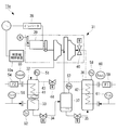
- FIG. 2 is a diagram showing a schematic configuration of the heat source devices 11a, 11b, and 11c. Since the configurations and functions of the heat source units 11a, 11b, and 11c are the same, in the following description, the heat source unit 11a will be described as an example.
- the heat source device 11a is, for example, a turbo chiller, and is condensed by a compressor 31 that compresses the refrigerant, a condenser 32 that condenses the high-temperature and high-pressure gas refrigerant compressed by the compressor 31, and the condenser 32.
- An evaporator 36 for evaporating the liquid refrigerant is provided as a main configuration.
- the compressor 31 is, for example, a centrifugal two-stage compressor, and is driven by an electric motor 39 whose rotational speed is controlled by an inverter 38.
- the output of the inverter 38 is controlled by the heat source machine control device 10a.
- the compressor 31 may be a fixed speed compressor having a constant rotation speed.
- An inlet guide vane (hereinafter referred to as “IGV”) 40 for controlling the flow rate of the suction refrigerant is provided at the refrigerant suction port of the compressor 31 so that the capacity of the heat source unit 11a can be controlled.
- the condenser 32 is provided with a pressure sensor 51 for measuring the refrigerant condensation pressure Pc.
- the output of the pressure sensor 51 is transmitted to the heat source machine control device 10a.
- the subcooler 33 is provided on the downstream side of the refrigerant flow of the condenser 32 so as to supercool the condensed refrigerant.
- a temperature sensor 52 for measuring the refrigerant temperature Ts after supercooling is provided.
- the condenser 32 and the subcooler 33 are inserted with a cooling heat transfer tube 41 for cooling them.
- the cooling water flow rate F2 is measured by a flow meter 54
- the cooling water outlet temperature Tcout is measured by a temperature sensor 55
- the cooling water inlet temperature Tcin is measured by a temperature sensor 56.
- the cooling water is led to the condenser 32 and the subcooler 33 again after being exhausted to the outside in a cooling tower (not shown).
- the liquid refrigerant from the subcooler 33 is expanded by the step-down expansion valve 34 and sent to the intercooler 37.
- the intercooler 37 is provided with a pressure sensor 57 for measuring the intermediate pressure Pm.
- the liquid refrigerant cooled by the intermediate cooler 37 is expanded by the low-pressure expansion valve 35 and sent to the evaporator 36.
- the evaporator 36 is provided with a pressure sensor 58 for measuring the evaporation pressure Pe.
- the evaporator 36 is inserted with a cold water heat transfer tube 42 for cooling the cold water supplied to the external load 3 (see FIG. 1).
- the cold water flow rate F1 is measured by a flow meter 59
- the cold water outlet temperature Tout is measured by a temperature sensor 60
- the cold water inlet temperature Tin is measured by a temperature sensor 61.
- a hot gas bypass pipe 43 is provided between the vapor phase portion of the condenser 32 and the vapor phase portion of the evaporator 36.
- a hot gas bypass valve 44 for controlling the flow rate of the refrigerant flowing in the hot gas bypass pipe 43 is provided. By adjusting the hot gas bypass flow rate by the hot gas bypass valve 44, it is possible to control the capacity of a very small region that is not sufficiently controlled by the IGV 40.
- the condenser 32 and the subcooler 33 are provided, heat exchange is performed with the cooling water exhausted to the outside by the refrigerant in the cooling tower, and the cooling water is warmed is described.
- an air heat exchanger may be arranged instead of the condenser 32 and the subcooler 33, and heat may be exchanged between the outside air and the refrigerant in the air heat exchanger.
- the heat source machine control device 10a is, for example, a computer, and exchanges information by communicating with a main storage device such as a CPU (Central Processing Unit), a RAM (Random Access Memory), an auxiliary storage device, and an external device. It has a communication device to perform.
- the auxiliary storage device is a computer-readable recording medium, such as a magnetic disk, a magneto-optical disk, a CD-ROM, a DVD-ROM, or a semiconductor memory.
- Various programs are stored in the auxiliary storage device, and various processes are realized by the CPU reading and executing the program from the auxiliary storage device to the main storage device.
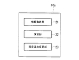
- FIG. 3 is a diagram illustrating an example of functional blocks of the heat source machine control device 10a illustrated in FIG.
- the heat source machine control device 10 a includes a data acquisition unit 21, a calculation unit 22, and a set temperature change unit 23.
- the data acquisition unit 21 uses various sensors such as the refrigerant condensing pressure Pc, the refrigerant temperature Ts, the cooling water flow rate F2, the cooling water outlet temperature Tcout, the cooling water inlet temperature Tcin, the chilled water flow rate F1, the chilled water outlet temperature Tout, and the chilled water inlet temperature Tin. Get the measured value.
- the calculation unit 22 calculates the load change rate (evaluation value regarding fluctuation) using the measurement value acquired by the data acquisition unit 21.
- the load change rate is calculated by the following equation (1), for example.
- Load change rate (A ⁇ (Qe (i) ⁇ Qe (i ⁇ 1)) + Qe (i ⁇ 1)) / Qe (i ⁇ 1) (1)
- A is the current load factor, a value obtained by dividing the current refrigeration capacity by the rated refrigeration capacity
- Qe (i) is the average heat exchange amount of the evaporator 36 in the past predetermined period from the present.
- Qe (i ⁇ 1) is an average of the heat exchange amount of the evaporator 36 in the past predetermined period from the previous sampling period.
- the heat exchange amount Qe of the evaporator 36 is obtained by the following equation (2).
- Tin is the cold water inlet temperature (° C.)
- Tout is the cold water outlet temperature (° C.)
- F 1 is the cold water flow rate (m 3 / s)
- ⁇ is the cold water density (kg / m 3 )
- c is the specific heat (kJ / kg). ° C).
- the past predetermined period can be set as appropriate according to the design, but is preferably set between 100 seconds and 140 seconds, for example. In this embodiment, it is set to 120 seconds.
- the set temperature changing unit 23 changes the chilled water outlet set temperature by a predetermined amount when the load change rate calculated by the calculation unit 22 exceeds a predetermined threshold.
- the predetermined amount is, for example, a temperature corresponding to about 10% of the difference between the cold water inlet temperature and the cold water outlet set temperature. For example, when the cold water inlet temperature is 12 ° C. and the cold water outlet set temperature is 7 ° C., 0.5% It becomes °C.
- the set temperature changing unit 23 decreases the chilled water outlet set temperature by a predetermined amount to increase the heat source machine load, and the load change rate is In the negative case, that is, when the chilled water outlet temperature tends to decrease, the chilled water outlet set temperature is increased by a predetermined amount to reduce the heat source machine load.
- various measurement values such as the refrigerant condensation pressure Pc are collected by the information acquisition unit 21, and the load change rate is calculated by the calculation unit 22.
- the set temperature changing unit 23 determines whether or not the load change rate calculated by the calculating unit 22 exceeds a predetermined threshold value. When the load temperature changing rate exceeds the threshold value, the set temperature changing unit 23 suppresses fluctuations in the chilled water outlet temperature. Increase or decrease the cold water outlet set temperature by a predetermined amount. In this way, by using the load change rate, it is possible to quickly detect a change in the chilled water outlet temperature and suppress overshoot in advance.
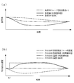
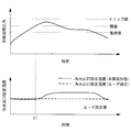
- FIG. 4 is a diagram illustrating the effects of the heat source device 11a and the control method thereof according to the present embodiment.
- the horizontal axis indicates time
- the vertical axis indicates the load factor
- the thin solid line indicates the load factor corresponding to the set outlet temperature
- the broken line indicates the load factor according to the conventional control method
- the thick solid line indicates the present embodiment. The load factor by this control method is shown.
- the horizontal axis indicates time
- the vertical axis indicates the cold water outlet temperature
- the thin solid line indicates the cold water outlet set temperature set by the user, in other words, the initial value of the cold water outlet set temperature (for example, 0 ° C.)
- the dotted line indicates the chilled water outlet set temperature according to the present embodiment
- the thick solid line indicates the chilled water outlet temperature according to the present embodiment
- the broken line indicates the chilled water outlet temperature according to the conventional control method.
- the conventional control method in which overshoot occurs may cause the heat medium to freeze, and cold water cannot be used as the heat medium.
- the heat source apparatus and the control method thereof according to the present embodiment it is possible to suppress the cold water outlet temperature from becoming 0 ° C. or less by suppressing overshoot. Thereby, it becomes possible to use cold water as a heat medium, and the heat exchange efficiency in the evaporator 36 can be improved.
- the chilled water outlet set temperature is changed when the load change rate exceeds the threshold.
- parameters that affect the chilled water outlet temperature for example, the chilled water inlet temperature Tin, the chilled water flow rate F1.
- Calculating the amount of change (evaluation value regarding the change) for each fixed period such as the cooling water inlet temperature Tcin, the cooling water flow rate F2, and changing the chilled water outlet set temperature when the amount of change exceeds a predetermined threshold It is good.
- the influence of noise can be reduced by calculating the fluctuation amount using the moving average value.
- the rate of change may be used instead of the amount of change.
- the load factor fluctuates due to this fluctuation.
- these parameters all affect the load factor.
- fluctuations in these parameters appear as fluctuations in the load factor. Therefore, by monitoring the load change rate, it is possible to efficiently grasp the state of the heat source unit.
- the case of cooling the cold water has been described.
- the heat medium for example, cold water or hot water
- the same control is performed to suppress the overshoot of the outlet temperature. It becomes possible.
- the heat source machine according to the present embodiment has different functions provided in the heat source machine control device.
- differences from the first embodiment will be mainly described, and description of common points will be omitted.
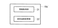
- FIG. 5 is a functional block diagram of the heat source machine control device 10a ′ according to the present embodiment.
- the heat source machine control device 10 a ′ includes an information acquisition unit 21 and a set temperature change unit 23 ′.
- the information acquisition unit 21 performs the refrigerant condensing pressure Pc, the refrigerant temperature Ts, the cooling water flow rate F2, the cooling water outlet temperature Tcout, the cooling water inlet temperature Tcin, the cooling water flow rate F1, the cooling water outlet temperature Tout, and the cooling water inlet temperature Tin.
- Etc the refrigerant condensing pressure Pc, the refrigerant temperature Ts, the cooling water flow rate F2, the cooling water outlet temperature Tcout, the cooling water inlet temperature Tcin, the cooling water flow rate F1, the cooling water outlet temperature Tout, and the cooling water inlet temperature Tin.
- the set temperature changing unit 23 ′ determines whether or not the refrigerant condensing pressure Pc exceeds a predetermined threshold among the various measurement values acquired by the information acquiring unit 21, and the refrigerant condensing pressure Pc exceeds the predetermined threshold. In this case, the cold water outlet set temperature is increased by a predetermined amount. An appropriate value may be set as appropriate for the increase width according to the design.
- the chilled water outlet set temperature is changed by a predetermined amount.
- the condensation pressure gradually decreases.
- the refrigerant condensing pressure becomes lower than a predetermined return value
- the cold water outlet set temperature may be returned to the initial value.
- the refrigerant condensing pressure is used, but the refrigerant condensing temperature may be used instead. In this case, when the refrigerant condensing temperature exceeds a predetermined threshold, the cold water outlet set temperature may be changed to a value higher by a predetermined amount.
Landscapes
- Engineering & Computer Science (AREA)
- Mechanical Engineering (AREA)
- General Engineering & Computer Science (AREA)
- Chemical & Material Sciences (AREA)
- Combustion & Propulsion (AREA)
- Physics & Mathematics (AREA)
- Thermal Sciences (AREA)
- Air Conditioning Control Device (AREA)
Abstract
熱媒の出口温度のオーバーシュートを抑制することを目的とする。熱源機制御装置(10a)は、演算部(22)と、設定温度変更部(23)とを備えている。演算部(22)は、所定の演算式を用いて負荷変化率を算出する。設定温度変更部(23)は、変動量算出部(22)によって算出された負荷変化率が所定の閾値を超えたか否かを判定し、超えた場合には、冷水出口温度の変化を抑制する方向に、冷水出口設定温度を変更する。たとえば、冷水出口温度が低下しつつある場合には、冷水出口設定温度が高めの値に設定されることで、熱源機の負荷が低下するとともに、冷水出口温度が変更後の冷水出口設定温度に一致するように制御される。これにより、オーバーシュートを抑制することが可能となる。
Description
本発明は、熱源機及びその制御方法に関するものである。
従来、圧縮機、凝縮器、及び蒸発器が配置された冷凍サイクルを有し、蒸発器に入力される冷水を所定の設定温度に冷却して出力するターボ冷凍機が知られている(例えば、特許文献1参照)。
一般的に、ターボ冷凍機に入力される冷水(熱媒)の温度や流量が大きく変動すると、制御が追従できず、冷水の出口温度にオーバーシュートが発生する場合がある。このオーバーシュートの発生は、ターボ冷凍機の運用上好ましいとはいえず、抑制する必要がある。このようなオーバーシュートは、熱媒を冷却する場合だけの問題ではなく、熱媒を加熱する場合にも同様に発生する。
特に、上記オーバーシュートは、冷水を冷却する場合であって、かつ、冷水の出口設定温度が0℃付近に設定されている場合に問題視される。すなわち、この場合にオーバーシュートが発生すると、冷水が0℃以下に冷やされ、最悪の場合、凍結に至るおそれがある。したがって、冷水の出口設定温度が0℃付近に設定されている場合には、熱媒に冷水を用いることはできず、不凍液(ブライン)が用いられていた。しかしながら、不凍液は、冷水に比べて熱交換器における熱交換効率が悪いため、熱交換の観点から熱媒として冷水を利用することが好ましい。
加えて、ターボ冷凍機などのように熱媒を冷却して外部負荷に出力する熱源機においては、以下のような問題がある。熱源機負荷が高く、かつ、外気温度が高い条件下においては、凝縮器において冷媒と熱交換する冷却水の排熱量が大きくなるため、冷却水を所望の温度まで低下させることができない可能性がある。この場合、冷媒凝縮圧力が上昇してしまい、場合によっては、熱源機を強制停止させなければならず、運転効率が低下する。
本発明は、このような事情に鑑みてなされたものであって、その目的の一つは、熱媒の出口温度のオーバーシュートを抑制することのできる熱源機及びその制御方法を提供することである。
本発明の他の目的は、熱源機負荷が高く、かつ、外気温度が高い条件下でも、熱源機の強制停止を回避することのできる熱源機及びその制御方法を提供することである。
本発明の他の目的は、熱源機負荷が高く、かつ、外気温度が高い条件下でも、熱源機の強制停止を回避することのできる熱源機及びその制御方法を提供することである。
本発明の第1態様は、圧縮機、第1熱交換器、及び第2熱交換器が配置されたヒートポンプサイクルを有し、前記第2熱交換器において、外部負荷から供給される熱媒と冷媒との間で熱交換させることにより、前記熱媒を所定の出口設定温度に冷却または加熱して該外部負荷へ供給する熱源機であって、前記熱媒の入口温度、前記熱媒の流量、前記第1熱交換器に供給される熱源の入口温度、前記熱源の流量、及び熱源機負荷率のうち、少なくともいずれか一つのパラメータについての変動に関する評価値を、予め保有している演算式を用いて算出する演算手段と、前記演算手段によって算出された評価値が所定の閾値を超えた場合に、前記熱媒の出口温度の変化を抑制する方向に、前記熱媒の出口設定温度を変更する設定温度変更手段とを具備する熱源機である。
本態様の熱源機によれば、熱媒を冷却して外部負荷に出力する場合には、第1熱交換器が凝縮器として、第2熱交換機が蒸発器として機能する。この場合において、熱媒の入口温度、熱媒の流量、第1熱交換器(凝縮器)に供給される熱源(冷却水)の入口温度、該熱源の流量、及び熱源機負荷率のうち、少なくともいずれか一つのパラメータの変動に関する評価値が、予め保有している演算式を用いて演算手段によって算出され、この評価値が所定の閾値を超えた場合に、オーバーシュートの兆しを検知し、設定温度変更手段により熱媒の出口設定温度が変更される。このとき、熱媒の出口設定温度は、熱媒の出口温度の変化を抑制する方向に変更されるので、熱媒の出口温度のオーバーシュートを抑制することが可能となる。
熱媒を加熱して外部負荷に出力する場合には、第1熱交換器が蒸発器として、第2熱交換機が凝縮器として機能する。この場合において、熱媒の入口温度、熱媒の流量、第1熱交換器(蒸発器)に供給される熱源(例えば、温水)の入口温度、該熱源の流量、及び熱源機負荷率のうち、少なくともいずれか一つのパラメータの変動に関する評価値が、所定の演算式を用いて演算手段によって算出され、この評価値が閾値を超えた場合に、オーバーシュートの兆しを検知し、設定温度変更手段により熱媒の出口設定温度が変更される。このとき、熱媒の出口設定温度は、熱媒の出口温度の変化を抑制する方向に変更されるので、熱媒の出口温度のオーバーシュートを抑制することが可能となる。
熱媒を加熱して外部負荷に出力する場合には、第1熱交換器が蒸発器として、第2熱交換機が凝縮器として機能する。この場合において、熱媒の入口温度、熱媒の流量、第1熱交換器(蒸発器)に供給される熱源(例えば、温水)の入口温度、該熱源の流量、及び熱源機負荷率のうち、少なくともいずれか一つのパラメータの変動に関する評価値が、所定の演算式を用いて演算手段によって算出され、この評価値が閾値を超えた場合に、オーバーシュートの兆しを検知し、設定温度変更手段により熱媒の出口設定温度が変更される。このとき、熱媒の出口設定温度は、熱媒の出口温度の変化を抑制する方向に変更されるので、熱媒の出口温度のオーバーシュートを抑制することが可能となる。
上記熱源機において、前記演算手段は、移動平均を用いて前記評価値を算出することとしてもよい。
移動平均を用いることにより、ノイズ成分を除去でき、オーバーシュートの兆しをより正確に検知することが可能となる。これにより、誤検知に起因して出口設定温度が無駄に変更されることを回避することが可能となる。
上記熱源機において、前記熱媒の出口設定温度の初期値は、0℃付近(例えば、0℃以上5℃以下)に設定されていてもよい。
本態様の熱源機によれば、上記のようにオーバーシュートを抑制するので、熱媒の出口設定温度の初期値が0℃付近に設定されている場合であっても、熱媒の出口温度が0℃以下に低下することを抑制することが可能となる。これにより、熱媒に冷水を用いることができ、不凍液を用いる場合と比べて、第2熱交換器における熱交換効率を向上させることが可能となる。
本発明の第2態様は、圧縮機、凝縮器、及び蒸発器が配置されたヒートポンプサイクルを有し、前記蒸発器において、外部負荷から供給される熱媒と冷媒との間で熱交換させることにより、前記熱媒を所定の出口設定温度に冷却して該外部負荷へ供給する熱源機であって、前記凝縮器における冷媒凝縮圧力または冷媒凝縮温度を取得する情報取得手段と、前記情報取得手段で取得された冷媒凝縮圧力または冷媒凝縮温度が所定の閾値を超えた場合に、前記熱媒の出口設定温度を上昇させる設定温度変更手段とを具備する熱源機である。
本態様の熱源機によれば、凝縮器における冷媒凝縮圧力または冷媒凝縮温度が所定の閾値を超えた場合に、熱媒の出口設定温度が上昇する方向に変更されるので、熱源機負荷を低下させることが可能となる。これにより、冷媒凝縮圧力または冷媒凝縮温度を低下させることが可能となり、冷媒凝縮圧力または冷媒凝縮温度が閾値を超えることによる熱源機の強制停止を回避することが可能となる。この結果、熱源機の運転効率の低下を抑制することが可能となる。
本発明の第3態様は、圧縮機、第1熱交換器、及び第2熱交換器が配置されたヒートポンプサイクルを有し、前記第2熱交換器において、外部負荷から供給される熱媒と冷媒との間で熱交換させることにより、前記熱媒を所定の出口設定温度に冷却または加熱して該外部負荷へ供給する熱源機の制御方法であって、前記熱媒の入口温度、前記熱媒の流量、前記第1熱交換器に供給される熱源の入口温度、前記熱源の流量、及び熱源機負荷率のうち、少なくともいずれか一つのパラメータについて、変動に関する評価値を予め保有している演算式を用いて算出する演算ステップと、前記演算ステップによって算出された評価値が所定の閾値を超えた場合に、前記熱媒の出口温度の変化を抑制する方向に、前記熱媒の出口設定温度を変更する設定温度変更ステップとを具備する熱源機の制御方法である。
本発明の第4態様は、圧縮機、凝縮器、及び蒸発器が配置されたヒートポンプサイクルを有し、前記蒸発器において、外部負荷から供給される熱媒と冷媒との間で熱交換させることにより、前記熱媒を所定の出口設定温度に冷却して該外部負荷へ供給する熱源機の制御方法であって、前記凝縮器における冷媒凝縮圧力または冷媒凝縮温度を取得する情報取得ステップと、前記情報取得ステップで取得された冷媒凝縮圧力または冷媒凝縮温度が所定の閾値を超えた場合に、前記熱媒の出口設定温度を上昇させる設定温度変更ステップとを具備する熱源機の制御方法である。
本発明によれば、熱媒の出口温度のオーバーシュートを抑制することがきる。これにより、例えば、熱媒の出口設定温度が0℃付近に設定されていた場合でも、熱媒として水を利用することが可能となり、熱交換器における熱効率を向上させることが可能となる。
本発明によれば、熱源機負荷が高く、かつ、外気温度が高い条件下でも、熱源機の強制停止を回避することができる。これにより、安定した熱源機運転を実現することが可能となる。
本発明によれば、熱源機負荷が高く、かつ、外気温度が高い条件下でも、熱源機の強制停止を回避することができる。これにより、安定した熱源機運転を実現することが可能となる。
〔第1実施形態〕
以下に、本発明の第1実施形態に係る熱源機及びその制御方法について、図面を参照して説明する。図1は、本発明の第1実施形態に係る熱源機が適用される熱源システム1の構成を概略的に示した図である。
以下に、本発明の第1実施形態に係る熱源機及びその制御方法について、図面を参照して説明する。図1は、本発明の第1実施形態に係る熱源機が適用される熱源システム1の構成を概略的に示した図である。
熱源システム1は、複数の熱源機11a、11b、11cを備えている。本実施形態では、説明の便宜上、熱源機11a、11b、11cが、空調機や給湯機、工場設備等の外部負荷3に対して供給する冷水(熱媒)を冷却する冷却装置として機能する場合について説明するが、本発明の熱源機11a、11b、11cは、例えば、冷水(熱媒)を加熱する加熱装置として機能してもよいし、冷却と加熱の両方の機能を兼ね備えていてもよい。
図1では、3台の熱源機11a、11b、11cが設置されている場合について例示しているが、熱源機の設置台数については任意に決定することができる。
図1では、3台の熱源機11a、11b、11cが設置されている場合について例示しているが、熱源機の設置台数については任意に決定することができる。
冷水流れからみた各熱源機11a、11b、11cの上流側には、それぞれ、冷水を圧送する冷水ポンプ12a、12b、12cが設置されている。これら冷水ポンプ12a、12b、12cによって、リターンヘッダ14からの冷水が各熱源機11a、11b、11cへと送られる。各冷水ポンプ12a、12b、12cは、インバータモータ(図示略)によって駆動されるようになっており、これにより、回転数を可変とすることで可変流量制御される。
サプライヘッダ13には、各熱源機11a、11b、11cにおいて得られた冷水が集められるようになっている。サプライヘッダ13に集められた冷水は、外部負荷3に供給される。外部負荷3にて空調等に供されて昇温した冷水は、リターンヘッダ14に送られる。冷水は、リターンヘッダ14において分岐され、各熱源機11a、11b、11cに送られる。
サプライヘッダ13とリターンヘッダ14との間にはバイパス配管18が設けられている。バイパス配管18に設けられたバイパス弁19の開度を調整することにより、外部負荷3へ供給する冷水量を調整することができる。
図2は、熱源機11a、11b、11cの概略構成を示した図である。熱源機11a、11b,11cの構成及び機能は同じであるため、以下の説明においては、熱源機11aを例示して説明する。
熱源機11aは、例えば、ターボ冷凍機であり、冷媒を圧縮する圧縮機31と、圧縮機31によって圧縮された高温高圧のガス冷媒を凝縮する凝縮器32と、凝縮器32にて凝縮された液冷媒を蒸発させる蒸発器36とを主な構成として備えている。
圧縮機31は、例えば、遠心式の2段圧縮機であり、インバータ38によって回転数制御された電動モータ39によって駆動されている。インバータ38は、熱源機制御装置10aによってその出力が制御されている。なお、圧縮機31は、回転数一定の固定速の圧縮機であってもよい。圧縮機31の冷媒吸入口には、吸入冷媒流量を制御するインレットガイドベーン(以下「IGV」という。)40が設けられており、熱源機11aの容量制御が可能となっている。
凝縮器32には、冷媒凝縮圧力Pcを計測するための圧力センサ51が設けられている。圧力センサ51の出力は、熱源機制御装置10aに送信される。
サブクーラ33は、凝縮器32の冷媒流れ下流側に、凝縮された冷媒に対して過冷却を与えるように設けられている。サブクーラ33の冷媒流れ下流側直後には、過冷却後の冷媒温度Tsを計測する温度センサ52が設けられている。
サブクーラ33は、凝縮器32の冷媒流れ下流側に、凝縮された冷媒に対して過冷却を与えるように設けられている。サブクーラ33の冷媒流れ下流側直後には、過冷却後の冷媒温度Tsを計測する温度センサ52が設けられている。
凝縮器32及びサブクーラ33には、これらを冷却するための冷却伝熱管41が挿通されている。冷却水流量F2は流量計54により、冷却水出口温度Tcoutは温度センサ55により、冷却水入口温度Tcinは温度センサ56により計測されるようになっている。冷却水は、図示しない冷却塔において外部へと排熱された後に、再び凝縮器32及びサブクーラ33へと導かれるようになっている。
サブクーラ33からの液冷媒は降圧膨張弁34により膨張され、中間冷却器37に送られる。中間冷却器37には、中間圧力Pmを計測するための圧力センサ57が設けられている。中間冷却器37により冷却された液冷媒は、低圧膨張弁35により膨張させられ、蒸発器36に送られる。蒸発器36には、蒸発圧力Peを計測するための圧力センサ58が設けられている。蒸発器36には、外部負荷3(図1参照)へ供給される冷水を冷却するための冷水伝熱管42が挿通されている。冷水流量F1は流量計59により、冷水出口温度Toutは温度センサ60により、冷水入口温度Tinは温度センサ61により計測されるようになっている。
凝縮器32の気相部と蒸発器36の気相部との間には、ホットガスバイパス管43が設けられている。そして、ホットガスバイパス管43内を流れる冷媒の流量を制御するためのホットガスバイパス弁44が設けられている。ホットガスバイパス弁44によってホットガスバイパス流量を調整することにより、IGV40では制御が十分でない非常に小さな領域の容量制御が可能となっている。
また、図2に示した熱源機11aでは、凝縮器32及びサブクーラ33を設け、冷媒により冷却塔において外部へと排熱した冷却水との間で熱交換を行い、冷却水を温める場合について述べたが、例えば、凝縮器32及びサブクーラ33に代えて空気熱交換器を配置し、空気熱交換器において外気と冷媒との間で熱交換を行うような構成としてもよい。
熱源機制御装置10aは、例えば、コンピュータであり、CPU(中央演算処理装置)、RAM(Random Access Memory)等の主記憶装置、補助記憶装置、外部の機器と通信を行うことにより情報の授受を行う通信装置などを備えている。
補助記憶装置は、コンピュータ読取可能な記録媒体であり、例えば、磁気ディスク、光磁気ディスク、CD-ROM、DVD-ROM、半導体メモリ等である。この補助記憶装置には、各種プログラムが格納されており、CPUが補助記憶装置から主記憶装置にプログラムを読み出し、実行することにより種々の処理を実現させる。
補助記憶装置は、コンピュータ読取可能な記録媒体であり、例えば、磁気ディスク、光磁気ディスク、CD-ROM、DVD-ROM、半導体メモリ等である。この補助記憶装置には、各種プログラムが格納されており、CPUが補助記憶装置から主記憶装置にプログラムを読み出し、実行することにより種々の処理を実現させる。
図3は、図2に示した熱源機制御装置10aの機能ブロックの一例を示した図である。図3に示すように、熱源機制御装置10aは、データ取得部21と、演算部22と、設定温度変更部23とを備えている。
データ取得部21は、冷媒凝縮圧力Pc、冷媒温度Ts、冷却水流量F2、冷却水出口温度Tcout、冷却水入口温度Tcin、冷水流量F1、冷水出口温度Tout、冷水入口温度Tin等、各種センサによって計測された計測値を取得する。
データ取得部21は、冷媒凝縮圧力Pc、冷媒温度Ts、冷却水流量F2、冷却水出口温度Tcout、冷却水入口温度Tcin、冷水流量F1、冷水出口温度Tout、冷水入口温度Tin等、各種センサによって計測された計測値を取得する。
演算部22は、データ取得部21によって取得された計測値を用いて、負荷変化率(変動に関する評価値)を算出する。負荷変化率は、例えば、以下の(1)式により算出される。
負荷変化率
=(A×(Qe(i)-Qe(i-1))+Qe(i-1))/Qe(i-1) (1)
=(A×(Qe(i)-Qe(i-1))+Qe(i-1))/Qe(i-1) (1)
上記(1)式において、Aは現在の負荷率であり、現在の冷凍能力を定格冷凍能力で除した値、Qe(i)は、現在から過去所定期間における蒸発器36の熱交換量の平均、Qe(i-1)は一つ前のサンプリング周期から過去所定期間における蒸発器36の熱交換量の平均である。ここで、蒸発器36の熱交換量Qeは、以下の(2)式で求められる。
Qe(kW)=(Tin-Tout)×F1×ρ×c (2)
ここで、Tinは冷水入口温度(℃)、Toutは冷水出口温度(℃)、F1は冷水流量(m3/s)、ρは冷水密度(kg/m3)、cは比熱(kJ/kg℃)である。
このように、移動平均を用いることにより、値を平滑化することが可能となる。上記過去所定期間は、設計により適宜設定可能であるが、例えば、100秒から140秒の間で設定されることが好ましい。本実施形態では、120秒に設定されている。
このように、移動平均を用いることにより、値を平滑化することが可能となる。上記過去所定期間は、設計により適宜設定可能であるが、例えば、100秒から140秒の間で設定されることが好ましい。本実施形態では、120秒に設定されている。
設定温度変更部23は、演算部22によって算出された負荷変化率が所定の閾値を超えた場合に、冷水出口設定温度を所定量変更する。所定量は、例えば、冷水入口温度と冷水出口設定温度との差の10%程度に相当する温度であり、例えば、冷水入口温度が12℃、冷水出口設定温度が7℃の場合、0.5℃となる。
設定温度変更部23は、負荷変化率がプラスの場合、すなわち、冷水出口温度が上昇傾向にある場合には冷水出口設定温度を所定量低くして、熱源機負荷を増加させ、負荷変化率がマイナスの場合、すなわち、冷水出口温度が下降傾向にある場合には冷水出口設定温度を所定量高くして、熱源機負荷を低下させる。
設定温度変更部23は、負荷変化率がプラスの場合、すなわち、冷水出口温度が上昇傾向にある場合には冷水出口設定温度を所定量低くして、熱源機負荷を増加させ、負荷変化率がマイナスの場合、すなわち、冷水出口温度が下降傾向にある場合には冷水出口設定温度を所定量高くして、熱源機負荷を低下させる。
このような熱源機制御装置10aによれば、情報取得部21によって冷媒凝縮圧力Pc等の各種計測値が収集され、演算部22によって負荷変化率の演算が行われる。設定温度変更部23は、演算部22によって演算された負荷変化率が所定の閾値を超えているか否かを判定し、閾値を超えていた場合に、冷水出口温度の変動を抑制する方向に、冷水出口設定温度を所定量増減させる。このように、負荷変化率を用いることで、冷水出口温度の変動を速やかに察知し、オーバーシュートを未然に抑制することが可能となる。
図4は、本実施形態に係る熱源機11a及びその制御方法の効果を示した図である。図4(a)において、横軸は時間、縦軸は負荷率を示しており、細実線は設定出口温度見合いの負荷率、破線は従来の制御方法による負荷率、太実線は本実施形態に係る制御方法による負荷率を示している。
図4(b)において、横軸は時間、縦軸は冷水出口温度を示しており、細実線は使用者によって設定された冷水出口設定温度、換言すると、冷水出口設定温度の初期値(例えば、0℃)、点線は本実施形態に係る冷水出口設定温度、太実線は本実施形態に係る冷水出口温度、破線は従来の制御方法による冷水出口温度を示している。
図4(b)において、横軸は時間、縦軸は冷水出口温度を示しており、細実線は使用者によって設定された冷水出口設定温度、換言すると、冷水出口設定温度の初期値(例えば、0℃)、点線は本実施形態に係る冷水出口設定温度、太実線は本実施形態に係る冷水出口温度、破線は従来の制御方法による冷水出口温度を示している。
図4に示すように、従来の制御方法では、冷水流量が低下するなどの何らかの要因により、負荷率が低下すると、この変化に速やかに追従できず、冷水出口温度にオーバーシュートが発生する(図4(b)の破線参照)。これに対し、本実施形態に係る制御方法では、負荷変化率により負荷率の変化をモニタしており、負荷変化率が閾値を超えた場合は、冷水出口設定温度が変更される(図4(b)の時刻t1における点線参照)。冷水出口設定温度が変更されると、変更後の冷水出口設定温度に出口温度が一致するような制御が実施されることから、負荷率は下がり(図4(a)の太実線参照)、また、冷水出口温度も冷水出口設定温度に次第に近づく(図4(b)の太実線参照)。
これにより、従来の制御方法に比べてオーバーシュートを抑制することが可能となる。特に、冷水出口温度が0℃付近に設定されていた場合には、オーバーシュートが発生する従来の制御方法では、熱媒が凍結するおそれがあり、熱媒に冷水を用いることはできない。これに対し、本実施形態に係る熱源機及びその制御方法によれば、オーバーシュートを抑制することにより、冷水出口温度が0℃以下となることを抑制することが可能となる。これにより、熱媒として冷水を用いることが可能となり、蒸発器36における熱交換効率を高めることができる。
なお、本実施形態では、負荷変化率が閾値を超えた場合に冷水出口設定温度を変更することとしたが、例えば、冷水出口温度に影響を与えるパラメータ、例えば、冷水入口温度Tin、冷水流量F1、冷却水入口温度Tcin、冷却水流量F2などの一定期間毎の変化量(変動に関する評価値)を算出し、この変化量が所定の閾値を超えた場合に、冷水出口設定温度を変更することとしてもよい。この場合、上述したように、移動平均値を用いて変動量を算出することで、ノイズによる影響を低減することができる。なお、変動量に変えて、変化率を用いてもよい。要は、上記パラメータの変動を感知するような評価値を演算すればよく、その評価関数については、特に限定されない。
ここで、上記冷水入口温度等の各種パラメータが変動した場合、この変動に起因して負荷率が変動する。換言すると、これらパラメータはいずれも負荷率に影響を及ぼすものである。このように、これらパラメータの変動は、負荷率の変動として現れるため、負荷変化率をモニタすれば、効率的に熱源機の状況を把握することができる。
また、本実施形態においては、冷水を冷却する場合について述べたが、熱媒(例えば、冷水または温水等)を加熱する場合においても同様の制御を行うことにより、出口温度のオーバーシュートを抑制することが可能となる。
〔第2実施形態〕
次に、本発明の第2実施形態に係る熱源機及びその制御方法について説明する。本実施形態に係る熱源機は、熱源機制御装置が備える機能が異なる。以下、第1実施形態と異なる点について主に説明し、共通の点については説明を省略する。
次に、本発明の第2実施形態に係る熱源機及びその制御方法について説明する。本実施形態に係る熱源機は、熱源機制御装置が備える機能が異なる。以下、第1実施形態と異なる点について主に説明し、共通の点については説明を省略する。
図5は、本実施形態に係る熱源機制御装置10a´の機能ブロック図である。図5に示すように、熱源機制御装置10a´は、情報取得部21及び設定温度変更部23´を備えている。
情報取得部21は、上述したように、冷媒凝縮圧力Pc、冷媒温度Ts、冷却水流量F2、冷却水出口温度Tcout、冷却水入口温度Tcin、冷水流量F1、冷水出口温度Tout、冷水入口温度Tin等を取得する。
設定温度変更部23´は、情報取得部21によって取得された各種計測値のうち、冷媒凝縮圧力Pcが所定の閾値を超えたか否かを判定し、冷媒凝縮圧力Pcが所定の閾値を超えた場合に、冷水出口設定温度を所定量上昇させる。この上昇幅は、設計により適宜適切な値を設定すればよい。
情報取得部21は、上述したように、冷媒凝縮圧力Pc、冷媒温度Ts、冷却水流量F2、冷却水出口温度Tcout、冷却水入口温度Tcin、冷水流量F1、冷水出口温度Tout、冷水入口温度Tin等を取得する。
設定温度変更部23´は、情報取得部21によって取得された各種計測値のうち、冷媒凝縮圧力Pcが所定の閾値を超えたか否かを判定し、冷媒凝縮圧力Pcが所定の閾値を超えた場合に、冷水出口設定温度を所定量上昇させる。この上昇幅は、設計により適宜適切な値を設定すればよい。
このような熱源機によれば、図6に示すように、凝縮器の冷媒凝縮圧力Pcが所定の閾値を超えた場合に(時刻t1参照)、冷水出口設定温度が所定量高く変更される。冷水出口設定温度が高めに設定されることで、凝縮圧力は徐々に低下する。これにより、熱源機負荷が高く、かつ、外気温度が高い条件下でも、熱源機の強制停止を回避することが可能となる。また、冷媒凝縮圧力が所定の復帰値よりも低くなった場合に、冷水出口設定温度を初期値に戻すこととしてもよい。
また、本実施形態においては、冷媒凝縮圧力を用いたが、これに代えて、冷媒凝縮温度を用いることとしてもよい。この場合、冷媒凝縮温度が所定の閾値を超えた場合に、冷水出口設定温度を所定量高い値に変更すればよい。
また、本実施形態においては、冷媒凝縮圧力を用いたが、これに代えて、冷媒凝縮温度を用いることとしてもよい。この場合、冷媒凝縮温度が所定の閾値を超えた場合に、冷水出口設定温度を所定量高い値に変更すればよい。
本発明は、上述の実施形態のみに限定されるものではなく、発明の要旨を逸脱しない範囲において、例えば、上述した各実施形態を部分的または全体的に組み合わせる等して、種々変形実施が可能である。
1 熱源システム
3 外部負荷
10a、10a´ 熱源機制御装置
11a、11b、11c 熱源機
21 情報取得部
22 演算部
23、23´ 設定温度変更部
31 圧縮機
32 凝縮器
36 蒸発器
3 外部負荷
10a、10a´ 熱源機制御装置
11a、11b、11c 熱源機
21 情報取得部
22 演算部
23、23´ 設定温度変更部
31 圧縮機
32 凝縮器
36 蒸発器
Claims (6)
- 圧縮機、第1熱交換器、及び第2熱交換器が配置されたヒートポンプサイクルを有し、前記第2熱交換器において、外部負荷から供給される熱媒と冷媒との間で熱交換させることにより、前記熱媒を所定の出口設定温度に冷却または加熱して該外部負荷へ供給する熱源機であって、
前記熱媒の入口温度、前記熱媒の流量、前記第1熱交換器に供給される熱源の入口温度、前記熱源の流量、及び熱源機負荷率のうち、少なくともいずれか一つのパラメータについての変動に関する評価値を、予め保有している演算式を用いて算出する演算手段と、
前記演算手段によって算出された評価値が所定の閾値を超えた場合に、前記熱媒の出口温度の変化を抑制する方向に、前記熱媒の出口設定温度を変更する設定温度変更手段と
を具備する熱源機。 - 前記演算手段は、移動平均を用いて前記評価値を算出する請求項1に記載の熱源機。
- 前記熱媒の出口設定温度の初期値は、0℃付近に設定されている請求項1または請求項2に記載の熱源機。
- 圧縮機、凝縮器、及び蒸発器が配置されたヒートポンプサイクルを有し、前記蒸発器において、外部負荷から供給される熱媒と冷媒との間で熱交換させることにより、前記熱媒を所定の出口設定温度に冷却して該外部負荷へ供給する熱源機であって、
前記凝縮器における冷媒凝縮圧力または冷媒凝縮温度を取得する情報取得手段と、
前記情報取得手段で取得された冷媒凝縮圧力または冷媒凝縮温度が所定の閾値を超えた場合に、前記熱媒の出口設定温度を上昇させる設定温度変更手段と
を具備する熱源機。 - 圧縮機、第1熱交換器、及び第2熱交換器が配置されたヒートポンプサイクルを有し、前記第2熱交換器において、外部負荷から供給される熱媒と冷媒との間で熱交換させることにより、前記熱媒を所定の出口設定温度に冷却または加熱して該外部負荷へ供給する熱源機の制御方法であって、
前記熱媒の入口温度、前記熱媒の流量、前記第1熱交換器に供給される熱源の入口温度、前記熱源の流量、及び熱源機負荷率のうち、少なくともいずれか一つのパラメータについての変動に関する評価値を、予め保有している演算式を用いて算出する演算ステップと、
前記演算ステップによって算出された評価値が所定の閾値を超えた場合に、前記熱媒の出口温度の変化を抑制する方向に、前記熱媒の出口設定温度を変更する設定温度変更ステップと
を具備する熱源機の制御方法。 - 圧縮機、凝縮器、及び蒸発器が配置されたヒートポンプサイクルを有し、前記蒸発器において、外部負荷から供給される熱媒と冷媒との間で熱交換させることにより、前記熱媒を所定の出口設定温度に冷却して該外部負荷へ供給する熱源機の制御方法であって、
前記凝縮器における冷媒凝縮圧力または冷媒凝縮温度を取得する情報取得ステップと、
前記情報取得ステップで取得された冷媒凝縮圧力または冷媒凝縮温度が所定の閾値を超えた場合に、前記熱媒の出口設定温度を上昇させる設定温度変更ステップと
を具備する熱源機の制御方法。
Priority Applications (3)
| Application Number | Priority Date | Filing Date | Title |
|---|---|---|---|
| CN201480053030.7A CN105593611B (zh) | 2013-11-13 | 2014-11-05 | 热源机及其控制方法 |
| EP14863022.1A EP3037745B1 (en) | 2013-11-13 | 2014-11-05 | Heat source device and method for controlling same |
| US15/024,616 US10174986B2 (en) | 2013-11-13 | 2014-11-05 | Heat source machine and control method therefor |
Applications Claiming Priority (2)
| Application Number | Priority Date | Filing Date | Title |
|---|---|---|---|
| JP2013235264A JP6324707B2 (ja) | 2013-11-13 | 2013-11-13 | 熱源機及びその制御方法 |
| JP2013-235264 | 2013-11-13 |
Publications (1)
| Publication Number | Publication Date |
|---|---|
| WO2015072376A1 true WO2015072376A1 (ja) | 2015-05-21 |
Family
ID=53057312
Family Applications (1)
| Application Number | Title | Priority Date | Filing Date |
|---|---|---|---|
| PCT/JP2014/079324 Ceased WO2015072376A1 (ja) | 2013-11-13 | 2014-11-05 | 熱源機及びその制御方法 |
Country Status (5)
| Country | Link |
|---|---|
| US (1) | US10174986B2 (ja) |
| EP (1) | EP3037745B1 (ja) |
| JP (1) | JP6324707B2 (ja) |
| CN (1) | CN105593611B (ja) |
| WO (1) | WO2015072376A1 (ja) |
Families Citing this family (19)
| Publication number | Priority date | Publication date | Assignee | Title |
|---|---|---|---|---|
| JP6433709B2 (ja) * | 2014-07-30 | 2018-12-05 | 三菱重工サーマルシステムズ株式会社 | ターボ冷凍機及びその制御装置並びにその制御方法 |
| JP6716306B2 (ja) * | 2016-03-23 | 2020-07-01 | 三菱重工サーマルシステムズ株式会社 | 熱源システムの設定温度制御装置、及びそれを備えた熱源システム、並びに熱源システムの設定温度制御方法 |
| CN106546020B (zh) * | 2016-10-27 | 2018-04-06 | 重庆美的通用制冷设备有限公司 | 空调系统 |
| JP6890021B2 (ja) * | 2017-02-28 | 2021-06-18 | 三菱重工サーマルシステムズ株式会社 | ターボ冷凍機、及びターボ冷凍機の運転方法 |
| JP6835651B2 (ja) * | 2017-03-31 | 2021-02-24 | 三菱重工サーマルシステムズ株式会社 | 冷凍機制御装置、ターボ冷凍機、冷凍機制御方法およびプログラム |
| JP7017406B2 (ja) * | 2017-12-27 | 2022-02-08 | 三菱重工サーマルシステムズ株式会社 | 制御装置、冷凍機システム、制御方法及びプログラム |
| IT201800001070A1 (it) * | 2018-01-16 | 2019-07-16 | Meno Energia S R L | Metodo e dispositivo per la produzione di acqua refrigerata |
| DE102018205415A1 (de) * | 2018-04-11 | 2019-10-17 | Robert Bosch Gmbh | Hvac-system und verfahren zum betreiben eines hvac-systems |
| JP7235460B2 (ja) * | 2018-09-13 | 2023-03-08 | 三菱重工サーマルシステムズ株式会社 | 制御装置、熱源システム、冷却水入口温度下限値の算出方法、制御方法およびプログラム |
| CN115790233A (zh) * | 2018-10-05 | 2023-03-14 | 塞阿姆斯特朗有限公司 | 传热系统的前馈流量控制 |
| EP4230924A3 (en) * | 2019-06-03 | 2023-10-18 | Daikin Industries, Ltd. | Device management apparatus and heat source system |
| CN113028729B (zh) * | 2021-03-30 | 2022-05-10 | 长虹美菱股份有限公司 | 一种冰箱制冷控制方法 |
| CN113418283B (zh) * | 2021-05-14 | 2022-12-13 | 青岛海尔空调电子有限公司 | 用于空调器的控制方法 |
| CN113654134B (zh) * | 2021-07-30 | 2023-05-26 | 青岛海尔空调电子有限公司 | 冷水机组的控制方法 |
| CN114118465A (zh) * | 2021-11-12 | 2022-03-01 | 北京金茂绿建科技有限公司 | 一种溶液的防冻控制方法、装置、电子设备及存储装置 |
| WO2023195125A1 (ja) * | 2022-04-07 | 2023-10-12 | 三菱電機株式会社 | 冷凍サイクルシステム |
| CN115682572B (zh) * | 2022-11-07 | 2024-08-16 | 珠海格力电器股份有限公司 | 冷冻水机组负荷确定、加卸载控制方法、装置及设备 |
| CN118939034B (zh) * | 2024-08-09 | 2026-03-27 | 北京京仪自动化装备技术股份有限公司 | 温控设备及温控方法 |
| CN118960264B (zh) * | 2024-09-19 | 2025-10-31 | 广东派沃新能源科技有限公司 | 一种热泵的制冷防冻控制方法 |
Citations (10)
| Publication number | Priority date | Publication date | Assignee | Title |
|---|---|---|---|---|
| JPS63129250A (ja) * | 1986-11-18 | 1988-06-01 | 三洋電機株式会社 | 空気調和機の保護装置 |
| JPH03236580A (ja) * | 1990-02-13 | 1991-10-22 | Yanmar Diesel Engine Co Ltd | 冷凍機の制御機構 |
| JPH1089783A (ja) * | 1996-09-12 | 1998-04-10 | Sanyo Electric Co Ltd | 冷凍機 |
| JP2002061925A (ja) * | 2000-08-23 | 2002-02-28 | Daikin Ind Ltd | 空気調和装置 |
| US6688124B1 (en) * | 2002-11-07 | 2004-02-10 | Carrier Corporation | Electronic expansion valve control for a refrigerant cooled variable frequency drive (VFD) |
| JP2005016872A (ja) * | 2003-06-27 | 2005-01-20 | Matsushita Electric Ind Co Ltd | 冷凍冷蔵ユニットおよび冷蔵庫 |
| JP2007046857A (ja) * | 2005-08-11 | 2007-02-22 | Yamatake Corp | 運転台数制御装置および方法 |
| JP2007147094A (ja) * | 2005-11-24 | 2007-06-14 | Shin Nippon Air Technol Co Ltd | 空気調和設備の運転方法 |
| JP2008002765A (ja) * | 2006-06-23 | 2008-01-10 | Hitachi Appliances Inc | 熱源装置 |
| JP2013160440A (ja) | 2012-02-06 | 2013-08-19 | Hitachi Appliances Inc | ターボ冷凍機 |
Family Cites Families (13)
| Publication number | Priority date | Publication date | Assignee | Title |
|---|---|---|---|---|
| US6145751A (en) * | 1999-01-12 | 2000-11-14 | Siemens Building Technologies, Inc. | Method and apparatus for determining a thermal setpoint in a HVAC system |
| US6085532A (en) * | 1999-02-05 | 2000-07-11 | American Standard Inc. | Chiller capacity control with variable chilled water flow compensation |
| JP3236580B2 (ja) | 1999-06-08 | 2001-12-10 | 鹿島建設株式会社 | シールド機、シールド機の掘進方法および斜坑または立坑の構築方法 |
| TW505770B (en) * | 2000-05-02 | 2002-10-11 | Nishiyama Corp | Temperature controller |
| JP3504608B2 (ja) * | 2000-12-06 | 2004-03-08 | イノテック株式会社 | 冷却システム |
| ITGE20020028A1 (it) * | 2002-04-10 | 2003-10-10 | Carpigiani Group Ali Spa | Metodo ed apparato di regolazione della portata di fluido refrigerante in macchine per la produzione di gelato. |
| JP2006153429A (ja) * | 2004-10-25 | 2006-06-15 | Nuflare Technology Inc | 恒温流体供給システム |
| JP4910163B2 (ja) * | 2005-09-30 | 2012-04-04 | Smc株式会社 | 恒温液循環装置及び該装置における温度制御方法 |
| US20080006044A1 (en) * | 2006-07-10 | 2008-01-10 | Ziming Tan | Method for controlling temperature |
| JP2012141098A (ja) * | 2010-12-28 | 2012-07-26 | Mitsubishi Heavy Ind Ltd | 熱源システムおよびその制御方法 |
| JP2013164223A (ja) * | 2012-02-13 | 2013-08-22 | Hitachi Appliances Inc | 熱源システム |
| JP5787792B2 (ja) | 2012-02-29 | 2015-09-30 | 三菱重工業株式会社 | 熱源システムの台数制御装置及びその方法並びに熱源システム |
| CN104220822B (zh) | 2012-04-30 | 2016-08-24 | 江森自控科技公司 | 控制系统 |
-
2013
- 2013-11-13 JP JP2013235264A patent/JP6324707B2/ja active Active
-
2014
- 2014-11-05 WO PCT/JP2014/079324 patent/WO2015072376A1/ja not_active Ceased
- 2014-11-05 US US15/024,616 patent/US10174986B2/en active Active
- 2014-11-05 EP EP14863022.1A patent/EP3037745B1/en active Active
- 2014-11-05 CN CN201480053030.7A patent/CN105593611B/zh active Active
Patent Citations (10)
| Publication number | Priority date | Publication date | Assignee | Title |
|---|---|---|---|---|
| JPS63129250A (ja) * | 1986-11-18 | 1988-06-01 | 三洋電機株式会社 | 空気調和機の保護装置 |
| JPH03236580A (ja) * | 1990-02-13 | 1991-10-22 | Yanmar Diesel Engine Co Ltd | 冷凍機の制御機構 |
| JPH1089783A (ja) * | 1996-09-12 | 1998-04-10 | Sanyo Electric Co Ltd | 冷凍機 |
| JP2002061925A (ja) * | 2000-08-23 | 2002-02-28 | Daikin Ind Ltd | 空気調和装置 |
| US6688124B1 (en) * | 2002-11-07 | 2004-02-10 | Carrier Corporation | Electronic expansion valve control for a refrigerant cooled variable frequency drive (VFD) |
| JP2005016872A (ja) * | 2003-06-27 | 2005-01-20 | Matsushita Electric Ind Co Ltd | 冷凍冷蔵ユニットおよび冷蔵庫 |
| JP2007046857A (ja) * | 2005-08-11 | 2007-02-22 | Yamatake Corp | 運転台数制御装置および方法 |
| JP2007147094A (ja) * | 2005-11-24 | 2007-06-14 | Shin Nippon Air Technol Co Ltd | 空気調和設備の運転方法 |
| JP2008002765A (ja) * | 2006-06-23 | 2008-01-10 | Hitachi Appliances Inc | 熱源装置 |
| JP2013160440A (ja) | 2012-02-06 | 2013-08-19 | Hitachi Appliances Inc | ターボ冷凍機 |
Non-Patent Citations (1)
| Title |
|---|
| See also references of EP3037745A4 |
Also Published As
| Publication number | Publication date |
|---|---|
| US20160216024A1 (en) | 2016-07-28 |
| JP6324707B2 (ja) | 2018-05-16 |
| CN105593611A (zh) | 2016-05-18 |
| JP2015094560A (ja) | 2015-05-18 |
| EP3037745A1 (en) | 2016-06-29 |
| EP3037745A4 (en) | 2017-03-08 |
| EP3037745B1 (en) | 2021-08-11 |
| US10174986B2 (en) | 2019-01-08 |
| CN105593611B (zh) | 2018-05-25 |
Similar Documents
| Publication | Publication Date | Title |
|---|---|---|
| JP6324707B2 (ja) | 熱源機及びその制御方法 | |
| JP5761960B2 (ja) | 熱源装置 | |
| CN101646911B (zh) | 使风冷式冷却器系统以最优能量效率比运行的方法 | |
| US8812263B2 (en) | Centrifugal chiller performance evaluation system | |
| JP5984703B2 (ja) | 熱源システム及び冷却水供給装置の制御装置並びに制御方法 | |
| JP5427563B2 (ja) | インバータターボ冷凍機の性能評価装置 | |
| KR101242385B1 (ko) | 히트 펌프 및 히트 펌프의 열매체 유량 연산 방법 | |
| EP2821725B1 (en) | A heat source system having a number-of-machines control device, method therefor | |
| JP5812653B2 (ja) | 熱媒流量推定装置、熱源機、及び熱媒流量推定方法 | |
| JP5554277B2 (ja) | 熱媒流量推定装置、熱源機、及び熱媒流量推定方法 | |
| EP2693136A1 (en) | Expansion valve control device, heat source machine, and expansion valve control method | |
| JP2009204262A (ja) | ターボ冷凍機および熱源システムならびにこれらの制御方法 | |
| CN103673441B (zh) | 并联型制冷机的控制装置及方法 | |
| JP2012052733A (ja) | ターボ冷凍機の性能評価装置 | |
| JP2012141098A (ja) | 熱源システムおよびその制御方法 | |
| JP5931774B2 (ja) | ターボ冷凍機の最大負荷率算出装置及びその方法並びに熱源システム及びその台数制御方法 | |
| JP6855160B2 (ja) | 熱源システムの台数制御装置及びその方法並びに熱源システム | |
| JP6219160B2 (ja) | ターボ冷凍機の最大負荷率算出装置及びその方法並びに熱源システム及びその台数制御方法 |
Legal Events
| Date | Code | Title | Description |
|---|---|---|---|
| 121 | Ep: the epo has been informed by wipo that ep was designated in this application |
Ref document number: 14863022 Country of ref document: EP Kind code of ref document: A1 |
|
| WWE | Wipo information: entry into national phase |
Ref document number: 2014863022 Country of ref document: EP |
|
| WWE | Wipo information: entry into national phase |
Ref document number: 15024616 Country of ref document: US |
|
| NENP | Non-entry into the national phase |
Ref country code: DE |