WO2015072436A1 - 受電装置 - Google Patents
受電装置 Download PDFInfo
- Publication number
- WO2015072436A1 WO2015072436A1 PCT/JP2014/079794 JP2014079794W WO2015072436A1 WO 2015072436 A1 WO2015072436 A1 WO 2015072436A1 JP 2014079794 W JP2014079794 W JP 2014079794W WO 2015072436 A1 WO2015072436 A1 WO 2015072436A1
- Authority
- WO
- WIPO (PCT)
- Prior art keywords
- coil
- power receiving
- core
- receiving device
- power
- Prior art date
- Legal status (The legal status is an assumption and is not a legal conclusion. Google has not performed a legal analysis and makes no representation as to the accuracy of the status listed.)
- Ceased
Links
Images





Classifications
-
- B—PERFORMING OPERATIONS; TRANSPORTING
- B60—VEHICLES IN GENERAL
- B60L—PROPULSION OF ELECTRICALLY-PROPELLED VEHICLES; SUPPLYING ELECTRIC POWER FOR AUXILIARY EQUIPMENT OF ELECTRICALLY-PROPELLED VEHICLES; ELECTRODYNAMIC BRAKE SYSTEMS FOR VEHICLES IN GENERAL; MAGNETIC SUSPENSION OR LEVITATION FOR VEHICLES; MONITORING OPERATING VARIABLES OF ELECTRICALLY-PROPELLED VEHICLES; ELECTRIC SAFETY DEVICES FOR ELECTRICALLY-PROPELLED VEHICLES
- B60L53/00—Methods of charging batteries, specially adapted for electric vehicles; Charging stations or on-board charging equipment therefor; Exchange of energy storage elements in electric vehicles
- B60L53/10—Methods of charging batteries, specially adapted for electric vehicles; Charging stations or on-board charging equipment therefor; Exchange of energy storage elements in electric vehicles characterised by the energy transfer between the charging station and the vehicle
- B60L53/12—Inductive energy transfer
-
- B—PERFORMING OPERATIONS; TRANSPORTING
- B60—VEHICLES IN GENERAL
- B60K—ARRANGEMENT OR MOUNTING OF PROPULSION UNITS OR OF TRANSMISSIONS IN VEHICLES; ARRANGEMENT OR MOUNTING OF PLURAL DIVERSE PRIME-MOVERS IN VEHICLES; AUXILIARY DRIVES FOR VEHICLES; INSTRUMENTATION OR DASHBOARDS FOR VEHICLES; ARRANGEMENTS IN CONNECTION WITH COOLING, AIR INTAKE, GAS EXHAUST OR FUEL SUPPLY OF PROPULSION UNITS IN VEHICLES
- B60K1/00—Arrangement or mounting of electrical propulsion units
- B60K1/04—Arrangement or mounting of electrical propulsion units of the electric storage means for propulsion
-
- B—PERFORMING OPERATIONS; TRANSPORTING
- B60—VEHICLES IN GENERAL
- B60L—PROPULSION OF ELECTRICALLY-PROPELLED VEHICLES; SUPPLYING ELECTRIC POWER FOR AUXILIARY EQUIPMENT OF ELECTRICALLY-PROPELLED VEHICLES; ELECTRODYNAMIC BRAKE SYSTEMS FOR VEHICLES IN GENERAL; MAGNETIC SUSPENSION OR LEVITATION FOR VEHICLES; MONITORING OPERATING VARIABLES OF ELECTRICALLY-PROPELLED VEHICLES; ELECTRIC SAFETY DEVICES FOR ELECTRICALLY-PROPELLED VEHICLES
- B60L5/00—Current collectors for power supply lines of electrically-propelled vehicles
-
- H—ELECTRICITY
- H01—ELECTRIC ELEMENTS
- H01F—MAGNETS; INDUCTANCES; TRANSFORMERS; SELECTION OF MATERIALS FOR THEIR MAGNETIC PROPERTIES
- H01F27/00—Details of transformers or inductances, in general
- H01F27/28—Coils; Windings; Conductive connections
- H01F27/2847—Sheets; Strips
-
- H—ELECTRICITY
- H01—ELECTRIC ELEMENTS
- H01F—MAGNETS; INDUCTANCES; TRANSFORMERS; SELECTION OF MATERIALS FOR THEIR MAGNETIC PROPERTIES
- H01F38/00—Adaptations of transformers or inductances for specific applications or functions
- H01F38/14—Inductive couplings
-
- H—ELECTRICITY
- H02—GENERATION; CONVERSION OR DISTRIBUTION OF ELECTRIC POWER
- H02J—ELECTRIC POWER NETWORKS; CIRCUIT ARRANGEMENTS OR SYSTEMS FOR SUPPLYING OR DISTRIBUTING ELECTRIC POWER; SYSTEMS FOR STORING ELECTRIC ENERGY
- H02J50/00—Circuit arrangements or systems for wireless supply or distribution of electric power
- H02J50/10—Circuit arrangements or systems for wireless supply or distribution of electric power using inductive coupling
-
- Y—GENERAL TAGGING OF NEW TECHNOLOGICAL DEVELOPMENTS; GENERAL TAGGING OF CROSS-SECTIONAL TECHNOLOGIES SPANNING OVER SEVERAL SECTIONS OF THE IPC; TECHNICAL SUBJECTS COVERED BY FORMER USPC CROSS-REFERENCE ART COLLECTIONS [XRACs] AND DIGESTS
- Y02—TECHNOLOGIES OR APPLICATIONS FOR MITIGATION OR ADAPTATION AGAINST CLIMATE CHANGE
- Y02T—CLIMATE CHANGE MITIGATION TECHNOLOGIES RELATED TO TRANSPORTATION
- Y02T10/00—Road transport of goods or passengers
- Y02T10/60—Other road transportation technologies with climate change mitigation effect
- Y02T10/70—Energy storage systems for electromobility, e.g. batteries
-
- Y—GENERAL TAGGING OF NEW TECHNOLOGICAL DEVELOPMENTS; GENERAL TAGGING OF CROSS-SECTIONAL TECHNOLOGIES SPANNING OVER SEVERAL SECTIONS OF THE IPC; TECHNICAL SUBJECTS COVERED BY FORMER USPC CROSS-REFERENCE ART COLLECTIONS [XRACs] AND DIGESTS
- Y02—TECHNOLOGIES OR APPLICATIONS FOR MITIGATION OR ADAPTATION AGAINST CLIMATE CHANGE
- Y02T—CLIMATE CHANGE MITIGATION TECHNOLOGIES RELATED TO TRANSPORTATION
- Y02T10/00—Road transport of goods or passengers
- Y02T10/60—Other road transportation technologies with climate change mitigation effect
- Y02T10/7072—Electromobility specific charging systems or methods for batteries, ultracapacitors, supercapacitors or double-layer capacitors
-
- Y—GENERAL TAGGING OF NEW TECHNOLOGICAL DEVELOPMENTS; GENERAL TAGGING OF CROSS-SECTIONAL TECHNOLOGIES SPANNING OVER SEVERAL SECTIONS OF THE IPC; TECHNICAL SUBJECTS COVERED BY FORMER USPC CROSS-REFERENCE ART COLLECTIONS [XRACs] AND DIGESTS
- Y02—TECHNOLOGIES OR APPLICATIONS FOR MITIGATION OR ADAPTATION AGAINST CLIMATE CHANGE
- Y02T—CLIMATE CHANGE MITIGATION TECHNOLOGIES RELATED TO TRANSPORTATION
- Y02T90/00—Enabling technologies or technologies with a potential or indirect contribution to GHG emissions mitigation
- Y02T90/10—Technologies relating to charging of electric vehicles
- Y02T90/14—Plug-in electric vehicles
Definitions
- the present invention relates to a power receiving device that receives power in a non-contact manner from a power transmitting device provided outside the vehicle.
- a power receiving device and a power transmission device that transmit power in a non-contact manner are known. These devices each include a core and a coil wound around the core. As disclosed in Patent Document 1 below, a coil (coil wire) generally has a round cross-sectional shape. In the following Patent Documents 2 and 3, a litz wire having a round cross-sectional shape is disclosed. The litz wire is formed by twisting a plurality of enamel wires and the like.
- JP2013-154815A Japanese Utility Model Publication No. 04-099311 Japanese Patent Laid-Open No. 08-022720
- the power receiving device Since the power receiving device is disposed on the bottom surface of the vehicle, it is required to be thin from the viewpoints of interference with the ground and vehicle height restriction.
- a power receiving device employing a so-called solenoid type coil unit at least a core thickness and a thickness twice as large as the coil wire diameter are required.
- a round wire is used as the coil wire, the thickness corresponding to the coil wire diameter is increased, which hinders a reduction in the thickness of the power receiving device.
- the present invention has been made in view of the above circumstances, and an object thereof is to provide a power receiving device that can be thinned.
- the power receiving device includes a flat core and a coil that is spirally wound around the core and the winding center axis extends in the horizontal direction.
- the coil is formed in a flat plate shape so as to have a long side portion and a short side portion when the coil is viewed in a cross section in a plane perpendicular to the extending direction of the coil.
- the coil is wound around the core such that the long side portion faces the surface of the core.
- FIG. 3 is a cross-sectional view taken along line III-III in FIG. 2. It is sectional drawing which shows the power receiving apparatus in a comparative example. It is sectional drawing which shows the power receiving apparatus in a 1st modification. It is sectional drawing which shows the power receiving apparatus in a 2nd modification. It is sectional drawing which shows the power receiving apparatus in a 3rd modification. It is a perspective view which shows the receiving coil used for the power receiving apparatus in a 4th modification. It is a perspective view which shows the power receiving apparatus in a 4th modification. It is a perspective view which shows the receiving coil used for the power receiving apparatus in a 5th modification.
- FIG. 1 is a diagram schematically illustrating an overall configuration of a power transmission system 1000 to which a power receiving device 200 according to an embodiment is applied.
- the power transmission system 1000 includes an electric vehicle 100 and an external power feeding device 300.
- Electric vehicle 100 includes a vehicle main body 110 and a power receiving device 200.
- the vehicle main body 110 includes a vehicle ECU 120, a rectifier 130, a DC / DC converter 140, a battery 150, a power control unit 160, a motor unit 170, a communication unit 180, and the like.
- the power receiving device 200 is connected to the rectifier 130.
- the power receiving device 200 includes a power receiving coil 250 (coil) and is disposed on the bottom surface of the vehicle main body 110.
- External power supply device 300 includes power transmission device 400, high frequency power device 310, power transmission ECU 320, and communication unit 322.
- the high frequency power device 310 is connected to the AC power source 330.
- the power transmission device 400 is provided in the parking space and connected to the high frequency power device 310.
- the power transmission device 400 includes a power transmission unit 410 and a housing (not shown) that houses the power transmission unit 410.
- the power transmission unit 410 includes a solenoid type coil unit 430 and a capacitor 420 connected to the coil unit 430.
- the coil unit 430 includes a flat core 440 made of ferrite, a resin-made fixing member (not shown) that sandwiches and fixes the core 440, and a spiral shape around the core 440 via the fixing member.
- a power transmission coil 450 formed so as to surround the periphery of a winding center axis (not shown).
- the power receiving device 200 receives power from the power transmitting device 400 in a contactless manner with the power receiving coil 250 facing the power transmitting coil 450.
- the operation mode of the vehicle is switched to the charging mode.
- Vehicle ECU 120 instructs execution of charging control of battery 150 by external power supply device 300 via communication unit 180 and communication unit 322.
- FIG. 2 is a bottom view showing electric vehicle 100
- FIG. 3 is a cross-sectional view taken along the line III-III in FIG. 2 and 3
- D indicates a downward direction D in the vertical direction.
- L indicates the left direction L of the vehicle.
- R indicates the vehicle right direction R.
- F indicates the vehicle forward direction F.
- B indicates the vehicle reverse direction B.
- U indicates the upper U in the vertical direction.
- vehicle body 110 has a bottom surface 112.
- the bottom surface 112 is a visible region of the vehicle main body 110 when the vehicle main body 110 is viewed from a position vertically downward D with respect to the ground in a state where the wheels of the electric vehicle 100 are in contact with the ground. It is.
- a floor panel 114 and the like are provided on the bottom surface 112 of the vehicle main body 110.
- the power receiving device 200 may be fixed to the floor panel 114, or the power receiving device 200 may be suspended from a side member or a cross member.
- power reception device 200 includes a power reception unit 210 and a housing 280 that houses power reception unit 210.
- the housing 280 includes a housing portion 281 (FIG. 3) having a shape that opens downward, and a bottom portion 287 (FIG. 3) that closes the opening of the housing portion 281.
- the accommodating portion 281 is made of a metal member such as copper, and the bottom portion 287 is made of a resin member.
- the power receiving unit 210 includes a solenoid type coil unit 230 and a capacitor 220 connected to the coil unit 230 (see also FIG. 1).
- the coil unit 230 has a flat core 240 made of ferrite, a resin-made fixing member 260 (see FIG. 3) that sandwiches and fixes the core 240, and a spiral to the core 240 via the fixing member 260.
- a power receiving coil 250 formed so as to surround the winding center axis O2 (see FIG. 2).
- the winding center axis O2 of the power receiving coil 250 extends in the horizontal direction. In other words, when the electric vehicle 100 is disposed on the horizontal ground, the winding central axis O2 of the power receiving coil 250 is parallel to the horizontal direction. In the present embodiment, winding center axis O2 is also parallel to the front-rear direction of vehicle body 110.
- the winding central axis of the power transmission coil 450 (see FIG. 1) also extends in the horizontal direction, and when the electric vehicle 100 is parked at a predetermined position in the parking space where power can be transmitted, the winding central axis O2 of the power receiving coil 250 is. And the winding central axis of the power transmission coil 450 (FIG. 1) are intended to be parallel to each other.
- the above horizontal direction is not limited to a complete horizontal direction, but includes a substantially horizontal direction.
- the “substantially horizontal direction” includes a state in which it is deviated from the horizontal direction within a range of greater than 0 ° and ⁇ 15 °.
- Each winding center axis preferably extends in an angle range of ⁇ 10 ° to 10 ° with respect to the horizontal direction, and more preferably an angle range of ⁇ 5 ° to 5 ° with respect to the horizontal direction. And optimally it extends in the horizontal direction.
- the power receiving coil 250 has a so-called edgewise coil shape.
- the power receiving coil 250 is formed in a flat plate shape so as to have a long side portion 251 and a short side portion 252 when the power receiving coil 250 is viewed in a cross section in a plane perpendicular to the extending direction of the power receiving coil 250.
- the power receiving coil 250 has a rectangular cross-sectional shape and has two long side portions 251 and two short side portions 252.
- the length of the long side portion 251 is longer than the length of the short side portion 252.
- the power receiving coil 250 is wound around the core 240 via the fixing member 260 so that the long side portion 251 faces the surface of the core 240 (via the fixing member 260). That is, the power receiving coil 250 is arranged such that the long side portion 251 is along the surface of the flat core 240.
- the power receiving coil 250 formed in a flat plate shape having a long side portion 251 and a short side portion 252 is not limited to a rectangular cross-sectional shape, and a cross-sectional shape having an oval shape may be adopted.
- the oval is a shape obtained by deforming a rectangle so that the four corners of the rectangle are rounded. If the cross-sectional shape is different in length and width and has a long side portion 251 and a short side portion 252, the power receiving coil 250 formed in a flat plate shape has a shape other than a rectangle and an oval shape. May be.
- the “side” referred to here is not limited to a linear part, but includes a curved part. That is, as long as the cross-sectional shape has a longitudinal direction and has a long side portion 251 and a short side portion 252, the power receiving coil 250 formed in a flat plate shape may have, for example, an elliptical shape. .
- the power receiving coil 250 having the above cross-sectional shape is configured by, for example, forming a copper wire bundle by bundling a plurality of thin copper wires and winding the copper wire bundle around the fixing member 260.
- the power receiving coil 250 is not limited to this configuration, and a plurality of thin copper wires are bundled to form a copper wire bundle, and the copper wire bundle is covered with an insulator to form a coil wire. You may comprise by winding around.
- the power receiving coil 250 may be configured by forming a coil wire by bundling a plurality of thin litz wire bundles and winding the coil wire around the fixing member 260.
- FIG. 4 is a cross-sectional view showing a power receiving device 200G including a power receiving coil 250G having a round shape as a comparative example. Since power receiving coil 250G does not have a long side portion and a short side portion, it is difficult to reduce the thickness. Therefore, the thickness H1 of the power receiving device 200 shown in FIG. 3 can be made smaller than the thickness H2 of the power receiving device 200G.
- the power receiving device 200 in the embodiment can be disposed in a smaller (thin thickness) space than the power receiving device 200G in the comparative example, and is excellent in terms of interference with the ground, vehicle height restriction, and the like. I can say that.
- FIG. 5 is a cross-sectional view showing a power receiving device 200A in the first modification.
- power receiving coil 250A is used.
- the power receiving coil 250A has a long side portion 251 and a short side portion 252 as in the case of the power receiving coil 250 (FIG. 3), and a sheath 255 (skin insulation) is provided on the surface.
- Adjacent power receiving coils 250A are closely arranged so as to contact each other. Since the coil wire gap can be reduced, the magnetic flux density can be increased by increasing the number of turns, for example.
- the magnetic flux density is not increased, it is possible to reduce the dimension of the power receiving device in the extending direction of the winding central axis by arranging the power receiving coils densely. That is, it is possible to reduce the size of the power receiving device in the direction in which the winding center axis extends while suppressing the thickness of the power receiving device from increasing.
- FIG. 6 is a cross-sectional view showing a power receiving device 200B in the second modified example.
- the power reception device 200B also uses the power reception coil 250A.
- the power receiving coil 250 ⁇ / b> A is wound in a double (multistage) manner so that a portion wound inside and a portion wound outside are formed.
- By utilizing the feature of the power receiving coil 250A having a flat plate shape such a layout can also be realized, increasing the magnetic flux density, reducing the size of the power receiving device in the direction in which the winding center axis extends, It is possible to reduce the size of the power receiving device in the direction in which the winding center axis extends while suppressing the thickness of the wire from increasing.
- FIG. 7 is a cross-sectional view showing a power receiving device 200C in the third modification.
- the power receiving device 250C also uses the power receiving coil 250A.
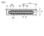
- the power receiving coil 250A has a so-called single winding structure, but is wound so that adjacent coil portions of the power receiving coil 250A partially overlap each other. Even in this configuration, the magnetic flux density is increased, the size of the power receiving device in the direction in which the winding central axis extends is reduced, or the thickness of the power receiving device is suppressed from increasing in the extending direction of the winding central axis. It is possible to reduce the size of the power receiving device. In the examples shown in FIGS. 6 and 7, a triple winding structure may be used as necessary, and a multistage structure of more than that may be adopted.
- FIG. 8 is a perspective view showing a power receiving coil 250B used in the power receiving device 200D (see FIG. 9) in the fourth modified example.
- FIG. 9 is a perspective view showing a power receiving device 200D in the fourth modified example.
- FIG. 9 does not illustrate the housing of the power receiving device 200D.
- the power receiving coil 250D has a so-called flat braiding wire structure.
- the power receiving coil 250D includes a base material 253 having a flat belt-like shape, and a plurality of strands 254 wound around the base material 253 in a braided shape.
- the strands 254 are thin conductive wires, and a plurality of strands 254 are converged, braided or twisted and wound around the base 253.
- the power receiving coil 250B has a long side portion 251 and a short side portion 252 and is spirally wound around the core 240 via the fixing member 260. (See FIG. 9).
- the thickness of a power receiving apparatus becomes thick also by the structure of the power receiving coil 250D. That is, when the case where the power receiving coil 250B is used is compared with the case where a round coil (coil wire) having the same coil cross-sectional area as the power receiving coil 250B is used, the thickness of the power receiving device is greater when the power receiving coil 250B is used. Since the dimension value in the vertical direction can be reduced, the power receiving device can be thinned.
- the proximity effect is a phenomenon in which AC resistance (high frequency resistance) increases or heat generation increases due to the influence of a magnetic field generated from conductors arranged in proximity. According to the power receiving coil 250B, even if the proximity effect occurs, the proximity effect is dispersed into the proximity effect to the inside (in other words, the proximity effect is dispersed into the effect on other currents in the same bundle. Therefore, the proximity effect to the outside (the effect on the current flowing through other bundles) can be reduced. As a result, the AC resistance (high-frequency resistance) decreases and the amount of heat generation decreases, so that a configuration with excellent heat dissipation can be realized.
- Patent Document 2 Japanese Utility Model Publication No. 04-099311
- Patent Document 3 Japanese Patent Application Laid-Open No. 08-022720
- a litz wire having a round cross section is used.
- AC resistance high-frequency resistance
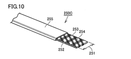
- FIG. 10 is a perspective view showing a power receiving coil 250C used in a power receiving device (not shown) in the fifth modification.
- the power receiving coil 250C further includes an insulating sheath 255 in addition to the configuration of the power receiving coil 250B (FIG. 8).
- the sheath 255 covers the base material 253 and the strands 254 wound around the base material 253, and protects them.
- the power receiving coil 250B (see FIGS. 8 and 9) of the fourth modified example is wound around the fixing member 260 (core 240).
- An end portion of the fixing member 260 (a portion corresponding to the folded portion of the power receiving coil 250B) may have an angular shape. Since the wire 254 of the power receiving coil 250 ⁇ / b> B is not covered and exposed, the wire 254 may be slid or caught on the end of the fixing member 260.
- the power receiving coil 250 ⁇ / b> C (FIG. 10) of the present modification since the strand 254 is covered and protected by the sheath 255, the strand 254 is slid or caught on the end portion of the fixing member 260. There is no. Since it is suppressed that the strand 254 is damaged or the strand 254 is broken, the life of the power receiving coil 250C can be extended.
- the power receiving coil 250C may be manufactured by tube extrusion (FIG. 11) or by solid extrusion (FIG. 12).
- a base 270 and a core 271 are prepared.
- the base material 253 on which the wire 254 is wound is disposed in the base 270 in a preheated state, and is positioned by the mandrel 271.
- the insulating resin polyethylene resin or the like
- the base material 253 around which the wire 254 is wound is covered with the sheath 255.
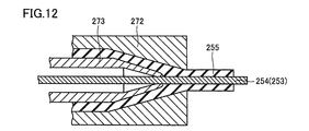
- a base 272 and a core 273 are prepared.
- the end of the core 273 (the end of the core 273 located on the right side in FIG. 12) is located inside the base 272.
- the base material 253 around which the wire 254 is wound is disposed in the base 272 in a preheated state, and is positioned by the mandrel 273. Thereafter, the resin poured between the inner surface of the base 272 and the outer surface of the core 273 is pushed out from the opening of the base 272 toward the right side of FIG. 12 and solidifies by cooling.
- the base material 253 around which the wire 254 is wound is covered with the sheath 255.
- the power receiving coil is formed in a flat plate shape so as to have a long side portion and a short side portion in a cross-sectional shape, and the long side portion of the power receiving coil faces the surface of the core.
- the power transmission coil is formed in a flat plate shape having a long side portion and a short side portion in a cross-sectional shape, and is wound so that the transmission side portion of the power transmission coil faces the surface of the core.
- the power transmission device can be reduced in thickness.
- 100 electric vehicle 110 vehicle body, 112 bottom surface, 114 floor panel, 130 rectifier, 200, 200A, 200B, 200C, 200D, 200G power receiving device, 210 power receiving unit, 220, 420 capacitor, 230, 430 coil unit, 240, 440 Core, 250, 250A, 250B, 250C, 250D, 250G Power receiving coil (coil), 251 long side, 252 short side, 253 substrate, 254 strand, 255 sheath, 260 fixing member, 270, 272 base, 271 , 273 core, 280 housing, 400 power transmission device, 410 power transmission unit, 450 power transmission coil, H1, H2 thickness, O2 winding center axis.
Landscapes
- Engineering & Computer Science (AREA)
- Power Engineering (AREA)
- Transportation (AREA)
- Mechanical Engineering (AREA)
- Computer Networks & Wireless Communication (AREA)
- Chemical & Material Sciences (AREA)
- Combustion & Propulsion (AREA)
- Current-Collector Devices For Electrically Propelled Vehicles (AREA)
- Electric Propulsion And Braking For Vehicles (AREA)
- Arrangement Or Mounting Of Propulsion Units For Vehicles (AREA)
- Charge And Discharge Circuits For Batteries Or The Like (AREA)
Abstract
受電装置(200)は、平板状のコア(240)と、コアに螺旋状に巻回され、巻回中心軸が水平方向に延びるコイル(250)とを備える。コイルは、コイルの延びる方向に対して垂直な平面でコイルを断面視した場合に長辺部(251)と短辺部(252)とを有するように平板状に形成される。コイルは、長辺部がコアの表面と対向するようにコアに巻回されている。したがって、受電装置の薄型化を図ることができる。
Description
本発明は、車両外部に設けられた送電装置から非接触で電力を受電する受電装置に関する。
非接触で電力を伝送する受電装置および送電装置が知られている。これらの装置は、コアと、コアに巻回されたコイルとをそれぞれ備えている。下記の特許文献1に開示されているように、コイル(コイル線)としては、断面形状が丸形状のものを採用するのが一般的である。下記の特許文献2,3では、断面形状が丸型のリッツ線が開示されている。このリッツ線は、複数のエナメル線などが撚り合わされることにより形成されている。
受電装置は、車両の底面に配置されることから、地面との干渉や車高制限等の観点から薄型化が求められる。いわゆるソレノイド型のコイルユニットを採用した受電装置においては、コア厚さと、コイル線径の2倍の厚さとが少なくとも必要である。従来では、コイル線として丸形状のものが用いられているため、コイル線径の分の厚さが厚くなっており、受電装置を薄型化する妨げとなっていた。
本発明は、上記のような実情に鑑みてなされたものであって、薄型化を図ることが可能な受電装置を提供することを目的とする。
受電装置は、平板状のコアと、上記コアに螺旋状に巻回され、巻回中心軸が水平方向に延びるコイルとを備える。上記コイルは、上記コイルの延びる方向に対して垂直な平面で上記コイルを断面視した場合に長辺部と短辺部とを有するように平板状に形成されている。上記コイルは、上記長辺部が上記コアの表面と対向するように上記コアに巻回されている。
上記の構成によれば、コイルの長辺部がコアの表面と対向するように配置されるため、たとえば同一断面積を有する丸形状のコイル(コイル線)を用いる場合に比べて薄型化を図ることができる。
実施の形態について、以下、図面を参照しながら説明する。個数および量などに言及する場合、特に記載がある場合を除き、本発明の範囲は必ずしもその個数およびその量などに限定されない。同一の部品および相当部品に対しては、同一の参照番号を付し、重複する説明は繰り返さない場合がある。
(電力伝送システム1000)
図1は、実施の形態における受電装置200が適用される電力伝送システム1000の全体構成を模式的に示す図である。電力伝送システム1000は、電動車両100および外部給電装置300を備える。電動車両100は、車両本体110および受電装置200を含む。車両本体110は、車両ECU120、整流器130、DC/DCコンバータ140、バッテリ150、パワーコントロールユニット160、モータユニット170、および通信部180などを有する。受電装置200は、整流器130に接続されている。受電装置200は、受電コイル250(コイル)を有し、車両本体110の底面に配置される。
図1は、実施の形態における受電装置200が適用される電力伝送システム1000の全体構成を模式的に示す図である。電力伝送システム1000は、電動車両100および外部給電装置300を備える。電動車両100は、車両本体110および受電装置200を含む。車両本体110は、車両ECU120、整流器130、DC/DCコンバータ140、バッテリ150、パワーコントロールユニット160、モータユニット170、および通信部180などを有する。受電装置200は、整流器130に接続されている。受電装置200は、受電コイル250(コイル)を有し、車両本体110の底面に配置される。
外部給電装置300は、送電装置400、高周波電力装置310、送電ECU320、および通信部322を含む。高周波電力装置310は、交流電源330に接続される。送電装置400は、駐車スペース内に設けられ、高周波電力装置310に接続される。送電装置400は、送電部410と、送電部410を収容する筐体(図示せず)とを含む。
送電部410は、ソレノイド型のコイルユニット430と、コイルユニット430に接続されたコンデンサ420とを有する。コイルユニット430は、フェライトを用いて作製された平板状のコア440と、コア440を挟持して固定する樹脂製の固定部材(図示せず)と、この固定部材を介してコア440に螺旋状に巻回され、巻回中心軸(図示せず)の周囲を取り囲むように形成された送電コイル450とにより構成される。
電力伝送システム1000においては、受電コイル250が送電コイル450に対向した状態で、受電装置200は送電装置400から電力を非接触で受電する。たとえば、車両本体110が停止しているときに給電ボタンがオン状態に設定されたことを車両ECU120が検出した場合、車両の動作モードは充電モードに切り替えられる。車両ECU120は、通信部180および通信部322を介して、外部給電装置300によるバッテリ150の充電制御の実行を指示する。
(受電装置200)
図2および図3を参照して、受電装置200についてより詳細に説明する。図2は、電動車両100を示す底面図であり、図3は、図2中のIII-III線に沿った矢視断面図である。図2および図3において、「D」は、鉛直方向下方Dを示す。「L」は、車両左方向Lを示す。「R」は、車両右方向Rを示す。「F」は、車両前進方向Fを示す。「B」は、車両後退方向Bを示す。「U」は、鉛直方向上方Uを示す。これらについては、後述する図4~図7においても共通している。
図2および図3を参照して、受電装置200についてより詳細に説明する。図2は、電動車両100を示す底面図であり、図3は、図2中のIII-III線に沿った矢視断面図である。図2および図3において、「D」は、鉛直方向下方Dを示す。「L」は、車両左方向Lを示す。「R」は、車両右方向Rを示す。「F」は、車両前進方向Fを示す。「B」は、車両後退方向Bを示す。「U」は、鉛直方向上方Uを示す。これらについては、後述する図4~図7においても共通している。
図2を参照して、車両本体110は、底面112を有している。底面112とは、電動車両100の車輪が地面に接地した状態において、地面に対して鉛直方向下方Dに離れた位置から車両本体110を見たときに、車両本体110のうちの視認可能な領域である。底面112には、フロアパネル114等が設けられる。受電装置200は、車両本体110の底面112に設けられる。受電装置200を底面112に固定するためには、受電装置200をフロアパネル114に固定してもよいし、受電装置200をサイドメンバまたはクロスメンバから懸架してもよい。
図2および図3を参照して、受電装置200は、受電部210と、受電部210を収容する筐体280とを含む。筐体280は、下方に向けて開口する形状を有する収容部281(図3)と、収容部281の開口を閉塞する底部287(図3)とを含んでいる。収容部281は、銅などの金属製の部材により構成され、底部287は、樹脂製の部材により構成される。
受電部210は、ソレノイド型のコイルユニット230と、コイルユニット230に接続されたコンデンサ220とを有する(図1も参照)。コイルユニット230は、フェライトを用いて作製された平板状のコア240と、コア240を挟持して固定する樹脂製の固定部材260(図3参照)と、固定部材260を介してコア240に螺旋状に巻回され、巻回中心軸O2(図2参照)の周囲を取り囲むように形成された受電コイル250とにより構成される。
受電コイル250の巻回中心軸O2は、水平方向に延びている。言い換えれば、電動車両100が水平な地面上に配置されている状態において、受電コイル250の巻回中心軸O2は水平方向に対して平行である。本実施の形態では、巻回中心軸O2は、車両本体110の前後方向に対しても平行である。送電コイル450(図1参照)の巻回中心軸も水平方向に延びており、電動車両100が駐車スペース内の電力伝送可能な所定位置に駐車した場合に、受電コイル250の巻回中心軸O2と送電コイル450(図1)の巻回中心軸とは互いに平行になることが企図されている。
上記の水平方向とは、完全な水平方向に限られず、略水平方向も含む。略水平方向とは、水平方向から0°より大きく±15°以下の範囲でずれた状態を含む。各巻回中心軸は、好ましくは、水平方向に対して-10°以上10°以下の角度範囲で延びているとよく、より好ましくは、水平方向に対して-5°以上5°以下の角度範囲で延びているとよく、最適には、水平方向に延びているとよい。
図3に示すように、受電コイル250は、いわゆるエッジワイズコイルの形状を有している。受電コイル250は、受電コイル250の延びる方向に対して垂直な平面で受電コイル250を断面視した場合に長辺部251と短辺部252とを有するように平板状に形成されている。受電コイル250は、断面形状が長方形であり、2つの長辺部251と2つの短辺部252とを有している。長辺部251の長さは、短辺部252の長さよりも長い。受電コイル250は、長辺部251がコア240の表面と(固定部材260を介して)対向するように、固定部材260を介してコア240に巻回されている。すなわち、受電コイル250は、長辺部251が平板状のコア240の表面に沿うように配置されている。
長辺部251と短辺部252とを有する平板状に形成された受電コイル250としては、断面形状が長方形であるものに限られず、断面形状が長円形であるものを採用してもよい。長円形とは、長方形の4つの角部が丸みを有するようにその長方形を変形させた形状である。断面形状において縦横の長さが異なり且つ長辺部251と短辺部252とを有するものであれば、平板状に形成された受電コイル250としては、長方形および長円形以外の形状を有していてもよい。ここで言う「辺」とは、直線状の部位に限られず、曲線状の部位も含まれるものである。すなわち、断面形状において長手方向を有し且つ長辺部251と短辺部252とを有するものであれば、平板状に形成された受電コイル250としては、たとえば楕円形状を有していてもよい。
以上のような断面形状を有する受電コイル250は、たとえば、複数本の細い銅線を束ねて銅線束を作製し、その銅線束を固定部材260の周囲に巻回することにより構成される。この構成に限られず、受電コイル250は、複数本の細い銅線を束ねて銅線束を作製し、その銅線束を絶縁体で覆うことによりコイル線を構成し、そのコイル線を固定部材260の周囲に巻回することにより構成してもよい。受電コイル250は、複数本の細いリッツ線束を束ねることによりコイル線を構成し、そのコイル線を固定部材260の周囲に巻回するようことにより構成してもよい。
上記の受電装置200においては、受電コイル250の長辺部251がコア240(固定部材260)の表面と対向するように配置される。磁束密度=磁束/(コイル断面積×巻数)であるため、たとえば同一の磁束密度を得るための条件を比較した場合、すなわち、受電コイル250と、受電コイル250と同じコイル断面積を有する丸形状のコイル(コイル線)とを用いる場合を比較した場合には、受電コイル250を用いる場合の方が受電装置の厚さ方向における寸法値を小さくできるため、受電装置の薄型化を図ることができる。
図4は、比較例として、丸形状を有する受電コイル250Gを備えた受電装置200Gを示す断面図である。受電コイル250Gは、長辺部および短辺部を有していないため、薄型化することは難しい。したがって、受電装置200Gの厚さH2に比べて、図3中に示す受電装置200の厚さH1の方が小さくすることができる。実施の形態における受電装置200は、比較例における受電装置200Gに比べてより小さな(厚さの薄い)空間内に配置されることができ、地面との干渉や車高制限等の観点において優れていると言える。
図5は、第1変形例における受電装置200Aを示す断面図である。受電装置200Aでは、受電コイル250Aが用いられる。受電コイル250Aは、上記の受電コイル250(図3)の場合と同様に長辺部251と短辺部252とを有しており、さらに表面にシース255(外皮絶縁体)が設けられている。隣り合う受電コイル250A(コイル部分)は、互いに接触するように密に配置されている。コイル線ギャップを小さくできるので、たとえば巻数を多くすることにより、磁束密度を増やすことができる。若しくは、磁束密度を増やさない場合には、受電コイルを密に配置することによって、受電装置の巻回中心軸の延びる方向における寸法を小さくすることが可能となる。すなわち、受電装置の厚さが厚くなることを抑制しつつ、巻回中心軸の延びる方向における受電装置の寸法を小さくすることも可能である。
図6は、第2変形例における受電装置200Bを示す断面図である。受電装置200Bでも、受電コイル250Aが用いられる。受電コイル250Aは、内側に巻回される部位と、外側に巻回される部位とが形成されるように、2重(多段)に巻回されている。受電コイル250Aの平板状であるという特徴を活用することによって、このようなレイアウトも実現でき、磁束密度を増加させたり、巻回中心軸の延びる方向における受電装置の寸法を小さくしたり、受電装置の厚さが厚くなることを抑制しつつ巻回中心軸の延びる方向における受電装置の寸法を小さくしたりすることが可能となる。
図7は、第3変形例における受電装置200Cを示す断面図である。受電装置200Cでも、受電コイル250Aが用いられる。受電コイル250Aは、いわゆる1重巻き構造を有しているが、隣り合う受電コイル250Aのコイル部分同士が部分的に重なるように巻回されている。当該構成によっても、磁束密度を増加させたり、巻回中心軸の延びる方向における受電装置の寸法を小さくしたり、受電装置の厚さが厚くなることを抑制しつつ巻回中心軸の延びる方向における受電装置の寸法を小さくしたりすることが可能となる。図6および図7に示す例においては、必要に応じて、3重巻きの構造にすることも可能であり、それ以上の多段構造を採用してもよい。
図8は、第4変形例における受電装置200D(図9参照)に用いられる受電コイル250Bを示す斜視図である。図9は、第4変形例における受電装置200Dを示す斜視図である。便宜上のため、図9には受電装置200Dの筐体などを図示していない。図8および図9に示すように、受電コイル250Dは、いわゆる平打編組線(flat braiding wire)の構造を有している。
具体的には、受電コイル250Dは、扁平な帯状の形状を有する基材253と、基材253の周囲に編組状に巻かれた複数本の素線254とを含んでいる。素線254は、導電性を有する細線であり、複数本の素線254が集束して編組または撚り合わせて基材253の周囲に巻回されている。受電コイル250Bも、上記の受電コイル250(図3)の場合と同様に長辺部251と短辺部252とを有しており、固定部材260を介してコア240の周囲に螺旋状に巻回されている(図9参照)。
受電コイル250Dの構成によっても、受電装置の厚さが厚くなることを抑制できる。すなわち、受電コイル250Bを用いる場合と、受電コイル250Bと同じコイル断面積を有する丸形状のコイル(コイル線)を用いる場合とを比較したとき、受電コイル250Bを用いる場合の方が受電装置の厚さ方向における寸法値を小さくできるため、受電装置の薄型化を図ることができる。
受電コイル250Bを用いる場合には、近接効果の影響を受けにくくなるという利点も得られる。近接効果とは、近接配置された導体から発生した磁場の影響により、交流抵抗(高周波抵抗)が増加したり、発熱量が増加したりする現象である。受電コイル250Bによれば、近接効果が発生したとしてもその近接効果は内部への近接効果へと分散されるため(換言すると、近接効果は同一束内の他の電流への効果へと分散されるため)、外部への近接効果(他の束に流れる電流への効果)を減少させることができる。結果として、交流抵抗(高周波抵抗)が小さくなり発熱量が低下するため、放熱性に優れた構成を実現できる。
なお、冒頭で述べた特許文献2(実開平04-099311号公報)や特許文献3(特開平08-022720号公報)の構成では、断面形状が丸型のリッツ線が用いられている。断面形状が丸型のリッツ線を用いる場合には、受電装置が厚くなるだけでなく、近接効果の影響により交流抵抗(高周波抵抗)が大きくなるということも考えられる。
図10は、第5変形例における受電装置(図示せず)に用いられる受電コイル250Cを示す斜視図である。受電コイル250Cは、上記の受電コイル250B(図8)の構成に加えて、絶縁性を有するシース255をさらに有している。シース255は、基材253と基材253に巻回された素線254とを被覆しており、これらを保護している。
上記の第4変形例の受電コイル250B(図8,図9参照)を固定部材260(コア240)の周囲に巻回したとする。固定部材260の端部(受電コイル250Bの折り返し部分に対応する箇所)は、角張った形状を有している場合がある。受電コイル250Bの素線254は、被覆されておらず露出しているため、素線254が固定部材260の端部に摺れたり引っ掛かったりすることがある。
これに対して本変形例の受電コイル250C(図10)は、素線254がシース255により被覆および保護されているため、素線254が固定部材260の端部に摺れたり引っ掛かったりすることはない。素線254が傷付いたり、素線254の断線が発生したりすることは抑制されるため、受電コイル250Cの長寿命化が図れる。受電コイル250Cは、チューブ押出(図11)により作製してもよいし、充実押出(図12)により作製してもよい。
図11を参照して、受電コイル250Cをチューブ押出により作製する場合には、口金270および心金271が準備される。素線254が巻回された基材253は、余熱された状態で口金270の中に配置され、心金271によって位置決めされる。その後、口金270の内表面と心金271の外表面との間に流し込まれた絶縁性の樹脂(ポリエチレン樹脂など)は、口金270の開口部から図11の紙面右側に向かってチューブ状に押し出され、冷却により固化する。素線254が巻回された基材253は、シース255により被覆されることとなる。
図12を参照して、受電コイル250Cを充実押出により作製する場合には、口金272および心金273が準備される。心金273の端部(心金273のうちの図12の紙面右側に位置する端部)は、口金272の内部に位置している。素線254が巻回された基材253は、余熱された状態で口金272の中に配置され、心金273によって位置決めされる。その後、口金272の内表面と心金273の外表面との間に流し込まれた樹脂は、口金272の開口部から図12の紙面右側に向かって押し出され、冷却により固化する。素線254が巻回された基材253は、シース255により被覆されることとなる。
ここで、充実押出(図12)の場合、素線254(図10)の周りを樹脂が被覆する際に、素線254には樹脂から押し付けられるような圧力が作用し、隣接する素線254の間の隙間が樹脂により埋められる。充実押出でシース255を形成する場合には、素線254(リッツ線)に圧力が加わる。したがって、素線254が断線することをより確実に防ぐという観点からは、チューブ押出により受電コイル250Cを作製することが好適である。
チューブ押出(図11)の場合、素線254が巻回された基材253の周りを樹脂がチューブ状に押し出され、シース255の被覆厚さは略一定となる。このため、充実押出の場合に比べて、素線254とシース255との間の密着力を低下させることもできる。受電コイル250Cを固定部材260(コア240)へ巻き付ける際、素線254とシース255との間の密着力が低いため、固定部材260の端部付近で受電コイル250Cの素線254に局所的な応力が作用することも抑制され、素線254が断線することをより確実に防ぐことが可能となる。
以上の実施の形態および各変形例は、受電コイルが断面形状において長辺部および短辺部を有するように平板状に形成され、且つ受電コイルの長辺部がコアの表面と対向するように巻回されているという構成に基づき説明したが、このような構成は送電装置の送電コイルにも同様に適用できるものである。すなわち、送電コイルが断面形状において長辺部および短辺部を有するように平板状に形成され、且つ送電コイルの送辺部がコアの表面と対向するように巻回されているという構成によれば、送電装置の薄型化を図ることができる。
以上、本発明に基づいた実施の形態および変形例について説明したが、今回開示された実施の形態よび変形例はすべての点で例示であって制限的なものではない。本発明の技術的範囲は請求の範囲によって示され、請求の範囲と均等の意味および範囲内でのすべての変更が含まれることが意図される。
100 電動車両、110 車両本体、112 底面、114 フロアパネル、130 整流器、200,200A,200B,200C,200D,200G 受電装置、210 受電部、220,420 コンデンサ、230,430 コイルユニット、240,440 コア、250,250A,250B,250C,250D,250G 受電コイル(コイル)、251 長辺部、252 短辺部、253 基材、254 素線、255 シース、260 固定部材、270,272 口金、271,273 心金、280 筐体、400 送電装置、410 送電部、450 送電コイル、H1,H2 厚さ、O2 巻回中心軸。
Claims (4)
- 平板状のコアと、
前記コアに螺旋状に巻回され、巻回中心軸が水平方向に延びるコイルとを備え、
前記コイルは、前記コイルの延びる方向に対して垂直な平面で前記コイルを断面視した場合に長辺部と短辺部とを有するように平板状に形成され、
前記コイルは、前記長辺部が前記コアの表面と対向するように前記コアに巻回されている、受電装置。 - 前記コイルの表面には、外皮絶縁体が設けられており、隣り合う前記コイルは互いに接触するように配置されている、
請求項1に記載の受電装置。 - 前記コイルは、前記コアに多重巻きされている、
請求項1または2に記載の受電装置。 - 前記コイルは、平打編組線の構造を有している、
請求項1から3のいずれか1項に記載の受電装置。
Priority Applications (3)
| Application Number | Priority Date | Filing Date | Title |
|---|---|---|---|
| EP14861824.2A EP3076413A4 (en) | 2013-11-18 | 2014-11-11 | ENERGY RECEIVING DEVICE |
| CN201480061710.3A CN105745726A (zh) | 2013-11-18 | 2014-11-11 | 受电装置 |
| US15/035,778 US10124685B2 (en) | 2013-11-18 | 2014-11-11 | Power reception device having a coil formed like a flat plate |
Applications Claiming Priority (2)
| Application Number | Priority Date | Filing Date | Title |
|---|---|---|---|
| JP2013237848A JP6262500B2 (ja) | 2013-11-18 | 2013-11-18 | 受電装置 |
| JP2013-237848 | 2013-11-18 |
Publications (1)
| Publication Number | Publication Date |
|---|---|
| WO2015072436A1 true WO2015072436A1 (ja) | 2015-05-21 |
Family
ID=53057370
Family Applications (1)
| Application Number | Title | Priority Date | Filing Date |
|---|---|---|---|
| PCT/JP2014/079794 Ceased WO2015072436A1 (ja) | 2013-11-18 | 2014-11-11 | 受電装置 |
Country Status (5)
| Country | Link |
|---|---|
| US (1) | US10124685B2 (ja) |
| EP (1) | EP3076413A4 (ja) |
| JP (1) | JP6262500B2 (ja) |
| CN (1) | CN105745726A (ja) |
| WO (1) | WO2015072436A1 (ja) |
Cited By (1)
| Publication number | Priority date | Publication date | Assignee | Title |
|---|---|---|---|---|
| JP2023529333A (ja) * | 2020-06-01 | 2023-07-10 | エロンロード、アクチボラグ | 集電器のための接触部材 |
Citations (6)
| Publication number | Priority date | Publication date | Assignee | Title |
|---|---|---|---|---|
| JPH0499311U (ja) | 1990-10-12 | 1992-08-27 | ||
| JPH0822720A (ja) | 1994-07-07 | 1996-01-23 | Riken Densen Kk | リッツ線 |
| JPH10106866A (ja) * | 1996-06-27 | 1998-04-24 | Sumitomo Wiring Syst Ltd | 電気自動車充電用磁気結合装置 |
| JP2002208527A (ja) * | 2001-01-12 | 2002-07-26 | Toko Inc | 漏れ磁束型電力変換トランス |
| JP2013106477A (ja) * | 2011-11-15 | 2013-05-30 | Toshiba Corp | 共振子および無線電力伝送装置 |
| JP2013154815A (ja) | 2012-01-31 | 2013-08-15 | Toyota Motor Corp | 車両および電力伝送システム |
Family Cites Families (21)
| Publication number | Priority date | Publication date | Assignee | Title |
|---|---|---|---|---|
| US5907231A (en) | 1996-06-27 | 1999-05-25 | Sumitomo Electriic Industries, Ltd. | Magnetic coupling device for charging an electric vehicle |
| JP2002027693A (ja) * | 2000-07-10 | 2002-01-25 | Mitsubishi Electric Corp | 回転電機用巻線導体 |
| CN102983639B (zh) | 2005-07-12 | 2016-01-27 | 麻省理工学院 | 无线非辐射能量传递 |
| US7825543B2 (en) | 2005-07-12 | 2010-11-02 | Massachusetts Institute Of Technology | Wireless energy transfer |
| JP2007287830A (ja) * | 2006-04-14 | 2007-11-01 | Sumida Corporation | 磁気素子 |
| EP2130287A1 (en) | 2007-03-27 | 2009-12-09 | Massachusetts Institute of Technology | Wireless energy transfer |
| JP4743244B2 (ja) * | 2008-09-18 | 2011-08-10 | トヨタ自動車株式会社 | 非接触受電装置 |
| JP5051915B2 (ja) * | 2008-10-28 | 2012-10-17 | 東海ゴム工業株式会社 | 流体封入式防振装置 |
| JP5467569B2 (ja) | 2009-01-21 | 2014-04-09 | 国立大学法人埼玉大学 | 非接触給電装置 |
| KR101040662B1 (ko) * | 2009-04-06 | 2011-06-13 | 한국과학기술원 | 전기자동차용 초박형 급전장치와 집전장치 |
| JP2011018708A (ja) * | 2009-07-07 | 2011-01-27 | Sumitomo Electric Ind Ltd | 超電導コイル |
| JP2011124129A (ja) | 2009-12-11 | 2011-06-23 | Showa Aircraft Ind Co Ltd | 高周波用の電線 |
| JP6094762B2 (ja) * | 2010-09-14 | 2017-03-15 | ウィトリシティ コーポレーション | 無線エネルギー分配システム |
| JP5970158B2 (ja) * | 2011-02-10 | 2016-08-17 | 国立大学法人埼玉大学 | 非接触給電装置 |
| JP2012175741A (ja) * | 2011-02-18 | 2012-09-10 | Daihatsu Motor Co Ltd | 集中巻コイル |
| JP5853199B2 (ja) * | 2011-08-25 | 2016-02-09 | パナソニックIpマネジメント株式会社 | 非接触給電システムの金属異物検出方法、非接触給電装置、電気機器に設けられた受電装置及び非接触給電システム |
| JP5825108B2 (ja) | 2012-01-16 | 2015-12-02 | トヨタ自動車株式会社 | 受電装置および送電装置 |
| CN104335450A (zh) * | 2012-05-09 | 2015-02-04 | 丰田自动车株式会社 | 能够以非接触的方式接受电力的车辆 |
| JP2015019551A (ja) * | 2013-07-12 | 2015-01-29 | 本田技研工業株式会社 | 非接触給電システム |
| JP6225551B2 (ja) * | 2013-08-08 | 2017-11-08 | 株式会社Ihi | 共振器 |
| JP6423142B2 (ja) * | 2013-10-01 | 2018-11-14 | トヨタ自動車株式会社 | 受電装置、送電装置および車両 |
-
2013
- 2013-11-18 JP JP2013237848A patent/JP6262500B2/ja active Active
-
2014
- 2014-11-11 WO PCT/JP2014/079794 patent/WO2015072436A1/ja not_active Ceased
- 2014-11-11 EP EP14861824.2A patent/EP3076413A4/en not_active Withdrawn
- 2014-11-11 US US15/035,778 patent/US10124685B2/en active Active
- 2014-11-11 CN CN201480061710.3A patent/CN105745726A/zh active Pending
Patent Citations (6)
| Publication number | Priority date | Publication date | Assignee | Title |
|---|---|---|---|---|
| JPH0499311U (ja) | 1990-10-12 | 1992-08-27 | ||
| JPH0822720A (ja) | 1994-07-07 | 1996-01-23 | Riken Densen Kk | リッツ線 |
| JPH10106866A (ja) * | 1996-06-27 | 1998-04-24 | Sumitomo Wiring Syst Ltd | 電気自動車充電用磁気結合装置 |
| JP2002208527A (ja) * | 2001-01-12 | 2002-07-26 | Toko Inc | 漏れ磁束型電力変換トランス |
| JP2013106477A (ja) * | 2011-11-15 | 2013-05-30 | Toshiba Corp | 共振子および無線電力伝送装置 |
| JP2013154815A (ja) | 2012-01-31 | 2013-08-15 | Toyota Motor Corp | 車両および電力伝送システム |
Non-Patent Citations (1)
| Title |
|---|
| See also references of EP3076413A4 * |
Cited By (2)
| Publication number | Priority date | Publication date | Assignee | Title |
|---|---|---|---|---|
| JP2023529333A (ja) * | 2020-06-01 | 2023-07-10 | エロンロード、アクチボラグ | 集電器のための接触部材 |
| JP7625620B2 (ja) | 2020-06-01 | 2025-02-03 | エロンロード、アクチボラグ | 集電器のための接触部材 |
Also Published As
| Publication number | Publication date |
|---|---|
| EP3076413A4 (en) | 2016-11-16 |
| CN105745726A (zh) | 2016-07-06 |
| US10124685B2 (en) | 2018-11-13 |
| JP2015099817A (ja) | 2015-05-28 |
| EP3076413A1 (en) | 2016-10-05 |
| JP6262500B2 (ja) | 2018-01-17 |
| US20160288654A1 (en) | 2016-10-06 |
Similar Documents
| Publication | Publication Date | Title |
|---|---|---|
| JP5229381B2 (ja) | モータ用導線およびモータ用コイル | |
| CN104137362A (zh) | 电线的布线结构和带有外装部件的电线 | |
| CN110853897B (zh) | 线圈装置以及线圈装置的制造方法 | |
| CN108140478A (zh) | 线圈装置 | |
| JP5246411B2 (ja) | リアクトル、コンバータ、およびリアクトルの製造方法 | |
| WO2010086944A1 (ja) | 絶縁電線およびコイル | |
| JP2016110836A (ja) | キャブタイヤケーブル、及び、コネクタ付ケーブル | |
| JP5393097B2 (ja) | アルファ巻きコイル | |
| JP5978509B2 (ja) | 高圧導電路及びワイヤハーネス | |
| JP2012256480A (ja) | 電気自動車充電用平型ケーブル | |
| JP2013026015A (ja) | ワイヤハーネス | |
| JP2021034296A (ja) | 導線およびコイル部材 | |
| JP6971062B2 (ja) | 非接触給電装置用コイルおよび非接触給電装置用コイルの製造方法 | |
| JP2011229202A (ja) | 無線電力伝送用コイル | |
| JP5218772B2 (ja) | リアクトル、リアクトル用コイル、及びコンバータ | |
| JP6262500B2 (ja) | 受電装置 | |
| JP2013074144A5 (ja) | ||
| WO2016185724A1 (ja) | リッツ線、リッツ線コイル、及びリッツ線の製造方法 | |
| CN210325464U (zh) | 磁感线圈 | |
| JP3623858B2 (ja) | 高周波トランスの巻線 | |
| JP2012198996A (ja) | 平型ケーブル、及び、ワイヤハーネス | |
| JP5159269B2 (ja) | 複合電線およびコイル | |
| JP2009218399A (ja) | 集合コイル体及び集合コイル体の製造方法、モータ、リアクトル | |
| JP6894784B2 (ja) | サージ電圧低減部材 | |
| JP6308036B2 (ja) | リアクトル |
Legal Events
| Date | Code | Title | Description |
|---|---|---|---|
| 121 | Ep: the epo has been informed by wipo that ep was designated in this application |
Ref document number: 14861824 Country of ref document: EP Kind code of ref document: A1 |
|
| WWE | Wipo information: entry into national phase |
Ref document number: 15035778 Country of ref document: US |
|
| NENP | Non-entry into the national phase |
Ref country code: DE |
|
| REEP | Request for entry into the european phase |
Ref document number: 2014861824 Country of ref document: EP |
|
| WWE | Wipo information: entry into national phase |
Ref document number: 2014861824 Country of ref document: EP |