WO2015072557A1 - エンコーダおよびサーボシステム - Google Patents
エンコーダおよびサーボシステム Download PDFInfo
- Publication number
- WO2015072557A1 WO2015072557A1 PCT/JP2014/080277 JP2014080277W WO2015072557A1 WO 2015072557 A1 WO2015072557 A1 WO 2015072557A1 JP 2014080277 W JP2014080277 W JP 2014080277W WO 2015072557 A1 WO2015072557 A1 WO 2015072557A1
- Authority
- WO
- WIPO (PCT)
- Prior art keywords
- servo
- detection signal
- servo driver
- encoder
- information
- Prior art date
- Legal status (The legal status is an assumption and is not a legal conclusion. Google has not performed a legal analysis and makes no representation as to the accuracy of the status listed.)
- Ceased
Links
Images




Classifications
-
- G—PHYSICS
- G05—CONTROLLING; REGULATING
- G05B—CONTROL OR REGULATING SYSTEMS IN GENERAL; FUNCTIONAL ELEMENTS OF SUCH SYSTEMS; MONITORING OR TESTING ARRANGEMENTS FOR SUCH SYSTEMS OR ELEMENTS
- G05B19/00—Program-control systems
- G05B19/02—Program-control systems electric
- G05B19/18—Numerical control [NC], i.e. automatically operating machines, in particular machine tools, e.g. in a manufacturing environment, so as to execute positioning, movement or co-ordinated operations by means of program data in numerical form
- G05B19/414—Structure of the control system, e.g. common controller or multiprocessor systems, interface to servo, programmable interface controller
- G05B19/4144—Structure of the control system, e.g. common controller or multiprocessor systems, interface to servo, programmable interface controller characterised by using multiplexing for control system
-
- G—PHYSICS
- G05—CONTROLLING; REGULATING
- G05B—CONTROL OR REGULATING SYSTEMS IN GENERAL; FUNCTIONAL ELEMENTS OF SUCH SYSTEMS; MONITORING OR TESTING ARRANGEMENTS FOR SUCH SYSTEMS OR ELEMENTS
- G05B19/00—Program-control systems
- G05B19/02—Program-control systems electric
- G05B19/18—Numerical control [NC], i.e. automatically operating machines, in particular machine tools, e.g. in a manufacturing environment, so as to execute positioning, movement or co-ordinated operations by means of program data in numerical form
- G05B19/19—Numerical control [NC], i.e. automatically operating machines, in particular machine tools, e.g. in a manufacturing environment, so as to execute positioning, movement or co-ordinated operations by means of program data in numerical form characterised by positioning or contouring control systems, e.g. to control position from one programmed point to another or to control movement along a programmed continuous path
- G05B19/27—Numerical control [NC], i.e. automatically operating machines, in particular machine tools, e.g. in a manufacturing environment, so as to execute positioning, movement or co-ordinated operations by means of program data in numerical form characterised by positioning or contouring control systems, e.g. to control position from one programmed point to another or to control movement along a programmed continuous path using an absolute digital measuring device
- G05B19/31—Numerical control [NC], i.e. automatically operating machines, in particular machine tools, e.g. in a manufacturing environment, so as to execute positioning, movement or co-ordinated operations by means of program data in numerical form characterised by positioning or contouring control systems, e.g. to control position from one programmed point to another or to control movement along a programmed continuous path using an absolute digital measuring device for continuous-path control
- G05B19/311—Numerical control [NC], i.e. automatically operating machines, in particular machine tools, e.g. in a manufacturing environment, so as to execute positioning, movement or co-ordinated operations by means of program data in numerical form characterised by positioning or contouring control systems, e.g. to control position from one programmed point to another or to control movement along a programmed continuous path using an absolute digital measuring device for continuous-path control the positional error is used to control continuously the servomotor according to its magnitude
-
- H—ELECTRICITY
- H02—GENERATION; CONVERSION OR DISTRIBUTION OF ELECTRIC POWER
- H02K—DYNAMO-ELECTRIC MACHINES
- H02K11/00—Structural association of dynamo-electric machines with electric components or with devices for shielding, monitoring or protection
- H02K11/20—Structural association of dynamo-electric machines with electric components or with devices for shielding, monitoring or protection for measuring, monitoring, testing, protecting or switching
- H02K11/21—Devices for sensing speed or position, or actuated thereby
-
- H—ELECTRICITY
- H02—GENERATION; CONVERSION OR DISTRIBUTION OF ELECTRIC POWER
- H02K—DYNAMO-ELECTRIC MACHINES
- H02K11/00—Structural association of dynamo-electric machines with electric components or with devices for shielding, monitoring or protection
- H02K11/30—Structural association with control circuits or drive circuits
- H02K11/33—Drive circuits, e.g. power electronics
-
- G—PHYSICS
- G05—CONTROLLING; REGULATING
- G05B—CONTROL OR REGULATING SYSTEMS IN GENERAL; FUNCTIONAL ELEMENTS OF SUCH SYSTEMS; MONITORING OR TESTING ARRANGEMENTS FOR SUCH SYSTEMS OR ELEMENTS
- G05B2219/00—Program-control systems
- G05B2219/30—Nc systems
- G05B2219/33—Director till display
- G05B2219/33218—Motor encoders, resolvers on common bus with drives, servo controllers
-
- G—PHYSICS
- G05—CONTROLLING; REGULATING
- G05B—CONTROL OR REGULATING SYSTEMS IN GENERAL; FUNCTIONAL ELEMENTS OF SUCH SYSTEMS; MONITORING OR TESTING ARRANGEMENTS FOR SUCH SYSTEMS OR ELEMENTS
- G05B2219/00—Program-control systems
- G05B2219/30—Nc systems
- G05B2219/37—Measurements
- G05B2219/37149—Multiplexer to send encoder and rotor pole position to same output lines
-
- G—PHYSICS
- G05—CONTROLLING; REGULATING
- G05B—CONTROL OR REGULATING SYSTEMS IN GENERAL; FUNCTIONAL ELEMENTS OF SUCH SYSTEMS; MONITORING OR TESTING ARRANGEMENTS FOR SUCH SYSTEMS OR ELEMENTS
- G05B2219/00—Program-control systems
- G05B2219/30—Nc systems
- G05B2219/37—Measurements
- G05B2219/37151—Handling encoder signal, compensation for light variation, stray light
Definitions
- the present invention relates to an encoder and a servo system.
- the servo system generally has a motor, a servo amplifier, and a controller.
- a servo system disclosed in Japanese Patent Application Laid-Open No. 2010-67036 includes an upper master (controller) and a plurality of servo amplifiers.
- the external sensor for example, temperature sensor
- the external sensor is connected to one of the plurality of servo amplifiers by a cable.
- Servo driver may be separated from the servo motor due to layout or other reasons where the servo system is applied. In such a case, a relatively long cable is necessary for the cable connecting the servo driver and the servo motor.
- a sensor for detecting the movement of an object driven by a motor (for example, an object to be processed) must be arranged near the object. That is, the sensor is installed in the vicinity of the motor.
- the cable connecting the sensor and the servo driver also becomes long.
- An object of the present invention is to provide a configuration capable of improving the workability of sensor wiring in a servo system.
- An encoder detects an operation of a motor driven by a servo driver, generates a feedback signal indicating the detected operation, and detects an object driven by the motor.
- An input unit that receives a detection signal output from the sensor via a sensor cable, a feedback unit generated by the signal generation unit, and a communication unit for outputting the detection signal input to the input unit to the outside .
- the communication unit has an output terminal for transmitting the feedback signal and the detection signal through a common communication cable.
- the encoder is configured to be connectable to an electric device through a cable, and further includes a power supply terminal for supplying electric power to the electric device through the cable.
- the encoder is configured to be connectable to an electric device through a cable, and further includes a control terminal for outputting a control signal for controlling the electric device to the electric device through the cable.
- the encoder has an operation mode corresponding to use in a state where a plurality of servo drivers can communicate with each other.
- the communication unit transmits information indicating the servo driver corresponding to the destination of the detection signal in the operation mode.
- a servo system includes an encoder according to any one of the above, a motor, a servo driver for driving the motor, a sensor for detecting an object driven by the motor, and the sensor. And a sensor cable for transmitting the detection signal to the encoder.
- a servo system includes first and second motors, first and second servo drivers that drive the first and second motors, respectively, and first and second motors.
- a first and a second sensor for detecting an object driven by the assigned motor and outputting a detection signal; and a feedback signal indicating the operation of the first motor.
- a first encoder that receives a detection signal from the first sensor or the second sensor via a sensor cable and a feedback signal indicating the operation of the second motor are sent to the second servo driver.
- a second encoder for receiving a detection signal from the first sensor or the second sensor via the sensor cable.
- each of the first and second encoders When each of the first and second encoders receives a detection signal from a sensor assigned to a servo driver that drives a motor whose operation is detected by the encoder, the first and second encoders transmit the detection signal and together with the detection signal Alternatively, information indicating the servo driver corresponding to the destination of the detection signal is transmitted independently.
- the first and second encoders When each of the first and second encoders receives a detection signal from a sensor assigned to another servo driver, the first and second encoders transmit the detection signal and respond to the destination of the detection signal together with the detection signal or independently. Information indicating the other servo driver to be transmitted is transmitted.
- Each of the first and second servo drivers processes the detection signal based on information from an encoder connected to each servo driver, or passes the detection signal to a servo driver different from the servo driver. Decide whether to transfer.
- the information indicating the servo driver corresponding to the destination of the detection signal whether each of the first and second servo drivers processes the detection signal or transfers the detection signal to another servo driver. Determine based on.
- each of the first and second servo drivers receives information indicating the corresponding servo driver and a detection signal, and processes the detection signal with the servo driver, or outputs the detection signal to another Decide whether to transfer to the servo driver.
- each of the first and second encoders receives a detection signal from a sensor assigned to a servo driver that drives a motor whose operation is detected by the encoder
- the servo driver corresponds to the destination.
- each of the first and second servo drivers causes the other servo driver to correspond to the destination when receiving a detection signal from a sensor assigned to a servo driver different from the servo driver.
- Information is generated and a detection signal and information are transmitted.
- the servo system has an information recording unit in which the above information is recorded in advance. Whether each of the first and second servo drivers processes the detection signal by the servo driver based on the information recorded in the information recording unit, or transfers the detection signal to another servo driver To decide.
- each of the first and second servo drivers has an information recording unit.
- the information recorded in the information recording unit is information that is common between the first and second servo drivers and specifies the destination for each detection signal.
- each of the first and second servo drivers has an information recording unit in which information indicating that the destination of the detection signal is the servo driver is recorded, and the detection signal does not correspond to the destination indicated by the information Is received, the detection signal is transferred to another servo driver.
- the servo system further includes a monitoring device that monitors the first and second servo drivers.
- the monitoring device sets the servo driver so that the servo driver processes the detection signal.
- the servo driver sends the detection signal to the other servo driver. The servo driver is controlled to be transferred to the servo driver.
- the servo system further includes a monitoring device that monitors the first and second servo drivers.
- the monitoring apparatus determines a servo driver that should process the detection signal, and generates the information that associates the determined servo driver with the destination.
- the monitoring device transmits information indicating the corresponding servo driver to the servo driver that has received the detection signal.
- information indicating a servo driver corresponding to the destination of the detection signal is given to the detection signal.
- the detection signal and information indicating the servo driver corresponding to the destination of the detection signal are continuously transmitted.
- the detection signal and information indicating the servo driver corresponding to the destination of the detection signal are transmitted at time intervals.
- At least one of the first and second encoders is configured to be connectable to an electrical device through a cable, and supplies power to the electrical device through the cable.
- At least one of the first and second encoders is configured to be connectable to an electric device through a cable, and outputs a control signal for controlling the electric device to the electric device through the cable.
- the present invention it is possible to improve workability of sensor wiring in a servo system. Also, the complexity of wiring work can be reduced. Furthermore, the cost required for the cable and the cost required for the wiring work can be reduced.
- FIG. 1 is a block diagram schematically showing a configuration of a servo system according to a first embodiment of the present invention.
- FIG. 3 is a block diagram schematically showing a configuration of an encoder 31 shown in FIG. 2. It is the figure which showed the structural example of the encoder cable 41 shown in FIG. It is a block diagram which shows roughly the structure of the servo system which concerns on Embodiment 2 of this invention.
- FIG. 6 is a block diagram schematically showing a configuration of an encoder 32 shown in FIG. 5. It is a block diagram which shows roughly the structure of the servo system which concerns on Embodiment 3 of this invention.
- FIG. 3 is a block diagram schematically showing a configuration of an encoder 31 shown in FIG. 2. It is the figure which showed the structural example of the encoder cable 41 shown in FIG. It is a block diagram which shows roughly the structure of the servo system which concerns on Embodiment 2 of this invention.
- FIG. 6 is a block diagram schematically showing a configuration of an encode
- FIG. 8 is a block diagram schematically showing a configuration of an encoder 33 shown in FIG. 7. It is a block diagram which shows roughly the structure of the servo system which concerns on Embodiment 4 of this invention. It is a figure for demonstrating the correlation between a detection signal and the information which shows the servo driver corresponding to the destination of a detection signal. It is a block diagram which shows roughly the structure of the encoders 31 and 31a shown in FIG. It is a figure which shows the component relevant to distribution of a detection signal among the servo systems shown in FIG. It is a figure which shows the component related to distribution of a detection signal among the servo systems which concern on Embodiment 5. FIG.
- FIG. 1 It is a figure which shows the component relevant to distribution of a detection signal among the servo systems which concern on the modification 1 of Embodiment 5.
- FIG. 2 shows the component relevant to distribution of a detection signal among the servo systems which concern on the modification 2 of Embodiment 5.
- FIG. It is a figure which shows the component relevant to distribution of a detection signal among the servo systems which concern on Embodiment 6.
- FIG. It is a figure which shows the component relevant to distribution of a detection signal among the servo systems which concern on the modification of Embodiment 6.
- FIG. 6 shows the component relevant to distribution of a detection signal among the servo systems which concern on the modification of Embodiment 6.
- an industrial system is shown as an exemplary form of a servo system.
- the application of the servo system according to the present invention is not particularly limited.
- FIG. 1 is a block diagram schematically showing a configuration example of a general servo system.
- a servo system 900 includes a PLC (Programmable Logic Controller) 1, a servo driver 2, a servo motor 3, a coupling 51, a screw shaft 52, a precision stage 53, and a linear scale 54.
- An origin sensor 61, limit sensors 62 and 63, and a fully closed sensor 64 are provided.
- the PLC 1 outputs a command signal CM to the servo driver 2.
- the PLC 1 functions as a monitoring device for the servo driver 2, for example, by executing processing according to a program prepared in advance.
- Servo driver 2 receives command signal CM from PLC 1. Further, the servo driver 2 receives a feedback signal FB from the servo motor 3 and receives detection signals (DET1 to DET4) output from the origin sensor 61, the limit sensors 62 and 63, or the fully closed sensor 64. The servo driver 2 drives the servo motor 3 according to these signals. More specifically, the servo driver 2 controls the drive current I of the servo motor 3.
- Servo motor 3 includes a motor 30 and an encoder 39.
- the motor 30 is, for example, an AC servo motor.
- the motor 30 receives the drive current I from the servo driver 2 via the power cable 40.
- the encoder 39 detects the operation of the motor 30.
- the encoder 39 outputs a feedback signal FB indicating the detected operation to the servo driver 2 via the encoder cable 41.
- the coupling 51 couples the rotating shaft 301 of the motor 30 and the screw shaft 52.
- the precision stage 53 moves in the axial direction of the screw shaft 52 (indicated by a double arrow in FIG. 1) in accordance with the rotation of the rotation shaft 301 of the motor 30. That is, the precision stage 53 is an object driven by the motor 30.
- the moving amount and moving direction of the precision stage 53 are controlled based on the rotation speed and rotating direction of the motor 30. As shown in FIG. 1, for example, a workpiece 8 is placed on a precision stage 53.
- the origin sensor 61 and the limit sensors 62 and 63 are installed along the screw shaft 52 in order to detect the position of the precision stage 53. Origin sensor 61 and limit sensors 62 and 63 output detection signals DET1 to DET3 indicating that precision stage 53 has been detected.
- the origin sensor 61 and the limit sensors 62 and 63 are sensors that indicate the presence of the precision stage 53 by ON / OFF.
- a sensor a photoelectric sensor, a proximity sensor, a fiber sensor, or the like can be used.
- the position of the precision stage 53 when the origin sensor 61 is turned on corresponds to the origin of the precision stage 53.
- the positions of the precision stage 53 when the limit sensors 62 and 63 are turned on correspond to both ends of the movable range of the precision stage 53.
- the precision stage 53 may be stopped by stopping the motor 30.
- An image sensor may be used for the origin sensor 61 and the limit sensors 62 and 63.
- the detection signals DET1 to DET3 are image signals.
- the linear scale 54 is installed along the axial direction of the screw shaft 52.
- the linear scale 54 is, for example, a reflective photoelectric glass scale, and is provided with slits 541 having an equal pitch.
- the fully closed sensor 64 is installed on the precision stage 53 and moves integrally with the precision stage 53.
- Fully closed sensor 64 has a light emitting part and a light receiving part (both not shown). The light emitted from the light emitting unit is reflected by the slit 541 of the linear scale 54 to generate interference fringes on the light receiving unit. As the precision stage 53 moves, the interference fringes also move, so that the intensity of the output signal from the light receiving unit changes according to the movement of the precision stage 53. Therefore, the amount of movement of the precision stage 53 can be obtained by monitoring the intensity change of the output signal.
- the fully closed sensor 64 outputs a detection signal DET4 for calculating the movement amount of the precision stage 53.
- the detection signals DET1 to DET4 are sent to the servo driver 2 via cables 71 to 74, respectively.
- Cables 71 to 74 are sensor cables for connecting each sensor to the servo driver 2.
- the sensor cable may be a cable connecting the sensor and the PLC 1.
- An encoder 39 for detecting the movement of the motor 30 and a sensor for detecting the movement of the object driven by the motor 30 (the precision stage 53 in the example of FIG. 1) (origin sensor 61, limit sensors 62, 63).
- the fully closed sensor 64) is installed in the vicinity of the motor 30.
- the servo driver 2 can remotely control the motor 30 by receiving a command from the PLC 1 and a signal from the encoder 39 and each sensor. For this reason, the servo driver 2 may not be installed in the vicinity of the motor 30. Therefore, the servo driver 2 may be installed away from the servo motor 3.
- the distance between the servo driver 2 and the servo motor 3 may increase due to factors such as the layout at the installation location. For this reason, the power cable 40 and the encoder cable 41 are also long. Therefore, for example, the power cable 40 and the encoder cable 41 having a length of 3 m, 5 m, 10 m,..., 100 m are prepared.
- the cables 71 to 74 for connecting each sensor and the servo driver 2 also become longer. If the cable for connecting each sensor and the servo driver 2 is long, for example, it takes time to connect or route the cable. That is, the complexity of wiring work increases. In addition, using a long cable increases the cost required for the cable, and increases the cost associated with the wiring work. Such problems become more prominent as the number of sensors increases.
- FIG. 2 is a block diagram schematically showing the configuration of the servo system according to the first embodiment of the present invention.
- the servo system according to the first embodiment of the present invention includes an encoder 31 instead of encoder 39.
- the origin sensor 61, the limit sensors 62 and 63, and the fully closed sensor 64 are connected to the encoder 31 by cables 71, 72, 73, and 74, respectively.
- the encoder 31 receives the detection signals DET1 to DET4.
- the encoder 31 sends the detection signals DET1 to DET4 to the servo driver 2 via the encoder cable 41.
- the other configuration of the servo system 100 is the same as the corresponding configuration of the servo system 900, and thus detailed description will not be repeated.
- FIG. 3 is a block diagram schematically showing the configuration of the encoder 31 shown in FIG.
- encoder 31 includes a signal generation unit 311, an input unit 312, an A / D (analog-digital) conversion unit 313, and a communication unit 314.
- the signal generator 311 detects the operation of the motor 30 driven by the servo driver 2, and generates a feedback signal FB indicating the detected operation of the motor 30.
- the feedback signal FB is output to the communication unit 314.
- the feedback signal FB includes, for example, information about the rotation position (angle) of the rotation shaft 301 of the motor 30, information about the rotation speed of the rotation shaft 301, information about the rotation direction of the rotation shaft 301, and the like.
- a known incremental type or absolute type configuration can be applied to the configuration of the signal generation unit 311, and thus detailed description will not be repeated.
- the input unit 312 is connected to the cables 71 to 74.
- the input unit 312 is, for example, a terminal block or a connector for connecting wiring.
- the input unit 312 receives detection signals DET1 to DET4 from the sensors (see FIG. 2) via the cables 71 to 74. That is, the input unit 312 functions as an input interface for the encoder 31 to receive the detection signals DET1 to DET4.
- the detection signals DET1 to DET4 are output from the input unit 312 to the A / D conversion unit 313.
- the A / D conversion unit 313 performs A / D conversion on the detection signals DET1 to DET4 from the input unit 312 and outputs the converted digital signals to the communication unit 314.
- the communication unit 314 is an interface for communicating with the servo driver 2.
- the communication unit 314 sends the feedback signal FB and the detection signals DET1 to DET4 to the servo driver 2 via the encoder cable 41.
- serial communication is applied to the transmission of the feedback signal FB and the detection signals DET1 to DET4 from the communication unit 314.
- a known communication standard such as RS-232C (Recommended Standards 232), RS-422, or RS-485 can be employed.
- RS-232C, RS-422, and RS-485 are standards that support long-distance communications (up to 15 m for RS-232C and 1.2 km for RS-422 and RS-485). Therefore, by adopting these communication standards in this embodiment, signals can be stably transmitted even when the distance between the servo driver and the servo motor is large.
- FIG. 4 is a diagram showing a configuration example of the encoder cable 41 shown in FIG.
- FIG. 4A is a diagram showing a configuration of an encoder cable 41 conforming to RS-232C.
- FIG. 4B is a diagram showing a configuration of an encoder cable 41 conforming to RS-422.
- FIG. 4C is a diagram showing a configuration of the encoder cable 41 according to RS-485.
- the encoder cable 41 includes a power supply line 411 for supplying a power supply voltage Vcc, a ground line 412 for supplying a ground potential GND, and two data transmission lines 413 and 414.
- the communication unit 314 includes a communication controller 314a and terminals T1 to T4 electrically connected to the power line 411, the ground line 412, and the data transmission lines 413 and 414, respectively.
- the communication controller 314a is realized by, for example, an IC (Integrated Circuit).
- the communication controller 314a outputs the feedback signal FB and the detection signals DET1 to DET4 via the terminal T4. That is, the terminal T4 is an output terminal for transmitting the feedback signal FB and the detection signals DET1 to DET4 through a common communication cable (encoder cable 41).
- the feedback signal FB and the detection signals DET1 to DET4 output to the terminal T4 are transmitted through the transmission line 414. These signals are received by the communication unit 21 of the servo driver 2.
- RS-422 is a serial communication standard for full-duplex communication or half-duplex communication.
- the encoder cable 41 is a power line 411, a ground line 412, and a pair of data transmission lines each transmitting a differential signal.
- Data transmission lines 415 and 416 In such a configuration of the encoder cable 41, the communication unit 314 of the encoder 31 is connected to the data transmission line 416 and the terminals T3a and T3b electrically connected to the data transmission line 415 instead of the terminals T3 and T4. Electrically connected terminals T4a and T4b. Terminals T4a and T4b are output terminals for transmitting the feedback signal FB and the detection signals DET1 to DET4 through a common communication cable (encoder cable 41).
- the encoder cable 41 includes a power line 411, a ground line 412, and a pair of data transmission lines 417 for transmitting differential signals.
- the communication unit 314 of the encoder 31 has terminals T4a and T4b that are electrically connected to the data transmission line 417.
- the terminals T4a and T4b are output terminals for transmitting the feedback signal FB and the detection signals DET1 to DET4 through a common communication cable (encoder cable 41).
- the cables 71 to 74 are connected to the encoder 31.
- the encoder 31 and each sensor are both disposed near the motor 30. Therefore, shorter cables can be used for the cables 71 to 74. Therefore, the wiring work of the sensor can be facilitated. That is, the complexity of wiring work can be reduced. Furthermore, the cost required for the cable and the cost required for the wiring work can be reduced. “Near the motor 30” includes a position where the distance to the motor 30 is shorter than the distance to the servo driver 2.
- the detection signals DET1 to DET4 transmitted through the cables 71 to 74 may be analog signals. According to the present embodiment, since the cables 71 to 74 can be shortened compared to the configuration shown in FIG. 1, the influence of electromagnetic noise on the detection signals DET1 to DET4 transmitted through the cables 71 to 74 can be reduced. . As a result, the reliability of the servo system can be increased.
- FIG. 5 is a block diagram schematically showing the configuration of the servo system according to the second embodiment of the present invention.
- servo system 200 is different from servo system 100 in that it further includes lighting device 81 and includes encoder 32 instead of encoder 31.
- the lighting device 81 is shown in FIG. 5 as one implementation example of the electric device connected to the encoder 32 through the cable 91.
- FIG. 6 is a block diagram schematically showing the configuration of the encoder 32 shown in FIG. 3 and 6, the configuration of encoder 32 is different from the configuration of encoder 31 (see FIG. 3) in that it further includes an output unit 325.
- the output unit 325 can be realized by a terminal block or a connector, for example.
- the output unit 325 has a power supply terminal T5.
- the cable 91 is connected to the power supply terminal T5.
- the power supply terminal T5 is configured to be connectable to the lighting device 81 through the cable 91.
- Electric power P is supplied to the lighting device 81 from the power supply terminal T5.
- the lighting device 81 receives the power P and illuminates the precision stage 53.
- the electric power (indicated by broken arrows) supplied from the encoder 32 to the lighting device 81 is a part of the electric power supplied from the servo driver 2 to the encoder 32 (or the motor 30), for example.
- the other configurations of the servo system 200 and the encoder 32 are the same as the corresponding configurations of the servo system 100 (see FIG. 2) and the encoder 31 (see FIG. 3), so detailed description will not be repeated.
- the illumination device 81 is disposed near an object (precision stage 53) driven by the motor 30. That is, the illumination device 81 is disposed near the motor 30. Similarly, the encoder 32 is also disposed near the motor 30. According to this embodiment, the lighting device 81 is connected to the encoder 32 via the cable 91. Therefore, a shorter cable can be used than a cable required when the lighting device 81 is connected to the servo driver 2.
- the same effect as the first embodiment can be obtained. Furthermore, according to the second embodiment, since the length of the cable connected to the electric device can be shortened, the wiring work of the electric device can be facilitated.
- the electrical device that can be connected to the encoder 32 is not limited to the lighting device 81.
- An appropriate electrical device can be selected based on the configuration of the servo system, the rating of the output current of the encoder 32, and the like.
- a solenoid or the like used for the actuator can be connected to the encoder 32.
- FIG. 7 is a block diagram schematically showing the configuration of the servo system according to the third embodiment of the present invention.
- servo system 300 differs from servo system 200 in that it further includes imaging device 82 and includes encoder 33 instead of encoder 32.
- the illumination device 81 and the imaging device 82 are shown in FIG. 5 as one implementation example of the electric device connected to the encoder 32 through the cable 91.
- FIG. 8 is a block diagram schematically showing the configuration of the encoder 33 shown in FIG. 6 and 8, in the third embodiment, output unit 325 includes power supply terminal T5a and control terminal T6 in addition to power supply terminal T5. Further, the input unit 312 has a data input terminal T7.
- the cable 92 connected to the imaging device 82 includes a power line 92a, a control line 92b, and a data line 92c.
- the power line 92a is connected to the power terminal T5a.
- the control line 92b is connected to the control terminal T6.
- the data line 92c is connected to the data input terminal T7.
- the servo driver 2 outputs a control signal CTR for controlling the imaging device 82.
- the control signal CTR is input to the communication unit 314 of the encoder 33 via the encoder cable 41.
- the communication unit 314 sends the control signal CTR to the output unit 325.
- the output unit 325 sends power from the power supply terminal T5a to the imaging device 82 through the power supply line 92a. Further, the output unit 325 sends a control signal CTR from the control terminal T6 to the imaging device 82 through the control line 92b.
- the control terminal T6 is configured to be connectable to the imaging device 82 through the cable 92 (control line 92b), and outputs a control signal CTR for controlling the imaging device 82 to the imaging device 82 through the cable 92. Control terminal.
- the imaging device 82 images the workpiece 8 according to the control signal CTR and outputs the image data as the data signal DAT.
- the data signal DAT is input to the input unit 312 through the data line 92c and the data input terminal T7.
- the input unit 312 sends the data signal DAT to the communication unit 314.
- the communication unit 314 transmits a data signal DAT to the servo driver 2 via the encoder cable 41.
- the third embodiment it is possible to obtain the same effects as the effects of the first embodiment and the second embodiment.
- the length of the cable connected to the electric device controlled by the servo driver 2 can be shortened, the wiring work of the electric device can be facilitated.
- FIG. 9 is a block diagram schematically showing the configuration of the servo system according to the fourth embodiment of the present invention.
- servo system 400 includes PLC1 and a plurality of groups monitored by PLC1.
- Each group includes a servo driver and servo motors, sensors, and encoders assigned to the servo driver.
- two groups are shown in FIG. However, the number of groups is not limited to two.
- each group is the same as the configuration according to Embodiment 1 (see FIG. 2). For this reason, the same or corresponding code
- the origin sensor 61, limit sensors 62 and 63, and fully closed sensor 64 are assigned to the servo motor 3.
- the origin sensor 61a, the limit sensors 62a and 63a, and the fully closed sensor 64a are assigned to the servo motor 3a.
- the cable from each sensor is connected to an encoder closer to that sensor.
- the cable from each sensor is connected to an encoder that detects the operation of a motor that drives an object detected by the sensor.
- the origin sensor 61 and the limit sensor 63 detect the precision stage 53 driven by the motor 30. Therefore, according to the configuration of the first embodiment, both the origin sensor 61 and the limit sensor 63 are connected to the encoder 31.
- the encoder 31 a is arranged closer to the origin sensor 61 and the limit sensor 63 than the encoder 31. Therefore, in this embodiment, the cable 71 from the origin sensor 61 and the cable 73 from the limit sensor 63 are connected to the encoder 31a.
- Such a configuration is realized by arranging a plurality of encoders.
- the limit sensor 63a detects the precision stage 53a driven by the motor 30a. Therefore, according to the configuration of the first embodiment, the cable 73a from the limit sensor 63a is connected to the encoder 31a. However, in the configuration shown in FIG. 9, the encoder 31 is arranged closer to the limit sensor 63a than the encoder 31a. Therefore, in this embodiment, the cable 73a from the limit sensor 63a is connected to the encoder 31.
- the remaining sensors can also be connected to a closer encoder of the encoders 31 and 31a via a cable.
- the limit sensor 62, the fully closed sensor 64, the origin sensor 61a, the limit sensor 62a, and the fully closed sensor 64a are closer to the encoder and the object detected by the sensor.
- the encoder that detects the operation of the motor that drives the motor matches the encoder.
- the limit sensor 62 and the fully closed sensor 64 detect the precision stage 53 (object).
- the encoder 31 is arranged closer to the encoder 31a.
- the operation of the motor 30 that drives the precision stage 53 is detected by the encoder 31. That is, for the limit sensor 62 and the full-closed sensor 64, the encoder that is closer is the same as the encoder that detects the operation of the motor that drives the object detected by the sensor. Therefore, the limit sensor 62 and the fully closed sensor 64 are connected to the encoder 31 via the cable 72 and the cable 74, respectively.
- the origin sensor 61a, the limit sensor 62a, and the fully closed sensor 64a detect the precision stage 53a (object).
- the encoder 31 a is arranged closer to the encoder 31 than the encoder 31.
- the operation of the motor 30a that drives the precision stage 53a is detected by the encoder 31a. That is, for the origin sensor 61a, the limit sensor 62a, and the full-closed sensor 64a, the encoder that is closer to the encoder matches the encoder that detects the operation of the motor that drives the object detected by the sensor. Accordingly, the origin sensor 61a, the limit sensor 62a, and the fully closed sensor 64a are connected to the encoder 31a via the cable 71a, the cable 72a, and the cable 74a, respectively.
- origin sensor 61 The origin sensor 61, limit sensors 62 and 63, and fully closed sensor 64 output detection signals DET1 to DET4, respectively.
- origin sensor 61a, limit sensors 62a and 63a, and fully closed sensor 64a output detection signals DET1a to DET4a, respectively.
- Each encoder 31, 31a has an operation mode corresponding to use in a state where a plurality of servo drivers 2, 2a can communicate with each other.
- each encoder 31, 31a may receive a signal for setting an operation mode through an encoder cable from a servo driver connected to the encoder.
- each encoder 31, 31a transmits a detection signal, and also transmits information indicating a servo driver (either one of servo drivers 2, 2a) corresponding to the destination of the detection signal together with or independently of the detection signal. To do.
- Each of the detection signals DET1 to DET4 and DET1a to DET4a needs to reach a servo driver that requires the detection signal.
- the servo driver 2 and the servo driver 2a are connected by a communication cable 42.
- Each of the servo drivers 2 and 2a needs a detection signal from each encoder based on information indicating a servo driver (one of the servo drivers 2 and 2a) corresponding to the destination of each detection signal. It is transmitted to the servo driver or received by itself.
- the servo driver 2 receives detection signals DET2, DET3a and DET4 from the encoder 31.
- the detection signals DET2 and DET4 are signals to be processed by the servo driver 2
- the detection signal DET3a is a signal to be processed by the servo driver 2a. Therefore, the servo driver 2 transfers the detection signal DET3a to the servo driver 2a.
- the servo driver 2a receives detection signals DET1, DET1a, DET2a, DET3, and DET4a from the encoder 31a.
- the detection signals DET1a, DET2a and DET4a are signals to be processed by the servo driver 2a, whereas the detection signals DET1 and DET3 are signals to be processed by the servo driver 2. Therefore, the servo driver 2a transfers the detection signals DET1 and DET3 to the servo driver 2a.
- the detection signal and information indicating the servo driver corresponding to the destination of the detection signal need to be associated with each other.
- FIG. 10 is a diagram for explaining an association between a detection signal and information indicating a servo driver corresponding to the destination of the detection signal.
- information indicating a servo driver corresponding to the destination of the detection signal may be given to the detection signal (see FIG. 10A).
- the detection signal and the information may be transmitted separately as long as they are associated with each other. In this case, the detection signal and the information may be transmitted continuously or may be transmitted at a time interval.
- each of the servo drivers 2 and 2a continuously receives the detection signal and the information. Therefore, each of the servo drivers 2 and 2a can associate the detection signal with the above information (see FIG. 10B). Note that the order of the detection signal and the information may be reversed.
- each of the servo drivers 2 and 2a receives a detection signal.
- Each of the servo drivers 2 and 2a receives the above information after the time interval ⁇ t has elapsed since the detection signal was received. That is, each servo driver receives information at a constant timing ( ⁇ t) from the reception of the detection signal. Therefore, each of the servo drivers 2 and 2a can associate the detection signal with the information (see FIG. 10C).
- each of the encoders 31 and 31a may give a common identification number (represented by ID in the figure) to the detection signal and the information.
- Each of the servo drivers 2 and 2a can associate the detection signal with the information based on the identification number (see FIG. 10D).
- the identification number may be a serial number, for example.
- FIG. 11 is a block diagram schematically showing the configuration of the encoders 31 and 31a shown in FIG.
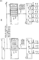
- FIG. 12 is a diagram showing components related to the distribution of detection signals in the servo system 400 shown in FIG.
- the encoder 31 has two systems of input units 312 and 312a.
- the destination of the detection signal from the sensor is the servo driver 2 connected to the encoder
- a cable from the sensor is connected to the input unit 312.
- the destination of the detection signal from the sensor is the servo driver 2a
- the cable from the sensor is connected to the input unit 312a.
- Each of the input units 312 and 312a gives information for identifying a destination to the signal input from the sensor.
- information given to the signal input to the input unit 312 is “# 1”
- information given to the signal input to the input unit 312a is “# 2”.
- “# 1” indicates a signal sent to the servo driver 2.
- “# 2” indicates a signal sent to the servo driver 2a.
- the encoders 31 and 31a generate information indicating the servo driver corresponding to the destination of the detection signal.
- the encoder 31 and 31a when each of the encoders 31 and 31a receives a detection signal from a sensor assigned to a servo driver that drives a motor whose operation is detected by the encoder, the encoder 31 and 31a provide information for associating the servo driver with a destination. Generate. On the other hand, when each of the encoders 31 and 31a receives a detection signal from a sensor assigned to another servo driver, the encoder 31 or 31a generates information for associating the other servo driver with the destination, and sends the information to the corresponding servo driver. Send that information.
- Each of the servo drivers 2 and 2a receives the detection signal from the corresponding encoder, and determines whether the information given to the detection signal is “# 1” or “# 2”. When the assigned information is “# 1”, the servo driver 2 processes the signal. On the other hand, when the assigned information is “# 2”, the servo driver 2 transfers the signal to the servo driver 2a. On the other hand, when the assigned information is “# 1”, the servo driver 2 a transfers the signal to the servo driver 2, while when the assigned information is “# 2”, the servo driver 2 a processes the signal. To do.
- each servo driver determines whether to process the detection signal or transfer the detection signal to another servo driver.
- Information indicating the servo driver corresponding to the destination of the detection signal ("# 1" or " # 2 ").
- a cable from each sensor is connected to a closer encoder among a plurality of encoders, and a detection signal from the sensor is converted into a servo that requires the detection signal. Can be sent to the driver. Thereby, the wiring connected to the sensor can be further shortened.
- Information indicating the servo driver corresponding to the destination of the detection signal may be held by a device (servo driver or PLC) higher than the encoder.
- the servo driver generates the information.
- FIG. 13 is a diagram illustrating components related to the distribution of detection signals in the servo system 500 according to the fifth embodiment. Since the overall configuration of servo system 500 is equivalent to the overall configuration of servo system 400 (see FIG. 9), detailed description will not be repeated.
- the encoder 31 includes an input unit 312.
- the input unit 312 of the encoder 31 has input terminals M1 to M3 for inputting detection signals.
- a cable 72 from the limit sensor 62 is connected to the input terminal M1.
- a cable 73a from the limit sensor 63a is connected to the input terminal M2.
- a cable 74 from the fully closed sensor 64 is connected to the input terminal M3.
- the encoder 31a includes an input unit 312.
- the input unit 312 of the encoder 31a has input terminals N1 to N5 for inputting detection signals.
- a cable 71 from the origin sensor 61 is connected to the input terminal N1.
- a cable 71a from the origin sensor 61a is connected to the input terminal N2.
- a cable 72a from the limit sensor 62a is connected to the input terminal N3.
- a cable 73 from the limit sensor 63 is connected to the input terminal N4.
- a cable 74a from the fully closed sensor 64a is connected to the input terminal N5.
- the input unit 312 transmits, for each detection signal, information indicating to which input terminal the detection signal is input, together with the detection signal or independently.
- Information indicating that the detection signal is input to the input terminal M1 is represented as ⁇ M1>.
- the input unit 312 gives information ⁇ M1> to the detection signal DET2.
- the detection signal DET2 to which the information ⁇ M1> is given is represented as DET2 ⁇ M1>.
- the servo drivers 2 and 2a use information recording units 25 and 25a in which information indicating the destination of the detection signal input to the input terminal (that is, the servo driver to process the detection signal) is recorded. Including.
- the information is recorded in advance in the information recording units 25 and 25a as tables 22 and 22a, respectively.
- the table 22 includes a correspondence indicating that the destination of the detection signal input to the input terminal M1 is the servo driver 2, for example.
- the correspondence between the input terminal M1 and the servo driver 2 is represented as “M1-servo driver 2”.
- each of the servo drivers 2 and 2a can generate information indicating the servo driver corresponding to the destination of each detection signal (for example, information indicating that the destination of the detection signal DET2 is the servo driver 2).
- each servo driver When each servo driver receives a detection signal from a sensor assigned to the servo driver, each servo driver processes the detection signal. As an example, the destination of the detection signal DET2 is the servo driver 2. For this reason, the servo driver 2 processes the detection signal DET2.
- each servo driver when each servo driver receives a detection signal from a sensor assigned to a servo driver different from the servo driver, the servo driver generates information for associating the other servo driver with the destination and detects it. Send signals and information.
- Each of the servo drivers 2 and 2a gives the information to the detection signal, and transmits the detection signal to which the information is given to a servo driver different from the servo driver.
- each of the servo drivers 2 and 2a receives information indicating the corresponding servo driver and the detection signal, and processes the detection signal with the servo driver, or passes the detection signal to another servo driver. And decide whether to transfer.
- the destination of the detection signal DET3a is the servo driver 2a.
- the servo driver 2 gives information ⁇ servo driver 2a> corresponding to the destination of the detection signal DET3a to the detection signal DET3a.
- the detection signal DET3a to which the information ⁇ servo driver 2a> is given is represented as DET3a ⁇ servo driver 2a>.
- the servo driver 2 transmits DET3a ⁇ servo driver 2a> to the servo driver 2a. Therefore, according to the fifth embodiment, the same effect as that of the fourth embodiment can be obtained.
- the detection signal and the information may be transmitted continuously or may be transmitted at time intervals.
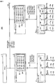
- FIG. 14 is a diagram illustrating components related to the distribution of detection signals in the servo system 501 according to the first modification of the fifth embodiment.
- servo drivers 2 and 2a are connected to PLC 1 in parallel.
- Servo drivers 2 and 2a have information recording units 25 and 25a, respectively.
- a common table 23 is recorded in advance in the information recording units 25 and 25a. That is, the information recorded in the information recording unit is common between the servo drivers 2 and 2a.
- the table 23 is information indicating the destination of the detection signal (that is, the servo driver that should process the detection signal) for all input terminals of the input unit 312 of the servo driver 2 and all input terminals of the input unit 312 of the servo driver 2a. including. That is, this information is information for specifying the destination for each detection signal.
- FIG. 14 only the detection signal received by the encoder 31 is shown in order to prevent the drawing from becoming complicated.
- Each of the servo drivers 2 and 2a processes the detection signal with the servo driver based on the information recorded in the information recording unit (25 and 25a) or transfers the detection signal to another servo driver. Decide what to do.
- information indicating that the signal has been input to the input terminal M2 is represented as ⁇ M2>.
- the detection signal DET3a to which the information ⁇ M2> is given is represented as DET3a ⁇ M2>.
- the servo driver 2 receives DET3a ⁇ M2> from the encoder 31.
- the servo driver 2 gives information ⁇ servo driver 2a> indicating that the destination of the detection signal DET3a is the servo driver 2a to the detection signal DET3a ⁇ M2>.
- the servo driver 2 transmits DET3a ⁇ M2> [servo driver 2a].
- DET3a ⁇ M2> [servo driver 2a] is a detection signal DET3a ⁇ M2> to which information [servo driver 2a] is added.
- each of the servo drivers 2 and 2a checks the destination information given to the detection signal transmitted through the communication cable 42.
- the detection signal DET3a ⁇ M2> is given [servo driver 2a] as destination information. Therefore, the servo driver 2a can receive the detection signal DET3a ⁇ M2> [servo driver 2a]. That is, the detection signal DET3a ⁇ M2> is transferred from the servo driver 2 to the servo driver 2a.
- Servo driver 2a receives detection signal DET3a ⁇ M2> [servo driver 2a] and refers to table 23.
- the servo driver 2a is registered as a servo driver corresponding to the information ⁇ M2> given to the received detection signal DET3a.
- the servo driver 2a can determine that the received detection signal DET3a should be processed by the servo driver 2a. Since the other processes in the first modification of the fifth embodiment are the same as the processes in the fifth embodiment, detailed description will not be repeated. According to Modification 1 of Embodiment 5, the same effect as that of Embodiment 4 can be obtained.
- the common table 23 is recorded in the information recording unit (25, 25a) of each servo driver. That is, the same information is held in each servo driver.
- each servo driver can transfer the detection signal when the information added to the transmitted detection signal is information that is not registered in the servo driver. In the case of such a configuration, each servo driver processes the detection signal when the information added to the transmitted detection signal is information registered in the servo driver.
- FIG. 15 is a diagram illustrating components related to the distribution of detection signals in the servo system 502 according to the second modification of the fifth embodiment.
- the configuration of the servo system 502 shown in FIG. 15 is the same as the configuration of the servo system 500 shown in FIG. However, the contents of the table recorded in the information recording unit are different from the configuration shown in FIG. Information indicating that the destination of the detection signal is the servo driver is recorded in the table.
- the table 24 is recorded in the information recording unit 25 of the servo driver 2.
- the table 24 includes information on terminals provided to the detection signal whose destination is the servo driver 2. This information is information indicating that the destination of the detection signal is the servo driver 2. Therefore, when the information given to the received detection signal is information indicating the terminals M1, M3, N1, and N4, the servo driver 2 processes the detection signal. On the other hand, when a detection signal to which information (information not corresponding to the destination indicated by the information included in the table 24) indicating a terminal different from the above terminal is sent to the servo driver 2, the servo driver 2 detects the detection signal. The signal is transferred to the servo driver 2a.
- the servo driver 2 receives the detection signal DET3a ⁇ M2> from the encoder 31. Information on the terminal M2 is not included in the table 24. Therefore, the servo driver 2 transfers the detection signal DET3a ⁇ M2> to the servo driver 2a.
- a table 24a is recorded in the information recording unit 25a of the servo driver 2a.
- the table 24a includes information on terminals provided to a detection signal whose destination is the servo driver 2a. That is, when the information given to the detection signal is information indicating the terminals M2, N2, N3, and N5, the servo driver 2a processes the detection signal. Therefore, the servo driver 2a processes the detection signal DET3a ⁇ M2> transferred from the servo driver 2.
- the servo driver 2a receives the detection signal DET1 ⁇ N1> from the encoder 31a and transfers the detection signal DET1 ⁇ N1> to the servo driver 2.
- the servo driver 2a receives the detection signal DET3 ⁇ N4> from the encoder 31a and transfers the detection signal DET3 ⁇ N4> to the servo driver 2.
- the fifth embodiment and its modifications 1 and 2 can be applied even to a system in which the number of servo drivers is three or more. In either case, the transfer destination of the detection signal from each servo driver is determined in one way. In the case of the fifth embodiment and the first modification thereof, one destination of the detection signal is determined in the table. For example, in Modification 2, a detection signal is transferred from one servo driver to another servo driver. However, when the transfer destination servo driver does not process the detection signal, the servo driver can transfer the detection signal to another servo driver (servo driver determined in advance as the transfer destination).
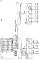
- FIG. 16 is a diagram illustrating components related to the distribution of detection signals in the servo system 600 according to the sixth embodiment.
- the overall configuration of servo system 600 and the configuration of the encoder are the same as the overall configuration of servo system 400 (see FIG. 9) and the configuration of encoders 31 and 31a (see FIG. 13), respectively, and detailed description will not be repeated.
- FIG. 16 only detection signals received by the encoder 31 are shown in order to prevent the drawing from becoming complicated.
- the PLC 1 includes an information recording unit 12 in which a table 11 is recorded in advance.
- the table 11 includes information indicating the destination of the detection signal for all input terminals of the input unit 312 of the servo driver 2 and all input terminals of the input unit 312 of the servo driver 2a.
- the PLC 1 generates information indicating the servo driver corresponding to the destination of each detection signal based on the table 11.
- the detection signal DET2 to which the information ⁇ M1> is assigned is represented as DET2 ⁇ M1>.
- the detection signal DET2 to which the information for making the servo driver 2 correspond to the destination of the detection signal DET2 is given is represented as DET2 ⁇ servo driver 2>.
- the servo driver 2 receives DET2 ⁇ M1>, it transmits DET2 ⁇ M1> to the PLC 1 as it is.
- the PLC 1 generates DET 2 ⁇ servo driver 2> based on the table 11 and transmits DET 2 ⁇ servo driver 2> to the servo driver 2.
- DET2 ⁇ servo driver 2> is processed by the servo driver 2.
- the detection signal DET3a to which the information ⁇ M2> is assigned is represented as DET3a ⁇ M2>.
- the detection signal DET3a to which the information for causing the servo driver 2a to correspond to the destination of the detection signal DET3a is given is represented as DET3a ⁇ servo driver 2a>.
- the servo driver 2 receives DET3a ⁇ M2>, it transmits DET3a ⁇ M2> to the PLC 1 as it is.
- the PLC 1 generates DET 3 a ⁇ servo driver 2 a> based on the table 11, and transmits DET 3 a ⁇ servo driver 2 a> to the servo driver 2.
- DET3a ⁇ servo driver 2a> is transferred from the servo driver 2 to the servo driver 2a and processed by the servo driver 2a.
- the same effect as that of the fourth embodiment can be obtained.
- the destination of the detection signal is determined by the encoder.
- Each servo driver processes or transfers a detection signal according to the destination determined by the encoder.
- each servo driver determines whether the detection signal is processed by the servo driver itself or transferred.
- the destination of the detection signal is determined by the PLC.
- Each servo driver processes or transfers a detection signal in accordance with the destination determined by the PLC.
- the PLC 1 causes the servo driver to process the detection signal when each of the servo drivers 2 and 2a receives the detection signal from the sensor assigned to the servo driver.
- the servo driver sends the detection signal to the servo driver.
- the servo driver is controlled to be transferred to another servo driver.
- the detection signal and the information may be transmitted continuously or may be transmitted at time intervals.
- FIG. 17 is a diagram illustrating components related to the distribution of detection signals in the servo system 601 according to the modification of the sixth embodiment. In FIG. 17, only detection signals received by the encoder 31 are shown in order to prevent the drawing from becoming complicated.
- servo drivers 2 and 2a are connected to PLC 1 in parallel.
- the PLC 1 has an information recording unit 12 in which a table 11 is recorded in advance.
- the table 11 includes information indicating the destination of the detection signal input to each input terminal.
- the PLC 1 holds this information and, based on the held information, processes the detection signal by the servo driver for each servo driver or transfers the detection signal to another servo driver. To decide.
- the servo driver 2 inquires of the PLC 1 whether the detection signal can be processed by itself. For example, when the servo driver 2 receives DET2 ⁇ M1>, the servo driver 2 holds the detection signal DET2 instead of transmitting the DET2 ⁇ M1> to the PLC1 as it is, and transmits the information ⁇ M1> to the PLC1. According to Table 11, the servo driver 2 should process the detection signal input to the input terminal M1. Therefore, the PLC 1 notifies the servo driver 2 that the detection signal should be processed. The servo driver 2 processes the detection signal DET2 according to the notification.
- the servo driver 2 when receiving the DET3a ⁇ M2>, for example, the servo driver 2 holds the detection signal DET3a while transmitting the information ⁇ M2> to the PLC1. According to Table 11, the servo driver 2a should process the detection signal input to the input terminal M2. Therefore, the PLC 1 notifies the servo driver 2 that the detection signal should be transferred to the servo driver 2a.
- the servo driver 2 In response to the notification from the PLC 1, the servo driver 2 generates information [servo driver 2a] indicating that the destination of the detection signal DET3a ⁇ M2> is the servo driver 2a.
- the servo driver 2 adds information [servo driver 2a] to the detection signal DET3a ⁇ M2> to generate a detection signal DET3a ⁇ M2> [servo driver 2a]. Then, the servo driver 2 transmits the detection signal DET3a ⁇ M2> [servo driver 2a].
- Each of the servo drivers 2 and 2a checks the destination information given to the detection signal transmitted through the communication cable 42.
- the detection signal DET3a ⁇ M2> is given [servo driver 2a] as destination information. Therefore, the servo driver 2a can receive the detection signal DET3a ⁇ M2> [servo driver 2a]. That is, the detection signal DET3a ⁇ M2> is transferred from the servo driver 2 to the servo driver 2a.
- the servo driver 2a When the servo driver 2a receives the detection signal DET3a ⁇ M2> [servo driver 2a], the servo driver 2a inquires of the PLC 1 whether the detection signal DET3a ⁇ M2> can be processed by itself. The PLC 1 notifies the servo driver 2a that the detection signal should be processed. The servo driver 2a processes the detection signal DET3a according to the notification.
- At least one of the encoders 31 and 31a is configured to be connectable to an electric device (for example, a lighting device) through a cable, and supplies power to the electric device through the cable. Also good. Further, as described in the third embodiment, at least one of the encoders 31 and 31a is configured to be connectable to an electric device (for example, an imaging device) through a cable, and a control signal for controlling the electric device is provided. It may be output to an electrical device through a cable.
- an electric device for example, a lighting device
- an electric device for example, an imaging device
- the number of groups is not limited to two.
- this embodiment can be applied to a servo system having more than two groups by increasing the number of encoder input units to more than two (increasing the number of input channels).
- each group was shown as a structure of each group.
- the configuration of each group may be either a configuration based on the first embodiment or a configuration based on the second embodiment.
- the motor and the encoder may be integrated or separated.
- the information recording unit is mounted on a device that determines the destination of the detection signal. Specifically, in the fifth embodiment (and its modifications 1 and 2), the information recording unit is provided in the servo drivers 2 and 2a. In the sixth embodiment, the information recording unit is provided in the PLC 1. However, the information recording unit may be provided in the servo system. Therefore, the information recording unit may be provided independently of the PLC or the servo driver. That is, the information recording unit may be provided in any part of the servo system.
Landscapes
- Engineering & Computer Science (AREA)
- Human Computer Interaction (AREA)
- Manufacturing & Machinery (AREA)
- Physics & Mathematics (AREA)
- General Physics & Mathematics (AREA)
- Automation & Control Theory (AREA)
- Microelectronics & Electronic Packaging (AREA)
- Power Engineering (AREA)
- Transmission And Conversion Of Sensor Element Output (AREA)
- Control Of Position Or Direction (AREA)
- Programmable Controllers (AREA)
- Arrangements For Transmission Of Measured Signals (AREA)
Abstract
サーボシステムにおいて、センサの配線の作業性を向上させることが可能な構成を提供する。エンコーダ(31)は、サーボドライバ(2)により駆動されるモータ(30)の動作を検出して、検出された動作を示すフィードバック信号(FB)を生成する。さらにエンコーダ(31)は、モータ(30)により駆動される対象物(53)を検出するセンサ(61~64)から出力された検出信号(DET1~DET4)を、センサケーブル(71~74)を介して受ける。エンコーダ(31)は、フィードバック信号(FB)および入力された検出信号(DET1~DET4)を外部に出力する。
Description
本発明は、エンコーダおよびサーボシステムに関する。
サーボシステムは、一般に、モータと、サーボアンプと、コントローラとを有する。たとえば特開2010-67036号公報(特許文献1)に開示されたサーボシステムは、上位マスタ(コントローラ)と複数のサーボアンプとを備える。外部センサ(たとえば温度センサ)は、ケーブルによって、複数のサーボアンプのうちの1つに接続される。
サーボシステムが適用される場所において、レイアウト等の理由により、サーボドライバがサーボモータから離れている場合がある。このような場合には、サーボドライバとサーボモータとの間をつなぐケーブルに、比較的長いケーブルが必要である。
モータによって駆動される対象物(たとえば加工対象物)の動きを検出するためのセンサは、その対象物の近くに配置されなければならない。すなわち、センサは、モータの近傍に設置される。
したがって、モータとサーボドライバとの間の距離が大きいと、センサとサーボドライバとを接続するケーブルも長くなる。センサとサーボドライバとを接続するケーブルが長くなると、たとえば、ケーブルの配線作業(たとえばケーブルの接続あるいは引回し等)に大きな手間を要するといった問題が発生する。
本発明の目的は、サーボシステムにおいて、センサの配線の作業性を向上させることが可能な構成を提供することである。
本発明のある局面に係るエンコーダは、サーボドライバにより駆動されるモータの動作を検出して、検出された動作を示すフィードバック信号を生成する信号生成部と、モータにより駆動される対象物を検出するセンサから出力された検出信号を、センサケーブルを介して受ける入力部と、信号生成部で生成されたフィードバック信号、および入力部に入力された検出信号を外部に出力するための通信部とを備える。
好ましくは、通信部は、フィードバック信号および検出信号を、共通の通信ケーブルで送信するための出力端子を有する。
好ましくは、エンコーダは、電気機器とケーブルを通じて接続可能に構成され、ケーブルを通じて電気機器に電力を供給するための電源端子をさらに備える。
好ましくは、エンコーダは、電気機器とケーブルを通じて接続可能に構成され、電気機器を制御するための制御信号を、ケーブルを通じて電気機器に出力するための制御端子をさらに備える。
好ましくは、エンコーダは、複数のサーボドライバが互いに通信可能な状態での使用に対応した動作モードを有する。通信部は、当該動作モードにおいて、検出信号の宛先に対応するサーボドライバを示す情報を送信する。
本発明の他の局面に係るサーボシステムは、上記のいずれかに記載のエンコーダと、モータと、モータを駆動するためのサーボドライバと、モータにより駆動される対象物を検出するセンサと、センサからの検出信号をエンコーダに伝送するためのセンサケーブルとを備える。
本発明のさらに他の局面に係るサーボシステムは、第1および第2のモータと、第1および第2のモータをそれぞれ駆動する第1および第2のサーボドライバと、第1および第2のモータにそれぞれ割り当てられて、割り当てられたモータにより駆動される対象物を検出して、検出信号を出力する第1および第2のセンサと、第1のモータの動作を示すフィードバック信号を、第1のサーボドライバに送るとともに、センサケーブルを介して第1のセンサまたは第2のセンサからの検出信号を受ける第1のエンコーダと、第2のモータの動作を示すフィードバック信号を、第2のサーボドライバに送るとともに、センサケーブルを介して第1のセンサまたは第2のセンサからの検出信号を受ける第2のエンコーダとを備える。第1および第2のエンコーダの各々は、当該エンコーダによって動作が検出されるモータを駆動するサーボドライバに割り当てられたセンサから検出信号を受けた場合には、検出信号を送信するとともに、検出信号とともにまたは独立に、検出信号の宛先に対応する当該サーボドライバを示す情報を送信する。第1および第2のエンコーダの各々は、別のサーボドライバに割り当てられたセンサから検出信号を受けた場合には、検出信号を送信するとともに、検出信号とともにまたは独立に、検出信号の宛先に対応する当該別のサーボドライバを示す情報を送信する。第1および第2のサーボドライバの各々は、各サーボドライバに接続されたエンコーダからの情報に基づいて、検出信号を処理するか、または、検出信号を当該サーボドライバとは別のサーボドライバへと転送するかを決定する。
好ましくは、第1および第2のサーボドライバの各々が、検出信号を処理するか、または、検出信号を別のサーボドライバへと転送するかを、検出信号の宛先に対応するサーボドライバを示す情報に基づいて決定する。
好ましくは、第1および第2のサーボドライバの各々は、対応するサーボドライバを示す情報と、検出信号とを受信して、検出信号を当該サーボドライバで処理するか、または、検出信号を別のサーボドライバへと転送するかを決定する。
好ましくは、第1および第2のエンコーダの各々は、当該エンコーダによって動作が検出されるモータを駆動するサーボドライバに割り当てられたセンサから検出信号を受けた場合には、当該サーボドライバを宛先に対応させる情報を生成し、別のサーボドライバに割り当てられたセンサから検出信号を受けた場合には、当該別のサーボドライバを宛先に対応させる情報を生成して、対応するサーボドライバに情報を送信する。
好ましくは、第1および第2のサーボドライバの各々は、当該サーボドライバとは別のサーボドライバに割り当てられたセンサからの検出信号を受けた場合には、当該別のサーボドライバを宛先に対応させる情報を生成して検出信号と情報とを送信する。
好ましくは、サーボシステムは、上記情報が予め記録される情報記録部を有する。第1および第2のサーボドライバの各々は、情報記録部に記録されている情報に基づいて、検出信号を当該サーボドライバで処理するか、または、検出信号を別のサーボドライバへと転送するかを決定する。
好ましくは、第1および第2のサーボドライバの各々は、情報記録部を有する。情報記録部に記録される情報は、第1および第2のサーボドライバの間で共通であり、かつ、検出信号ごとに宛先を特定する情報である。
好ましくは、第1および第2のサーボドライバの各々は、検出信号の宛先が当該サーボドライバであることを示す情報が記録された情報記録部を有し、情報で示される宛先に該当しない検出信号を受信した場合には、当該検出信号を別のサーボドライバに転送する。
好ましくは、サーボシステムは、第1および第2のサーボドライバを監視する監視装置をさらに備える。監視装置は、第1および第2のサーボドライバの各々が、当該サーボドライバに割り当てられたセンサからの検出信号を受けた場合には、当該サーボドライバが検出信号を処理するように当該サーボドライバを制御し、第1および第2のサーボドライバの各々が、当該サーボドライバとは別のサーボドライバに割り当てられたセンサからの検出信号を受けた場合には、当該サーボドライバが検出信号を当該別のサーボドライバに転送するように当該サーボドライバを制御する。
好ましくは、サーボシステムは、第1および第2のサーボドライバを監視する監視装置をさらに備える。監視装置は、検出信号を処理すべきサーボドライバを決定して、その決定されたサーボドライバを宛先に対応させる前記情報を生成する。
好ましくは、監視装置は、第1および第2のサーボドライバの各々が検出信号を受けた場合に、検出信号を受けたサーボドライバに対して、上記対応するサーボドライバを示す情報を送信する。
好ましくは、検出信号には、検出信号の宛先に対応するサーボドライバを示す情報が付与される。
好ましくは、検出信号と、検出信号の宛先に対応するサーボドライバを示す情報とは、連続的に送信される。
好ましくは、検出信号と、検出信号の宛先に対応するサーボドライバを示す情報とは、時間的間隔をおいて送信される。
好ましくは、第1および第2のエンコーダのうちの少なくとも一方は、電気機器とケーブルを通じて接続可能に構成され、ケーブルを通じて電気機器に電力を供給する。
好ましくは、第1および第2のエンコーダのうちの少なくとも一方は、電気機器とケーブルを通じて接続可能に構成され、電気機器を制御するための制御信号を、ケーブルを通じて電気機器に出力する。
本発明によれば、サーボシステムにおいて、センサの配線の作業性を向上させることが可能になる。また配線作業の煩雑性を削減することができる。さらにケーブルに要するコストおよび配線作業に要するコストも削減することができる。
以下、本発明の実施の形態について、図面を参照しながら詳細に説明する。なお、図中同一または相当部分には同一符号を付して、その説明は繰り返さない。
以下では、サーボシステムの一つの例示的形態として、産業用システムを示す。しかしながら、本発明に係るサーボシステムの用途は特に限定されるものではない。
[一般的構成]
図1は、一般的なサーボシステムの構成例を概略的に示すブロック図である。図1を参照して、サーボシステム900は、PLC(Programmable Logic Controller)1と、サーボドライバ2と、サーボモータ3と、カップリング51と、ねじ軸52と、精密ステージ53と、リニアスケール54と、原点センサ61と、限界センサ62,63と、フルクローズドセンサ64とを備える。
図1は、一般的なサーボシステムの構成例を概略的に示すブロック図である。図1を参照して、サーボシステム900は、PLC(Programmable Logic Controller)1と、サーボドライバ2と、サーボモータ3と、カップリング51と、ねじ軸52と、精密ステージ53と、リニアスケール54と、原点センサ61と、限界センサ62,63と、フルクローズドセンサ64とを備える。
PLC1は、サーボドライバ2に指令信号CMを出力する。PLC1は、予め準備されたプログラムに従う処理を実行することによって、たとえばサーボドライバ2の監視装置として機能する。
サーボドライバ2は、PLC1から指令信号CMを受ける。さらにサーボドライバ2は、サーボモータ3からフィードバック信号FBを受けるとともに、原点センサ61、限界センサ62,63あるいはフルクローズドセンサ64から出力される検出信号(DET1~DET4)を受ける。サーボドライバ2は、これらの信号に応じてサーボモータ3を駆動する。より具体的には、サーボドライバ2はサーボモータ3の駆動電流Iを制御する。
サーボモータ3は、モータ30と、エンコーダ39とを含む。モータ30は、たとえばACサーボモータである。モータ30は、サーボドライバ2からの駆動電流Iを、電源ケーブル40を介して受ける。エンコーダ39は、モータ30の動作を検出する。エンコーダ39は、検出された動作を示すフィードバック信号FBを、エンコーダケーブル41を介してサーボドライバ2に出力する。
カップリング51は、モータ30の回転軸301と、ねじ軸52とを結合する。精密ステージ53は、モータ30の回転軸301の回転に応じて、ねじ軸52の軸方向(図1において両矢印で示す)に移動する。すなわち精密ステージ53は、モータ30により駆動される対象物である。精密ステージ53の移動量および移動方向は、モータ30の回転数および回転方向に基づいて制御される。図1に示すように、たとえば精密ステージ53に、ワーク8が載せられている。
原点センサ61および限界センサ62,63は、精密ステージ53の位置を検出するために、ねじ軸52に沿って設置される。原点センサ61および限界センサ62,63は、精密ステージ53を検出したことを示す検出信号DET1~DET3を出力する。
たとえば、原点センサ61および限界センサ62,63は、精密ステージ53の存在をオン/オフによって示すセンサである。このようなセンサには、光電センサ、近接センサ、ファイバセンサ等を用いることができる。原点センサ61がオンするときの精密ステージ53の位置が精密ステージ53の原点に対応する。限界センサ62,63がオンする時の精密ステージ53の位置は、精密ステージ53の移動可能範囲の両端に対応する。たとえば限界センサ62あるいは限界センサ63がオンした場合、モータ30が停止することで精密ステージ53が停止してもよい。
原点センサ61および限界センサ62,63に画像センサを用いてもよい。この場合、検出信号DET1~DET3は、画像信号である。
リニアスケール54は、ねじ軸52の軸方向に沿って設置される。リニアスケール54は、たとえば反射型光電式のガラススケールであって、等ピッチのスリット541が設けられている。
フルクローズドセンサ64は、精密ステージ53に設置されて、精密ステージ53と一体的に移動する。フルクローズドセンサ64は、発光部および受光部(いずれも図示せず)を有する。発光部から出射された光は、リニアスケール54のスリット541で反射されて、受光部上に干渉縞を生成する。精密ステージ53が移動すると干渉縞も移動するため、受光部からの出力信号の強度は、精密ステージ53の移動に応じて変化する。したがって、出力信号の強度変化を監視することにより、精密ステージ53の移動量を求めることができる。フルクローズドセンサ64は、精密ステージ53の移動量を算出するための検出信号DET4を出力する。
検出信号DET1~DET4は、それぞれ、ケーブル71~74を介してサーボドライバ2に送られる。ケーブル71~74は、各センサとサーボドライバ2とを接続するセンサケーブルである。ただしセンサケーブルは、センサとPLC1とを接続するケーブルであってもよい。
モータ30の動きを検出するためのエンコーダ39、および、モータ30によって駆動される対象物(図1の例では精密ステージ53)の動きを検出するためのセンサ(原点センサ61、限界センサ62,63およびフルクローズドセンサ64)は、モータ30の近傍に設置される。
一方、サーボドライバ2は、PLC1からの指令、およびエンコーダ39および各センサからの信号を受けることで、モータ30を遠隔的に制御することができる。このため、サーボドライバ2は、モータ30の近傍に設置されていなくてもよい。したがって、サーボドライバ2がサーボモータ3から離れて設置されることがある。
たとえば設置場所でのレイアウト等の要因により、サーボドライバ2とサーボモータ3との間の距離が長くなることが起こり得る。このために、電源ケーブル40およびエンコーダケーブル41も長くなる。したがって、たとえば、長さが、3m、5m、10m、・・・、100mといった電源ケーブル40およびエンコーダケーブル41が準備される。
サーボドライバ2とサーボモータ3との間の距離が長くなると、各センサとサーボドライバ2とを接続するためのケーブル71~74も長くなる。各センサとサーボドライバ2とを接続するためのケーブルが長いと、たとえば、そのケーブルの接続あるいは引き回し当の作業に手間がかかる。つまり配線作業の煩雑性が増大する。また、長いケーブルを使用することによってケーブルに要するコストが増大するとともに、配線作業に伴うコストも増大する。センサの数が多くなるほど、このような問題が顕著になる。
本発明の実施の形態によれば、サーボドライバ2とサーボモータ3との間の距離が長い場合にも、センサの配線が長くなることを回避することができる。以下、各実施の形態について詳細に説明する。
[実施の形態1]
図2は、本発明の実施の形態1に係るサーボシステムの構成を概略的に示すブロック図である。図1および図2を参照して、本発明の実施の形態1に係るサーボシステムは、エンコーダ39に代えてエンコーダ31を含む。
図2は、本発明の実施の形態1に係るサーボシステムの構成を概略的に示すブロック図である。図1および図2を参照して、本発明の実施の形態1に係るサーボシステムは、エンコーダ39に代えてエンコーダ31を含む。
本実施の形態において、原点センサ61、限界センサ62,63およびフルクローズドセンサ64は、それぞれケーブル71,72,73,74によってエンコーダ31に接続される。エンコーダ31は、検出信号DET1~DET4を受ける。エンコーダ31は、その検出信号DET1~DET4を、エンコーダケーブル41を介してサーボドライバ2に送る。
なお、サーボシステム100の他の構成は、サーボシステム900の対応する構成と同等であるため、詳細な説明を繰り返さない。
図3は、図2に示すエンコーダ31の構成を概略的に示すブロック図である。図3を参照して、エンコーダ31は、信号生成部311と、入力部312と、A/D(アナログ-デジタル)変換部313と、通信部314とを含む。
信号生成部311は、サーボドライバ2により駆動されるモータ30の動作を検出して、モータ30の検出された動作を示すフィードバック信号FBを生成する。フィードバック信号FBは通信部314に出力される。
フィードバック信号FBには、たとえばモータ30の回転軸301の回転位置(角度)についての情報、回転軸301の回転速度についての情報、回転軸301の回転方向についての情報などが含まれる。信号生成部311の構成には、たとえば公知のインクリメンタル型またはアブソリュート型の構成を適用することができるため、詳細な説明を繰り返さない。
入力部312は、ケーブル71~74に接続される。入力部312は、たとえば配線を接続するための端子台またはコネクタである。入力部312は、ケーブル71~74を介して、各センサ(図2参照)からの検出信号DET1~DET4を受ける。すなわち、入力部312は、エンコーダ31が検出信号DET1~DET4を受けるための入力インターフェイスとして機能する。検出信号DET1~DET4は、入力部312からA/D変換部313に出力される。
A/D変換部313は、入力部312からの検出信号DET1~DET4をA/D変換して、その変換されたデジタル信号を通信部314に出力する。
通信部314は、サーボドライバ2と通信するためのインターフェイスである。本実施の形態において、通信部314は、エンコーダケーブル41を介して、フィードバック信号FBおよび検出信号DET1~DET4をサーボドライバ2に送る。
この実施の形態では、通信部314からのフィードバック信号FBおよび検出信号DET1~DET4の送信には、シリアル通信が適用される。これにより、ケーブルに含まれる信号線の本数を少なくすることができる。エンコーダケーブル41によるシリアル通信には、たとえばRS-232C(Recommended Standards 232)、RS-422、あるいはRS-485などの公知の通信規格を採用することができる。
RS-232C、RS-422、RS-485は、長距離(通信規格上、RS-232Cでは最大15m、RS-422およびRS-485では最大1.2km)の通信をサポートする規格である。したがって、これらの通信規格を本実施の形態に採用することにより、サーボドライバとサーボモータとの間の距離が大きい場合にも、信号を安定して伝送することができる。
図4は、図2に示すエンコーダケーブル41の構成例を示した図である。図4(A)は、RS-232Cに準じたエンコーダケーブル41の構成を示した図である。図4(B)は、RS-422に準じたエンコーダケーブル41の構成を示した図である。図4(C)は、RS-485に準じたエンコーダケーブル41の構成を示した図である。
RS-232Cは、全二重通信方式のシリアル通信規格である。図4(A)に示されるように、エンコーダケーブル41は、電源電圧Vccを与える電源ライン411と、接地電位GNDを与える接地ライン412と、2本のデータ伝送ライン413,414とを含む。
サーボモータ3において、通信部314は、通信コントローラ314aと、電源ライン411、接地ライン412、およびデータ伝送ライン413,414にそれぞれ電気的に接続される端子T1~T4とを有する。通信コントローラ314aは、たとえばIC(Integrated Circuit)によって実現される。通信コントローラ314aは、端子T4を介してフィードバック信号FBおよび検出信号DET1~DET4を出力する。すなわち端子T4は、フィードバック信号FBおよび検出信号DET1~DET4を、共通の通信ケーブル(エンコーダケーブル41)で送信するための出力端子である。
端子T4に出力されたフィードバック信号FBおよび検出信号DET1~DET4は、伝送ライン414を伝送される。これらの信号は、サーボドライバ2の通信部21により受信される。
RS-422は、全二重通信または半二重通信方式のシリアル通信規格である。たとえば全二重通信の場合、図4(B)に示されるように、エンコーダケーブル41は、電源ライン411と、接地ライン412と、各々が差動信号を伝送する1対のデータ伝送ラインであるデータ伝送ライン415,416とを含む。このようなエンコーダケーブル41の構成では、エンコーダ31の通信部314は、上記の端子T3,T4に代えて、データ伝送ライン415に電気的に接続される端子T3a,T3bと、データ伝送ライン416に電気的に接続される端子T4a,T4bとを有する。端子T4a,T4bは、フィードバック信号FBおよび検出信号DET1~DET4を、共通の通信ケーブル(エンコーダケーブル41)で送信するための出力端子である。
RS-485は、全二重通信または半二重通信方式のシリアル通信規格である。たとえば半二重通信の場合、図4(C)に示されるように、エンコーダケーブル41は、電源ライン411と、接地ライン412と、差動信号を伝送するための1対のデータ伝送ライン417とを含む。このようなエンコーダケーブル41の構成では、エンコーダ31の通信部314は、データ伝送ライン417に電気的に接続される端子T4a,T4bを有する。図4(B)に示す構成と同じく、端子T4a,T4bは、フィードバック信号FBおよび検出信号DET1~DET4を、共通の通信ケーブル(エンコーダケーブル41)で送信するための出力端子である。
本実施の形態によれば、ケーブル71~74はエンコーダ31に接続される。エンコーダ31および各センサは、いずれもモータ30の近くに配置される。したがって、ケーブル71~74には、より短いケーブルを使用することができる。したがって、センサの配線作業を容易にすることができる。つまり配線作業の煩雑性を削減することができる。さらにケーブルに要するコストおよび配線作業に要するコストも削減することができる。なお、「モータ30の近く」とは、サーボドライバ2との間の距離よりもモータ30との間の距離が短い位置を含む。
さらに、ケーブル71~74を伝送される検出信号DET1~DET4がアナログ信号である場合がある。本実施の形態によれば、図1に示す構成に比べてケーブル71~74を短くできるため、ケーブル71~74を伝送される検出信号DET1~DET4への電磁ノイズの影響を小さくすることができる。これによりサーボシステムの信頼性を高めることができる。
[実施の形態2]
図5は、本発明の実施の形態2に係るサーボシステムの構成を概略的に示すブロック図である。図2および図5を参照して、サーボシステム200は、照明機器81をさらに備える点、およびエンコーダ31に代えてエンコーダ32を含む点において、サーボシステム100と異なる。照明機器81は、ケーブル91を通じてエンコーダ32に接続される電気機器の1つの実現例として図5に示されている。
図5は、本発明の実施の形態2に係るサーボシステムの構成を概略的に示すブロック図である。図2および図5を参照して、サーボシステム200は、照明機器81をさらに備える点、およびエンコーダ31に代えてエンコーダ32を含む点において、サーボシステム100と異なる。照明機器81は、ケーブル91を通じてエンコーダ32に接続される電気機器の1つの実現例として図5に示されている。
図6は、図5に示したエンコーダ32の構成を概略的に示すブロック図である。図3および図6を参照して、エンコーダ32の構成は、出力部325をさらに含む点において、エンコーダ31(図3参照)の構成と異なる。出力部325は、たとえば端子台またはコネクタにより実現可能である。
出力部325は、電源端子T5を有する。ケーブル91は電源端子T5に接続される。言い換えると、電源端子T5は、ケーブル91を通じて照明機器81に接続可能に構成される。電源端子T5から照明機器81に電力Pが供給される。照明機器81は、電力Pを受けて精密ステージ53を照明する。エンコーダ32から照明機器81に供給される電力(破線の矢印で示す)は、たとえば、サーボドライバ2からエンコーダ32(あるいはモータ30でもよい)に供給される電力の一部である。
なお、サーボシステム200およびエンコーダ32の上記以外の構成は、サーボシステム100(図2参照)およびエンコーダ31(図3参照)の対応する構成と同等であるため、詳細な説明を繰り返さない。
照明機器81は、モータ30により駆動される対象物(精密ステージ53)の近くに配置される。すなわち照明機器81は、モータ30の近くに配置される。同じく、エンコーダ32もモータ30の近くに配置される。この実施の形態によれば、照明機器81はケーブル91を介してエンコーダ32に接続される。したがって、照明機器81をサーボドライバ2に接続する場合に必要なケーブルよりも、短いケーブルを用いることができる。
以上のように、実施の形態2によれば、実施の形態1による効果と同じ効果を得ることができる。さらに、実施の形態2によれば、電気機器に接続されるケーブルの長さも短くすることができるので、電気機器の配線作業も容易にすることができる。
なお、エンコーダ32に接続可能な電気機器は、照明機器81に限定されるものではない。サーボシステムの構成、エンコーダ32の出力電流の定格などに基づいて、適切な電気機器を選択することができる。たとえばアクチュエータに用いられるソレノイド等をエンコーダ32に接続することができる。
[実施の形態3]
図7は、本発明の実施の形態3に係るサーボシステムの構成を概略的に示すブロック図である。図5および図7を参照して、サーボシステム300は、撮像装置82をさらに備える点、およびエンコーダ32に代えてエンコーダ33を含む点において、サーボシステム200と異なる。照明機器81および撮像装置82は、ケーブル91を通じてエンコーダ32に接続される電気機器の1つの実現例として図5に示されている。
図7は、本発明の実施の形態3に係るサーボシステムの構成を概略的に示すブロック図である。図5および図7を参照して、サーボシステム300は、撮像装置82をさらに備える点、およびエンコーダ32に代えてエンコーダ33を含む点において、サーボシステム200と異なる。照明機器81および撮像装置82は、ケーブル91を通じてエンコーダ32に接続される電気機器の1つの実現例として図5に示されている。
図8は、図7に示したエンコーダ33の構成を概略的に示すブロック図である。図6および図8を参照して、実施の形態3では、出力部325は、電源端子T5に加えて、電源端子T5aおよび制御端子T6を有する。さらに入力部312は、データ入力端子T7を有する。
撮像装置82に接続されるケーブル92は、電源線92aと、制御線92bと、データ線92cとを含む。電源線92aは、電源端子T5aに接続される。制御線92bは、制御端子T6に接続される。データ線92cは、データ入力端子T7に接続される。
サーボドライバ2は、撮像装置82を制御するための制御信号CTRを出力する。制御信号CTRは、エンコーダケーブル41を介して、エンコーダ33の通信部314に入力される。通信部314は、その制御信号CTRを出力部325に送る。
出力部325は、電源端子T5aから電源線92aを通じて撮像装置82に電力を送る。さらに出力部325は、制御端子T6から制御線92bを通じて撮像装置82に制御信号CTRを送る。言い換えると、制御端子T6は、ケーブル92(制御線92b)を通じて撮像装置82に接続可能に構成され、撮像装置82を制御するための制御信号CTRを、ケーブル92を通じて撮像装置82に出力するための制御端子である。
撮像装置82は、制御信号CTRに応じてワーク8を撮影して、画像データをデータ信号DATとして出力する。データ信号DATは、データ線92cおよびデータ入力端子T7を通じて入力部312に入力される。入力部312はデータ信号DATを通信部314に送る。通信部314は、エンコーダケーブル41を介してサーボドライバ2にデータ信号DATを送信する。
以上のように、実施の形態3によれば、実施の形態1による効果および実施の形態2による効果と同じ効果を得ることができる。特に、実施の形態3によれば、サーボドライバ2により制御される電気機器に接続されるケーブルの長さを短くすることができるので、その電気機器の配線作業も容易にすることができる。
[実施の形態4]
図9は、本発明の実施の形態4に係るサーボシステムの構成を概略的に示すブロック図である。図9を参照して、サーボシステム400は、PLC1と、PLC1によって監視される複数のグループを含む。各グループは、サーボドライバと、そのサーボドライバに割り当てられるサーボモータ、センサおよびエンコーダとにより構成される。図示の都合上、図9では2つのグループが示されている。しかし、グループの数は2に限定されるものではない。
図9は、本発明の実施の形態4に係るサーボシステムの構成を概略的に示すブロック図である。図9を参照して、サーボシステム400は、PLC1と、PLC1によって監視される複数のグループを含む。各グループは、サーボドライバと、そのサーボドライバに割り当てられるサーボモータ、センサおよびエンコーダとにより構成される。図示の都合上、図9では2つのグループが示されている。しかし、グループの数は2に限定されるものではない。
各グループの構成は、実施の形態1(図2参照)に係る構成と同様である。このため、各グループ間で同一または対応する構成要素には、同一または対応する符号が付されている。
原点センサ61、限界センサ62,63およびフルクローズドセンサ64は、サーボモータ3に割り当てられる。一方、原点センサ61a、限界センサ62a,63aおよびフルクローズドセンサ64aは、サーボモータ3aに割り当てられる。
図9に示された形態において、各センサからのケーブルは、そのセンサにより近いエンコーダに接続される。実施の形態1では、各センサからのケーブルは、そのセンサによって検出される対象物を駆動するモータの動作を検出するエンコーダに接続される。たとえば、原点センサ61および限界センサ63は、モータ30によって駆動される精密ステージ53を検出する。したがって、実施の形態1の構成によれば、原点センサ61および限界センサ63は、いずれもエンコーダ31に接続される。
一方、図9に示した構成では、原点センサ61および限界センサ63にとって、エンコーダ31よりもエンコーダ31aのほうがより近くに配置される。したがってこの実施の形態では、原点センサ61からのケーブル71および限界センサ63からのケーブル73は、エンコーダ31aに接続される。複数のエンコーダが配置されることにより、このような構成が実現される。
同じく、限界センサ63aは、モータ30aによって駆動される精密ステージ53aを検出する。したがって実施の形態1の構成によれば、限界センサ63aからのケーブル73aは、エンコーダ31aに接続される。しかしながら図9に示した構成では、限界センサ63aにとって、エンコーダ31aよりもエンコーダ31のほうがより近くに配置される。したがって、この実施の形態では、限界センサ63aからのケーブル73aは、エンコーダ31に接続される。
なお、残りのセンサについても、同様に、エンコーダ31,31aのうち、より近くにあるエンコーダにケーブルを介して接続可能である。ただし、図9に示された構成では、限界センサ62、フルクローズドセンサ64、原点センサ61a、限界センサ62aおよびフルクローズドセンサ64aについては、より近くにあるエンコーダと、そのセンサによって検出される対象物を駆動するモータの動作を検出するエンコーダとが一致している。
より具体的に説明すると、限界センサ62およびフルクローズドセンサ64は、精密ステージ53(対象物)を検出する。これらのセンサにとって、エンコーダ31aよりもエンコーダ31のほうがより近くに配置される。また、精密ステージ53を駆動するモータ30の動作はエンコーダ31によって検出される。つまり、限界センサ62およびフルクローズドセンサ64にとって、より近くにあるエンコーダと、そのセンサによって検出される対象物を駆動するモータの動作を検出するエンコーダとが一致している。したがって、限界センサ62およびフルクローズドセンサ64は、それぞれケーブル72およびケーブル74を介して、エンコーダ31に接続される。
同じく、原点センサ61a、限界センサ62aおよびフルクローズドセンサ64aは、精密ステージ53a(対象物)を検出する。これらのセンサにとって、エンコーダ31よりもエンコーダ31aのほうがより近くに配置される。また、精密ステージ53aを駆動するモータ30aの動作はエンコーダ31aによって検出される。つまり、原点センサ61a、限界センサ62aおよびフルクローズドセンサ64aにとって、より近くにあるエンコーダと、そのセンサによって検出される対象物を駆動するモータの動作を検出するエンコーダとが一致している。したがって、原点センサ61a、限界センサ62aおよびフルクローズドセンサ64aは、それぞれケーブル71a、ケーブル72aおよびケーブル74aを介してエンコーダ31aに接続される。
原点センサ61、限界センサ62,63およびフルクローズドセンサ64は、それぞれ検出信号DET1~DET4を出力する。一方、原点センサ61a、限界センサ62a,63aおよびフルクローズドセンサ64aは、それぞれ検出信号DET1a~DET4aを出力する。
各エンコーダ31,31aは、複数のサーボドライバ2,2aが互いに通信可能な状態での使用に対応した動作モードを有する。たとえば各エンコーダ31,31aは、そのエンコーダに接続されたサーボドライバから、エンコーダケーブルを通じて、動作モード設定のための信号を受けてもよい。
この動作モードにおいて、各エンコーダ31,31aは、検出信号を送信するとともに、検出信号とともにまたは独立に、検出信号の宛先に対応するサーボドライバ(サーボドライバ2,2aのいずれか)を示す情報を送信する。
検出信号DET1~DET4,DET1a~DET4aの各々は、その検出信号を必要とするサーボドライバまで到達する必要がある。サーボドライバ2とサーボドライバ2aとは通信ケーブル42により接続される。サーボドライバ2,2aの各々は、各検出信号の宛先に対応するサーボドライバ(サーボドライバ2,2aのいずれか)を示す情報に基づいて、各エンコーダからの検出信号を、その検出信号を必要とするサーボドライバに伝送する、あるいは、自身で受ける。
より具体的に説明すると、サーボドライバ2は、エンコーダ31から検出信号DET2,DET3aおよびDET4を受ける。検出信号DET2,DET4はサーボドライバ2で処理されるべき信号であるのに対して、検出信号DET3aは、サーボドライバ2aで処理されるべき信号である。したがって、サーボドライバ2は、検出信号DET3aをサーボドライバ2aへと転送する。
同じく、サーボドライバ2aは、エンコーダ31aから検出信号DET1,DET1a,DET2a,DET3,DET4aを受ける。検出信号DET1a,DET2a,DET4aはサーボドライバ2aで処理されるべき信号であるのに対して、検出信号DET1,DET3は、サーボドライバ2で処理されるべき信号である。したがって、サーボドライバ2aは、検出信号DET1およびDET3をサーボドライバ2aへと転送する。
このように検出信号をサーボドライバ間で振り分けるためには、検出信号と、その検出信号の宛先に対応するサーボドライバを示す情報とが互いに関連付けられている必要がある。
図10は、検出信号と、検出信号の宛先に対応するサーボドライバを示す情報との間の関連付けを説明するための図である。図10を参照して、検出信号には、その検出信号の宛先に対応するサーボドライバを示す情報が付与されてもよい(図10(A)参照)。また、検出信号と上記情報とは、互いに関連付けられていれば、別々に送信されてもよい。この場合、検出信号と上記情報とは、連続的に送信されてもよく、あるいは時間的間隔をおいて送信されてもよい。
検出信号と上記情報とが連続的に送信される場合について説明する。サーボドライバ2,2aの各々は、連続して検出信号と上記情報とを受ける。したがって、サーボドライバ2,2aの各々は、検出信号と上記情報とを関連付けることができる(図10(B)参照)。なお、検出信号と上記情報との順序は逆であってもよい。
さらに、検出信号と上記情報とが時間的間隔をおいて送信される場合について説明する。上記の時間的間隔Δtは予め定められている。サーボドライバ2,2aの各々は、検出信号を受ける。サーボドライバ2,2aの各々は、その検出信号を受信したときから時間的間隔Δt経過後に上記情報を受ける。つまり、各サーボドライバは、検出信号の受信から一定のタイミング(Δt)で情報を受信する。したがって、サーボドライバ2,2aの各々は、検出信号と上記情報とを関連付けることができる(図10(C)参照)。あるいは、エンコーダ31,31aの各々は、検出信号と上記情報とに共通の識別番号(図中IDで表す)を付与してもよい。サーボドライバ2,2aの各々は、識別番号に基づいて、検出信号と上記情報とを関連付けることができる(図10(D)参照)。なお、この識別番号は、たとえばシリアル番号であってもよい。
図11は、図9に示すエンコーダ31,31aの構成を概略的に示すブロック図である。図12は、図9に示すサーボシステム400のうち、検出信号の振り分けに関連する構成要素を示す図である。
図11および図12を参照して、エンコーダ31は、2系統の入力部312,312aを有する。センサからの検出信号の宛先が、そのエンコーダに接続されたサーボドライバ2である場合、そのセンサからのケーブルが入力部312に接続される。一方、センサからの検出信号の宛先が、サーボドライバ2aである場合、そのセンサからのケーブルが入力部312aに接続される。
入力部312,312aの各々は、センサから入力された信号に、宛先を識別する情報を付与する。理解を容易にするため、一例として、入力部312に入力された信号に付与される情報を「#1」とし、入力部312aに入力された信号に付与される情報を「#2」とする。「#1」は、サーボドライバ2に送られる信号を示す。一方、「#2」は、サーボドライバ2aに送られる信号を示す。このように、エンコーダ31,31aは、検出信号の宛先に対応するサーボドライバを示す情報を生成する。
言い換えると、エンコーダ31,31aの各々は、当該エンコーダによって動作が検出されるモータを駆動するサーボドライバに割り当てられたセンサから検出信号を受けた場合には、当該サーボドライバを宛先に対応させる情報を生成する。一方、エンコーダ31,31aの各々は、別のサーボドライバに割り当てられたセンサから検出信号を受けた場合には、当該別のサーボドライバを宛先に対応させる情報を生成して、対応するサーボドライバにその情報を送信する。
サーボドライバ2,2aの各々は、対応するエンコーダからの検出信号を受けて、その検出信号に付与された情報が「#1」および「#2」のいずれであるかを判断する。サーボドライバ2は、付与された情報が「#1」の場合、その信号を処理する一方で、付与された情報が「#2」の場合、その信号をサーボドライバ2aへと転送する。これに対し、サーボドライバ2aは、付与された情報が「#1」の場合、その信号をサーボドライバ2へと転送する一方で、付与された情報が「#2」の場合、その信号を処理する。
言い換えると、各サーボドライバは、検出信号を処理するか、または、検出信号を別のサーボドライバへと転送するかを、検出信号の宛先に対応するサーボドライバを示す情報(「#1」または「#2」)に基づいて決定する。
このように、実施の形態4によれば、各センサからのケーブルを、複数のエンコーダのうちのより近くのエンコーダに接続して、そのセンサからの検出信号を、その検出信号を必要とするサーボドライバに送信することができる。これによりセンサに接続される配線をより短くすることができる。
[実施の形態5]
検出信号の宛先に対応するサーボドライバを示す情報は、エンコーダよりも上位の装置(サーボドライバまたはPLC)が有してもよい。実施の形態5では、サーボドライバが上記情報を生成する。
検出信号の宛先に対応するサーボドライバを示す情報は、エンコーダよりも上位の装置(サーボドライバまたはPLC)が有してもよい。実施の形態5では、サーボドライバが上記情報を生成する。
図13は、実施の形態5に係るサーボシステム500のうち、検出信号の振り分けに関連する構成要素を示す図である。サーボシステム500の全体構成は、サーボシステム400(図9参照)の全体構成と同等であるため、詳細な説明を繰り返さない。
図13を参照して、エンコーダ31は入力部312を備える。エンコーダ31の入力部312は、検出信号を入力するための入力端子M1~M3を有する。入力端子M1には、限界センサ62からのケーブル72が接続される。入力端子M2には、限界センサ63aからのケーブル73aが接続される。入力端子M3には、フルクローズドセンサ64からのケーブル74が接続される。
同じく、エンコーダ31aは入力部312を備える。エンコーダ31aの入力部312は、検出信号を入力するための入力端子N1~N5を有する。入力端子N1には、原点センサ61からのケーブル71が接続される。入力端子N2には、原点センサ61aからのケーブル71aが接続される。入力端子N3には、限界センサ62aからのケーブル72aが接続される。入力端子N4には、限界センサ63からのケーブル73が接続される。入力端子N5には、フルクローズドセンサ64aからのケーブル74aが接続される。
入力部312は、各検出信号について、その検出信号がどの入力端子に入力されたものかを示す情報を、検出信号とともにまたは独立に送信する。検出信号が入力端子M1に入力されたことを示す情報を<M1>と表す。入力部312は、情報<M1>を検出信号DET2に付与する。情報<M1>が付与された検出信号DET2をDET2<M1>と表す。
サーボドライバ2,2aは、各入力端子について、その入力端子に入力された検出信号の宛先(すなわち、その検出信号を処理すべきサーボドライバ)を示す情報が記録された情報記録部25,25aを含む。情報記録部25,25aには、前記の情報がそれぞれテーブル22,22aとして予め記録されている。テーブル22は、たとえば入力端子M1に入力される検出信号の宛先がサーボドライバ2であることを示す対応関係を含む。図13では、入力端子M1とサーボドライバ2との間の対応関係を「M1-サーボドライバ2」と表す。これにより、サーボドライバ2,2aの各々は、各検出信号の宛先に対応するサーボドライバを示す情報(たとえば検出信号DET2の宛先がサーボドライバ2であることを示す情報)を生成することができる。
各サーボドライバは、当該サーボドライバに割り当てられたセンサからの検出信号を受けた場合には、その検出信号を処理する。一例として、検出信号DET2の宛先はサーボドライバ2である。このため、サーボドライバ2は、検出信号DET2を処理する。
一方で、各サーボドライバは、当該サーボドライバとは別のサーボドライバに割り当てられたセンサからの検出信号を受けた場合には、当該別のサーボドライバを宛先と対応させる情報を生成して、検出信号と情報とを送信する。サーボドライバ2,2aの各々は、上記情報を検出信号に付与して、上記情報が付与された検出信号を当該サーボドライバとは別のサーボドライバに送信する。
言い換えると、サーボドライバ2,2aの各々は、対応するサーボドライバを示す情報と、検出信号とを受信して、検出信号を当該サーボドライバで処理するか、または、検出信号を別のサーボドライバへと転送するかを決定する。
一例として、検出信号DET3aの宛先はサーボドライバ2aである。このため、サーボドライバ2は、検出信号DET3aの宛先に対応させる情報<サーボドライバ2a>を検出信号DET3aに付与する。情報<サーボドライバ2a>が付与された検出信号DET3aをDET3a<サーボドライバ2a>と表す。サーボドライバ2は、DET3a<サーボドライバ2a>をサーボドライバ2aに送信する。したがって、実施の形態5によれば、実施の形態4による効果と同じ効果を得ることができる。
なお、検出信号の宛先に対応するサーボドライバを示す情報がその検出信号に付与される場合について説明した。しかし、図10に示すように、検出信号と上記情報とは、連続的に送信されてもよく、あるいは時間的間隔をおいて送信されてもよい。
[実施の形態5の変形例1]
実施の形態5では、検出信号の宛先に対応するサーボドライバを示す情報は、別のサーボドライバに送信される。しかしながら、サーボドライバは上記情報を保持したままでもよい。
実施の形態5では、検出信号の宛先に対応するサーボドライバを示す情報は、別のサーボドライバに送信される。しかしながら、サーボドライバは上記情報を保持したままでもよい。
図14は、実施の形態5の変形例1に係るサーボシステム501のうち、検出信号の振り分けに関連する構成要素を示す図である。図14を参照して、サーボシステム501では、PLC1にサーボドライバ2,2aが並列に接続される。
サーボドライバ2,2aは、それぞれ情報記録部25,25aを有する。情報記録部25,25aには共通のテーブル23が予め記録される。つまり、情報記録部に記録される情報は、サーボドライバ2,2aの間で共通である。テーブル23は、サーボドライバ2の入力部312のすべての入力端子およびサーボドライバ2aの入力部312のすべての入力端子について、検出信号の宛先(すなわちその検出信号を処理すべきサーボドライバ)を示す情報を含む。すなわちこの情報は、検出信号ごとに前記宛先を特定する情報である。なお、図14では、図面が煩雑になるのを防ぐため、エンコーダ31が受ける検出信号のみを示している。
サーボドライバ2,2aの各々は、情報記録部(25,25a)に記録されている情報に基づいて、検出信号を当該サーボドライバで処理するか、または、検出信号を別のサーボドライバへと転送するかを決定する。
一例として、入力端子M2に入力されたことを示す情報を<M2>と表す。また、情報<M2>が付与された検出信号DET3aをDET3a<M2>と表す。たとえばサーボドライバ2は、エンコーダ31からDET3a<M2>を受ける。この場合、サーボドライバ2は、検出信号DET3aの宛先がサーボドライバ2aであることを示す情報<サーボドライバ2a>を検出信号DET3a<M2>に付与する。サーボドライバ2は、DET3a<M2>[サーボドライバ2a]を送信する。DET3a<M2>[サーボドライバ2a]は、情報[サーボドライバ2a]が付与された検出信号DET3a<M2>である。
たとえばサーボドライバ2,2aの各々は、通信ケーブル42を伝送される検出信号に付与された宛先の情報をチェックする。検出信号DET3a<M2>には宛先の情報として[サーボドライバ2a]が付与されている。したがって、サーボドライバ2aは、検出信号DET3a<M2>[サーボドライバ2a]を受信することができる。すなわち、検出信号DET3a<M2>がサーボドライバ2からサーボドライバ2aに転送される。
サーボドライバ2aは、検出信号DET3a<M2>[サーボドライバ2a]を受信して、テーブル23を参照する。テーブル23には、受信された検出信号DET3aに付与された情報<M2>に対応するサーボドライバとして、サーボドライバ2aが登録されている。これにより、サーボドライバ2aは、受信された検出信号DET3aをサーボドライバ2aで処理すべきであると決定することができる。なお、実施の形態5の変形例1におけるそれ以外の処理は、実施の形態5における処理と同等であるため詳細な説明を繰り返さない。実施の形態5の変形例1によれば、実施の形態4による効果と同じ効果を得ることができる。
[実施の形態5の変形例2]
上記の変形例1では、各サーボドライバが有する情報記録部(25,25a)に共通のテーブル23が記録される。すなわち、各サーボドライバに同じ情報が保持される。しかしながら、各サーボドライバは、送られてきた検出信号に付与された情報が、当該サーボドライバに登録されていない情報である場合に、その検出信号を転送することもできる。このような構成の場合、各サーボドライバは、送られてきた検出信号に付与された情報が、当該サーボドライバに登録された情報である場合に、その検出信号を処理する。
上記の変形例1では、各サーボドライバが有する情報記録部(25,25a)に共通のテーブル23が記録される。すなわち、各サーボドライバに同じ情報が保持される。しかしながら、各サーボドライバは、送られてきた検出信号に付与された情報が、当該サーボドライバに登録されていない情報である場合に、その検出信号を転送することもできる。このような構成の場合、各サーボドライバは、送られてきた検出信号に付与された情報が、当該サーボドライバに登録された情報である場合に、その検出信号を処理する。
図15は、実施の形態5の変形例2に係るサーボシステム502のうち、検出信号の振り分けに関連する構成要素を示す図である。図15に示すサーボシステム502の構成は、図13に示されるサーボシステム500の構成と同様である。ただし情報記録部に記録されるテーブルの内容が、図13に示される構成と相違する。テーブルには、検出信号の宛先が当該サーボドライバであることを示す情報が記録される。
たとえば、サーボドライバ2の情報記録部25にテーブル24が記録される。テーブル24は、宛先がサーボドライバ2である検出信号に付与される端子の情報を含む。この情報は、検出信号の宛先が当該サーボドライバ2であることを示す情報である。したがって受信された検出信号に付与された情報が、端子M1,M3,N1,N4を示す情報である場合に、サーボドライバ2は、その検出信号を処理する。一方、上記の端子と異なる端子を示す情報(テーブル24に含まれる情報で示される宛先に該当しない情報)が付与された検出信号がサーボドライバ2に送られた場合、サーボドライバ2は、その検出信号をサーボドライバ2aに転送する。たとえばサーボドライバ2がエンコーダ31から検出信号DET3a<M2>を受ける。端子M2の情報は、テーブル24に含まれていない。したがって、サーボドライバ2は、検出信号DET3a<M2>をサーボドライバ2aに転送する。
一方、サーボドライバ2aの情報記録部25aにはテーブル24aが記録される。テーブル24aは、宛先がサーボドライバ2aである検出信号に付与される端子の情報を含む。すなわち検出信号に付与された情報が、端子M2,N2,N3,N5を示す情報である場合に、サーボドライバ2aは、その検出信号を処理する。したがって、サーボドライバ2aは、サーボドライバ2から転送された検出信号DET3a<M2>を処理する。一方、たとえばサーボドライバ2aは、エンコーダ31aから検出信号DET1<N1>を受けて、その検出信号DET1<N1>を、サーボドライバ2へと転送する。同様にサーボドライバ2aは、エンコーダ31aから検出信号DET3<N4>を受けて、その検出信号DET3<N4>を、サーボドライバ2へと転送する。
実施の形態5の変形例2におけるそれ以外の処理は、実施の形態5における処理と同等であるため詳細な説明を繰り返さない。実施の形態5の変形例2によれば、実施の形態4による効果と同じ効果を得ることができる。
なお、サーボドライバの台数が3台以上のシステムであっても、実施の形態5およびその変形例1,2を適用することができる。いずれの場合にも、各サーボドライバからの検出信号の転送先は1通りに定められている。実施の形態5およびその変形例1であれば、テーブルにおいて、検出信号の宛先が1通りに定められる。たとえば変形例2であれば、あるサーボドライバから別のサーボドライバに検出信号が転送される。しかしながら転送先のサーボドライバがその検出信号を処理しない場合、当該サーボドライバは、その検出信号をさらに別のサーボドライバ(予め転送先として定められたサーボドライバ)に転送することができる。
[実施の形態6]
実施の形態6では、PLCにより、検出信号の宛先に対応するサーボドライバを示す情報が生成される。
実施の形態6では、PLCにより、検出信号の宛先に対応するサーボドライバを示す情報が生成される。
図16は、実施の形態6に係るサーボシステム600のうち、検出信号の振り分けに関連する構成要素を示す図である。サーボシステム600の全体構成およびエンコーダの構成は、それぞれサーボシステム400(図9参照)の全体構成およびエンコーダ31,31a(図13参照)の構成と同等であるため、詳細な説明を繰り返さない。なお、図16では、図面が煩雑になるのを防ぐため、エンコーダ31が受ける検出信号のみを示している。
図16を参照して、PLC1は、テーブル11が予め記録された情報記録部12を有する。テーブル11は、サーボドライバ2の入力部312のすべての入力端子およびサーボドライバ2aの入力部312のすべての入力端子について、検出信号の宛先を示す情報を含む。PLC1は、テーブル11に基づいて、各検出信号の宛先に対応するサーボドライバを示す情報を生成する。
一例として、情報<M1>が付与された検出信号DET2をDET2<M1>と表す。また、サーボドライバ2を検出信号DET2の宛先に対応させる情報が付与された検出信号DET2をDET2<サーボドライバ2>と表す。サーボドライバ2は、DET2<M1>を受けた場合、DET2<M1>をそのままPLC1に送信する。PLC1は、テーブル11に基づいて、DET2<サーボドライバ2>を生成し、DET2<サーボドライバ2>をサーボドライバ2に送信する。これにより、DET2<サーボドライバ2>は、サーボドライバ2で処理される。
別の例として、情報<M2>が付与された検出信号DET3aをDET3a<M2>と表す。また、サーボドライバ2aを検出信号DET3aの宛先に対応させる情報が付与された検出信号DET3aをDET3a<サーボドライバ2a>と表す。サーボドライバ2は、DET3a<M2>を受けた場合、DET3a<M2>をそのままPLC1に送信する。PLC1は、テーブル11に基づいて、DET3a<サーボドライバ2a>を生成し、DET3a<サーボドライバ2a>をサーボドライバ2に送信する。これにより、DET3a<サーボドライバ2a>は、サーボドライバ2からサーボドライバ2aへと転送されて、サーボドライバ2aで処理される。実施の形態6によれば、実施の形態4による効果と同じ効果を得ることができる。
実施の形態4~6におけるサーボドライバの役割の相違点について説明する。実施の形態4では、検出信号の宛先はエンコーダで決定される。各サーボドライバは、エンコーダで決定された宛先に従って、検出信号の処理または転送を行なう。実施の形態5およびその変形例では、各サーボドライバにおいて、検出信号をサーボドライバ自身で処理するか、または転送するかが決定される。実施の形態6では、検出信号の宛先はPLCにより決定される。各サーボドライバは、PLCで決定された宛先に従って、検出信号の処理または転送を行なう。
言い換えると、実施の形態6において、PLC1は、サーボドライバ2,2aの各々が、当該サーボドライバに割り当てられたセンサからの検出信号を受けた場合には、当該サーボドライバが検出信号を処理するように当該サーボドライバを制御し、サーボドライバ2,2aの各々が、当該サーボドライバとは別のサーボドライバに割り当てられたセンサからの検出信号を受けた場合には、当該サーボドライバが検出信号を当該別のサーボドライバに転送するように当該サーボドライバを制御する。
なお、検出信号の宛先に対応するサーボドライバを示す情報がその検出信号に付与される場合について説明した。しかし、図10に示すように、検出信号と上記情報とは、連続的に送信されてもよく、あるいは時間的間隔をおいて送信されてもよい。
[実施の形態6の変形例]
実施の形態6ではサーボドライバとPLCとの間で検出信号が送受信される形態について説明したが、サーボドライバがPLCに検出信号を送信しなくてもよい。
実施の形態6ではサーボドライバとPLCとの間で検出信号が送受信される形態について説明したが、サーボドライバがPLCに検出信号を送信しなくてもよい。
図17は、実施の形態6の変形例に係るサーボシステム601のうち、検出信号の振り分けに関連する構成要素を示す図である。なお、図17では、図面が煩雑になるのを防ぐため、エンコーダ31が受ける検出信号のみを示している。
図17を参照して、サーボシステム601では、PLC1にサーボドライバ2,2aが並列に接続される。
PLC1は、テーブル11が予め記録された情報記録部12を有する。テーブル11は、各入力端子に入力される検出信号の宛先を示す情報を含む。PLC1は、この情報を保持して、その保持された情報に基づいて、各サーボドライバに対して、検出信号を当該サーボドライバで処理するか、または、検出信号を別のサーボドライバへと転送するかを決定する。
サーボドライバ2が検出信号を受けた場合、サーボドライバ2はその検出信号を自身で処理してよいかをPLC1に問い合わせる。サーボドライバ2は、たとえばDET2<M1>を受けた場合に、DET2<M1>をそのままPLC1に送信するのに代えて、検出信号DET2を保持する一方で、情報<M1>をPLC1に送信する。テーブル11によれば、入力端子M1に入力された検出信号はサーボドライバ2が処理すべきである。このため、PLC1は、その検出信号を処理すべきことをサーボドライバ2に通知する。サーボドライバ2は、その通知に従って検出信号DET2を処理する。
一方、サーボドライバ2は、たとえばDET3a<M2>を受けた場合、検出信号DET3aを保持する一方で、情報<M2>をPLC1に送信する。テーブル11によれば、入力端子M2に入力された検出信号はサーボドライバ2aが処理すべきである。このため、PLC1は、その検出信号をサーボドライバ2aへと転送すべきことをサーボドライバ2に通知する。
サーボドライバ2は、PLC1からの通知に応じて、検出信号DET3a<M2>の宛先がサーボドライバ2aであることを示す情報[サーボドライバ2a]を生成する。サーボドライバ2は、検出信号DET3a<M2>に情報[サーボドライバ2a]を付与して、検出信号DET3a<M2>[サーボドライバ2a]を生成する。そしてサーボドライバ2は、その検出信号DET3a<M2>[サーボドライバ2a]を送信する。
サーボドライバ2,2aの各々は、通信ケーブル42を伝送される検出信号に付与された宛先の情報をチェックする。検出信号DET3a<M2>には宛先の情報として[サーボドライバ2a]が付与されている。したがって、サーボドライバ2aは、検出信号DET3a<M2>[サーボドライバ2a]を受信することができる。すなわち、検出信号DET3a<M2>がサーボドライバ2からサーボドライバ2aに転送される。
サーボドライバ2aは、検出信号DET3a<M2>[サーボドライバ2a]を受けると、検出信号DET3a<M2>を自身で処理してよいかをPLC1に問い合わせる。PLC1は、その検出信号を処理すべきことをサーボドライバ2aに通知する。サーボドライバ2aは、その通知に従って、検出信号DET3aを処理する。
以上説明するように実施の形態6の変形例によれば、実施の形態4による効果と同じ効果を得ることができる。
なお、実施の形態2で説明したように、エンコーダ31,31aのうちの少なくとも一方は、電気機器(たとえば照明機器)とケーブルを通じて接続可能に構成され、ケーブルを通じてその電気機器に電力を供給してもよい。また、実施の形態3で説明したように、エンコーダ31,31aのうちの少なくとも一方は、電気機器(たとえば撮像装置)とケーブルを通じて接続可能に構成され、その電気機器を制御するための制御信号を、ケーブルを通じて電気機器に出力してもよい。
なお、上記のように、実施の形態4~6およびそれらの変形例において、グループの数は2に限定されるものではない。たとえば、エンコーダの入力部の数を2よりも多くする(入力チャネルの数を増やす)ことにより、2よりも多いグループを有するサーボシステムにも、この実施の形態が適用可能である。
さらに、図9では、各グループの構成として実施の形態1に基づく構成を示した。しかしながら、各グループの構成は、実施の形態1に基づく構成および実施の形態2に基づく構成のいずれであってもよい。
また、モータとエンコーダとは一体化されてもよく、分離されていてもよい。
上記の形態では、情報記録部は、検出信号の宛先を決定する装置に実装される。具体的には、実施の形態5(およびその変形例1,2)では、情報記録部はサーボドライバ2,2aに設けられる。また、実施の形態6では、情報記録部はPLC1に設けられる。しかしながら情報記録部はサーボシステムに設けられていればよい。したがって、情報記録部は、PLCあるいはサーボドライバとは独立に設けられていてもよい。つまり、情報記録部は、サーボシステムのどの部分に設けられていてもよい。
上記の形態では、情報記録部は、検出信号の宛先を決定する装置に実装される。具体的には、実施の形態5(およびその変形例1,2)では、情報記録部はサーボドライバ2,2aに設けられる。また、実施の形態6では、情報記録部はPLC1に設けられる。しかしながら情報記録部はサーボシステムに設けられていればよい。したがって、情報記録部は、PLCあるいはサーボドライバとは独立に設けられていてもよい。つまり、情報記録部は、サーボシステムのどの部分に設けられていてもよい。
今回開示された実施の形態はすべての点で例示であって制限的なものではないと考えられるべきである。本発明の範囲は、上記した説明ではなく、請求の範囲によって示され、請求の範囲と均等の意味および範囲内でのすべての変更が含まれることが意図される。
1 PLC、2,2a サーボドライバ、3 サーボモータ、11,22,22a,23 テーブル、12,25,25a 情報記録部、30 モータ、301 回転軸、31~33,31a,39 エンコーダ、311 信号生成部、312,312a 入力部、313 A/D変換部、21,314 通信部、314a 通信コントローラ、325 出力部、40 電源ケーブル、41 エンコーダケーブル、42 通信ケーブル、51,51a カップリング、52,52a ねじ軸、53,53a 精密ステージ、54,54a リニアスケール、541 スリット、411 電源ライン、412 接地ライン、413~417 データ伝送ライン、61,61a 原点センサ、62,62a,63,63a 限界センサ、64,64a フルクローズドセンサ、8 ワーク、81 照明機器、82 撮像装置、71~74,71a~74a,91,92 ケーブル、92a 電源線、92b 制御線、92c データ線、100,200,300,400,500,501,502,600,601,900 サーボシステム、T1~T4,T3a,T3b,T4a,T4b 端子、T5,T5a 電源端子、T6 制御端子、T7 データ入力端子、M1~M3,N1~N5 入力端子。
Claims (22)
- サーボドライバにより駆動されるモータの動作を検出して、検出された動作を示すフィードバック信号を生成する信号生成部と、
前記モータにより駆動される対象物を検出するセンサから出力された検出信号を、センサケーブルを介して受ける入力部と、
前記信号生成部で生成された前記フィードバック信号、および前記入力部に入力された前記検出信号を外部に出力するための通信部とを備える、エンコーダ。 - 前記通信部は、前記フィードバック信号および前記検出信号を、共通の通信ケーブルで送信するための出力端子を有する、請求項1に記載のエンコーダ。
- 電気機器とケーブルを通じて接続可能に構成され、前記ケーブルを通じて前記電気機器に電力を供給するための電源端子をさらに備える、請求項1または2に記載のエンコーダ。
- 電気機器とケーブルを通じて接続可能に構成され、前記電気機器を制御するための制御信号を、前記ケーブルを通じて前記電気機器に出力するための制御端子をさらに備える、請求項1から3のいずれか1項に記載のエンコーダ。
- 前記エンコーダは、複数のサーボドライバが互いに通信可能な状態での使用に対応した動作モードを有し、
前記通信部は、当該動作モードにおいて、前記検出信号の宛先に対応するサーボドライバを示す情報を送信する、請求項1から4のいずれか1項に記載のエンコーダ。 - 請求項1から5のいずれか1項に記載のエンコーダと、
モータと、
前記モータを駆動するためのサーボドライバと、
前記モータにより駆動される対象物を検出するセンサと、
前記センサからの検出信号を前記エンコーダに伝送するためのセンサケーブルとを備える、サーボシステム。 - 第1および第2のモータと、
前記第1および第2のモータをそれぞれ駆動する第1および第2のサーボドライバと、
前記第1および第2のモータにそれぞれ割り当てられて、割り当てられたモータにより駆動される対象物を検出して、検出信号を出力する第1および第2のセンサと、
前記第1のモータの動作を示すフィードバック信号を、前記第1のサーボドライバに送るとともに、センサケーブルを介して前記第1のセンサまたは前記第2のセンサからの検出信号を受けて、前記検出信号を前記第1のサーボドライバに送信する第1のエンコーダと、
前記第2のモータの動作を示すフィードバック信号を、前記第2のサーボドライバに送るとともに、センサケーブルを介して前記第1のセンサまたは前記第2のセンサからの検出信号を受けて、前記検出信号を前記第2のサーボドライバに送信する第2のエンコーダとを備え、
前記第1および第2のサーボドライバの各々は、当該サーボドライバに割り当てられたセンサからの検出信号を、対応するエンコーダを介して受けた場合には、前記検出信号を処理することを決定し、当該サーボドライバとは別のサーボドライバに割り当てられたセンサからの検出信号を対応するエンコーダを介して受けた場合には、当該検出信号を当該別のサーボドライバに転送する、サーボシステム。 - 前記第1および第2のサーボドライバの各々が、前記検出信号を処理するか、または、前記検出信号を前記別のサーボドライバへと転送するかを、前記検出信号の宛先に対応するサーボドライバを示す情報に基づいて決定する、請求項7に記載のサーボシステム。
- 前記第1および第2のサーボドライバの各々は、前記対応するサーボドライバを示す前記情報と、前記検出信号とを受信して、前記検出信号を当該サーボドライバで処理するか、または、前記検出信号を前記別のサーボドライバへと転送するかを決定する、請求項8に記載のサーボシステム。
- 前記第1および第2のエンコーダの各々は、当該エンコーダによって動作が検出されるモータを駆動するサーボドライバに割り当てられたセンサから検出信号を受けた場合には、当該サーボドライバを前記宛先に対応させる前記情報を生成し、別のサーボドライバに割り当てられたセンサから検出信号を受けた場合には、当該別のサーボドライバを前記宛先に対応させる前記情報を生成して、対応するサーボドライバに前記情報を送信する、請求項8または9に記載のサーボシステム。
- 前記第1および第2のサーボドライバの各々は、当該サーボドライバとは別のサーボドライバに割り当てられたセンサからの検出信号を受けた場合には、当該別のサーボドライバを前記宛先に対応させる前記情報を生成して、前記検出信号と前記情報とを送信する、請求項8または9に記載のサーボシステム。
- 前記サーボシステムは、
前記情報が予め記録される情報記録部を有し、
前記第1および第2のサーボドライバの各々は、前記情報記録部に記録されている前記情報に基づいて、前記検出信号を当該サーボドライバで処理するか、または、前記検出信号を前記別のサーボドライバへと転送するかを決定する、請求項8に記載のサーボシステム。 - 前記第1および第2のサーボドライバの各々は、前記情報記録部を有し、
前記情報記録部に記録される前記情報は、前記第1および第2のサーボドライバの間で共通であり、かつ、前記検出信号ごとに前記宛先を特定する情報である、請求項12に記載のサーボシステム。 - 前記第1および第2のサーボドライバの各々は、前記検出信号の前記宛先が当該サーボドライバであることを示す前記情報が記録された前記情報記録部を有し、前記情報で示される宛先に該当しない前記検出信号を受信した場合には、当該検出信号を前記別のサーボドライバに転送する、請求項12に記載のサーボシステム。
- 前記第1および第2のサーボドライバを監視する監視装置をさらに備え、
前記監視装置は、
前記第1および第2のサーボドライバの各々が、当該サーボドライバに割り当てられたセンサからの検出信号を受けた場合には、当該サーボドライバが前記検出信号を処理するように当該サーボドライバを制御し、前記第1および第2のサーボドライバの各々が、当該サーボドライバとは別のサーボドライバに割り当てられたセンサからの検出信号を受けた場合には、当該サーボドライバが前記検出信号を当該別のサーボドライバに転送するように当該サーボドライバを制御する、請求項7に記載のサーボシステム。 - 前記サーボシステムは、前記第1および第2のサーボドライバを監視する監視装置をさらに備え、
前記監視装置は、前記検出信号を処理すべきサーボドライバを決定して、その決定されたサーボドライバを前記宛先に対応させる前記情報を生成する、請求項8に記載のサーボシステム。 - 前記監視装置は、前記第1および第2のサーボドライバの各々が検出信号を受けた場合に、前記検出信号を受けたサーボドライバに対して、前記情報を送信する、請求項15に記載のサーボシステム。
- 前記検出信号には、前記検出信号の宛先に対応するサーボドライバを示す前記情報が付与される、請求項8または9に記載のサーボシステム。
- 前記検出信号と、前記検出信号の宛先に対応するサーボドライバを示す前記情報とは、連続的に送信される、請求項8または9に記載のサーボシステム。
- 前記検出信号と、前記検出信号の宛先に対応するサーボドライバを示す前記情報とは、時間的間隔をおいて送信される、請求項8または9に記載のサーボシステム。
- 前記第1および第2のエンコーダのうちの少なくとも一方は、電気機器とケーブルを通じて接続可能に構成され、前記ケーブルを通じて前記電気機器に電力を供給する、請求項7から20のいずれか1項に記載のサーボシステム。
- 前記第1および第2のエンコーダのうちの少なくとも一方は、電気機器とケーブルを通じて接続可能に構成され、前記電気機器を制御するための制御信号を、前記ケーブルを通じて前記電気機器に出力する、請求項7から21のいずれか1項に記載のサーボシステム。
Priority Applications (4)
| Application Number | Priority Date | Filing Date | Title |
|---|---|---|---|
| EP14862806.8A EP3054363B1 (en) | 2013-11-14 | 2014-11-14 | Servo system |
| US15/035,767 US10591889B2 (en) | 2013-11-14 | 2014-11-14 | Encoder and servo system |
| CN201480062164.5A CN105723290B (zh) | 2013-11-14 | 2014-11-14 | 编码器以及伺服系统 |
| EP19186496.6A EP3572902B1 (en) | 2013-11-14 | 2014-11-14 | Encoder and servo system |
Applications Claiming Priority (2)
| Application Number | Priority Date | Filing Date | Title |
|---|---|---|---|
| JP2013-235913 | 2013-11-14 | ||
| JP2013235913A JP6349687B2 (ja) | 2013-11-14 | 2013-11-14 | エンコーダおよびサーボシステム |
Publications (1)
| Publication Number | Publication Date |
|---|---|
| WO2015072557A1 true WO2015072557A1 (ja) | 2015-05-21 |
Family
ID=53057491
Family Applications (1)
| Application Number | Title | Priority Date | Filing Date |
|---|---|---|---|
| PCT/JP2014/080277 Ceased WO2015072557A1 (ja) | 2013-11-14 | 2014-11-14 | エンコーダおよびサーボシステム |
Country Status (5)
| Country | Link |
|---|---|
| US (1) | US10591889B2 (ja) |
| EP (2) | EP3572902B1 (ja) |
| JP (1) | JP6349687B2 (ja) |
| CN (1) | CN105723290B (ja) |
| WO (1) | WO2015072557A1 (ja) |
Families Citing this family (14)
| Publication number | Priority date | Publication date | Assignee | Title |
|---|---|---|---|---|
| JP6416983B1 (ja) * | 2017-05-22 | 2018-10-31 | ファナック株式会社 | 回転軸の角度較正方法および角度較正プログラム |
| CN107544425A (zh) * | 2017-11-01 | 2018-01-05 | 深圳市新怡富数控设备有限公司 | 一种基于plc的伺服电机检测装置及检测方法 |
| KR102463968B1 (ko) | 2018-02-06 | 2022-11-04 | 미쓰비시덴키 가부시키가이샤 | 서보 시스템, 센서 허브 및 산업용 장치의 진단 방법 |
| CN110515314A (zh) * | 2018-05-22 | 2019-11-29 | 上海优爱宝智能机器人科技股份有限公司 | 分布式伺服控制系统 |
| JP7001044B2 (ja) * | 2018-11-28 | 2022-01-19 | オムロン株式会社 | 制御システム |
| JP6575728B1 (ja) | 2019-01-31 | 2019-09-18 | 株式会社安川電機 | 通信システム及びコネクタ |
| JP6731602B1 (ja) | 2019-02-28 | 2020-07-29 | 株式会社安川電機 | スレーブ機器及び通信システム |
| CN109976389B (zh) * | 2019-04-02 | 2022-04-08 | 重庆市恩睿斯科技有限责任公司 | 一种纠偏执行器控制系统及纠偏方法 |
| JP6837621B1 (ja) * | 2019-04-19 | 2021-03-03 | 三菱電機株式会社 | ロボット |
| JP7548002B2 (ja) * | 2020-12-25 | 2024-09-10 | セイコーエプソン株式会社 | ロボットシステム |
| JP7735674B2 (ja) * | 2021-03-11 | 2025-09-09 | オムロン株式会社 | モータ制御装置 |
| JP7581989B2 (ja) * | 2021-03-15 | 2024-11-13 | オムロン株式会社 | 中継器及びサーボシステム |
| JP7608894B2 (ja) * | 2021-03-15 | 2025-01-07 | オムロン株式会社 | サーボドライバ、サーボシステム、及びセンサ認識処理の方法 |
| JP7677065B2 (ja) * | 2021-08-25 | 2025-05-15 | オムロン株式会社 | モータ装置 |
Citations (3)
| Publication number | Priority date | Publication date | Assignee | Title |
|---|---|---|---|---|
| JPH11170122A (ja) * | 1997-12-15 | 1999-06-29 | Matsushita Electric Ind Co Ltd | 位置決め制御装置 |
| JP2002215244A (ja) * | 2001-01-18 | 2002-07-31 | Matsushita Electric Ind Co Ltd | サーボシステム |
| JP2010067036A (ja) | 2008-09-11 | 2010-03-25 | Panasonic Corp | サーボシステム |
Family Cites Families (6)
| Publication number | Priority date | Publication date | Assignee | Title |
|---|---|---|---|---|
| JP3143310B2 (ja) * | 1994-02-25 | 2001-03-07 | 三菱電機株式会社 | 位置検出装置、補正機能付位置検出装置、位置検出方法、および、位置検出装置の補正方法 |
| TW534536U (en) * | 2001-09-03 | 2003-05-21 | Hiwin Mikrosystem Corp | Improved multi-segment control device of linear actuator |
| CN1218162C (zh) * | 2003-08-21 | 2005-09-07 | 哈尔滨工业大学 | 应用于伺服系统的磁光电编码器 |
| JP2006155290A (ja) * | 2004-11-30 | 2006-06-15 | Fanuc Ltd | 回転軸の制御装置 |
| JP4174543B2 (ja) | 2007-01-29 | 2008-11-05 | ファナック株式会社 | サーボモータの制御装置 |
| CN103292837B (zh) * | 2013-06-17 | 2016-05-18 | 北京万源多贝克包装印刷机械有限公司 | 一种编码器零位测试方法和测试仪 |
-
2013
- 2013-11-14 JP JP2013235913A patent/JP6349687B2/ja active Active
-
2014
- 2014-11-14 WO PCT/JP2014/080277 patent/WO2015072557A1/ja not_active Ceased
- 2014-11-14 CN CN201480062164.5A patent/CN105723290B/zh active Active
- 2014-11-14 US US15/035,767 patent/US10591889B2/en active Active
- 2014-11-14 EP EP19186496.6A patent/EP3572902B1/en active Active
- 2014-11-14 EP EP14862806.8A patent/EP3054363B1/en active Active
Patent Citations (3)
| Publication number | Priority date | Publication date | Assignee | Title |
|---|---|---|---|---|
| JPH11170122A (ja) * | 1997-12-15 | 1999-06-29 | Matsushita Electric Ind Co Ltd | 位置決め制御装置 |
| JP2002215244A (ja) * | 2001-01-18 | 2002-07-31 | Matsushita Electric Ind Co Ltd | サーボシステム |
| JP2010067036A (ja) | 2008-09-11 | 2010-03-25 | Panasonic Corp | サーボシステム |
Non-Patent Citations (1)
| Title |
|---|
| See also references of EP3054363A4 |
Also Published As
| Publication number | Publication date |
|---|---|
| EP3054363A4 (en) | 2017-07-05 |
| JP6349687B2 (ja) | 2018-07-04 |
| CN105723290A (zh) | 2016-06-29 |
| US10591889B2 (en) | 2020-03-17 |
| EP3572902B1 (en) | 2021-10-27 |
| EP3572902A1 (en) | 2019-11-27 |
| JP2015095221A (ja) | 2015-05-18 |
| US20160266568A1 (en) | 2016-09-15 |
| CN105723290B (zh) | 2018-10-09 |
| EP3054363B1 (en) | 2019-07-31 |
| EP3054363A1 (en) | 2016-08-10 |
Similar Documents
| Publication | Publication Date | Title |
|---|---|---|
| JP6349687B2 (ja) | エンコーダおよびサーボシステム | |
| EP1960892B1 (en) | System for programmed control of signal input and output to or from cable conductors | |
| US11190086B2 (en) | Track connection module for linear motor tracks | |
| JP7504204B2 (ja) | 動的環境を監視および/または制御するための入力/出力装置および方法 | |
| JPWO2009057545A1 (ja) | 多軸駆動ドライバの制御方法、及び多軸駆動ドライバ、並びにそれを備えた多軸駆動制御システム | |
| WO2014112349A1 (ja) | 産業用ロボット | |
| WO2015025518A1 (ja) | 給電路切替回路、分岐装置、海底ケーブルシステム、及び給電路切り替え方法 | |
| US20080017245A1 (en) | Actuator And Method For Operating An Actuator | |
| CN102375428A (zh) | 用于可编程逻辑控制器的模拟输入组件 | |
| CN109462486B (zh) | 具有电压供应和通信接口的集成布置 | |
| JP2008207293A (ja) | ロータリージョイント | |
| JP2007156510A (ja) | 数値制御システム | |
| US20240168448A1 (en) | Master unit and communication system | |
| CN115104252A (zh) | 具有编码器的电动机的组件 | |
| JPH1029179A (ja) | 産業用ロボットの制御装置 | |
| JPWO2017130268A1 (ja) | 制御装置 | |
| KR100894861B1 (ko) | 분산 네트워크 기반의 모듈형 모션제어기 | |
| JP2022141032A (ja) | 中継器及びサーボシステム | |
| KR20130088594A (ko) | 통신 인터페이스 장치 | |
| KR101297505B1 (ko) | Plc 출력 모듈 | |
| JP2006227921A (ja) | シリアルエンコーダの電源供給方法 | |
| KR20250076143A (ko) | 멀티채널 모션센서 연결모듈 | |
| WO2020012656A1 (ja) | モータ駆動制御装置 | |
| WO2022196008A1 (ja) | サーボドライバ、サーボシステム、及びセンサ認識処理の方法 | |
| US20070170883A1 (en) | Multichannel pulse train transmitting apparatus |
Legal Events
| Date | Code | Title | Description |
|---|---|---|---|
| 121 | Ep: the epo has been informed by wipo that ep was designated in this application |
Ref document number: 14862806 Country of ref document: EP Kind code of ref document: A1 |
|
| REEP | Request for entry into the european phase |
Ref document number: 2014862806 Country of ref document: EP |
|
| WWE | Wipo information: entry into national phase |
Ref document number: 2014862806 Country of ref document: EP |
|
| WWE | Wipo information: entry into national phase |
Ref document number: 15035767 Country of ref document: US |
|
| NENP | Non-entry into the national phase |
Ref country code: DE |