WO2015076295A1 - 情報管理システム、携帯通信端末、データバンク装置、サービス情報管理装置、認証装置、データの管理方法、携帯通信端末の制御方法、データベースの制御方法、サービス情報の管理方法、および、プログラム - Google Patents
情報管理システム、携帯通信端末、データバンク装置、サービス情報管理装置、認証装置、データの管理方法、携帯通信端末の制御方法、データベースの制御方法、サービス情報の管理方法、および、プログラム Download PDFInfo
- Publication number
- WO2015076295A1 WO2015076295A1 PCT/JP2014/080627 JP2014080627W WO2015076295A1 WO 2015076295 A1 WO2015076295 A1 WO 2015076295A1 JP 2014080627 W JP2014080627 W JP 2014080627W WO 2015076295 A1 WO2015076295 A1 WO 2015076295A1
- Authority
- WO
- WIPO (PCT)
- Prior art keywords
- information
- mobile communication
- communication terminal
- time
- position information
- Prior art date
- Legal status (The legal status is an assumption and is not a legal conclusion. Google has not performed a legal analysis and makes no representation as to the accuracy of the status listed.)
- Ceased
Links
Images


Classifications
-
- G—PHYSICS
- G16—INFORMATION AND COMMUNICATION TECHNOLOGY [ICT] SPECIALLY ADAPTED FOR SPECIFIC APPLICATION FIELDS
- G16H—HEALTHCARE INFORMATICS, i.e. INFORMATION AND COMMUNICATION TECHNOLOGY [ICT] SPECIALLY ADAPTED FOR THE HANDLING OR PROCESSING OF MEDICAL OR HEALTHCARE DATA
- G16H40/00—ICT specially adapted for the management or administration of healthcare resources or facilities; ICT specially adapted for the management or operation of medical equipment or devices
- G16H40/60—ICT specially adapted for the management or administration of healthcare resources or facilities; ICT specially adapted for the management or operation of medical equipment or devices for the operation of medical equipment or devices
- G16H40/67—ICT specially adapted for the management or administration of healthcare resources or facilities; ICT specially adapted for the management or operation of medical equipment or devices for the operation of medical equipment or devices for remote operation
-
- G—PHYSICS
- G06—COMPUTING OR CALCULATING; COUNTING
- G06F—ELECTRIC DIGITAL DATA PROCESSING
- G06F16/00—Information retrieval; Database structures therefor; File system structures therefor
- G06F16/20—Information retrieval; Database structures therefor; File system structures therefor of structured data, e.g. relational data
- G06F16/29—Geographical information databases
-
- G—PHYSICS
- G06—COMPUTING OR CALCULATING; COUNTING
- G06F—ELECTRIC DIGITAL DATA PROCESSING
- G06F16/00—Information retrieval; Database structures therefor; File system structures therefor
- G06F16/90—Details of database functions independent of the retrieved data types
- G06F16/95—Retrieval from the web
- G06F16/951—Indexing; Web crawling techniques
-
- G—PHYSICS
- G16—INFORMATION AND COMMUNICATION TECHNOLOGY [ICT] SPECIALLY ADAPTED FOR SPECIFIC APPLICATION FIELDS
- G16Z—INFORMATION AND COMMUNICATION TECHNOLOGY [ICT] SPECIALLY ADAPTED FOR SPECIFIC APPLICATION FIELDS, NOT OTHERWISE PROVIDED FOR
- G16Z99/00—Subject matter not provided for in other main groups of this subclass
-
- H—ELECTRICITY
- H04—ELECTRIC COMMUNICATION TECHNIQUE
- H04L—TRANSMISSION OF DIGITAL INFORMATION, e.g. TELEGRAPHIC COMMUNICATION
- H04L67/00—Network arrangements or protocols for supporting network services or applications
- H04L67/01—Protocols
- H04L67/10—Protocols in which an application is distributed across nodes in the network
- H04L67/1097—Protocols in which an application is distributed across nodes in the network for distributed storage of data in networks, e.g. transport arrangements for network file system [NFS], storage area networks [SAN] or network attached storage [NAS]
-
- H—ELECTRICITY
- H04—ELECTRIC COMMUNICATION TECHNIQUE
- H04L—TRANSMISSION OF DIGITAL INFORMATION, e.g. TELEGRAPHIC COMMUNICATION
- H04L67/00—Network arrangements or protocols for supporting network services or applications
- H04L67/50—Network services
- H04L67/60—Scheduling or organising the servicing of application requests, e.g. requests for application data transmissions using the analysis and optimisation of the required network resources
-
- H—ELECTRICITY
- H04—ELECTRIC COMMUNICATION TECHNIQUE
- H04M—TELEPHONIC COMMUNICATION
- H04M1/00—Substation equipment, e.g. for use by subscribers
- H04M1/72—Mobile telephones; Cordless telephones, i.e. devices for establishing wireless links to base stations without route selection
- H04M1/724—User interfaces specially adapted for cordless or mobile telephones
-
- H—ELECTRICITY
- H04—ELECTRIC COMMUNICATION TECHNIQUE
- H04M—TELEPHONIC COMMUNICATION
- H04M1/00—Substation equipment, e.g. for use by subscribers
- H04M1/72—Mobile telephones; Cordless telephones, i.e. devices for establishing wireless links to base stations without route selection
- H04M1/724—User interfaces specially adapted for cordless or mobile telephones
- H04M1/72403—User interfaces specially adapted for cordless or mobile telephones with means for local support of applications that increase the functionality
-
- H—ELECTRICITY
- H04—ELECTRIC COMMUNICATION TECHNIQUE
- H04W—WIRELESS COMMUNICATION NETWORKS
- H04W88/00—Devices specially adapted for wireless communication networks, e.g. terminals, base stations or access point devices
- H04W88/02—Terminal devices
Definitions
- This disclosure relates to information management, and more specifically, to technology for managing information using position information and time information.
- Patent Document 1 discloses a technique for “accurately identifying an individual's behavior” (see summary).
- Patent Document 2 discloses a technique for “accurately identifying an individual's behavior” (see summary).
- Patent Document 2 states that “the process of converting information into a format in which information can be stored is continuously performed without human intervention, and all converted information generated in large quantities can be referred to.
- Patent Document 3 states that “the service provider can flexibly protect the location of the user terminal while preventing the concentration of processing load on the location information management server while appropriately protecting the privacy of the user. To obtain information (see abstract).
- each medical institution shares medical information and service information, aiming to improve the efficiency of medical examinations and other medical services and the convenience of patients. Strong demand.
- medical information and service information are operated with a patient identification code (ID: Identification) assigned to each medical institution or care service institution.
- ID Identification
- sensor information output from a monitor or other various sensors may be operated with an individual device identification code assigned to each system to which the sensor belongs. Therefore, it is difficult to share medical information and service information associated with various patient identification codes and device identification codes.
- the medical information can also include, for example, health data representing an individual's health condition. Since health data can be used not only for medical institutions, but also for nursing care, insurance and other peripheral services, such as health data for the elderly, it is desirable that other services can be used. In addition, with the development of information communication networks, it is desirable that information obtained from various monitors, sensors, and other information acquisition devices can be shared as necessary. Therefore, there is a need for a technique for efficiently or managing identification information and various other information. There is also a need for techniques for authenticating individual behavior.
- an object in one aspect is to provide an information management system capable of sharing information.
- An object in another aspect is to provide an information management system that can identify an individual's behavior.
- An object in another aspect is to provide a mobile communication terminal that generates sharable information.
- An object in another aspect is to provide a mobile communication terminal capable of generating information that can authenticate an individual's behavior.
- An object in another aspect is to provide a data bank device capable of sharing personal information.
- An object in another aspect is to provide a service information management device for managing sharable service information.
- An object in another aspect is to provide a method for controlling a mobile communication terminal to generate shareable user data.
- An object in another aspect is to provide a database control method for managing sharable user data.
- An object in another aspect is to provide a control method of a service information management apparatus that manages service information provided to shareable users.
- Still another object of the present invention is to provide a program for causing a computer to execute any of the above methods.
- An information management system includes a plurality of mobile communication terminals each capable of acquiring position information, a data bank device for managing a database of each user of the plurality of mobile communication terminals, and a plurality of mobile communication terminals
- a service information management device for transmitting service information associated with a service provided to a user of a specific mobile communication terminal to the data bank device.
- a mobile communication terminal includes an acquisition unit configured to acquire identification information including a set of position information and time information for specifying the position of the mobile communication terminal, and a plurality of identification information as a data bank device and a service.
- a first transmission unit configured to transmit to the information management device.
- the service information management device is configured to transmit a receiving unit configured to receive identification information from a specific mobile communication terminal, service information, and identification information received from the specific mobile communication terminal to the data bank device. And a second transmitter configured as described above.
- the data bank device associates service information with a receiving unit configured to receive the identification information transmitted by each of the plurality of mobile communication terminals and the identification information and service information transmitted by the service information management device.
- a collation unit configured to collate each received identification information in order to identify a user who is provided with the service provided.
- the acquisition unit includes a first positioning unit configured to acquire position information and time of the mobile communication terminal based on each positioning signal transmitted from each of the plurality of positioning satellites.
- a second positioning unit configured to extract position information and acquire a time associated with the position information.
- the second positioning unit is configured to acquire the time associated with the position information extracted by the second positioning unit from other than the position information transmitting device.
- the information management system further includes an authentication device for authenticating the identification information acquired by each mobile communication terminal.
- the authentication device confirms whether or not the received position information is valid position information, and a reception unit configured to receive the position information extracted by the second positioning unit from each mobile communication terminal And a mobile communication terminal that, when the received position information is valid position information, adds time information to the position information received from each mobile communication terminal and transmits the position information.
- a time giving unit configured to reply to
- the first transmission unit transmits the identification information to the service information management device based on the approval by the user of the mobile communication terminal.
- the acquisition unit acquires a plurality of pieces of position information at preset intervals.
- the acquisition unit acquires position information.
- a mobile communication terminal includes an acquisition unit configured to acquire identification information including a set of position information and time information for specifying the position of the mobile communication terminal, and a plurality of pieces of identification information.
- a data bank device for managing a user database of the terminal, and a transmission unit configured to transmit service information associated with a service provided to the user to the data bank device; Is provided.
- the acquisition unit is configured to acquire the position information and the time of the mobile communication terminal based on each positioning signal transmitted from each of the plurality of positioning satellites, and each of the plurality of positionings.
- a position information transmitting apparatus capable of transmitting a signal of the same format as a positioning signal transmitted from a satellite, a signal including position information indicating the position of the position information transmitting apparatus is received, and position information is extracted from the received signal.
- a second positioning unit configured to acquire a time associated with the position information.
- the transmission unit transmits the identification information to the service information management device based on the approval by the user of the mobile communication terminal.
- the acquisition unit acquires a plurality of pieces of position information at preset intervals.
- the acquisition unit acquires position information.
- a data bank device for managing a database of each user of a plurality of mobile communication terminals.
- the data bank device receives, from each of the plurality of mobile communication terminals, identification information including a set of position information and time information for specifying the position of the mobile communication terminal, and identifies the plurality of mobile communication terminals.
- Service information associated with a receiver configured to receive identification information from a service information management device for transmitting service information associated with a service provided to a user of a mobile communication terminal to a data bank device
- a verification unit configured to verify each received identification information in order to identify a user who has been provided with the service.
- a service information management device is provided.
- This service information management device is provided to a user of a mobile communication terminal and a receiving unit configured to receive identification information including a set of position information and time information from a mobile communication terminal capable of acquiring position information.
- a transmission unit configured to transmit service information associated with a service to a data bank device for managing a database of users of mobile communication terminals.
- an authentication device for authenticating location information includes a receiving unit configured to receive position information transmitted by a position information transmitting apparatus capable of transmitting a signal of the same format as a positioning signal transmitted from a plurality of positioning satellites, and the position information is valid.
- a confirmation unit configured to confirm whether or not there is, and when the position information is valid, it is configured to add information indicating that the position information is valid and transmit the information to the position information transmission device. And a transmission unit.
- the information indicating that the position information is valid includes time information.
- a data management method includes, for each of a plurality of mobile communication terminals capable of acquiring position information, acquiring identification information including a set of position information and time information for specifying the position of the mobile communication terminal; A data bank device for managing a database of each user of a plurality of mobile communication terminals and a service information associated with a service provided to each user of the plurality of mobile communication terminals for transmitting information to the data bank device A service information management device, a step of transmitting to the service information management device, a step of receiving identification information of each mobile communication terminal, and service information associated with a service provided to a user of a specific mobile communication terminal among the plurality of mobile communication terminals Transmitting the identification information received from each of the plurality of mobile communication terminals to the data bank device, and the specific mobile communication Comprising the steps of: receiving identification information sent by the end, the identification information received from the specific mobile terminal, and comparing the identification information
- a method for controlling a mobile communication terminal includes the steps of acquiring identification information including a set of position information and time information for specifying the position of the mobile communication terminal, and managing the identification information in a user database of the mobile communication terminal Transmitting service information associated with the data bank device and services provided to the user to a service information management device that transmits to the data bank device.
- a method for managing a database of each user of a plurality of mobile communication terminals is provided.
- identification information including a set of position information and time information for specifying the position of the mobile communication terminal is received from each of the plurality of mobile communication terminals.
- a service information management method includes a step of receiving identification information including a set of position information and time information of the mobile communication terminal from a mobile communication terminal capable of acquiring position information, and associating with a service provided to a user of the mobile communication terminal Transmitting the service information to a data bank device for managing a database of users of mobile communication terminals.
- a program for causing a computer to execute any of the methods described above is provided.
- FIG. 3 is a block diagram illustrating a hardware configuration of a transmitter 131.
- FIG. It is a figure which represents notionally the one aspect
- 3 is a block diagram illustrating a configuration of a positioning function of portable communication terminal 100.
- FIG. It is a block diagram showing the hardware constitutions of the mobile communication terminal 100 which concerns on embodiment of this invention.
- FIG. 11 is a block diagram showing a configuration of a computer 800 having a known configuration. It is a figure showing the detail of space-time ID which concerns on embodiment of this invention. It is a figure which represents notionally the continuous relationship of a positional information and time information in embodiment of this invention. It is a figure showing the correspondence which links
- 1 is a diagram illustrating an example of a system configuration using a regional medical data bank system 120.
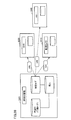
- FIG. 1 is a diagram conceptually illustrating an example of a configuration of an information management system. It is a figure showing the outline
- FIG. 1 is a diagram showing an outline of a configuration of an information management system 10 according to an embodiment of the present invention.
- the information management system 10 includes a mobile communication terminal 100, a regional medical data bank system 120, and a terminal device 133.
- the mobile communication terminal 100 receives positioning signals sent from GPS (Global Positioning System) satellites 160-1 to 160-n (hereinafter collectively referred to as GPS satellites 160), and performs mobile communication based on each positioning signal.
- the position of the terminal 100 can be specified.
- the mobile communication terminal 100 can be connected to the network 150 and can transmit information to other information communication devices via the network 150 or receive information from other information communication devices.
- the mobile communication terminal 100 can be connected to the location information management server 110 or the regional medical data bank system 120 via the Internet.
- the regional medical data bank system 120 includes a server 120A and a server 120B.
- the mobile communication terminal 100 functions as a PHR (Personal Health Record) card.
- the PHR is insurance related information of a patient who is a user of a PHR card.
- PHR includes, for example, height, weight, blood type, vital information, presence / absence of allergies, presence / absence of drug side effects, history, symptoms and prescription, administration, etc., but may also include other information.
- the PHR card is a portable communication device having a position information acquisition function, a communication function, and an information processing function, and may include, for example, a smartphone, an IC (Integrated Circuit) card, a bracelet, and the like.
- the PHR card indicates the patient's own state at the time of the patient's visit or hospitalization, or notifies the attending physician or the diagnostic terminal of the whereabouts or state even when the patient falls down in the hospital or on the street.
- the PHR card can display disaster information and support the user's evacuation guidance.
- the mobile communication terminal 100 periodically generates space-time tags. More specifically, the mobile communication terminal 100 acquires position information and time information indicating when the position information is acquired as a space-time tag. The acquisition timing may be variable depending on the type of service provided to the mobile communication terminal 100.
- the mobile communication terminal 100 receives location information authentication, and transmits a space-time tag including the location information to the regional medical data bank system 120.
- the position information can be used in units of mesh data, which are regional meshes defined as longitude and latitude grids on the map in order to digitize the information on the map or to collect various statistical information. For example, when a specific place is specified by position information, a regional mesh including the position information is specified. Therefore, when it is desired to know a user who has been in the area mesh during a certain period, such a user can be extracted by designating the period and position information.
- the location information management server 110 is connected to the network 150.
- the location information management server 110 is realized by a computer having a known configuration, for example.
- position information management server 110 authenticates whether or not the information representing the position of mobile communication terminal 100 is valid based on a signal sent from mobile communication terminal 100. If the information indicating the position is valid, the position information management server 110 gives an authentication result indicating that the position information of the mobile communication terminal 100 is valid. For example, when the mobile communication terminal 100 and the position information management server 110 have a satellite positioning function, the time of the mobile communication terminal 100 and the time of the position information management server 110 are synchronized with each other. The time information indicating the acquired time is valid time information. Therefore, a set of these position information and time information can constitute a space-time tag.
- the clocks of the devices constituting the information management system 10 are synchronized.
- the timeline of the space-time tag stored in the regional medical data bank system 120 matches the timeline of the space-time tag sent from the mobile communication terminal 100, so that an error in extracting data using the space-time tag is prevented. Can be done.
- Clock synchronization is realized, for example, using time information included in a signal sent from the GPS satellite 160.
- the server 120A and the server 120B are each connected to the network 150.
- the server 120A includes a space-time ID information processing unit 121 and a space-time ID information DB (database) 122.
- the server 120B includes an EHR (Electronic Health Record) information DB 123, a collation (matching) processing unit 124, and a personal health information DB 125.
- the server 120A and the server 120B are each realized by a computer device having a known configuration.
- Server 120A and server 120B are connected by a switch (not shown) when processing by collation (matching) processing unit 124 is performed.
- the switch operation is performed, for example, when an instruction is given to the server 120A and the server 120B, but the trigger of the switch operation is not limited to this.
- the space-time ID information processing unit 121 stores the space-time tag (position information + time information) sent from the mobile communication terminal 100 in the space-time ID information DB 122.
- a folder in which the space-time tag is accumulated is created for each user who uses the service of the regional medical data bank system 120. Therefore, when personal information such as user medical information is required, for example, a plurality of space-time tags stored in the user folder specified by the terminal identification information are searched.
- the EHR information DB 123 holds an electronic health record (EHR).
- the electronic health record includes personal health / medical information sent from the medical institution 130 and other medical institutions.
- the EHR information DB 123 is configured so that health / medical information (for example, electronic medical record) that has been closed for each medical institution can be shared by medical institutions in the region.
- the personal health information DB 125 holds health and medical information (PHR) for the life of each individual unit. Therefore, an institution that requires the health / medical information of the individual can obtain the health / medical information from the personal health information DB 125 when obtaining consent from the individual.
- PHR health and medical information
- a terminal device 133 is connected to the network 150.
- the terminal device 133 is installed in a hospital or other medical institution 130.
- the location information of the medical institution 130 itself can be specified by, for example, an ID assigned by the management authority for each medical institution or other facility.
- the terminal device 133 and the regional medical data bank system 120 are connected by, for example, a dedicated line.
- the medical institution 130 further includes a transmitter 131.
- the transmitter 131 transmits a signal having the same configuration as the positioning signal in a place where the positioning signal transmitted by the GPS satellite 160 does not propagate, for example, indoors or between high-rise buildings.
- the transmitter 131 is realized as, for example, an indoor transmitter called an IMES transmitter (Indoor Messaging System).
- the signal includes information indicating the position of the transmitter 131.
- the information indicating the position is not limited to geographical coordinates such as latitude, longitude, and altitude, but may include a floor ID (Identification), an RF (Radio Frequency) tag, and the like. Further, the geographic coordinates are not limited to the above examples, and may be any coordinate system included in the geographic coordinate system.
- the signal transmitted from one transmitter 131 includes information capable of specifying the position.
- the mobile communication terminal 100 has a position information acquisition function for detecting the signal from the transmitter 131, the mobile communication terminal 100 Even if the signal from the GPS satellite 160 cannot be received, the position of the transmitter 131 can be detected as the position of the mobile communication terminal 100 by receiving the signal from the transmitter 131.
- the terminal device 133 is connected to an NFC terminal 132 having an NFC (Near Field Communication) function.
- the NFC terminal 132 can communicate with the mobile communication terminal 100 and other communication terminals having an NFC function.
- the NFC terminal 132 detects a touch by the mobile communication terminal 100, the terminal identification information of the mobile communication terminal 100 or service identification information for identifying a service provided by the medical institution 130 in which the NFC terminal 132 is installed, Requests to the mobile communication terminal 100.
- the service identification information identifies a service for each medical field that the user receives as a patient in the medical institution 130 (for example, surgery, internal medicine, etc.).
- the mobile communication terminal 100 displays on the monitor of the mobile communication terminal 100 an inquiry as to whether or not to permit transmission of terminal identification information and service identification information to the NFC terminal 132.
- the mobile communication terminal 100 approves touching the monitor to transmit information to the NFC terminal 132
- the mobile communication terminal 100 transmits terminal identification information and service identification information to the NFC terminal 132.
- the NFC terminal 132 transmits the terminal identification information and service identification information received from the mobile communication terminal 100 to the terminal device 133.
- the communication mode with the mobile communication terminal 100 is not limited to the NFC technology, and infrared communication, Bluetooth (registered trademark), or other short-range communication technology may be used.
- the terminal device 133 transmits information acquired by the medical institution 130 to the regional medical data bank system 120 via the network 150.
- the transmitted information 180 includes, for example, a space-time tag 181 and medical information 182.
- the medical information 182 is information representing details of medical practice, prescription, and the like in the medical institution 130, for example. The configuration of the space-time tag 181 will be described later.
- the terminal device 133 When the terminal device 133 is approved by the user of the mobile communication terminal 100, the terminal device 133 transmits the medical action, prescription and other medical information performed at that time to the server 120B. Therefore, the space-time ID and the medical information stored in the EHR information DB 123 can be said to be event-driven data.
- the mobile communication terminal 100 periodically transmits the information 170 to the regional medical data bank system 120. Therefore, the space-time tag stored in the space-time ID information DB 122 and the space-time tag stored in the EHR information DB 123 are not exactly the same.
- the terminal device 133 can communicate with the usage application 140.
- the usage application 140 includes a usage terminal 141.
- the usage terminal 141 has an NFC function, for example.
- the use terminal 141 is realized by a computer having a known configuration, for example.
- the usage application 140 includes entities that use medical information, such as administration, medical institutions, emergency agencies, and care service providers.
- the usage terminal 141 receives personal medical information from the personal health information DB 125 of the regional medical data bank system 120.
- the use terminal 141 of the use application 140 transmits a PHR (Personal Health Record) -ID to the personal health information DB 125 of the regional medical data bank system 120.
- PHR Personal Health Record
- the information 170 transmitted from the mobile communication terminal 100 to the regional medical data bank system 120 includes a space-time tag 171 and a terminal ID 172.
- the space-time tag 171 includes time information obtained at the time of satellite positioning or time information given by the position information management server 110 and position information obtained by positioning using a signal from each GPS satellite 160. Alternatively, it may include position information sent from a transmitter of position information (for example, transmitter 131).
- the terminal ID 172 includes, for example, a terminal identification number included in a SIM (Subscriber Identity Module) card. Therefore, for example, even if user authentication using the space-time tag 171 fails, user identification using a terminal identification number becomes possible.
- SIM Subscriber Identity Module
- FIG. 2 is a diagram showing an outline of the configuration of a system to which the technical idea according to the present invention is applied.
- the regional medical data bank system 120 is connected to the medical institution 130 via a receipt capture system. For example, information acquired at a clinic or hospital is sent to the regional medical data bank system 120 via a receipt capture system.
- the regional medical data bank system 120 holds the data acquired through the receipt capturing system in the EHR information DB 123 and other databases.
- the regional medical data bank system 120 is further connected to the mobile communication terminal 100 via a secure net phone system and other information communication systems.
- the secure network phone system is a form of so-called watching service, and is a service provided to a single-person household by a health care center.
- each resident of a single household has a mobile communication terminal 100.
- the resident operates the mobile communication terminal 100 to transmit the health status to the health management center.
- the health care center detects a resident who has not been contacted, the health care center prompts a report by placing a telephone for confirmation of safety over the mobile communication terminal 100 of the resident or a fixed telephone.
- the mobile communication terminal 100 is, for example, a smartphone that is easy to use for elderly people, but other mobile communication terminals may be used.
- the user of mobile communication terminal 100 is not limited to an elderly person, and may be a user of medical institution 130 (for example, a patient, a caregiver, an assistant, etc.).
- the mobile communication terminal 100 transmits the behavior log indicating the behavior record of the elderly and health data indicating the health status to the regional medical data bank system 120 via the secure network phone system.
- the action log and health data of the elderly are stored in the action log health information DB as information on daily activities (ADL: Activities of Daily Living).
- ADL Activities of Daily Living
- an individual medical DB is held.
- the individual medical DB includes data acquired from the EHR information DB or the behavior log health information DB.
- the mobile communication terminal 100 held by an elderly person outputs a user ID in response to an operation.
- the output user ID is received by, for example, a PC or other information communication terminal owned by a doctor, a rescuer, a monitoring service provider, or the like.
- This information communication terminal makes an inquiry (PHRID) to the regional medical data bank system 120 using the received user ID.
- the regional medical data bank system 120 determines whether the inquiry is a legitimate inquiry, and if it is a legitimate inquiry, reads the information received from the individual medical DB and issues the inquiry. Send to the person.
- FIG. 3 is a diagram showing the configuration of the position information providing system.
- the position information providing system flies at an altitude of about 20,000 meters above the ground, and transmits GPS satellites 160-1, 160-2, 160- that transmit positioning signals (hereinafter referred to as "positioning signals").
- positioning signals 3 and 160-4, and mobile communication terminals 100-1 to 100-4 functioning as devices that provide position information.
- the portable communication terminals 100-1 to 100-4 are collectively referred to as the portable communication terminal 100.
- the mobile communication terminal 100 is a terminal having a satellite positioning function, such as a mobile phone, a smartphone, a mobile navigation system, and other mobile positioning devices.
- the positioning signal is a so-called spread spectrum signal, for example, a GPS signal.
- the positioning signal is not limited to a GPS signal.
- the positioning system will be described using GPS as an example.
- the technical idea related to the position information providing system is based on other satellite positioning systems (for example, Galileo in Europe and the former Soviet Union). It can also be applied to the developed GLONASS (Global Navigation Satellite System).
- the center frequency of the positioning signal is, for example, 1575.42 MHz, but is not limited thereto.
- the spread frequency of the positioning signal is, for example, 1.023 MHz, but is not limited thereto.
- the frequency of the positioning signal is the same as the frequency of the C / A (Coarse and Access) signal in the existing GPS L1 band. Therefore, since an existing positioning signal receiving circuit (for example, a GPS signal receiving circuit) can be used, the mobile communication terminal 100 can receive a positioning signal without adding a new circuit.
- the positioning signal may be modulated by a 1.023 MHz rectangular wave.
- the user receives the positioning signal using a receiver that can receive and process a new GPS signal. it can.
- the frequency of the rectangular wave is not limited to 1.023 MHz.
- the frequency for modulation may be determined by a trade-off with existing C / A signals and / or spectrum separation to avoid interference with other signals.
- the GPS satellite 160-1 is equipped with a transmitter 311 that transmits a positioning signal.
- the GPS satellites 160-2, 160-3, and 160-4 are also equipped with transmitters 312, 313, and 314 having similar functions, respectively.
- the mobile communication terminals 100-2, 100-3, 100-4 having the same functions as the mobile communication terminal 100-1 can be used in medical institutions 130 and other places where radio waves are difficult to reach.
- a transmitter 131 is attached to the ceiling of the first floor of the medical institution 130.
- the mobile communication terminal 100-4 receives the positioning signal transmitted from the transmitter 131.
- transmitters 131 are attached to the ceilings of the second and third floors of the medical institution 130, respectively.
- each transmitter 131 hereinafter referred to as “ground time” and the time of GPS satellites 160-1, 160-3, 160-4, and 160-2 (referred to as “satellite time”). They can be independent of each other and need not be synchronized. Each satellite time is preferably synchronized.
- a spread spectrum signal transmitted as a positioning signal from each transmitter is generated by modulating a navigation message with a pseudo noise code (PRN (Pseudo Random Noise) code).
- the navigation message includes time data, orbit information, almanac, ionospheric correction data, and the like.
- Each transmitter 311 further has data (PRN-ID (Identification)) for identifying the transmitter 311 itself or a GPS satellite on which the transmitter 311 is mounted.
- the mobile communication terminal 100 has data and a code generator for generating each pseudo noise code.
- the mobile communication terminal 100 receives the positioning signal, the mobile communication terminal 100 performs a demodulation process to be described later using a code pattern of a pseudo-noise code assigned to each satellite, and from which satellite the received signal is transmitted. It can be specified.
- the PRN-ID is included in the data, and it is possible to prevent signal acquisition / tracking with an erroneous code pattern that is likely to occur when the reception level is low.
- Each of the transmitters 311, 312, 313, and 314 is an atomic clock, a storage device for storing data, an oscillation circuit, a processing circuit for generating a positioning signal, and a spectrum generated by a signal generated by the processing circuit.
- An encoding circuit for encoding, a transmission antenna, and the like are included.
- the storage device stores an ephemeris, an almanac of each satellite, ionospheric correction data, etc., and a PRN-ID.
- the processing circuit generates a message for transmission using time information from the atomic clock and each data stored in the storage device.
- each of the transmitters 311, 312, 313, and 314 a code pattern of a pseudo-noise code for performing spread spectrum encoding is defined in advance. Each code pattern is different for each transmitter (that is, for each GPS satellite). The encoding circuit spreads the message using such a pseudo-noise code. Each of the transmitters 311, 312, 313, and 314 converts the encoded signal into a high frequency, and transmits the converted signal to outer space via a transmission antenna.
- the transmitters 311, 312, 313, and 314 transmit spread spectrum signals that do not cause harmful interference with other transmitters.
- “not causing harmful interference” can be ensured by an output level limited to such an extent that interference does not occur.
- this signal is transmitted by a carrier wave called L1 band, for example.
- the transmitters 311, 312, 313, and 314 transmit positioning signals having the same frequency according to the spread spectrum communication method. Therefore, even when the positioning signal transmitted from each satellite is received by the mobile communication terminal 100, each positioning signal is received without mutual interference.
- the positioning signal from the terrestrial transmitter signals from a plurality of transmitters can be received without interference from each other, similarly to the signal transmitted from the satellite.
- FIG. 4 is a block diagram illustrating a hardware configuration of the transmitter 131.
- the transmitter 131 includes a digital processing block 410, an EEPROM (Electronically Erasable and Programmable Read Only Memory) 440 electrically connected to the digital processing block 410, and a digital processing block 410.
- UART Universal Asynchronous Receiver Transmitter
- UART Universal Asynchronous Receiver Transmitter
- digital input / output interface 460 electrically connected to the digital processing block 410
- a clock 480 electrically connected to the digital processing block 410.
- the digital processing block 410 includes a CPU (Central Processing Unit) 420 and a RAM (Random Access Memory) 430.
- CPU Central Processing Unit
- RAM Random Access Memory
- EEPROM 440 stores a program executed by CPU 420, data representing a place where transmitter 131 is installed, and the like.
- the program or data is read from the EEPROM 440 and transferred to the RAM 430 when the transmitter 131 is activated.
- the EEPROM 440 can further store data input from the outside of the transmitter 131.
- the storage device for storing the program or data is not limited to the EEPROM 440. Any storage device that can store data in a nonvolatile manner may be used. Further, as will be described later, when external data is input, any storage device capable of writing data may be used. The data structure of the EEPROM 440 will be described later.
- the digital processing block 410 generates data serving as a source of a signal transmitted by the transmitter 131 as a positioning signal.
- the digital processing block 410 sends the generated data as a bit stream to the analog processing block 490.
- the clock 480 supplies the digital processing block 410 with a clock signal that defines the operation of the CPU 420 or a clock signal for generating a carrier wave.
- the digital input / output interface 460 can monitor the internal state of the transmitter (eg, “PLL Cntrl” signal). Alternatively, the digital input / output interface 460 can accept an input of a code pattern of a pseudo-noise code for spreading and modulating a signal transmitted from the transmitter 131 or an input of data defining a transmission output from the outside. it can. Furthermore, the input of other data to be transmitted from the transmitter 131 can also be accepted. The other data is, for example, text data representing a place where the transmitter 131 is installed.
- the code pattern of the pseudo spread code is input to the transmitter 131, the code pattern is written in an area defined in advance in the EEPROM 440. Thereafter, the written PRN-ID is included in a signal for positioning. Other data is also written in an area reserved in advance in the EEPROM 440 according to the type of the data.
- the UART 450 mutually converts serial transfer system data and parallel transfer system data.
- the external clock 270 is used to adjust the operation of the transmitter 131.
- the external clock 270 receives a frequency input from a power line (not shown) and is also used to calibrate a transmission frequency of a signal for positioning.
- the analog processing block 490 modulates a carrier wave of 1.57542 GHz using the bit stream output from the digital processing block 410, generates a transmission signal, and transmits the transmission signal to the antenna 492.
- the signal is transmitted from the antenna 492.
- a signal having the same configuration as the positioning signal is transmitted from the transmitter 131.
- the content of the signal is not exactly the same as the content included in the positioning signal transmitted from the satellite. An example of the configuration of a signal transmitted from the transmitter 131 will be described later.
- the power source 494 supplies power to each unit constituting the transmitter 131.
- the power source 494 may be built in the transmitter 131 as illustrated in FIG. 4 or may be configured to accept supply of power from the outside.
- the CPU 420 is used as the arithmetic processing device for realizing the processing in the digital processing block 410, but other arithmetic processing devices may be used.
- the digital processing block 410 can be realized by, for example, an electric circuit configured to realize each processing instead of the CPU 420.
- the clock signal (Clk) is supplied from the digital processing block 410 to the analog processing block 490, but may be supplied directly from the clock 480 to the analog processing block 490.
- the digital processing block 410 and the analog processing block 490 are shown separately, but physically, they may be mixed on one chip. .
- FIG. 5 is a diagram conceptually showing one mode of data storage in EEPROM 440 included in transmitter 131.
- the EEPROM 440 includes areas 500 to 540 for storing data.
- a transmitter ID is stored as a number for identifying the transmitter.
- the transmitter ID is, for example, a number and / or an alphabetic character or other combination that is written in a memory in a nonvolatile manner when the transmitter is manufactured.
- the PRN-ID of the pseudo spread code assigned to the transmitter is stored in area 510.
- the name of the transmitter is stored in area 520 as text data.
- the code pattern of the pseudo spread code assigned to the transmitter is stored in the area 530.
- the code pattern of the pseudo spread code is selected from a finite number of code patterns assigned in advance for the position information providing system according to the embodiment of the present invention, and the code pattern of the pseudo spread code assigned to each satellite.
- the code pattern is different from the code pattern.
- the code pattern of the pseudo spread code can be changed to another code pattern input via the digital input / output interface 460.
- the code patterns of pseudo-spreading codes assigned for this position information providing system are limited, but the number of transmitters is the size of the installation location of each transmitter or the configuration of the installation location (such as the number of floors of a building) Depending on the number of transmitters, more transmitters than the number of code patterns may be used. Therefore, there can be a plurality of transmitters having the same pseudo-spread code pattern. In this case, the installation location of the transmitter having the same code pattern may be determined in consideration of the signal output. By doing so, it is possible to prevent a plurality of positioning signals using the same pseudo spread code code pattern from being received simultaneously by the same mobile communication terminal.
- the position data for specifying the place where the transmitter 131 is installed is stored in the area 540.
- the position data is represented as a combination of latitude, longitude, and altitude, for example.
- an address, a building name or building ID, a floor number, a floor ID, an RF tag, and the like may be stored in addition to or instead of the position data.
- FIG. 6 is a block diagram showing a configuration of the positioning function of mobile communication terminal 100.
- the mobile communication terminal 100 includes an antenna 602, an RF (Radio Frequency) front circuit 604 electrically connected to the antenna 602, a down converter 606 electrically connected to the RF front circuit 604, and a down converter 606.
- a / D (Analog to Digital) converter 608 electrically connected to the baseband processor 610 electrically connected to the A / D converter 608, and electrically connected to the baseband processor 610
- the memory 620 includes a plurality of areas for storing code patterns of pseudo-noise codes, which are data for identifying each source of positioning signals. As an example, in one aspect, when 48 code patterns are used, memory 620 includes regions 621-1 to 621-48 as shown in FIG. In another aspect, when more code patterns are used, more area is secured in the memory 620. Conversely, fewer code patterns than the number of areas reserved in the memory 620 may be used.
- the code pattern of the pseudo-noise code for the first satellite is stored in the area 621-1. From this, the code pattern is read out, and the cross-correlation process with the received signal is performed, whereby the signal can be tracked and the navigation message included in the signal can be decoded.
- the method of storing and reading the code pattern is exemplarily shown, but a method of generating a code pattern by a code pattern generator is also possible.
- the code pattern generator is realized, for example, by combining two feedback shift registers. It should be noted that the configuration and operation of the code pattern generator can be easily understood by those skilled in the art. Therefore, detailed description thereof will not be repeated here.
- the code pattern of the pseudo-noise code assigned to the transmitter that transmits the positioning signal is stored in areas 621-37 to 621-48.
- the code pattern of the assigned pseudo-noise code for the first transmitter is stored in area 621-37.
- a transmitter having 12 code patterns can be used, but there is no transmitter using the same code pattern in a range that can be received by the same mobile communication terminal.
- Each transmitter may be arranged individually. By doing in this way, it becomes possible to install 12 or more transmitters on the same floor of the medical institution 130, for example.
- the baseband processor 610 performs positioning based on a correlator unit 612 that receives input of a signal output from the A / D converter 608, a control unit 614 that controls the operation of the correlator unit 612, and data output from the control unit 614. And a determination unit 616 for determining a signal transmission source.
- the navigation processor 630 includes an outdoor positioning unit 632 for measuring the position of the mobile communication terminal 100 outdoors based on a signal output from the determination unit 616, and an indoor mobile communication based on data output from the determination unit 616. And an indoor positioning unit 634 for deriving information representing the position of the terminal 100.
- the antenna 602 can receive the positioning signals transmitted from the GPS satellites 160-1, 160-3, and 160-4 and the positioning signals transmitted from the transmitter 131, respectively. Further, when the mobile communication terminal 100 is realized as a mobile phone, the antenna 602 can transmit and receive a signal for a wireless phone or a signal for data communication in addition to the above-described signals.
- the RF front circuit 604 receives a signal received by the antenna 602 and performs noise removal or filter processing for outputting only a signal having a predetermined bandwidth.
- a signal output from the RF front circuit 604 is input to the down converter 606.
- the down converter 606 amplifies the signal output from the RF front circuit 604 and outputs it as an intermediate frequency. This signal is input to the A / D converter 608.
- the A / D converter 608 performs digital conversion processing on the input intermediate frequency signal and converts it into digital data. Digital data is input to the baseband processor 610.
- the correlator unit 612 performs a correlation process between the code pattern read out from the memory 620 by the control unit 614 and the received signal. For example, the correlator unit 612 performs matching between two types of code patterns provided by the control unit 614 having different code phases by 1 bit and digital data transmitted from the A / D converter 608.
- the correlator unit 612 tracks each positioning signal received by the mobile communication terminal 100 using each code pattern, and specifies a code pattern having an arrangement that matches the bit arrangement of the positioning signal. Thereby, since the code pattern of the pseudo noise code is specified, the mobile communication terminal 100 can determine from which satellite the received positioning signal is transmitted or from the transmitter. Further, the mobile communication terminal 100 can perform demodulation and message decoding using the identified code pattern.
- the determination unit 616 makes the above-described determination and sends data corresponding to the determination result to the navigation processor 630.
- the determination unit 616 determines whether or not the PRN-ID included in the received positioning signal is a PRN-ID assigned to a transmitter other than the transmitter mounted on the GPS satellite.
- a spare code for example, 36 pseudo-noise codes are used.
- PRN-01 to PRN-24 are used as numbers for identifying each GPS satellite (PRN-ID)
- PRN-25 to PRN-36 are used as numbers for identifying spare satellites.
- the spare satellite is a satellite that is newly launched in addition to the satellite that was originally launched. That is, such a satellite is launched in preparation for a failure of a GPS satellite or a transmitter mounted on the GPS satellite.
- PRN-ID to PRN-48 are assigned to the transmitters according to the arrangement of the transmitters, for example. Therefore, if a transmission output that does not interfere with a signal transmitted from each transmitter is used, the same PRN-ID may be used for different transmitters. With such an arrangement, more transmitters can be used than the number of PRN-IDs allocated for terrestrial transmitters.
- the determination unit 616 refers to the code pattern 422 of the pseudo-noise code stored in the memory 620, and the code pattern acquired from the received positioning signal matches the code pattern assigned to the transmitter. Judge whether to do. When these code patterns match, the determination unit 616 determines that the positioning signal is transmitted from the transmitter. Otherwise, the determination unit 616 determines that the signal is transmitted from a GPS satellite, and stores in the memory 620 which satellite the acquired code pattern is assigned to. It is determined with reference to the code pattern. Although an example in which a code pattern is used is shown as an aspect of determination, the above determination may be made by comparing other data. For example, a comparison using PRN-ID may be used for the determination.
- the determination unit 616 sends the data acquired from the identified signal to the outdoor positioning unit 632.
- the data obtained from the signal includes a navigation message.
- the determination unit 616 sends data acquired from the signal to the indoor positioning unit 634.
- This data is a coordinate value set in advance as data for specifying the position of the transmitter 131.
- a number that identifies the transmitter may be used.
- the outdoor positioning unit 632 executes processing for calculating the position of the mobile communication terminal 100 based on the data transmitted from the determination unit 616. More specifically, the outdoor positioning unit 632 calculates the propagation time of each signal using data included in signals transmitted from three or more GPS satellites (preferably four or more), and calculates the calculation time. Based on the result, the position of the mobile communication terminal 100 is calculated. This process is executed using a known satellite positioning method. This process can be easily understood by those skilled in the art. Therefore, the details of the description will not be repeated.
- the indoor positioning unit 634 executes a positioning process when the mobile communication terminal 100 exists indoors based on the data output from the determination unit 616.
- the transmitter 131 transmits a positioning signal including data (time data) for specifying a location. Therefore, when the mobile communication terminal 100 receives such a signal, the data included in the signal can be taken out and used as the position of the mobile communication terminal 100.
- the indoor positioning unit 634 performs this process. Data calculated by the outdoor positioning unit 632 or the indoor positioning unit 634 is used for display on the display 640. Specifically, these data are incorporated in the data for displaying the screen, and an image representing the measured position or an image for displaying the place where the transmitter 131 is installed is generated, and the display 640 is displayed. Is displayed.
- FIG. 7 is a block diagram showing a hardware configuration of mobile communication terminal 100 according to the embodiment of the present invention.
- the portable communication terminal 100 includes a CPU 50, a communication device 51, a switch 52, a camera 53, a flash memory 54, a RAM 55, a ROM 56, a memory card driving device 57, a microphone 58, and an audio signal processing circuit 59.
- a positioning signal reception front end unit 68 and a positioning processing unit 69 are provided.
- a memory card 70 can be attached to the memory card driving device 57.
- the antenna 71 receives a signal transmitted from the base station, or transmits a signal for communicating with another communication device via the base station.
- the signal received by the antenna 71 is subjected to front-end processing by the communication device 51, and the processed signal is sent to the CPU 50.
- the switch 52 is realized by a touch panel or a hard switch, and receives an instruction input to the mobile communication terminal 100.
- CPU 50 executes processing for controlling the operation of portable communication terminal 100 based on a command given to portable communication terminal 100.
- the CPU 50 executes a predetermined process based on the signal sent from the communication device 51 and sends the processed signal to the audio signal processing circuit 59.
- the audio signal processing circuit 59 performs predetermined signal processing on the signal and sends the processed signal to the speaker 60.
- the speaker 60 outputs sound based on the signal.
- the microphone 58 receives an utterance to the mobile communication terminal 100 and sends a signal corresponding to the uttered voice to the voice signal processing circuit 59.
- the audio signal processing circuit 59 executes a process specified in advance for a call based on the signal, and sends the processed signal to the CPU 50.
- CPU 50 converts the signal into data for transmission, and sends the converted data to communication device 51.
- the communication device 51 generates a signal for transmission using the data and transmits the signal to the antenna 71.
- the flash memory 54 stores data sent from the CPU 50.
- the CPU 50 reads data stored in the flash memory 54 and executes a predetermined process using the data.
- the RAM 55 temporarily holds data generated by the CPU 50 based on an operation performed on the switch 52.
- the ROM 56 stores a program or data for causing the mobile communication terminal 100 to execute a predetermined operation.
- the CPU 50 reads the program or data from the ROM 56 and controls the operation of the mobile communication terminal 100.
- the memory card driving device 57 reads out data stored in the memory card 70 and sends it to the CPU 50.
- the memory card drive device 57 writes the data output by the CPU 50 in the empty area of the memory card 70.
- the audio signal processing circuit 59 executes signal processing for a call as described above.
- the CPU 50 and the audio signal processing circuit 59 are shown as separate configurations. However, in other aspects, the CPU 50 and the audio signal processing circuit 59 may be configured as an integral unit. Good.
- the display 350 is a touch panel type display, but the mechanism of the touch panel is not particularly limited.
- the display 350 displays an image defined by the data based on the data acquired from the CPU 50. For example, the attributes (still file name, performer, performance time, etc.) of still images, moving images, and music files stored in the flash memory 54 are displayed.
- the LED 62 realizes a predetermined light emission operation based on a signal from the CPU 50.
- the data communication I / F 63 receives attachment of a data communication cable.
- the data communication I / F 63 sends a signal output from the CPU 50 to the cable.
- the data communication I / F 63 sends data received via the cable to the CPU 50.
- the communication I / F 66 communicates with other devices having the NFC communication function using the NFC communication function.
- Vibrator 64 performs an oscillating operation at a predetermined frequency based on a signal output from CPU 50.
- the GPS antenna 602 receives a signal transmitted from a GPS satellite, and sends the received signal to the positioning signal reception front end unit 68.
- the positioning signal reception front end unit 68 performs pattern matching based on each signal received from at least three (preferably four or more) GSP satellites, and the portable communication terminal 100 holds the code pattern included in each signal.
- the signal is sent to the positioning processing unit 69.
- the positioning processing unit 69 performs positioning processing using the signal, and calculates the position of the mobile communication terminal 100 that has received the signal.
- the CPU 50 displays the calculation result on the display 350.
- the secondary battery 65 may include a plurality of battery packs in a certain aspect.
- the main battery pack of the plurality of battery modules may be detachable, and the sub battery pack may be a built-in type. In this way, even when the main battery pack is removed for replacement, the mobile communication terminal 100 can be driven by the power supplied from the sub battery pack.
- FIG. 8 is a block diagram showing a configuration of a computer 800 having a known configuration.
- the location information management server 110, server 120A, server 120B, terminal device 133, usage terminal 141, information processing device 1910, space-time ID management system 1930, information processing terminal 1940, etc. Implemented using a configuration.
- the computer 800 includes, as main components, a CPU 1 that executes a program, a mouse 2 and a keyboard 3 that receive input of instructions from a user of the computer 800, data generated by execution of the program by the CPU 1, Alternatively, a RAM 4 that stores data input via the mouse 2 or the keyboard 3 in a volatile manner, a hard disk 5 that stores data in a nonvolatile manner, an optical disk drive device 6, a communication I / F 7, and a monitor 8 are provided. . Each component is connected to each other by a bus. A CD-ROM 9 and other optical disks are mounted on the optical disk drive 6.
- the communication I / F 7 includes, but is not limited to, a USB (Universal Serial Bus) interface, a wired LAN (Local Area Network), a wireless LAN, and a Bluetooth (registered trademark) interface.
- the processing in the computer 800 is realized by hardware constituting the computer 800 and software executed by the CPU 1.
- Such software may be stored in the hard disk 5 in advance.
- the software is stored in a CD-ROM 9 or other non-volatile computer-readable data recording medium and distributed as a program product.
- the software may be provided as a program product that can be downloaded by an information provider connected to the Internet or other networks.
- Such software is read from the data recording medium by the optical disk driving device 6 or other data reading device, or downloaded via the communication I / F 7 and then temporarily stored in the hard disk 5.
- the software is read from the hard disk 5 by the CPU 1 and stored in the RAM 4 in the form of an executable program.
- the CPU 1 executes the program.
- Each component constituting the computer 800 shown in FIG. 8 is a general one. Therefore, it can be said that the most essential part according to the present embodiment is a program stored in the computer 800. Since the operation of each hardware of computer 800 is well known, detailed description will not be repeated.
- Data recording media are not limited to CD-ROM, FD (Flexible Disk), and hard disk, but are magnetic tape, cassette tape, optical disc (MO (Magnetic Optical Disc) / MD (Mini Disc) / DVD (Digital Versatile Disc)). ), IC (Integrated Circuit) card (including memory card), optical card, mask ROM, EPROM (Electronically Programmable Read-Only Memory), EEPROM, flash ROM, non-volatile that carries a fixed program
- the data recording medium may be used.
- the program here may include not only a program directly executable by the CPU but also a program in a source program format, a compressed program, an encrypted program, and the like.
- FIG. 9 is a diagram showing details of the space-time ID according to the embodiment of the present invention.
- the space-time ID 900 includes space-time tags 910, 920, 930, 940, 950, and the like.
- Each space-time tag includes position information and time information as information elements.
- the position information includes data for representing coordinate values of the space, such as latitude x, longitude y, and altitude z.
- the position information is not limited to position information specified based on signals transmitted from GPS or other positioning satellites.
- the position information may include information specified based on a signal transmitted by the transmitter 131.
- This information is not limited to latitude, longitude, and altitude, but may be indicated by the number of floors of a building, floor ID, RF tag, or the like.
- the time information may include, for example, any one of time data acquired from a positioning signal transmitted by the GPS satellite 160 and time data included in a signal transmitted by the transmitter 131.
- Patient's biological information, medical information, medication information, and other life information are associated with the space-time tag.
- the space-time tag is generated, for example, every certain time (for example, 30 seconds).
- the space-time tag can be generated in response to an operation of the user of mobile communication terminal 100.
- a space-time tag may be generated in response to a generation command sent from a service provider to which the user of mobile communication terminal 100 is subscribed.
- the space-time ID which is a continuous set of information elements without interruption, is an individual action itself. Therefore, a space-time ID that is a set of space-time tags is used for identifying personal information.
- the position of the mobile communication terminal 100 is specified by three-dimensional information (for example, latitude x, longitude y, altitude z), floor ID, RF tag, and other information.
- the mobile communication terminal 100 is outdoors and can receive positioning signals respectively transmitted from at least four GPS satellites 160, the mobile communication terminal 100 is based on the at least four positioning signals. Get location information.
- the mobile communication terminal 100 specifies position information from a pseudo signal transmitted by the transmitter 131 or other transmitter.
- the location of the mobile communication terminal 100 is specified in four dimensions by adding time information (t) to the acquired position information.
- time information t
- the accuracy of time information is maintained using a UTC (Coordinated Universal Time) based time stamp server.
- each combination of time a (t), b (t), c (t), d (t), e (t) and position information at the time is a space-time tag. 910, 920, 930, 940, 950.
- location information is not always constant. For example, Japan's national land is located at multiple plate boundaries, and each plate moves in different directions, causing complex crustal movements. For this reason, the reference point used for surveying also shifts the actual position on the earth and the coordinate value indicated by the survey result over time due to the influence of crustal movement. For example, depending on the location, the surface of the earth is said to have moved about 6 cm in one year. Therefore, in order to maintain the accuracy of the position information (latitude, longitude, altitude) for a long time, the influence of distortion due to crustal movement can be corrected. Therefore, it is desirable to periodically update the map information used in the present embodiment.
- the position information stored in the space-time ID information DB 122 may not match the actual position after several decades. Therefore, in such a case, the version information of the map information when the position information is acquired may be stored in the space-time ID information DB 122 so that the position information can be corrected.
- the position information stored in the space-time ID information DB 122 can be corrected using the map information specified by the version information. It should be noted that crustal deformation that affects the position information and the correction are well known to those skilled in the art. Therefore, a more detailed description will not be given.
- FIG. 10 is a diagram conceptually showing a continuous relationship between position information and time information constituting information elements in the present embodiment.
- the position information 1000 is represented by, for example, latitude, longitude, altitude, and time information. Further, by continuously acquiring the personal position information, it is possible to grasp the trajectory of the individual's action.
- the personal location information constitutes a space-time tag.
- a plurality of space-time tags constitute a space-time ID.
- the user of the mobile communication terminal 100 is present at a point 1010, for example.
- the user's space-time tag 910 includes time information (time a (t)) and position information (latitude x1, longitude y1 and altitude z1 of the point 1010) at time a (t).
- the user of the mobile communication terminal 100 exists at the point 1020.
- the user's space-time tag 920 includes time information (time b (t)) and position information at time b (t) (latitude x2, longitude y2 and altitude z2 of the point 1020).
- the user's travel route from the point 1010 to the point 1020 is a locus 1015.
- the trajectory 1015 corresponds to a space-time ID from time a (t) to time b (t). The accuracy of the trajectory 1015 depends on the frequency of positioning performed between time a (t) and time b (t).
- the timing at which positioning is performed is, for example, when a preset acceleration is detected at a preset time interval, or when the mobile communication terminal 100 receives another signal from the medical institution 130 or other organization. However, positioning may be performed at other timings. The same applies to the following.
- the user exists at the point 1030 at time c (t).
- the user's space-time tag 930 includes time information (time c (t)) and position information (latitude x3, longitude y3, altitude z3 of the point 1030) at time c (t).
- a user's travel route from the points 1010 to 1030 is a locus 1025.
- the locus 1025 corresponds to the space-time ID from time a (t) to time c (t).
- the user exists at the point 1040.
- the user's space-time tag 940 includes time information (time d (t)) and position information at time d (t) (latitude x4, longitude y4, altitude z4 of the point 1040).
- the movement path of the user from the point 1010 to the point 1040 is a locus 1035.
- the trajectory 1035 corresponds to a space-time ID from time a (t) to time d (t).
- the user exists at the point 1050.
- the user's space-time tag 950 includes time information (time e (t)) and position information at time e (t) (latitude x5, longitude y5, altitude z5 of the point 1050).
- a trajectory from the point 1010 to the point 1050 is specified as a trajectory 1045.
- the trajectory 1015 corresponds to the space-time ID from time a (t) to time d (t).
- FIG. 11 is a diagram showing correspondence in which data associated with each service received by the user of mobile communication terminal 100 is linked with a “space-time tag”.
- the user goes to the hospital 1110.
- the hospital 1110 the user receives medical care.
- the patient ID 1111 is associated with the user.
- the medical information 1112 includes examination data 1113, treatment data 1114, and medication data 1115.
- the mobile communication terminal 100 which is a PHR card, acquires location information at regular time intervals and transmits the location information and terminal information to the regional medical data bank system 120.
- Data 1122 representing a service provided by the care facility 1120 includes rehabilitation data 1123 and discourse data 1124.
- the rehabilitation data 1123 includes, for example, the type and contents of rehabilitation performed at the care facility 1120.
- the discourse data 1124 includes, for example, the type, time, content, etc. of the discourse with the care supporter performed at the care facility 1120.
- the watch data 1132 includes video data 1133 and 1134.
- Video data 1133 represents, for example, a video acquired when the user was first captured by sensor / camera 1130.
- Video data 1134 represents video acquired immediately before the user is out of the field of view of sensor / camera 1130.
- An information home appliance 1140 is installed at the user's home.
- Information appliance 1140 is, for example, a self-propelled robot or other device.
- the apparatus includes, for example, a detection function that accepts an operation by a user, a camera that photographs the user, and the like.
- the information home appliance 1140 outputs information 1142 in response to a user operation.
- Information 1142 includes operation data 1143 and 1144.
- the operation data 1143 is data acquired after the user switches on the information home appliance 1140, for example.
- the operation data 1143 includes the type and content of instructions given to the information home appliance 1140.
- the operation data 1143 includes a selected channel. This data is acquired when the user turns off the information appliance 1140.
- the operation data 1144 includes data indicating that the power of the television is turned off.
- the hospital 1110, the care facility 1120, the sensor / camera 1130, and the information home appliance 1140 may be assigned different user IDs. Therefore, in such a case, it is difficult to share user IDs assigned individually.
- an ID studied in medical NDD or the like is an anonymous ID, and an individual cannot be specified. Therefore, information with such an ID cannot be reused in other medical institutions.
- the data formats created in the hospital 1110, the care facility 1120, the sensor / camera 1130, and the information home appliance 1140 are generally different. Therefore, it is not easy to aggregate data of different formats. Therefore, there is a need for a technique that can be reused in other organizations and that facilitates data aggregation.
- the NFC terminal 132 installed in the medical institution 130 or other institution tags the position information and time information.
- the user ID 1111 is associated with the space-time tag 1150.
- the space-time tag 1150 includes time information representing the date and time when the user has accepted and position information representing the place of reception.
- the inspection data 1113 is associated with the space-time tag 1151.
- the space-time tag 1151 includes time information indicating when the examination is performed, and position information for identifying the examination room where the examination is performed or the apparatus used for the examination.
- the treatment data 1114 is associated with the space-time tag 1152.
- the space-time tag 1152 includes time information indicating the time at which the treatment is performed (for example, date / time / minute / second when the completion of the treatment is input to the electronic medical record system) and position information indicating the place where the treatment is performed. .
- the medication data 1115 is associated with the space-time tag 1153.
- the space-time tag 1153 includes time information indicating a time when the medication is performed and position information indicating a place where the medication is performed.
- the position information may include position information obtained using a signal from the GPS satellite 160 and position information received from a device for transmitting the position information, such as the transmitter 131.
- the user ID 1121 is associated with the space-time tag 1154 in the care facility 1120.
- the space-time tag 1154 includes time information indicating the time when the user has accepted (for example, the date, time, minute, and second when the reception is input to the system), and position information indicating the place of reception.
- the rehabilitation data 1123 is associated with the space-time tag 1155.
- the space-time tag 1155 includes time information indicating a time when rehabilitation is performed (for example, date / time / minute / second when an input indicating completion of rehabilitation is performed) and position information indicating a place where the rehabilitation is performed.
- the discourse data 1124 is associated with the space-time tag 1156.
- the space-time tag 1156 includes time information indicating the time when the discourse is performed (for example, the date, time, minute, and second when the input indicating the end of the discourse is input to the respondent's tablet terminal) and the position information indicating the place where the discourse is performed. Including.
- the video data 1133 is associated with the space-time tag 1157.
- the space-time tag 1157 includes time information indicating the time (year / month / day / hour / minute / second) when the video data 1133 was acquired, and position information indicating the location where the video data was acquired.
- Video data 1134 is associated with space-time tag 1158.
- the space-time tag 1158 includes time information indicating the time (year / month / day / hour / minute / second) when the video data 1134 was acquired, and position information indicating the location where the video data was acquired.
- the position information in the space-time tags 1157 and 1158 is based on, for example, data included in a signal transmitted by the transmitter 131 built in the sensor / camera 1130 or the transmitter 131 installed in the vicinity of the sensor / camera 1130. Is.
- the operation data 1143 is associated with the space-time tag 1159.
- the space-time tag 1159 includes time information indicating the time (year / month / day / hour / minute / second) when the information home appliance 1140 is operated, and position information indicating the place where the information home appliance 1140 is operated.
- the operation data 1144 is associated with the space-time tag 1160.
- the space-time tag 1160 includes time information indicating the time (year / month / day / hour / minute / second) when the information home appliance 1140 is operated, and position information indicating the place where the information home appliance 1140 is operated.
- the location information included in the space-time tags 1159 and 1160 is based on a signal transmitted from the transmitter 131 disposed at the user's home. Accordingly, the position information can be acquired by the transmitter 131 even indoors where a positioning signal transmitted by the GPS 160 is not received.
- a space-time ID 1100 is generated.
- the space-time ID 1100 is composed of a plurality of space-time tags along the timeline.
- the mobile communication terminal 100 or the regional medical data bank system 120 Based on the data authenticated by the location information management server 110, the mobile communication terminal 100 or the regional medical data bank system 120 generates the data. More specifically, the space-time ID 1100 includes space-time tags 1170 to 1180.
- the space-time tag 1170 is associated with the user ID 1111 and the contents of the space-time tag 1150.
- the space-time tag 1171 is associated with the inspection data 1113 and the contents of the space-time tag 1151.
- the space-time tag 1172 is associated with the treatment data 1114 and the contents of the space-time tag 1152.
- the space-time tag 1173 is associated with the medication data 1115 and the contents of the space-time tag 1153.
- the space-time tag 1174 is associated with the user ID 1121 and the contents of the space-time tag 1154.
- the space-time tag 1175 is associated with the rehabilitation data 1123 and the contents of the space-time tags 1153 and 1155.
- the space-time tag 1176 is associated with the discourse data 1124 and the contents of the space-time tag 1156.
- the space-time tag 1177 is associated with the video data 1133 and the contents of the space-time tag 1157.
- the space-time tag 1178 is associated with the video data 1134 and the contents of the space-time tag 1158.
- the space-time tag 1179 is associated with the operation data 1143 and the contents of the space-time tag 1159.
- the space-time tag 1180 is associated with the operation data 1144 and the contents of the space-time tag 1160.
- the collation processing unit 124 stores the trajectory information including the position information stored in the space-time information DB 122, the space-time tag 181 and the medical information 182 stored in the EHR information DB 123.
- the collation processing unit 124 collates position information and time information associated with each of a series of space-time tags constituting the space-time ID with the space-time tag 181 transmitted from the medical institution 130. If the space-time tag 181 is included in the series of space-time tags, it can be understood that the medical information 182 is medical information about the user of the mobile communication terminal 100 that generated the space-time tag 181.
- FIG. 12 is a diagram illustrating an example of a system configuration using the regional medical data bank system 120.
- the regional medical data bank system 120 is connected to the terminal device 133 via the network 150.
- the regional medical data bank system 120 can communicate with the mobile communication terminal 100 via the network 151.
- a transmitter 131 is attached to the ceiling of the examination room.
- the NFC terminal 132 is connected to the terminal device 133.
- the user for example, Mr. A
- the transmitter 131 arranged in the examination room of the medical institution 130 transmits a signal including position information.
- the position information includes, for example, latitude, longitude, altitude or floor level, and a secure code.
- the secure code is a code assigned in advance to the transmitter 131 in order to indicate that the signal itself is valid.
- the mobile communication terminal 100 receives a signal transmitted by the transmitter 131 and acquires position information included in the signal.
- the position information acquired at this time is stored in the memory of the mobile communication terminal 100 as the IMES indoor position 1240, for example.
- the mobile communication terminal 100 receives the positioning signal transmitted by the GPS 160. For example, the mobile communication terminal 100 acquires a position based on each positioning signal transmitted from four GPS satellites 160. The position acquired at this time is stored in the memory of the mobile communication terminal 100 as the GNSS outdoor position 1250, for example. Similarly, the position is acquired every preset time while the user walks outside. The acquired position is held in the memory as, for example, GNSS outdoor positions 1251, 1252, and 1253.
- the mobile communication terminal 100 receives the location information (latitude, longitude, altitude or floor number) received at the location, the secure code, and the mobile communication terminal 100. Is transmitted to the terminal device 133.
- the terminal device 133 generates a space-time ID based on the position information received from the mobile communication terminal 100.
- the terminal device 133 further adds the space-time ID to the medical information.
- the terminal device 133 transmits medical information to which the space-time ID is added to the regional medical data bank system 120.
- FIG. 13 is a diagram showing a position mode in which a space-time ID is generated and used.
- the IMES registration system installer 1310 distributes position information (latitude, longitude, altitude, etc.) and a secure code to a mesh data GIS (Geographic Information System) server 1340.
- the mesh data GIS server 1340 is configured to provide geographic information.
- the IMES registration system installer 1310 transmits the location information and temporary PRN (no application) to the management organization 1320.
- the management organization 1320 is an organization involved in the operation of an organization that transmits a positioning signal, for example.
- the management organization 1320 transmits position information (latitude L, longitude I, altitude H) and PRN (determined) to the IMES registration system installer 1310.
- IMES registration system installer 1310 transmits the location information and temporary PRN (with application) to supervisory organization 1330 via management organization 1320.
- the management organization 1320 will apply for the location information code to the supervisory organization 1330.
- the supervisory organization 1330 distributes the applied location information code to the IMES registration system installer 1310.
- the supervisory organization 1330 is, for example, the Geographical Survey Institute.
- the IMES registration system installer 1310 transmits position information (L, I, H, MID, floor number) to the transmitter 131, and the transmitter 131 defines the received data in advance. Write to memory area.
- the IMES registration system installer 1310 transmits position information (L, I, H, MID, floor number) to the authentication server 1350.
- the authentication server 1350 holds the data as IMES-master information.
- the transmitter 131 transmits a signal including a position within a predetermined range (for example, a radius of 1 m, 2 m, etc.).
- the signal is defined by type 1, MID (binary), for example, as IMES transmission data. When the mobile communication terminal 100 is within the range, such a signal is received and position information is acquired.
- the mobile communication terminal 100 transmits location information and a terminal ID to the location information management server 110 as an IMES log.
- the location information management server 110 executes an authentication process 159 using the IMES log sent from the mobile communication terminal 100 and the data stored in the authentication server 1350.
- the result of the authentication is associated with a time stamp output by the time stamp server 1360. Further, the result of the authentication is also transmitted to the regional medical data bank system 120.
- the mobile communication terminal 100 transmits the position information (latitude, longitude, altitude) and the terminal ID to the position information management server 110 as a GNSS log.
- the timing of transmission is not particularly limited.
- the location information management server 110 associates the reception time output from the time stamp server 1360 with the GNSS log, and transmits the associated data to the regional medical data bank system 120.
- the data is stored in the space-time ID information DB 122 as a space-time tag (GNSS).
- the space-time tag is stored in a file created for each user. Each file includes terminal identification information, a user name, a space-time tag (position information + time information), a version number of map data when the position information is acquired, and the like.
- a series of space-time tags may constitute a space-time ID.
- the processing by the matching processing unit 124 is applied to the space-time ID information DB 122 and the EHR information DB 123.
- the result of the processing by the matching processing unit 124 is stored in the personal health information DB 125.
- data stored in the personal health information DB 125 is used as appropriate by the usage application 140.
- the usage application 140 can be used, for example, by a health insurance institution or other provider of medical services.
- the mobile communication terminal 100 transmits the position information (IMES position) to the terminal device 133 via the NFC terminal 132.
- the NFC terminal 132 transmits data obtained by adding an NFC-ID to the signal received from the mobile communication terminal 100 to the terminal device 133.
- the terminal device 133 has a medical information log function, and can sequentially record the medical information of each patient.
- the terminal device 133 transmits the space-time ID (L, I, H, MID, PRN, floor number) and shared information (for example, diagnostic information) to the EHR information DB 123 of the regional medical data bank system 120.
- the EHR information DB 123 holds the information.
- FIG. 14 is a diagram conceptually showing one mode of data storage in personal health information DB 125 according to the embodiment of the present invention.
- the personal health information DB 125 stores a plurality of space-time tags.
- One space-time tag 1400 is associated with medical information 1410, care information 1420, and sensor information 1430, respectively. Therefore, when the space-time tag 1400 is specified, the medical information 1410, the care information 1420, and the sensor information 1430 are specified.
- FIG. 15 is a flowchart showing the action log registration process.
- FIG. 16 is a flowchart showing a medical information registration process.
- FIG. 17 is a flowchart showing a process for using personal health information.
- step S1510 CPU 50 of user portable communication terminal 100 counts time. For example, the time is counted based on a signal from a clock provided in the mobile communication terminal 100.
- step S1515 CPU 50 determines whether or not a predetermined time has elapsed from the start of counting. When CPU 50 determines that a predetermined time has elapsed (YES in step S1515), CPU 50 switches control to step S1520. If not (NO in step S1515), CPU 50 returns control to step S1510.
- step S1520 CPU 50 obtains position information.
- step S1525 CPU 50 makes an inquiry to position information management server 110.
- step S1530 the CPU 1 of the location information management server 110 receives location information from the mobile communication terminal 100.
- step S1535 CPU 1 determines whether or not the received signal is an IMES signal. This determination is made based on an item (for example, PRN-ID) included in the signal received from mobile communication terminal 100. If CPU 1 determines that the received signal is an IMES signal (YES in step S1535), CPU 1 switches control to step S1540. If not (NO in step S1535), CPU 1 switches control to step S1545.
- an item for example, PRN-ID
- step S1540 CPU 1 determines whether or not the position information included in the signal received from mobile communication terminal 100 is valid position information. When CPU 1 determines that the position information is valid position information (YES in step S1540), CPU 1 switches control to step S1545. If not (NO in step S1540), CPU 1 switches control to step S1550. In step S1545, CPU 1 adds a time stamp to the position information. In step S1545, CPU 1 returns the space-time tag having the position information and time information and the authentication result to portable communication terminal 100.
- step S1560 CPU 50 of mobile communication terminal 100 receives the space-time tag and the authentication result from position information management server 110.
- CPU 50 determines whether or not the acquired position information is valid position information. For example, if CPU 50 determines that the position information is valid position information (YES in step S1565), CPU 50 switches control to step S1570. If not (NO in step S1565), the control returns to step S1510.
- step S 1570 CPU 50 transmits the space-time tag and the terminal ID of portable communication terminal 100 to regional medical data bank system 120.
- CPU 1 of regional medical data bank system 120 stores the space-time tag and terminal ID received from portable communication terminal 100 in space-time ID information DB 122.
- the data storage format is not particularly limited.
- the configuration of the database may be at least a multi-dimensional database model format such as a cache.
- step S1610 CPU 50 of mobile communication terminal 100 determines whether or not a predetermined time has elapsed.
- CPU 50 determines that a predetermined time has elapsed (YES in step S1615)
- CPU 50 switches control to step S620. If not (NO in step S1615), CPU 50 returns control to step S1610.
- step S1620 CPU 50 obtains position information.
- step S1625 CPU 50 makes an inquiry to position information management server 110.
- step S1630 the CPU 1 of the location information management server 110 receives the location information transmitted from the mobile communication terminal 100.
- step S1635 CPU 1 determines whether or not the signal is an IMES signal. This determination is made based on the items included in the IMES signal, similarly to the above determination.
- CPU 1 determines that the signal is an IMES signal (YES in step S1635)
- CPU 1 switches control to step S1640. If not (NO in step S1635), CPU 1 switches control to step S1645.
- step S1640 CPU 1 determines whether or not the information included in the signal is valid position information.
- CPU 1 determines that the information is valid position information (YES in step S 1640)
- CPU 1 switches control to step S 1645. If not (NO in step S1640), CPU 1 switches control to step S1650.
- step S1645 CPU 1 adds a time stamp (time information) to the position information.
- step S1650 CPU 1 returns a space-time tag having position information and time information and an authentication result to portable communication terminal 100.
- step S1655 CPU 50 of mobile communication terminal 100 receives the space-time tag and authentication result transmitted from position information management server 110.
- CPU 50 determines whether the position information is valid position information. When CPU 50 determines that the position information is valid position information (YES in step S1660), CPU 50 switches control to step S1665. If not (NO in step S1660), CPU 50 returns control to step S1610.
- step S ⁇ b> 1665 CPU 50 transmits the latest space-time tag to terminal device 133 in response to being touched by NFC.
- step S1670 the CPU 1 of the terminal device 133 receives the space-time tag from the mobile communication terminal 100 via NFC.
- step S1675 CPU 1 generates a data set in which a space-time tag is added to medical information (for example, examination results, vital data, etc.).
- step S1680 CPU 1 transmits medical information with a space-time tag added to regional medical data bank system 120.
- step S1585 in the regional medical data bank system 120, the CPU 1 of the server 120B stores the information received from the terminal device 133 in the EHR information DB 123.
- step S1690 CPU 1 collates the space-time tag stored in space-time ID information DB 122 with the space-time tag stored in EHR information DB. If the collation result is OK, in step S1695, CPU 1 registers the space-time tag in personal health information DB 125. If the collation result is NG, the CPU 1 can notify the terminal device 133 that the space-time tag cannot be registered.
- step S1710 CPU 50 of mobile communication terminal 100 transmits the user ID and authentication information of mobile communication terminal 100 to terminal device 133 in response to touching NFC terminal 132.
- step S1720 the CPU 1 of the terminal device 133 receives the user ID and authentication information transmitted from the mobile communication terminal 100 via the NFC terminal 132.
- step S1725 CPU 1 creates inquiry information using the user ID and authentication information.
- step S ⁇ b> 1730 CPU 1 of terminal device 133 transmits inquiry information to regional medical data bank system 120.
- step S1740 in the regional medical data bank system 120, the CPU 1 of the server 120B receives the inquiry information sent from the terminal device 133.
- step S1745 CPU 1 determines whether or not the inquiry information is a valid inquiry. When CPU 1 determines that the inquiry information indicates a valid inquiry (YES in step S1745), CPU 1 switches control to step S1750. If not (NO in step S1745), CPU 1 switches control to step S1770.
- step S1750 server 120B transmits a connection request to server 120A.
- the server 120A switches the switch in response to the connection request and establishes a connection between the server 120A and the server 120B.
- the CPU 1 reads the space-time ID composed of a series of space-time tags stored in the space-time ID information DB 122 and the personal health information corresponding to the inquiry information from the personal health information DB 125.
- step S1755 CPU 1 of server 120B transmits the read personal health information to terminal device 133.
- step S1760 the CPU 1 of the terminal device 133 receives the personal health information transmitted from the regional medical data bank system 120.
- CPU 1 of terminal device 133 causes monitor 8 to display personal health information.
- step S1770 CPU 1 of server 120B returns a reply indicating that inquiry is impossible to terminal device 133.
- personal medical information and other service information can also be acquired by the use terminal 141.
- the use terminal 141 has the NFC function
- the user ID and the space-time tag are received from the mobile communication terminal 100 in response to the touch of the mobile communication terminal 100.
- the usage terminal 141 transmits the PHR-ID associated with the user ID to the server 120B and requests personal medical information.
- the server 120B compares the received PHR-ID with the PHR-ID stored in the regional medical data bank system 120, and determines whether or not the request is a valid request. If the request is a valid request, the server 120B transmits a connection request to the server 120A.
- the verification processing unit 124 checks whether or not the space-time tag transmitted from the use terminal 141 to the server 120B is included in the series of space-time tags stored in the space-time ID information DB 122 of the server 120A.
- the server 120B reads the health information associated with the space-time tag from the personal health information DB 125 and transmits the health information to the user terminal 141.
- action logs and medical information are registered in the regional medical data bank system 120, and personal health information is used.
- personal health information is used.
- the server 120A and the server 120B are connected when there is a legitimate request, leakage of information stored in the personal health information DB 125 is prevented.
- FIG. 18 is a diagram illustrating an example of a space-time tag 181 in a certain situation.
- the space-time tag 181 includes a time stamp 1810, a latitude 1820, a longitude 1830, a URI 1840 (Uniform Resource Identifier), and a MIME 1850 (Multipurpose Internet Mail Extensions).
- the time stamp 1810 corresponds to time information obtained by satellite positioning or time information obtained by a time stamp server that authenticates the validity of position information.
- Latitude 1820, longitude 1830, and altitude 1835 correspond to position information obtained by satellite positioning or position information obtained by the transmitter 131.
- the URI 1840 is information for accessing, for example, information provided by an organization in which the space-time tag 181 is generated.
- MIME 1850 is data associated with the space-time tag 181 and corresponds to character information, a still image, a moving image, and the like.
- FIG. 19 is a diagram conceptually illustrating an example of the configuration of the information management system.
- the information management system includes an information processing device 1910, an EHR information DB 1920, a space-time ID management system 1930, and an information processing terminal 1940.
- the space-time ID management system 1930 includes a service interface 1931, a space-time tag DB 1932, a space-time ID 1933, and a personal information DB 1934.
- the information processing device 1910 is, for example, an electronic medical record system or other device, and outputs information (for example, test results or other EHR data) unique to each user (for example, a patient) who receives medical services or other services. (Step S1).
- the EHR information DB 1920 takes in the EHR data and associates the time information and the position information with the EHR data to generate a space-time tag.
- the information processing device 1910 transmits the space-time tag to the space-time ID management system 1930 (step S2).
- the space-time ID management system 1930 takes in each space-time tag via the service interface 1931 and stores it in the space-time tag DB 1932.
- the space-time ID DB 1933 reads a series of space-time tags from the space-time tag DB 1932.
- the space-time ID DB 1933 forms personal identification information with the series of space-time tags as space-time IDs.
- the personal information DB 1934 holds medical information, care information and other information (PHR) provided to individuals.
- the information processing terminal 1940 executes the application and requests the space-time ID management system 1930 to request personal information (step S4).
- the space-time ID management system 1930 matches the space-time tag included in the request sent from the information processing terminal 1940 with the space-time tag constituting the space-time ID stored in the space-time tag DB 1932. Then, it is determined whether or not the request for personal information is valid (step S3).
- the space-time ID management system 1930 determines that the personal information request is valid as a result of the matching process
- the space-time ID management system 1930 reads the data referenced by the URI included in the space-time tag constituting the space-time ID from the EHR information DB 1920, Further, PHR is read from the personal information DB 1934.
- the service I / F 1931 transmits the read data or PHR to the information processing terminal 1940 (step S5).
- FIG. 20 is a diagram illustrating an outline of the configuration of the information management system.
- the information management system includes a monitoring camera system 2010 in addition to the configuration shown in FIG.
- the surveillance camera system 2010 includes a camera and a memory for holding an image.
- the surveillance camera system 2010 can be connected to the Internet and other networks.
- a URI is assigned to the monitoring camera system 2010.
- the space-time ID management system 1930 may receive a URI associated with the space-time tag sent from the surveillance camera system 2010. Therefore, the space-time ID management system 1930 can access the image acquired by the monitoring camera system 2010 with reference to the URI.
- the image is associated with the space-time data, and is not associated with personal information such as a name, for example. Therefore, personal information is not specified from the image.
- the patient side holds the smartphone mobile terminal, records (logs) location information at regular intervals, and transmits the location information to the regional medical data bank system 120.
- the provider side of medical services / services receives information (medical information) necessary for medical analysis from the billing data (receipt information) used for medical claims for each act for which NFC has obtained direct consent from the patient.
- the location information of the place for example, the medical institution 130
- the time information that is, space-time ID
- medical information for each patient can be aggregated by matching (collating) both space-time IDs.
- the space-time ID is not only used for PCs used in medical institutions, but also for medical information or health information from terminals used by providers such as nursing care services and insurance services, TVs, cameras, cleaning robots, and other information appliances. Easy to add. As a result, it is possible to provide a new mechanism for information sharing in the medical industry and other industries that must share information over a wide range.
Landscapes
- Engineering & Computer Science (AREA)
- Theoretical Computer Science (AREA)
- Databases & Information Systems (AREA)
- Health & Medical Sciences (AREA)
- Physics & Mathematics (AREA)
- General Physics & Mathematics (AREA)
- Data Mining & Analysis (AREA)
- General Engineering & Computer Science (AREA)
- Biomedical Technology (AREA)
- Business, Economics & Management (AREA)
- General Health & Medical Sciences (AREA)
- Primary Health Care (AREA)
- General Business, Economics & Management (AREA)
- Signal Processing (AREA)
- Computer Networks & Wireless Communication (AREA)
- Remote Sensing (AREA)
- Epidemiology (AREA)
- Public Health (AREA)
- Medical Informatics (AREA)
- Tourism & Hospitality (AREA)
- Telephonic Communication Services (AREA)
- Mobile Radio Communication Systems (AREA)
- Management, Administration, Business Operations System, And Electronic Commerce (AREA)
- Medical Treatment And Welfare Office Work (AREA)
- Child & Adolescent Psychology (AREA)
- Economics (AREA)
- Human Resources & Organizations (AREA)
- Marketing (AREA)
- Strategic Management (AREA)
Abstract
情報管理システム(10)は、位置情報を取得可能な携帯通信端末(100)と、地域医療データバンクシステム(120)、送信機(131)が設けられた医療機関(130)とを備える。携帯通信端末(100)は、時間情報および位置情報からなる時空タグと端末IDとを地域医療データバンクシステム(120)に送信する。地域医療データバンクシステム(120)の時空ID情報処理部(121)は、ユーザ毎のフォルダに、複数の時空タグから時空IDを生成し、時空ID情報DB(122)に格納する。医療機関(130)の端末装置(133)は、携帯通信端末(100)の位置情報と時間情報とを地域医療データバンクシステム(120)に送信する。照合処理部(124)は、携帯通信端末(100)からの情報と、利用端末(141)からの情報とを照合し、情報の送信要求が正当な場合に、利用端末(141)に当該情報を送信する。
Description
本開示は情報の管理に関し、より特定的には、位置情報と時間情報とを用いて情報を管理する技術に関する。
従来、個人が保持する携帯通信端末の位置情報を、時間の経過とともに収集する技術が知られている。たとえば、特開2008-072205号公報(特許文献1)は、「個人の行動を正確に特定する」ための技術を開示している(要約参照)。特開2005-063372号公報(特許文献2)は、「情報を保管できる形式に変換する作業を人手によらず連続的に実施し大量に生成された変換後の情報をすべて参照可能な形で電子的に自動的に蓄積することが可能で、かつプライバシー保護が可能な個人行動記録蓄積技術」を開示している(要約参照)。特開2010-282401号公報(特許文献3)は、「利用者のプライバシーを適切に保護しつつ、位置情報管理サーバにおける処理負荷の集中を防止し、サービス提供者が柔軟に利用者端末の位置情報を取得する」ための技術を開示している(要約参照)。
ところで、個人にサービスが提供される業界のうち、たとえば、医療業界においては、各医療機関が診療情報やサービス情報を共有し、診察その他の医療サービスの効率化や患者の利便性の向上を目指す要望が強い。しかし、現在のところ、医療情報やサービス情報は、医療機関毎や介護サービス機関毎に付与された患者の識別コード(ID:Identification)で運用されている。さらに、モニタその他の様々なセンサーから出力されるセンサー情報は、当該センサーが属するシステム毎に付与された個別の装置識別コードで運用される場合がある。そのため、様々な患者の識別コードや装置識別コードが関連付けられた医療情報やサービス情報を共通化することは困難である。
また、医療情報だけを共有するための共通の識別コード等も検討されている。医療情報には、たとえば、個人の健康状態を表わす健康データも含まれ得る。健康データは、特に高齢者の健康データのように、医療機関のみでなく、介護、保険その他の周辺サービスにも利用可能であるため、その他のサービスが利用できることが望ましい。また、情報通信ネットワークの発展に伴い、各種のモニター、センサーその他の情報取得装置から得られる情報も必要に応じて共有できることが望ましい。したがって、識別情報その他の様々な情報を効率的にまたは管理するための技術が必要とされている。また、個人の行動を認証するための技術が必要とされている。
本開示は上述のような背景を考慮してなされたものであって、ある局面における目的は、情報を共有することができる情報管理システムを提供することである。他の局面における目的は、個人の行動を識別することができる情報管理システムを提供することである。他の局面における目的は、共有可能な情報を生成する携帯通信端末を提供することである。他の局面における目的は、個人の行動を認証することができる情報を生成できる携帯通信端末を提供することである。他の局面における目的は、個人の情報を共有可能なデータバンク装置を提供することである。他の局面における目的は、共有可能なサービス情報を管理するためのサービス情報管理装置を提供することである。
他の局面における目的は、ユーザデータの管理方法を提供することである。他の局面における目的は、共有可能なユーザデータを生成するように携帯通信端末を制御するための方法を提供することである。他の局面における目的は、共有可能なユーザデータを管理するデータベースの制御方法を提供することである。他の局面における目的は、共有可能なユーザに提供されるサービス情報を管理するサービス情報管理装置の制御方法を提供することである。
さらに他の局面における目的は、上記のいずれかの方法をコンピュータに実行させるためのプログラムを提供することである。
一実施の形態に従う情報管理システムは、各々が位置情報を取得可能な複数の携帯通信端末と、複数の携帯通信端末の各ユーザのデータベースを管理するためのデータバンク装置と、複数の携帯通信端末のうちの特定の携帯通信端末のユーザに提供されるサービスに関連付けられるサービス情報をデータバンク装置に送信するためのサービス情報管理装置とを備える。携帯通信端末は、当該携帯通信端末の位置を特定するための位置情報と時間情報との組を含む識別情報を取得するように構成された取得部と、複数の識別情報をデータバンク装置およびサービス情報管理装置に送信するように構成された第1の送信部とを備える。サービス情報管理装置は、特定の携帯通信端末から識別情報を受信するように構成された受信部と、サービス情報と、特定の携帯通信端末から受信した識別情報とを、データバンク装置に送信するように構成された第2の送信部とを備える。データバンク装置は、複数の携帯通信端末の各々によって送信された識別情報と、サービス情報管理装置によって送信された識別情報およびサービス情報とを受信するように構成された受信部と、サービス情報が関連付けられたサービスを提供されたユーザを特定するために、受信された各識別情報を照合するように構成された照合部とを備える。
好ましくは、携帯通信端末において、取得部は、複数の測位衛星からそれぞれ送信される各測位信号に基づいて、携帯通信端末の位置情報と時刻とを取得するように構成された第1測位部と、各複数の測位衛星から送信される測位信号と同じ形式の信号を送信可能な位置情報送信装置から、当該位置情報送信装置の位置を表わす位置情報を含む信号を受信し、当該受信した信号から位置情報を抽出し、当該位置情報に関連付けられる時刻を取得するように構成された第2測位部とを含む。
好ましくは、第2測位部は、第2測位部によって抽出された位置情報に関連付けられる時刻を、位置情報送信装置以外から取得するように構成されている。
好ましくは、情報管理システムは、各携帯通信端末によって取得された識別情報を認証するための認証装置をさらに備える。認証装置は、各携帯通信端末から、第2測位部によって抽出された位置情報を受信するように構成された受信部と、受信された位置情報が正当な位置情報であるか否かを確認するように構成された判断部と、受信された位置情報が正当な位置情報である場合に、各携帯通信端末から受信した位置情報に時間情報を付与して、当該位置情報を送信した携帯通信端末に返信するように構成された時刻付与部とを含む。
好ましくは、第1の送信部は、携帯通信端末のユーザによる承認に基づいて、識別情報をサービス情報管理装置に送信する。
好ましくは、取得部は、予め設定された間隔で複数の位置情報を取得する。
好ましくは、当該携帯通信端末が予め登録された範囲に存在している場合に、取得部は、位置情報を取得する。
好ましくは、当該携帯通信端末が予め登録された範囲に存在している場合に、取得部は、位置情報を取得する。
他の実施の形態に従うと、携帯通信端末が提供される。この携帯通信端末は、当該携帯通信端末の位置を特定するための位置情報と時間情報との組を含む識別情報を取得するように構成された取得部と、複数の識別情報を、当該携帯通信端末のユーザのデータベースを管理するためのデータバンク装置と、当該ユーザに提供されるサービスに関連付けられるサービス情報をデータバンク装置に送信するサービス情報管理装置とに送信するように構成された送信部とを備える。
好ましくは、取得部は、複数の測位衛星からそれぞれ送信される各測位信号に基づいて、携帯通信端末の位置情報と時刻とを取得するように構成された第1測位部と、各複数の測位衛星から送信される測位信号と同じ形式の信号を送信可能な位置情報送信装置から、当該位置情報送信装置の位置を表わす位置情報を含む信号を受信し、当該受信した信号から位置情報を抽出し、当該位置情報に関連付けられる時刻を取得するように構成された第2測位部とを含む。
好ましくは、送信部は、携帯通信端末のユーザによる承認に基づいて、識別情報をサービス情報管理装置に送信する。
好ましくは、取得部は、予め設定された間隔で複数の位置情報を取得する。
好ましくは、携帯通信端末が予め登録された範囲に存在している場合に、取得部は、位置情報を取得する。
好ましくは、携帯通信端末が予め登録された範囲に存在している場合に、取得部は、位置情報を取得する。
他の実施の形態に従うと、複数の携帯通信端末の各ユーザのデータベースを管理するためのデータバンク装置が提供される。データバンク装置は、複数の携帯通信端末の各々から、当該携帯通信端末の位置を特定するための位置情報と時間情報との組を含む識別情報を受信し、複数の携帯通信端末のうちの特定の携帯通信端末のユーザに提供されるサービスに関連付けられるサービス情報をデータバンク装置に送信するためのサービス情報管理装置から識別情報を受信するように構成された受信部と、サービス情報が関連付けられたサービスを提供されたユーザを特定するために、受信された各識別情報を照合するように構成された照合部とを備える。
他の実施の形態に従うと、サービス情報管理装置が提供される。このサービス情報管理装置は、位置情報を取得可能な携帯通信端末から、位置情報と時間情報との組を含む識別情報を受信するように構成された受信部と、携帯通信端末のユーザに提供されるサービスに関連付けられるサービス情報を、携帯通信端末のユーザのデータベースを管理するためのデータバンク装置に送信するように構成された送信部とを備える。
他の実施の形態に従うと、位置情報を認証するための認証装置が提供される。認証装置は、複数の測位衛星から送信される測位信号と同じ形式の信号を送信可能な位置情報送信装置によって送信された位置情報を受信するように構成された受信部と、位置情報が正当であるか否かを確認するように構成された確認部と、位置情報が正当である場合に、位置情報が正当であることを示す情報を付与して位置情報送信装置に送信するように構成された送信部とを備える。
好ましくは、位置情報が正当であることを示す情報は、時間情報を含む。
他の実施の形態に従うと、データの管理方法が提供される。この管理方法は、位置情報を取得可能な複数の携帯通信端末の各々について、当該携帯通信端末の位置を特定するための位置情報と時間情報との組を含む識別情報を取得するステップと、識別情報を、複数の携帯通信端末の各ユーザのデータベースを管理するためのデータバンク装置と、複数の携帯通信端末の各ユーザに提供されるサービスに関連付けられるサービス情報をデータバンク装置に送信するためのサービス情報管理装置と、に送信するステップと、各携帯通信端末の識別情報を受信するステップと、複数の携帯通信端末のうちの特定の携帯通信端末のユーザに提供されたサービスに関連付けられるサービス情報と、複数の携帯通信端末の各々から受信した識別情報とを、データバンク装置に送信するステップと、特定の携帯通信端末によって送信された識別情報を受信するステップと、特定の携帯通信端末から受信した識別情報と、サービス情報管理装置によって送信された識別情報とを比較するステップとを含む。
他の実施の形態に従うと、データの管理方法が提供される。この管理方法は、位置情報を取得可能な複数の携帯通信端末の各々について、当該携帯通信端末の位置を特定するための位置情報と時間情報との組を含む識別情報を取得するステップと、識別情報を、複数の携帯通信端末の各ユーザのデータベースを管理するためのデータバンク装置と、複数の携帯通信端末の各ユーザに提供されるサービスに関連付けられるサービス情報をデータバンク装置に送信するためのサービス情報管理装置と、に送信するステップと、各携帯通信端末の識別情報を受信するステップと、複数の携帯通信端末のうちの特定の携帯通信端末のユーザに提供されたサービスに関連付けられるサービス情報と、複数の携帯通信端末の各々から受信した識別情報とを、データバンク装置に送信するステップと、特定の携帯通信端末によって送信された識別情報を受信するステップと、特定の携帯通信端末から受信した識別情報と、サービス情報管理装置によって送信された識別情報とを比較するステップとを含む。
他の実施の形態に従うと、携帯通信端末の制御方法が提供される。この方法は、当該携帯通信端末の位置を特定するための位置情報と時間情報との組を含む識別情報を取得するステップと、識別情報を、当該携帯通信端末のユーザのデータベースを管理するためのデータバンク装置および当該ユーザに提供されるサービスに関連付けられるサービス情報をデータバンク装置に送信するサービス情報管理装置に送信するステップとを含む。
他の実施の形態に従うと、複数の携帯通信端末の各ユーザのデータベースを管理するための方法が提供される。この方法は、複数の携帯通信端末の各々から、当該携帯通信端末の位置を特定するための位置情報と時間情報との組を含む識別情報を受信し、複数の携帯通信端末のうちの特定の携帯通信端末のユーザに提供されるサービスに関連付けられるサービス情報をデータバンク装置に送信するためのサービス情報管理装置から識別情報を受信するステップと、サービス情報が関連付けられたサービスを提供されたユーザを特定するために、受信された各識別情報を照合するステップとを含む。
他の実施の形態に従うと、サービス情報の管理方法が提供される。この方法は、位置情報を取得可能な携帯通信端末から、当該携帯通信端末の位置情報と時間情報との組を含む識別情報を受信するステップと、携帯通信端末のユーザに提供されるサービスに関連付けられるサービス情報を、携帯通信端末のユーザのデータベースを管理するためのデータバンク装置に送信するステップとを含む。
他の実施の形態に従うと、上記のいずれかに記載の方法をコンピュータに実行させるためのプログラムが提供される。
この発明の上記および他の目的、特徴、局面および利点は、添付の図面と関連して理解されるこの発明に関する次の詳細な説明から明らかとなるであろう。
以下、図面を参照しつつ、本発明の実施の形態について説明する。以下の説明では、同一の部品には同一の符号を付してある。それらの名称および機能も同じである。したがって、それらについての詳細な説明は繰り返さない。
[情報管理システムの構成]
図1を参照して、本実施の形態に係る情報管理システム10について説明する。図1は、本発明の実施の形態に係る情報管理システム10の構成の概要を表わす図である。ある局面において、情報管理システム10は、携帯通信端末100と、地域医療データバンクシステム120と、端末装置133とを備える。
図1を参照して、本実施の形態に係る情報管理システム10について説明する。図1は、本発明の実施の形態に係る情報管理システム10の構成の概要を表わす図である。ある局面において、情報管理システム10は、携帯通信端末100と、地域医療データバンクシステム120と、端末装置133とを備える。
携帯通信端末100は、GPS(Global Positioning System)衛星160-1から160-n(以下総称するときは、GPS衛星160という。)から送られる測位信号を受信し、各測位信号に基づいて携帯通信端末100の位置を特定することができる。また、携帯通信端末100は、ネットワーク150に接続可能であり、ネットワーク150を介して他の情報通信装置に情報を送信し、あるいは、他の情報通信装置から情報を受信できる。たとえば、携帯通信端末100は、インターネットを介して、位置情報管理サーバ110または地域医療データバンクシステム120に接続することができる。地域医療データバンクシステム120は、サーバ120Aと、サーバ120Bとを含む。
ある局面において、携帯通信端末100は、PHR(Personal Health Record)カードとして機能する。本実施の形態において、PHRとは、PHRカードのユーザである患者の保険関連情報である。PHRは、たとえば、身長、体重、血液型、バイタル情報、アレルギーの有無、医薬の副作用の有無、既往歴、症状および処方、投与等を含むが、その他の情報も含み得る。本実施の形態において、PHRカードは、位置情報取得機能と通信機能と情報処理機能とを有する携帯可能な通信機器であり、たとえば、スマートフォン、IC(Integrated Circuit)カード、腕輪等を含み得る。PHRカードは、患者の通院時や入院時に患者自身の状態を示したり、病院内や路上で倒れた場合でも居場所や状態を主治医または診断用端末に通知する。また、PHRカードのユーザがいる地域が災害に遭遇した場合には、PHRカードは、災害情報を表示して、ユーザの避難誘導を支援し得る。
携帯通信端末100は、定期的に時空タグを生成する。より具体的には、携帯通信端末100は、位置情報と、当該位置情報が取得された時を示す時間情報とを、時空タグとして取得する。取得のタイミングは、携帯通信端末100に提供されるサービスの種類に応じて可変であってもよい。携帯通信端末100は、位置情報管理サーバ110において、位置情報の認証を受け、認証を受けた位置情報を含む時空タグを、地域医療データバンクシステム120に送信する。
なお、位置情報は、たとえば、地図上の情報をデジタル化したり各種統計情報をとるために地図上の経緯度方眼として定められた地域メッシュであるメッシュデータ単位で利用可能である。たとえば、特定の場所が位置情報で特定されると、当該位置情報を含む地域メッシュが特定される。したがって、ある期間に当該地域メッシュにいたユーザを知りたい場合、その期間と位置情報とを指定することにより、そのようなユーザを抽出できる。
ネットワーク150には、位置情報管理サーバ110が接続されている。位置情報管理サーバ110は、たとえば周知の構成を有するコンピュータによって実現される。ある局面において、位置情報管理サーバ110は、携帯通信端末100から送られた信号に基づいて、携帯通信端末100の位置を表わす情報が正当なものであるか否かを認証する。当該位置を表す情報が正当なものである場合には、位置情報管理サーバ110は、携帯通信端末100の位置情報が正当であることを示す認証結果を付与する。たとえば、携帯通信端末100と位置情報管理サーバ110とが衛星測位機能を有する場合には、携帯通信端末100の時刻と位置情報管理サーバ110の時刻とは同期しているので、正当な位置情報が取得された時を示す時間情報は、正当な時間情報となる。したがって、これらの位置情報と時間情報との組は、時空タグを構成し得る。
ある局面において、情報管理システム10を構成する各装置のクロックは、それぞれ同期していることが好ましい。この場合、地域医療データバンクシステム120に蓄積される時空タグのタイムラインと、携帯通信端末100から送られる時空タグのタイムラインとが一致するので、時空タグを用いたデータの抽出の誤りが防止され得る。クロックの同期は、たとえば、GPS衛星160から送られる信号に含まれる時刻情報を用いて実現される。
地域医療データバンクシステム120において、サーバ120Aとサーバ120Bは、それぞれ、ネットワーク150に接続されている。サーバ120Aは、時空ID情報処理部121と、時空ID情報DB(データベース)122とを備える。サーバ120Bは、EHR(Electronic Health Record)情報DB123と、照合(突合)処理部124と、個人健康情報DB125とを備える。サーバ120Aとサーバ120Bとは、それぞれ、周知の構成を有するコンピュータ装置によって実現される。サーバ120Aとサーバ120Bとは、照合(突合)処理部124による処理が行なわれる時に、スイッチ(図示しない)によって接続される。当該スイッチの動作は、たとえば、サーバ120Aとサーバ120Bに対する命令が与えられた場合に行なわれるが、スイッチの動作のトリガーはこれに限られない。
時空ID情報処理部121は、携帯通信端末100から送られた時空タグ(位置情報+時間情報)を時空ID情報DB122に蓄積する。時空タグが蓄積されるフォルダは、地域医療データバンクシステム120のサービスを利用するユーザごとに作成される。したがって、ユーザの医療情報のような個人情報が必要な場合には、たとえば、端末識別情報によって特定されるユーザのフォルダ内に保存されている複数の時空タグが検索対象となる。
EHR情報DB123は、電子健康記録(EHR:Electronic Health Record)を保持している。電子健康記録は、医療機関130その他の医療機関から送られる個人の健康・医療情報等を含む。EHR情報DB123は、医療機関ごとに閉じていた健康・医療情報(たとえば、電子カルテ)を、地域内の医療機関等で共有できるように構成されている。
個人健康情報DB125は、個人単位の生涯にわたる健康・医療情報(PHR)を保持している。したがって、当該個人の健康・医療情報を必要とする機関は、当該個人から承諾を得た場合に、個人健康情報DB125から健康・医療情報を取得できる。
ネットワーク150には、端末装置133が接続されている。端末装置133は、病院その他の医療機関130に設置されている。医療機関130自体の位置情報は、たとえば、医療機関その他の施設ごとに、管理当局によって割り当てられるIDによって特定され得る。端末装置133と地域医療データバンクシステム120とは、たとえば専用回線で接続されている。医療機関130は、さらに、送信機131を備える。送信機131は、GPS衛星160によって発信される測位信号が伝播しない場所、たとえば、屋内や高層ビルの間等において、測位信号と同様の構成を有する信号を送信する。ある局面において、送信機131は、たとえば、IMES送信機(Indoor Messaging System)とも呼ばれる屋内送信機として実現される。当該信号は、送信機131の位置を表わす情報を含む。なお、位置を表す情報は、緯度、経度、標高のような地理座標に限られず、フロアID(Identification)、RF(Radio Frequency)タグなども含み得る。また、地理座標は上記の例示に限られず、地理座標系に含まれるいずれの座標系によるものでもよい。
一つの送信機131から発信される信号は、位置を特定可能な情報を含む。送信機131から発信される信号が測位信号の構成と同じであり、携帯通信端末100が送信機131からの信号を検出するための位置情報取得機能を有する場合には、携帯通信端末100は、GPS衛星160からの信号を受信できなくても、送信機131からの信号を受信することにより、送信機131の位置を携帯通信端末100の位置として検出することができる。
端末装置133には、NFC(Near Field Communication)機能を有するNFC端末132が接続されている。NFC端末132は、携帯通信端末100その他のNFC機能を有する通信端末と通信可能である。NFC端末132は、携帯通信端末100によるタッチを検出すると、携帯通信端末100の端末識別情報やNFC端末132が設置されている医療機関130によって提供されるサービスを識別するためのサービス識別情報を、携帯通信端末100に要求する。サービス識別情報は、医療機関130においてユーザが患者として受けている医療分野ごとに(たとえば、外科、内科等のように)サービスを識別する。携帯通信端末100は、その要求に応答して、端末識別情報やサービス識別情報をNFC端末132に送信することを許可するか否かを問い合わせる画面を携帯通信端末100のモニタに表示する。携帯通信端末100のユーザが、モニタにタッチして情報をNFC端末132に送信することを承認すると、携帯通信端末100は、端末識別情報やサービス識別情報をNFC端末132に送信する。NFC端末132は、携帯通信端末100から受信した端末識別情報やサービス識別情報を端末装置133に送信する。なお、携帯通信端末100との通信形態は、NFC技術に限られず、赤外線通信、Bluetooth(登録商標)その他の近距離通信技術が用いられてもよい。
端末装置133は、医療機関130において取得された情報を、ネットワーク150を介して地域医療データバンクシステム120に送信する。送信される情報180は、たとえば、時空タグ181と、医療情報182とを含む。医療情報182は、たとえば、医療機関130における医療行為の詳細、処方その他を表す情報である。時空タグ181の構成は後述する。
端末装置133は、携帯通信端末100のユーザによる承認が得られると、その時に行なわれた医療行為や処方その他の医療情報をサーバ120Bに送信する。したがって、EHR情報DB123に保存されている時空IDと医療情報とは、イベントドリブンで発生するデータといえる。一方、携帯通信端末100は、情報170を定期的に地域医療データバンクシステム120に送信する。したがって、時空ID情報DB122に保存されている時空タグと、EHR情報DB123に保存されている時空タグとは全く同じではない。
ある局面において、端末装置133は、利用アプリケーション140と通信可能である。利用アプリケーション140は、利用端末141を含む。利用端末141は、たとえば、NFC機能を有する。利用端末141は、たとえば、周知の構成を有するコンピュータによって実現される。利用アプリケーション140は、医療情報を利用する主体、たとえば、行政、医療機関、救急機関、介護サービス事業者等を含む。
利用アプリケーション140において、利用端末141は、地域医療データバンクシステム120の個人健康情報DB125から個人の医療情報を受信する。また、別の局面において、利用アプリケーション140の利用端末141は、地域医療データバンクシステム120の個人健康情報DB125に対して、PHR(Personal Health Record)-IDを送信する。
携帯通信端末100から地域医療データバンクシステム120に送信される情報170は、時空タグ171と、端末ID172とを含む。ある局面において、時空タグ171は、衛星測位の際に得られた時間情報あるいは位置情報管理サーバ110によって付与された時間情報と、各GPS衛星160からの信号を用いた測位によって得られた位置情報あるいは位置情報の送信機(たとえば送信機131)から送られた位置情報とを含み得る。端末ID172は、たとえば、SIM(Subscriber Identity Module)カードに含まれる端末識別番号を含む。したがって、たとえば、仮に、時空タグ171を用いたユーザ認証が失敗しても、端末識別番号を用いたユーザ識別が可能になる。
[技術思想]
図2を参照して、本実施の形態に係る技術思想についてさらに説明する。図2は、本発明に係る技術思想が適用されるシステムの構成の概略を表わす図である。ある局面において、地域医療データバンクシステム120は、レセプト取込システムを介して医療機関130に接続されている。たとえば、診療所または病院において取得された情報は、レセプト取込システムを介して地域医療データバンクシステム120に送られる。地域医療データバンクシステム120は、レセプト取込システムを介して取得したデータをEHR情報DB123その他のデータベースに保持する。
図2を参照して、本実施の形態に係る技術思想についてさらに説明する。図2は、本発明に係る技術思想が適用されるシステムの構成の概略を表わす図である。ある局面において、地域医療データバンクシステム120は、レセプト取込システムを介して医療機関130に接続されている。たとえば、診療所または病院において取得された情報は、レセプト取込システムを介して地域医療データバンクシステム120に送られる。地域医療データバンクシステム120は、レセプト取込システムを介して取得したデータをEHR情報DB123その他のデータベースに保持する。
地域医療データバンクシステム120は、さらに、安心ネットフォンシステムその他の情報通信システムを介して携帯通信端末100に接続される。本実施の形態において、安心ネットフォンシステムは、所謂見守りサービスの一形態であり、健康管理センターが独居世帯に提供するサービスである。たとえば、独居世帯の住人は、それぞれ携帯通信端末100を有している。住人は、携帯通信端末100を操作して、健康管理センターに健康状態を送信する。健康管理センターは連絡を受けていない住人を検知すると、安否確認のための電話を当該住人の携帯通信端末100あるいは固定電話にかけて報告を促す。携帯通信端末100は、たとえば、高齢者にも使い勝手のよいスマートフォンであるが、その他の携帯通信端末が用いられてもよい。また、本実施の形態において、携帯通信端末100のユーザは、高齢者に限られず、医療機関130のユーザ(たとえば、患者、介護者、補助者等)であればよい。
携帯通信端末100は、高齢者の行動の記録を表わす行動ログや健康状態を示す健康データを安心ネットフォンシステムを介して地域医療データバンクシステム120に送信する。地域医療データバンクシステム120において、高齢者の行動ログや健康データは、日常生活動作(ADL:Activities of Daily Living)の情報として、行動ログ健康情報DBに保存される。地域医療データバンクシステム120において、個人別の医療DBが保持されている。個人別の医療DBは、EHR情報DBもしくはまたは行動ログ健康情報DBから取得されたデータを含む。
ある局面において、高齢者によって保有されている携帯通信端末100は、操作に応答して、ユーザIDを出力する。出力されたユーザIDは、たとえば医師、救護者、見守りサービスの提供者などが所有するPCその他の情報通信端末に受信される。この情報通信端末は、受信したユーザIDを用いて地域医療データバンクシステム120に問い合わせ(PHRID)を行なう。地域医療データバンクシステム120は、その問い合わせが正当な問い合わせであるか否かを判断し、正当な問い合わせである場合には、個人別の医療DBから問い合わせを受けた情報を読み出し、その問い合わせの発行者に送信する。
[位置情報提供システム]
ここで、図3を参照して、本発明の実施の形態において位置情報を提供する仕組みの一態様である位置情報提供システムについて説明する。図3は、位置情報提供システムの構成を表わす図である。位置情報提供システムは、地上の上空約2万メートルの高度を飛行し、測位のための信号(以下、「測位信号」と表わす。)を発信するGPS衛星160-1,160-2,160-3,160-4と、位置情報を提供する装置として機能する携帯通信端末100-1~100-4とを備える。携帯通信端末100-1~100-4を総称するときは、携帯通信端末100と表わす。携帯通信端末100は、たとえば、携帯電話、スマートフォン、携帯ナビゲーションシステムその他の移動体測位装置のように、衛星測位機能を有する端末である。
ここで、図3を参照して、本発明の実施の形態において位置情報を提供する仕組みの一態様である位置情報提供システムについて説明する。図3は、位置情報提供システムの構成を表わす図である。位置情報提供システムは、地上の上空約2万メートルの高度を飛行し、測位のための信号(以下、「測位信号」と表わす。)を発信するGPS衛星160-1,160-2,160-3,160-4と、位置情報を提供する装置として機能する携帯通信端末100-1~100-4とを備える。携帯通信端末100-1~100-4を総称するときは、携帯通信端末100と表わす。携帯通信端末100は、たとえば、携帯電話、スマートフォン、携帯ナビゲーションシステムその他の移動体測位装置のように、衛星測位機能を有する端末である。
測位信号は、いわゆるスペクトラム拡散された信号であり、たとえば、GPS信号である。しかしながら、測位信号はGPS信号に限られない。なお、以下では説明を簡単にするために、測位のシステムをGPSを一例として説明するが、当該位置情報提供システムに係る技術思想は、他の衛星測位システム(たとえば、欧州のGalileo、旧ソ連によって開発されたGLONASS(Global Navigation Satellite System)等)にも適用可能である。
測位信号の中心周波数は、たとえば、1575.42MHzであるが、これらに限られない。測位信号の拡散周波数は、たとえば1.023MHzであるが、これに限られない。この場合、測位信号の周波数は、既存のGPSのL1帯におけるC/A(Coarse and Access)信号の周波数と同一となる。したがって、既存の測位信号受信回路(たとえばGPS信号受信回路)が流用できるため、携帯通信端末100は、新たな回路を追加することなく、測位信号を受信することができる。
測位信号は、1.023MHzの矩形波によって変調されていてもよい。この場合、たとえば、L1帯において新たな送信が計画される測位信号のデータチャネルと同一であれば、利用者は、新しいGPSの信号を受信、処理可能な受信機を用いて当該測位信号を受信できる。なお、矩形波の周波数は、1.023MHzに限られない。変調のための周波数は、既存のC/A信号、および/または、他の信号との干渉を回避するためのスペクトラム分離とのトレードオフによって定められ得る。
GPS衛星160-1には、測位信号を発信する送信機311が搭載されている。GPS衛星160-2,160-3,160-4にも、同様の機能を備える送信機312,313,314がそれぞれ搭載されている。携帯通信端末100-1と同様の機能を有する携帯通信端末100-2,100-3,100-4は、医療機関130その他の電波が届きにくい場所でも使用可能である。医療機関130は、医療機関130の1階の天井には、送信機131が取り付けられている。携帯通信端末100-4は、送信機131から発信される測位信号を受信する。同様に、医療機関130の2階および3階の各フロアの天井にも、送信機131がそれぞれ取り付けられている。ここで、各送信機131の時刻(以下、「地上時刻」という。)と、GPS衛星160-1,160-3,160-4,160-2の時刻(「衛星時刻」という。)とは、互いに独立したものでよく、同期している必要はない。各衛星時刻は、それぞれ同期していることが好ましい。
各送信機から測位信号として発信されるスペクトラム拡散信号は、擬似雑音符号(PRN(Pseudo Random Noise)コード)によって航法メッセージを変調することにより生成される。航法メッセージは、時刻データ、軌道情報、アルマナック、電離層補正データ等を含む。各送信機311は、さらに、それぞれ、当該送信機311自身、あるいは送信機311が搭載されるGPS衛星を識別するためのデータ(PRN-ID(Identification))を有している。
携帯通信端末100は、各擬似雑音符号を発生するためのデータおよびコード発生器を有している。携帯通信端末100は、測位信号を受信すると、各衛星ごとに割り当てられた擬似雑音符号の符号パターンを用いて、後述する復調処理を実行し、受信された信号がどの衛星から発信されたものであるかを特定することができる。また、新しいGPS信号では、データの中にPRN-IDが含まれており、受信レベルが低い場合に生じやすい誤った符号パターンでの信号の捕捉・追尾を防ぐことができる。
GPS衛星に搭載される送信機の構成の概略は、以下のとおりである。送信機311,312,313,314は、それぞれ、原子時計と、データを格納する記憶装置と、発振回路と、測位信号を生成するための処理回路と、処理回路によって生成された信号をスペクトラム拡散符号化するための符号化回路と、送信アンテナ等を有する。記憶装置は、エフェメリス、各衛星のアルマナック、電離層補正データ等を有する航法メッセージと、PRN-IDとを格納している。処理回路は、原子時計からの時間情報と、記憶装置に格納されている各データとを用いて送信用のメッセージを生成する。
送信機311,312,313,314の各々において、スペクトラム拡散符号化するための擬似雑音符号の符号パターンが予め規定されている。各符号パターンは、送信機ごと(すなわちGPS衛星ごと)に異なる。符号化回路は、そのような擬似雑音符号を用いて、上記メッセージをスペクトラム拡散する。送信機311,312,313,314は、それぞれ、符号化された信号を高周波数に変換して、送信アンテナを介して、宇宙空間に発信する。
上述のように、送信機311,312,313,314は、他の送信機との間で有害な干渉を及ぼさないスペクトラム拡散信号を発信する。ここで、「有害な干渉をおこさない」ことは、干渉が生じない程度に制限された出力レベルによって担保され得る。あるいは、スペクトラムを分離する態様によっても実現できる。この信号は、たとえばL1帯と称される搬送波によって送信されている。送信機311,312,313,314は、たとえば、同一の周波数を有する測位信号を拡散スペクトル通信方式にしたがって発信する。したがって、各衛星から送信された測位信号が携帯通信端末100に受信される場合にも、各々の測位信号は、互いに混信を受けることなく受信されることになる。地上の送信機からの測位信号についても、衛星から送信された信号と同様に、複数の送信機からの信号は、互いに混信を受けることなく受信されることができる。
[IMES送信機]
図4を参照して、送信機131について説明する。図4は、送信機131のハードウェア構成を示すブロック図である。図4に示されるように、送信機131は、デジタル処理ブロック410と、デジタル処理ブロック410に電気的に接続されているEEPROM(Electronically Erasable and Programmable Read Only Memory)440と、デジタル処理ブロック410に電気的に接続されているUART(Universal Asynchronous Receiver Transmitter)450と、デジタル処理ブロック410に電気的に接続されているデジタル入出力インターフェイス460と、デジタル処理ブロック410に電気的に接続されているクロック480と、デジタル処理ブロック410に電気的に接続されているアナログ処理ブロック490と、アナログ処理ブロック490に電気的に接続されているアンテナ492と、電源494とを備える。デジタル処理ブロック410は、CPU(Central Processing Unit)420と、RAM(Random Access Memory)430とを含む。
図4を参照して、送信機131について説明する。図4は、送信機131のハードウェア構成を示すブロック図である。図4に示されるように、送信機131は、デジタル処理ブロック410と、デジタル処理ブロック410に電気的に接続されているEEPROM(Electronically Erasable and Programmable Read Only Memory)440と、デジタル処理ブロック410に電気的に接続されているUART(Universal Asynchronous Receiver Transmitter)450と、デジタル処理ブロック410に電気的に接続されているデジタル入出力インターフェイス460と、デジタル処理ブロック410に電気的に接続されているクロック480と、デジタル処理ブロック410に電気的に接続されているアナログ処理ブロック490と、アナログ処理ブロック490に電気的に接続されているアンテナ492と、電源494とを備える。デジタル処理ブロック410は、CPU(Central Processing Unit)420と、RAM(Random Access Memory)430とを含む。
EEPROM440は、CPU420が実行するプログラム、送信機131が設置されている場所を表わすデータ等を格納する。当該プログラムあるいはデータは、送信機131が起動する時に、EEPROM440から読み出され、RAM430に転送される。EEPROM440は、また送信機131の外部から入力されたデータをさらに格納することができる。なお、プログラムあるいはデータを格納するための記憶装置は、EEPROM440に限られない。少なくとも、データを不揮発的に保存できる記憶装置であればよい。また、後述するように、外部からのデータが入力される場合には、データを書き込むことができる記憶装置であればよい。EEPROM440のデータ構造については後述する。
デジタル処理ブロック410は、測位のための信号として送信機131によって送信される信号の源泉となるデータを生成する。デジタル処理ブロック410は、アナログ処理ブロック490に対して、生成したデータをビットストリームとして送出する。クロック480は、CPU420の動作を規定するクロック信号、あるいは搬送波を生成するためのクロック信号を、デジタル処理ブロック410に供給する。
デジタル入出力インターフェイス460は、送信機の内部状態(たとえば、「PLL Cntrl」信号)を監視することができる。あるいは、デジタル入出力インターフェイス460は、送信機131から発信される信号を拡散変調するための擬似雑音符号の符号パターンの入力を、あるいは、送信出力を規定するデータの入力を、外部から受け付けることができる。さらに、送信機131から発信されるべき他のデータの入力も受け付けることができる。当該他のデータは、たとえば、送信機131が設置されている場所を表わすテキストデータである。
擬似拡散符号の符号パターンは、送信機131に入力されると、EEPROM440において予め規定された領域に書き込まれる。その後は、その書き込まれたPRN-IDが、測位のための信号に含められる。その他のデータも、EEPROM440において、そのデータの種類に応じて予め確保された領域に書き込まれる。
UART450は、シリアル転送方式のデータとパラレル転送方式のデータを相互に変換する。外部クロック270は、送信機131の動作を調整するために使用される。たとえば、外部クロック270は、電力線(図示しない)から周波数の入力を受け付け、測位のための信号の送信周波数を較正するためにも使用される。
アナログ処理ブロック490は、デジタル処理ブロック410から出力されたビットストリームを用いて、1.57542GHzの搬送波を変調して送信信号を生成し、アンテナ492に送出する。その信号は、アンテナ492より発信される。このようにして、測位のための信号と同様の構成を有する信号が、送信機131から発信される。この場合、信号の内容は、衛星から発信された測位信号に含まれる内容とは、全く同一ではない。送信機131から発信される信号の構成の一例は、後述する。
電源494は、送信機131を構成する各部に電力を供給する。なお、電源494は、図4に示されるように、送信機131に内蔵されてもよいし、外部からの電力の供給を受け付ける態様であってもよい。
以上の説明においては、デジタル処理ブロック410における処理を実現するための演算処理装置としてCPU420が用いられたが、その他の演算処理装置が使用されたもよい。また、送信機131が実現する動作は複雑ではないため、デジタル処理ブロック410は、CPU420に代えて、たとえば、各処理を実現するように構成された電気回路によっても実現できる。また、図4においては、クロック信号(Clk)がデジタル処理ブロック410からアナログ処理ブロック490に供給されているが、クロック480からアナログ処理ブロック490に直接に供給されてもよい。さらに、説明を明確にするために、本実施の形態においては、デジタル処理ブロック410とアナログ処理ブロック490とが別個に示されているが、物理的には、1つのチップに混載されてもよい。
[データ構造]
図5を参照して、送信機131のデータ構造について説明する。図5は、送信機131が備えるEEPROM440におけるデータの格納の一態様を概念的に表わす図である。EEPROM440は、データを格納するための領域500~540を含む。領域500には、送信機を識別するための番号として、送信機IDが格納されている。送信機IDは、たとえば当該送信機の製造時にメモリに不揮発的に書き込まれる数字および/または英文字その他の組み合わせである。当該送信機に割り当てられた擬似拡散符号のPRN-IDは、領域510に格納されている。送信機の名称は、テキストデータとして、領域520に格納されている。
図5を参照して、送信機131のデータ構造について説明する。図5は、送信機131が備えるEEPROM440におけるデータの格納の一態様を概念的に表わす図である。EEPROM440は、データを格納するための領域500~540を含む。領域500には、送信機を識別するための番号として、送信機IDが格納されている。送信機IDは、たとえば当該送信機の製造時にメモリに不揮発的に書き込まれる数字および/または英文字その他の組み合わせである。当該送信機に割り当てられた擬似拡散符号のPRN-IDは、領域510に格納されている。送信機の名称は、テキストデータとして、領域520に格納されている。
当該送信機に割り当てられた擬似拡散符号の符号パターンは、領域530に格納されている。擬似拡散符号の符号パターンは、本発明の実施の形態に係る位置情報提供システム用に予め割り当てられた有限個の複数の符号パターンから選択されたものであり、衛星ごとに割り当てられる擬似拡散符号の符号パターンとは異なる符号パターンである。また、前述のように、擬似拡散符号の符号パターンは、デジタル入出力インターフェイス460を介して入力される他の符号パターンに変更可能である。
本位置情報提供システム用に割り当てられる擬似拡散符号の符号パターンは、有限個であるが、送信機の数は、各送信機の設置場所の広さ、あるいは設置場所の構成(ビルの階数等)に応じて異なり、符号パターンの数よりも多い複数の送信機が使用される場合もある。したがって、同一の擬似拡散符号の符号パターンを有する複数の送信機が存在し得る。この場合は、同一の符号パターンを有する送信機の設置場所を、信号の出力を考慮して決定すればよい。そうすることにより、同一の擬似拡散符号の符号パターンを用いる複数の測位信号が同一の携帯通信端末によって同時期に受信されることは、防止し得る。
送信機131が設置されている場所を特定するための位置データは、領域540に格納されている。位置データは、たとえば、緯度、経度、標高の組み合わせとして表わされる。領域540において、当該位置データに加えて、もしくはデータに代えて、住所、建物の名称もしくは建物ID、階数、フロアID、RFタグ等などが格納されてもよい。
[携帯通信端末の構成]
図6を参照して、携帯通信端末100の構成について説明する。図6は、携帯通信端末100の測位機能の一構成を表わすブロック図である。携帯通信端末100は、アンテナ602と、アンテナ602に電気的に接続されているRF(Radio Frequency)フロント回路604と、RFフロント回路604に電気的に接続されているダウンコンバータ606と、ダウンコンバータ606に電気的に接続されているA/D(Analog to Digital)コンバータ608と、A/Dコンバータ608に電気的に接続されているベースバンドプロセッサ610と、ベースバンドプロセッサ610に電気的に接続されているメモリ620と、ベースバンドプロセッサ610に電気的に接続されているナビゲーションプロセッサ630と、ナビゲーションプロセッサ630に電気的に接続されているディスプレイ640とを備える。
図6を参照して、携帯通信端末100の構成について説明する。図6は、携帯通信端末100の測位機能の一構成を表わすブロック図である。携帯通信端末100は、アンテナ602と、アンテナ602に電気的に接続されているRF(Radio Frequency)フロント回路604と、RFフロント回路604に電気的に接続されているダウンコンバータ606と、ダウンコンバータ606に電気的に接続されているA/D(Analog to Digital)コンバータ608と、A/Dコンバータ608に電気的に接続されているベースバンドプロセッサ610と、ベースバンドプロセッサ610に電気的に接続されているメモリ620と、ベースバンドプロセッサ610に電気的に接続されているナビゲーションプロセッサ630と、ナビゲーションプロセッサ630に電気的に接続されているディスプレイ640とを備える。
メモリ620は、測位信号の各発信源を識別するためのデータである、擬似雑音符号の符号パターンを格納する複数の領域を含む。一例として、ある局面において、48個の符号パターンが用いられる場合には、メモリ620は、図6に示されるように、領域621-1~621-48を含む。また、他の局面において、それ以上の符号パターンが使用される場合には、さらに多くの領域がメモリ620に確保される。逆に、メモリ620に確保された領域の数よりも少ない符号パターンが使用される場合もあり得る。
一例として48個の符号パターンが用いられる場合において、たとえば、24個の衛星が衛星測位システムに用いられる場合、各衛星を識別する24個の識別データと、12個の予備のデータとが、領域621-1~621-36に格納される。このとき、たとえば、領域621-1には、第1の衛星についての擬似雑音符号の符号パターンが格納されている。ここから、符号パターンを読み出して、受信信号との相互相関処理を行なうことにより、信号の追跡や、信号に含まれる航法メッセージの解読を行なうことができる。なお、ここでは、符号パターンを格納して読み出す方法を例示的に示したが、符号パターン生成器により符号パターンを生成する方法も可能である。符号パターン生成器は、たとえば、2つのフィードバックシフトレジスタを組み合わせることにより実現される。なお、符号パターン生成器の構成および動作は、当業者にとって容易に理解できるものである。したがって、ここでは、それらの詳細な説明は、繰り返さない。
同様に、測位信号を発信する送信機に割り当てられた擬似雑音符号の符号パターンは、領域621-37~621-48に格納される。たとえば、第1の送信機についての割り当てられた擬似雑音符号の符号パターンは、領域621-37に格納されている。この場合、本実施の形態においては、12個の符号パターン有する送信機が使用可能となるが、同一の携帯通信端末が受信可能な範囲に同一の符号パターンを使用する送信機がないように、各送信機をそれぞれ配置してもよい。このようにすることによって、12台以上の送信機を、たとえば医療機関130の同一のフロアに設置することも可能になる。
ベースバンドプロセッサ610は、A/Dコンバータ608から出力される信号の入力を受け付けるコリレータ部612と、コリレータ部612の動作を制御する制御部614と、制御部614から出力されるデータに基づいて測位信号の発信源を判断する判断部616とを含む。ナビゲーションプロセッサ630は、判断部616から出力される信号に基づいて屋外における携帯通信端末100の位置を測定するための屋外測位部632と、判断部616から出力されるデータに基づいて屋内における携帯通信端末100の位置を表わす情報を導出するための屋内測位部634とを含む。
アンテナ602は、GPS衛星160-1,160-3,160-4からそれぞれ発信された測位信号および送信機131から発信された測位信号をそれぞれ受信することができる。また、携帯通信端末100が携帯電話として実現される場合には、アンテナ602は、前述の信号に加えて、無線電話のための信号あるいはデータ通信のための信号を送受信することもできる。
RFフロント回路604は、アンテナ602によって受信された信号を受けて、ノイズの除去あるいは予め規定された帯域幅の信号のみを出力するフィルタ処理などを行なう。RFフロント回路604から出力される信号は、ダウンコンバータ606に入力される。ダウンコンバータ606は、RFフロント回路604から出力される信号を増幅し、中間周波数として出力する。この信号は、A/Dコンバータ608に入力される。A/Dコンバータ608は、入力された中間周波数信号をデジタル変換処理し、デジタルデータに変換する。デジタルデータは、ベースバンドプロセッサ610に入力される。
ベースバンドプロセッサ610において、コリレータ部612は、制御部614がメモリ620から読み出した符号パターンと、受信信号との相関処理を行なう。たとえば、コリレータ部612は、制御部614が提供する符号位相が1ビット異なる2種類の符号パターンと、A/Dコンバータ608から送出されるデジタルデータとのマッチングを行なう。コリレータ部612は、各コードパターンを用いて、携帯通信端末100が受信した測位信号を追跡し、当該測位信号のビット配列に一致する配列を有するコードパターンを特定する。これにより、擬似雑音符号の符号パターンが特定されるため、携帯通信端末100は、受信された測位信号がどの衛星から送信されたものか、あるいは、送信機から送信されたかを判別できる。また、携帯通信端末100は、特定された符号パターンを用いて、復調とメッセージの解読とを実行することができる。
より具体的には、判断部616は、上述のような判断を行ない、その判断の結果に応じたデータをナビゲーションプロセッサ630に送出する。判断部616は、受信された測位信号に含まれるPRN-IDがGPS衛星に搭載される送信機以外の送信機に割り当てられたPRN-IDであるか否かを判断する。
ここで、一例として、24個のGPS衛星が測位システムに使用される場合について説明する。この場合、予備のコードを含めると、たとえば、36個の擬似雑音符号が使用される。この時、PRN-01~PRN-24が、各GPS衛星を識別する番号(PRN-ID)として使用され、PRN-25~PRN-36が、予備の衛星を識別する番号として使用される。予備の衛星とは、当初打ち上げられた衛星以外に改めて打ち上げられる衛星である。すなわち、このような衛星は、GPS衛星あるいはGPS衛星に搭載された送信機等の故障に備えて打ち上げられる。
さらに、仮に、12個の擬似雑音符号の符号パターンがGPS衛星に搭載される送信機以外の送信機(たとえば、送信機131等)に割り当てられる。この時、衛星に割り当てられたPRN-IDとは異なる番号、たとえばPRN-37からPRN-48が、各送信機ごとに割り当てられる。したがって、この例では、48個のPRN-IDが存在することになる。ここで、PRN-ID~PRN-48は、たとえば各送信機の配置に応じて当該送信機に割り当てられる。したがって、仮に、各送信機から発信される信号が干渉しない程度の送信出力が使用される場合には、同一のPRN-IDが異なる送信機に用いられてもよい。このような配置により、地上用の送信機のために割り当てられたPRN-IDの数よりも多くの数の送信機が、使用可能となる。
そこで、判断部616は、メモリ620に格納されている擬似雑音符号の符号パターン422を参照して、受信された測位信号から取得された符号パターンが、送信機に割り当てられている符号パターンに一致するか否かを判断する。これらの符号パターンが一致する場合には、判断部616は、その測位信号が送信機から発信されたものであると判断する。そうでない場合には、判断部616は、その信号がGPS衛星から発信されたものと判断し、その取得された符号パターンが、どの衛星に割り当てられた符号パターンであるかを、メモリ620に格納されている符号パターンを参照して決定する。なお、判断の態様として、符号パターンが使用される例が示されているが、その他のデータの比較によって、上記の判断が行なわれてもよい。たとえば、PRN-IDを用いた比較が、その判断に使用されてもよい。
そして、受信された信号が各GPS衛星から発信されたものである場合には、判断部616は、特定された信号から取得されるデータを屋外測位部632に送出する。信号から取得されるデータには、航法メッセージが含まれる。一方、受信された信号が送信機131などから発信されたものである場合には、判断部616は、その信号から取得されるデータを屋内測位部634に送出する。このデータは、すなわち送信機131の位置を特定するためのデータとして予め設定された座標値である。あるいは、別の局面において、当該送信機を識別する番号が用いられてもよい。
ナビゲーションプロセッサ630において、屋外測位部632は、判断部616から送出されたデータに基づいて、携帯通信端末100の位置を算出するための処理を実行する。より具体的には、屋外測位部632は、3つ以上のGPS衛星(好ましくは、4つ以上)から発信された信号に含まれるデータを用いて、各信号の伝播時間を計算し、その計算結果に基づいて携帯通信端末100の位置を算出する。この処理は、公知の衛星測位の手法を用いて実行される。この処理は、当業者にとっては容易に理解できるものである。したがって、その説明の詳細は繰り返さない。
一方、ナビゲーションプロセッサ630において、屋内測位部634は、判断部616から出力されたデータに基づいて携帯通信端末100が屋内に存在する場合における測位処理を実行する。後述するように、送信機131は、場所を特定するためのデータ(時刻データ)が含まれる測位信号を発信する。そこで、携帯通信端末100がそのような信号を受信した場合には、その信号に含まれるデータを取り出し、そのデータを用いて携帯通信端末100の位置とすることができる。屋内測位部634は、この処理を行なう。屋外測位部632あるいは屋内測位部634によって算出されたデータは、ディスプレイ640における表示のために用いられる。具体的には、これらのデータは、画面を表示するためのデータに組み込まれ、計測された位置を表わす画像あるいは送信機131が設置されている場所を表示するための画像が生成され、ディスプレイ640によって表示される。
図7を参照して、本実施の形態に係る携帯通信端末100の構成についてさらに説明する。図7は、本発明の実施の形態に係る携帯通信端末100のハードウェア構成を表わすブロック図である。携帯通信端末100は、CPU50と、通信装置51と、スイッチ52と、、カメラ53と、フラッシュメモリ54と、RAM55と、ROM56と、メモリカード駆動装置57と、マイク58と、音声信号処理回路59と、スピーカ60と、ディスプレイ640と、LED(Light Emitting Diode)62と、データ通信I/F(Interface)63と、バイブレータ64と、二次電池65と、通信I/F66と、GPSアンテナ602と、測位信号受信フロントエンド部68と、測位処理部69とを備える。メモリカード駆動装置57には、メモリカード70が装着され得る。
アンテナ71は、基地局によって発信される信号を受信し、または、基地局を介して他の通信装置と通信するための信号を送信する。アンテナ71によって受信された信号は、通信装置51によってフロントエンド処理が行なわれた後、処理後の信号は、CPU50に送られる。
スイッチ52は、タッチパネルやハードスイッチによって実現され、携帯通信端末100に対する命令の入力を受け付ける。CPU50は、携帯通信端末100に対して与えられる命令に基づいて携帯通信端末100の動作を制御するための処理を実行する。携帯通信端末100が信号を受信しているとき、CPU50は、通信装置51から送られた信号に基づいて予め規定された処理を実行し、処理後の信号を音声信号処理回路59に送出する。音声信号処理回路59は、その信号に対して予め規定された信号処理を実行し、処理後の信号をスピーカ60に送出する。スピーカ60は、その信号に基づいて音声を出力する。
マイク58は、携帯通信端末100に対する発話を受け付けて、発話された音声に対応する信号を音声信号処理回路59に対して送出する。音声信号処理回路59は、その信号に基づいて通話のために予め規定された処理を実行し、処理後の信号をCPU50に対して送出する。CPU50は、その信号を送信用のデータに変換し、変換後のデータを通信装置51に対して送出する。通信装置51は、そのデータを用いて送信用の信号を生成し、アンテナ71に向けてその信号を送出する。
フラッシュメモリ54は、CPU50から送られるデータを格納する。また、CPU50は、フラッシュメモリ54に格納されているデータを読み出し、そのデータを用いて予め規定された処理を実行する。RAM55は、スイッチ52に対して行なわれた操作に基づいてCPU50によって生成されるデータを一時的に保持する。ROM56は、携帯通信端末100に予め定められた動作を実行させるためのプログラムあるいはデータを格納している。CPU50は、ROM56から当該プログラムまたはデータを読み出し、携帯通信端末100の動作を制御する。
メモリカード駆動装置57は、メモリカード70に格納されているデータを読み出し、CPU50に送出する。メモリカード駆動装置57は、CPU50によって出力されるデータを、メモリカード70の空き領域に書き込む。
音声信号処理回路59は、上述のような通話のための信号処理を実行する。なお、図7に示される例では、CPU50と音声信号処理回路59とが別個の構成として示されているが、他の局面において、CPU50と音声信号処理回路59とが一体として構成されていてもよい。
ディスプレイ350は、タッチパネル式のディスプレイであるが、タッチパネルの機構は特に限られない。ディスプレイ350は、CPU50から取得されるデータに基づいて、当該データによって規定される画像を表示する。たとえば、フラッシュメモリ54が格納している静止画、動画、音楽ファイルの属性(当該ファイルの名前、演奏者、演奏時間など)を表示する。
LED62は、CPU50からの信号に基づいて、予め定められた発光動作を実現する。データ通信I/F63は、データ通信用のケーブルの装着を受け付ける。データ通信I/F63は、CPU50から出力される信号を当該ケーブルに対して送出する。あるいは、データ通信I/F63は、当該ケーブルを介して受信されるデータを、CPU50に対して送出する。通信I/F66は、NFC通信機能を用いて、NFC通信機能を有する他の装置と通信する。バイブレータ64は、CPU50から出力される信号に基づいて、予め定められた周波数で発振動作を実行する。
GPSアンテナ602は、GPS衛星から発信される信号を受信し、受信した信号を測位信号受信フロントエンド部68に送出する。測位信号受信フロントエンド部68は、少なくとも3つ(望ましくは4つ以上)のGSP衛星から受信した各信号に基づいてパターンマッチングを行ない、各信号に含まれるコードパターンと携帯通信端末100が保持するコードパターンとが一致した場合に、その信号を測位処理部69に送出する。測位処理部69は、その信号を用いて、測位処理を実行し、当該信号を受信した携帯通信端末100の位置を算出する。CPU50は、その算出結果をディスプレイ350に表示する。
二次電池65は、ある局面において、複数の電池パックを含んでいてもよい。この場合、複数の電池モジュールのうちのメインの電池パックが着脱可能であって、サブの電池パックが内蔵式であってもよい。このようにすると、メインの電池パックが交換のために取り外されている場合であっても、携帯通信端末100は、サブの電池パックから供給される電力によって駆動できる。
[コンピュータの構成]
図8を参照して、本実施の形態に係る地域医療データバンクシステム120または端末装置133を実現するコンピュータ800の構成について説明する。図8は、周知の構成を有するコンピュータ800の構成を表わすブロック図である。本実施の形態においては、位置情報管理サーバ110、サーバ120A、サーバ120B、端末装置133、利用端末141、情報処理装置1910、時空ID管理システム1930、情報処理端末1940等が、コンピュータ800のような構成を用いて実現される。
図8を参照して、本実施の形態に係る地域医療データバンクシステム120または端末装置133を実現するコンピュータ800の構成について説明する。図8は、周知の構成を有するコンピュータ800の構成を表わすブロック図である。本実施の形態においては、位置情報管理サーバ110、サーバ120A、サーバ120B、端末装置133、利用端末141、情報処理装置1910、時空ID管理システム1930、情報処理端末1940等が、コンピュータ800のような構成を用いて実現される。
より具体的には、コンピュータ800は、主たる構成要素として、プログラムを実行するCPU1と、コンピュータ800のユーザによる指示の入力を受けるマウス2およびキーボード3と、CPU1によるプログラムの実行により生成されたデータ、又はマウス2若しくはキーボード3を介して入力されたデータを揮発的に格納するRAM4と、データを不揮発的に格納するハードディスク5と、光ディスク駆動装置6と、通信I/F7と、モニタ8とを備える。各構成要素は、相互にバスによって接続されている。光ディスク駆動装置6には、CD-ROM9その他の光ディスクが装着される。通信I/F7は、USB(Universal Serial Bus)インターフェイス、有線LAN(Local Area Network)、無線LAN、Bluetooth(登録商標)インターフェイス等を含むが、これらに限られない。
コンピュータ800における処理は、コンピュータ800を構成するハードウェアおよびCPU1により実行されるソフトウェアによって実現される。このようなソフトウェアは、ハードディスク5に予め格納されている場合がある。また、ソフトウェアは、CD-ROM9その他のコンピューター読み取り可能な不揮発性のデータ記録媒体に格納されて、プログラム製品として流通している場合もある。あるいは、当該ソフトウェアは、インターネットその他のネットワークに接続されている情報提供事業者によってダウンロード可能なプログラム製品として提供される場合もある。このようなソフトウェアは、光ディスク駆動装置6その他のデータ読取装置によってデータ記録媒体から読み取られて、あるいは、通信I/F7を介してダウンロードされた後、ハードディスク5に一旦格納される。そのソフトウェアは、CPU1によってハードディスク5から読み出され、RAM4に実行可能なプログラムの形式で格納される。CPU1は、そのプログラムを実行する。
図8に示されるコンピュータ800を構成する各構成要素は、一般的なものである。したがって、本実施の形態に係る最も本質的な部分は、コンピュータ800に格納されたプログラムであるともいえる。コンピュータ800の各ハードウェアの動作は周知であるので、詳細な説明は繰り返さない。
なお、データ記録媒体としては、CD-ROM、FD(Flexible Disk)、ハードディスクに限られず、磁気テープ、カセットテープ、光ディスク(MO(Magnetic Optical Disc)/MD(Mini Disc)/DVD(Digital Versatile Disc))、IC(Integrated Circuit)カード(メモリカードを含む)、光カード、マスクROM、EPROM(Electronically Programmable Read-Only Memory)、EEPROM、フラッシュROMなどの半導体メモリ等の固定的にプログラムを担持する不揮発性のデータ記録媒体でもよい。ここでいうプログラムとは、CPUにより直接実行可能なプログラムだけでなく、ソースプログラム形式のプログラム、圧縮処理されたプログラム、暗号化されたプログラム等を含み得る。
[時空ID]
図9を参照して、本実施の形態に係る時空IDについて説明する。図9は、本発明の実施の形態に係る時空IDの詳細を表わす図である。ある局面において、時空ID900は、時空タグ910,920,930,940,950などを含む。各時空タグは、情報要素として、位置情報と時間情報とを含む。位置情報は、たとえば緯度x、経度y、標高zのように、空間の座標値を表わすためのデータを含む。位置情報は、GPSその他の測位衛星から発信された信号に基づいて特定される位置情報に限られない。たとえば、位置情報は、送信機131によって発信された信号に基づいて特定される情報を含んでもよい。この情報は、緯度、経度、標高に限られず、建物の階数、フロアID、RFタグ等で示されてもよい。時間情報は、たとえば、GPS衛星160によって送信された測位信号から取得された時刻データ、送信機131によって発信された信号に含まれる時刻データのいずれかを含み得る。時空タグには、患者の生体情報、診療情報、投薬情報その他の生活情報が関連付けられる。時空タグは、たとえば、一定時間(たとえば30秒)ごとに生成される。あるいは、他の局面において、時空タグは、携帯通信端末100のユーザの操作に応答して生成され得る。別の局面において、携帯通信端末100のユーザが加入しているサービスの提供者から送られる生成命令に応答して、時空タグが生成されてもよい。
図9を参照して、本実施の形態に係る時空IDについて説明する。図9は、本発明の実施の形態に係る時空IDの詳細を表わす図である。ある局面において、時空ID900は、時空タグ910,920,930,940,950などを含む。各時空タグは、情報要素として、位置情報と時間情報とを含む。位置情報は、たとえば緯度x、経度y、標高zのように、空間の座標値を表わすためのデータを含む。位置情報は、GPSその他の測位衛星から発信された信号に基づいて特定される位置情報に限られない。たとえば、位置情報は、送信機131によって発信された信号に基づいて特定される情報を含んでもよい。この情報は、緯度、経度、標高に限られず、建物の階数、フロアID、RFタグ等で示されてもよい。時間情報は、たとえば、GPS衛星160によって送信された測位信号から取得された時刻データ、送信機131によって発信された信号に含まれる時刻データのいずれかを含み得る。時空タグには、患者の生体情報、診療情報、投薬情報その他の生活情報が関連付けられる。時空タグは、たとえば、一定時間(たとえば30秒)ごとに生成される。あるいは、他の局面において、時空タグは、携帯通信端末100のユーザの操作に応答して生成され得る。別の局面において、携帯通信端末100のユーザが加入しているサービスの提供者から送られる生成命令に応答して、時空タグが生成されてもよい。
本実施の形態において、携帯通信端末100の位置と時間とを連続で捉えることにより、一意の個人の情報(特定の個人のID)とすることができる。そして、一連の時空タグ910,920,930,940,950に示されるように、途切れのない連続した情報要素の固まりである時空IDは、個人の行動そのものである。そこで、時空タグの集合である時空IDが個人情報の識別に用いられる。
まず、携帯通信端末100の位置は、前述のように、三次元(たとえば、緯度x、経度y、標高z)の情報、フロアID、RFタグその他の情報で特定される。その上で、携帯通信端末100が屋外にあって、少なくとも4つのGPS衛星160からそれぞれ発信された測位信号を受信可能な場合には、携帯通信端末100は、当該少なくとも4つの測位信号に基づいて位置情報を取得する。携帯通信端末100が医療機関130のように屋内にある場合には、GPS160によって送信された測位信号を受信することができない。この場合は、携帯通信端末100は、送信機131その他の送信機によって送信された擬似的な信号から位置情報を特定する。
さらに、取得された位置情報に時間情報(t)を加えることで、携帯通信端末100の所在が四次元で特定される。この場合、たとえば、UTC(Coordinated Universal Time)ベースのタイムスタンプサーバを用いて時間情報の精度が維持される。
図9に示される例では、時刻a(t),b(t),c(t),d(t),e(t)と、当該時刻における位置情報との各組み合わせが、それぞれ、時空タグ910,920,930,940,950として規定される。
なお、位置情報は常に一定とは限らない。たとえば、日本の国土は、複数のプレート境界に位置し、それぞれのプレートが異なる方向へ動くため、複雑な地殻変動が起こっている。そのため、測量に利用される基準点も地殻変動の影響により、実際の地球上の位置と測量成果の示す座標値が時間とともにずれる。たとえば、場所にもよるが、地表は、1年で6cm程度は移動しているといわれている。そこで、位置情報(緯度、経度、標高)の精度を長期的に維持するため、地殻変動による歪みの影響が補正され得る。したがって、本実施の形態において用いられる地図情報も定期的に更新されることが望ましい。
また、このような地殻変動を考慮すると、時空ID情報DB122に保存される位置情報は、数十年後の実際の位置に合致しなくなる可能性もある。そこで、そのような場合に、位置情報を補正することができるように、位置情報が取得された時の地図情報のバージョン情報を、時空ID情報DB122に保存しておいてもよい。バージョン情報により特定される地図情報を用いて、時空ID情報DB122に保存されている位置情報を補正することができる。なお、位置情報に影響をもたらす地殻変動および当該補正は当業者にとって周知である。したがって、さらに詳細な説明は述べない。
[位置情報と時間情報との関係]
図10を参照して、連続した情報要素についてさらに説明する。図10は、本実施の形態において情報要素を構成する位置情報と時間情報との連続した関係を概念的に表わす図である。本実施の形態において、位置情報1000は、たとえば、緯度、経度、標高および時間情報によって表わされる。さらに、個人の位置情報を連続して取得することにより、その個人の行動の軌跡を把握することができる。個人の位置情報は、時空タグを構成する。複数の時空タグは時空IDを構成する。
図10を参照して、連続した情報要素についてさらに説明する。図10は、本実施の形態において情報要素を構成する位置情報と時間情報との連続した関係を概念的に表わす図である。本実施の形態において、位置情報1000は、たとえば、緯度、経度、標高および時間情報によって表わされる。さらに、個人の位置情報を連続して取得することにより、その個人の行動の軌跡を把握することができる。個人の位置情報は、時空タグを構成する。複数の時空タグは時空IDを構成する。
ある局面において、時刻a(t)において、携帯通信端末100のユーザは、たとえば地点1010に存在している。この時、ユーザの時空タグ910は、時間情報(時刻a(t))と、時刻a(t)における位置情報(地点1010の緯度x1、経度y1および標高z1)とを含む。
その後、時刻b(t)において、携帯通信端末100のユーザは、地点1020に存在している。この時、ユーザの時空タグ920は、時間情報(時刻b(t))と、時刻b(t)における位置情報(地点1020の緯度x2、経度y2および標高z2)とを含む。また、地点1010から地点1020までのユーザの移動経路は、軌跡1015である。軌跡1015は、時刻a(t)から時刻b(t)までの時空IDに相当する。軌跡1015の精度は、時刻a(t)と時刻b(t)との間に行なわれる測位の頻度に依存する。測位が行なわれるタイミングは、たとえば、予め設定された時間間隔ごと、予め設定された加速度が検出された時、携帯通信端末100が医療機関130その他の機関から他の信号を受信したとき等であるが、その他のタイミングで測位が行なわれてもよい。以下も同様である。
その後、時刻c(t)において、ユーザは、地点1030に存在している。このとき、ユーザの時空タグ930は、時間情報(時刻c(t))と、時刻c(t)における位置情報(地点1030の緯度x3、経度y3、標高z3)とを含む。地点1010から1030までのユーザの移動経路は、軌跡1025である。軌跡1025は、時刻a(t)から時刻c(t)までの時空IDに相当する。
その後、時刻d(t)において、ユーザは、地点1040に存在している。このとき、ユーザの時空タグ940は、時間情報(時刻d(t))と、時刻d(t)における位置情報(地点1040の緯度x4、経度y4、標高z4)とを含む。地点1010から地点1040までのユーザの移動経路は、軌跡1035である。軌跡1035は、時刻a(t)から時刻d(t)までの時空IDに相当する。
その後、時刻e(t)において、ユーザは、地点1050に存在している。このとき、ユーザの時空タグ950は、時間情報(時刻e(t))と、時刻e(t)における位置情報(地点1050の緯度x5、経度y5、標高z5)とを含む。地点1010から地点1050までの軌跡は、軌跡1045として特定される。軌跡1015は、時刻a(t)から時刻d(t)までの時空IDに相当する。
[時空IDで集積されるタグ付データ]
図11を参照して、時空タグで集積されるデータについて説明する。図11は、携帯通信端末100のユーザが受けたサービスの各々についてそのサービスに関連付けられるデータを「時空タグ」でひも付ける対応を表わす図である。
図11を参照して、時空タグで集積されるデータについて説明する。図11は、携帯通信端末100のユーザが受けたサービスの各々についてそのサービスに関連付けられるデータを「時空タグ」でひも付ける対応を表わす図である。
ある局面において、ユーザ(たとえばTさん)は、病院1110に行く。病院1110において、ユーザは、診療を受ける。このとき、当該ユーザには、患者ID1111が関連付けられる。さらに、診療情報1112は、検査データ1113と、処置データ1114と、投薬データ1115とを含む。PHRカードである携帯通信端末100は、一定時間ごとに位置情報を取得し、位置情報と端末情報とを地域医療データバンクシステム120に送信する。
その後、ユーザは、介護施設1120に行く。ユーザは、介護施設1120によって提供されるサービスを受けるためにサービス提供者によって割り当てられたユーザID1121を有する。介護施設1120によって提供されるサービスを表わすデータ1122は、リハビリデータ1123と談話データ1124とを含む。リハビリデータ1123は、たとえば、介護施設1120において施されたリハビリの種類、内容などを含む。談話データ1124は、たとえば、介護施設1120において行なわれた介護支援者との談話の種類、時間、内容などを含む。
その後、ユーザは、介護施設1120を出て自宅に向かう。途中、ユーザは、センサ/カメラ1130が設置された屋外を通る。このとき、センサ/カメラ1130は、歩行しているユーザを検知し、監視結果として見守りデータ1132を取得する。見守りデータ1132は、映像データ1133,1134を含む。映像データ1133は、たとえば、ユーザがセンサ/カメラ1130によって最初に捕捉されたときに取得された映像を表わす。映像データ1134は、ユーザがセンサ/カメラ1130の視野から外れる直前に取得された映像を表わす。
ユーザは、センサ/カメラ1130による検知範囲を通過して自宅に向かう。ユーザの自宅には、情報家電1140が設置されている。情報家電1140は、たとえば自走式ロボットその他の装置である。当該装置は、たとえばユーザによる操作を受け付ける検出機能や、ユーザを撮影するカメラなどを含む。情報家電1140は、ユーザの操作に応答して、情報1142を出力する。情報1142は、操作データ1143,1144を含む。操作データ1143は、たとえばユーザが情報家電1140のスイッチを入れた後に取得されるデータである。操作データ1143は、たとえば、操作データ1144は、情報家電1140に与えられた命令の種類や内容を含む。たとえば、情報家電1140がテレビの場合、操作データ1143は、選択されたチャンネルを含む。ユーザが情報家電1140のスイッチをオフにしたときに取得されるデータである。情報家電1140がテレビの場合、操作データ1144は、テレビの電源がオフにされたことを示すデータを含む。
上記の例では、病院1110、介護施設1120、センサ/カメラ1130および情報家電1140は、それぞれ異なったユーザIDを付与し得る。したがって、このような場合個別に割り当てられたユーザIDを共通化するのは困難である。また、たとえば医療NDDなどで検討されているIDも、匿名IDであり個人の特定はできない。したがって、そのようなIDが付与された情報は、他の医療機関で再利用できなくなる。
また、病院1110、介護施設1120、センサ/カメラ1130および情報家電1140において作成されるデータフォーマットは、それぞれ異なるのが一般的である。したがって、異なるフォーマットのデータを集約するのは容易ではない。したがって、他の組織で再利用可能でありかつデータの集約が容易になる技術が必要とされている。
そこで、本実施の形態に係る時空タグおよび時空IDを用いることにより、データの再利用が可能になり、またデータの集約が容易になる。以下この点について詳細に説明する。ある局面において、医療機関130その他の機関に設置されているNFC端末132は、位置情報と時間情報とをタグ付けする。
より具体的には、病院1110において、ユーザID1111は、時空タグ1150に関連付けられている。時空タグ1150は、ユーザの受け付けが行なわれた日時を表す時間情報と、受け付けの場所を表わす位置情報とを含む。検査データ1113は、時空タグ1151に関連付けられている。時空タグ1151は、検査が行なわれた時を表す時間情報と、検査が行われた診察室または検査に用いられた装置を識別する位置情報とを含む。処置データ1114は、時空タグ1152に関連付けられている。時空タグ1152は、処置が行なわれた時間(たとえば、処置が完了したことが電子カルテシステムに入力された日時分秒)を表わす時間情報と、処置が行なわれた場所を表す位置情報とを含む。投薬データ1115は、時空タグ1153に関連付けられている。時空タグ1153は、投薬が行なわれた時間を表す時間情報と、投薬が行なわれた場所を表す位置情報とを含む。位置情報は、上述のように、GPS衛星160からの信号を用いて得られた位置情報と、送信機131のように位置情報を送信するための機器から受信した位置情報とを含み得る。
別の局面では、介護施設1120において、ユーザID1121は、時空タグ1154に関連付けられる。時空タグ1154は、ユーザの受け付けが行なわれた時間(たとえば、受け付けの入力がシステムに行なわれた日時分秒)を表す時間情報と、受け付けの場所を表す位置情報とを含む。リハビリデータ1123は、時空タグ1155に関連付けられる。時空タグ1155は、リハビリが行なわれた時間(たとえば、リハビリが完了したことを示す入力が行なわれた日時分秒)を表わす時間情報と、リハビリが行なわれた場所を表す位置情報とを含む。談話データ1124は、時空タグ1156に関連付けられる。時空タグ1156は、談話が行なわれた時間(たとえば、談話の終了を示す入力が応対者のタブレット端末に入力された日時分秒)を表す時間情報と、談話が行なわれた場所を表す位置情報とを含む。
その後、センサ/カメラ1130において、映像データ1133は、時空タグ1157に関連付けられる。時空タグ1157は、映像データ1133が取得された時間(年月日時分秒)を表す時間情報と、映像データが取得された場所を表す位置情報とを含む。映像データ1134は、時空タグ1158に関連付けられる。時空タグ1158は、映像データ1134が取得された時間(年月日時分秒)を表す時間情報と、映像データが取得された場所を表す位置情報とを含む。なお、時空タグ1157,1158における位置情報は、たとえば、センサー/カメラ1130に内蔵された送信機131またはセンサー/カメラ1130の近傍に設置された送信機131によって送信された信号に含まれるデータに基づくものである。
情報家電1140において、操作データ1143は、時空タグ1159に関連付けられる。時空タグ1159は、情報家電1140の操作が行なわれた時間(年月日時分秒)を表す時間情報と、情報家電1140の操作が行なわれた場所を表す位置情報とを含む。操作データ1144は、時空タグ1160に関連付けられる。時空タグ1160は、情報家電1140の操作が行なわれた時間(年月日時分秒)を表す時間情報と、情報家電1140の操作が行なわれた場所を表す位置情報とを含む。なお、時空タグ1159,1160に含まれる位置情報は、ユーザの自宅に配置された送信機131から発信される信号に基づく。これにより、GPS160によって発信される測位信号が受信されない屋内においても、送信機131によれば位置情報を取得可能となる。
このような状況において、時空ID1100が生成される。時空ID1100は、タイムラインに沿った複数の時空タグからなる。位置情報管理サーバ110によって認証されたデータに基づいて、携帯通信端末100または地域医療データバンクシステム120によって生成される。より具体的には、時空ID1100は、時空タグ1170~1180を含む。時空タグ1170は、ユーザID1111と、時空タグ1150の内容とに関連付けられる。時空タグ1171は、検査データ1113と、時空タグ1151の内容とに関連付けられる。時空タグ1172は、処置データ1114と、時空タグ1152の内容とに関連付けられる。時空タグ1173は、投薬データ1115と、時空タグ1153の内容とに関連付けられる。時空タグ1174は、ユーザID1121と、時空タグ1154の内容とに関連付けられる。時空タグ1175は、リハビリデータ1123と、時空タグ1153,1155の内容とに関連付けられる。時空タグ1176は、談話データ1124と、時空タグ1156の内容とに関連付けられる。時空タグ1177は、映像データ1133と、時空タグ1157の内容とに関連付けられる。時空タグ1178は、映像データ1134と、時空タグ1158の内容とに関連付けられる。時空タグ1179は、操作データ1143と、時空タグ1159の内容とに関連付けられる。時空タグ1180は、操作データ1144と、時空タグ1160の内容とに関連付けられる。
その後、地域医療データバンクシステム120において、照合処理部124は、時空情報DB122に保存されている各位置情報からなる軌跡情報と、EHR情報DB123に保存されている時空タグ181および医療情報182とを照合することで、個人の記録を時系列に抽出することができる。たとえば、照合処理部124は、時空IDを構成する一連の時空タグの各々に関連付けられている位置情報および時間情報と、医療機関130から送信された時空タグ181とを照合する。時空タグ181が一連の時空タグに含まれていれば、当該医療情報182は、時空タグ181を生成した携帯通信端末100のユーザについての医療情報であることが分かる。
[システム構成]
図12を参照して、本実施の形態に係る技術思想が適用されるシステム構成について説明する。図12は、地域医療データバンクシステム120を用いたシステム構成の一例を表わす図である。ある局面において、地域医療データバンクシステム120は、ネットワーク150を介して端末装置133に接続されている。また、地域医療データバンクシステム120は、ネットワーク151を介して携帯通信端末100と通信可能である。医療機関130には、端末装置133に加えて、送信機131が診察室の天井に取り付けられている。さらに、NFC端末132は、端末装置133に接続されている。
図12を参照して、本実施の形態に係る技術思想が適用されるシステム構成について説明する。図12は、地域医療データバンクシステム120を用いたシステム構成の一例を表わす図である。ある局面において、地域医療データバンクシステム120は、ネットワーク150を介して端末装置133に接続されている。また、地域医療データバンクシステム120は、ネットワーク151を介して携帯通信端末100と通信可能である。医療機関130には、端末装置133に加えて、送信機131が診察室の天井に取り付けられている。さらに、NFC端末132は、端末装置133に接続されている。
ある局面において、携帯通信端末100のユーザ(たとえばAさん)は、医療機関130に行き診察を受ける。このとき、医療機関130の診察室に配置された送信機131は、位置情報を含む信号を送信している。位置情報は、たとえば緯度、経度、標高またはフロアの階などとセキュアコードとを含む。セキュアコードは、信号自体が正当なものであることを示すために当該送信機131に予め割り当てられたコードである。携帯通信端末100は、送信機131によって送信された信号を受信し、その信号に含まれている位置情報を取得する。このときに取得された位置情報は、たとえばIMES屋内位置1240として携帯通信端末100のメモリに格納される。
その後、ユーザが医療機関130から外に出ると、携帯通信端末100は、GPS160によって送信された測位信号を受信する。携帯通信端末100がたとえば4つのGPS衛星160から送信された各測位信号に基づいて位置を取得する。このときに取得された位置は、たとえばGNSS屋外位置1250として携帯通信端末100のメモリに保存される。同様にしてユーザが外を歩く間、予め設定された時間毎に位置が取得される。取得される位置は、たとえばGNSS屋外位置1251,1252,1253としてメモリに保持される。
医療機関130において、NFC端末132へのタッチに応答して、携帯通信端末100は、その場所で受信した位置情報(緯度、経度、標高またはフロアの階数)、およびセキュアコードと、携帯通信端末100の端末IDとを端末装置133に送信する。端末装置133は、携帯通信端末100から受信した位置情報に基づいて時空IDを生成する。端末装置133は、さらにその時空IDを医療情報に付加する。端末装置133は、時空IDが付加された医療情報を地域医療データバンクシステム120に送信する。
[時空IDの生成と利用]
図13を参照して、本実施の形態に係る時空IDの生成と利用について説明する。図13は、時空IDが生成されて用いられる位置態様を表わす図である。ある局面において、IMES登録システム設置業者1310は、位置情報(緯度、経度、標高など)とセキュアコードとをメッシュデータGIS(Geographic Information System)サーバ1340に配布する。メッシュデータGISサーバ1340は、地理情報を提供するように構成されている。
図13を参照して、本実施の形態に係る時空IDの生成と利用について説明する。図13は、時空IDが生成されて用いられる位置態様を表わす図である。ある局面において、IMES登録システム設置業者1310は、位置情報(緯度、経度、標高など)とセキュアコードとをメッシュデータGIS(Geographic Information System)サーバ1340に配布する。メッシュデータGISサーバ1340は、地理情報を提供するように構成されている。
IMES登録システム設置業者1310は、位置情報と仮のPRN(申請なし)を管理組織1320に送信する。管理組織1320は、たとえば、測位信号を発信する組織の運営に関与する団体である。管理組織1320は、IMES登録システム設置業者1310に対して、位置情報(緯度L、経度I、標高H)とPRN(確定)とを送信する。さらに、別の局面において、IMES登録システム設置業者1310は、位置情報と仮のPRN(申請あり)とを管理組織1320を介して監督組織1330に送信する。管理組織1320は、監督組織1330に対して場所情報コードを申請することになる。監督組織1330は、IMES登録システム設置業者1310に対して申請された場所情報コードを配布する。監督組織1330は、たとえば、国土地理院である。
別の局面において、IMES登録システム設置業者1310は、位置情報(L、I、H、MID、階数)を送信機131に対して送信し、送信機131は、その受信したデータを予め規定されたメモリ領域に書き込む。IMES登録システム設置業者1310は、認証サーバ1350に対して、位置情報(L、I、H、MID、階数)を送信する。認証サーバ1350は、そのデータをIMES-マスタ情報として保持する。送信機131は、予め規定された範囲内(たとえば、半径1m、2m等)の範囲内で位置を含む信号を送信する。その信号は、たとえばIMES送信データとして、タイプ1、MID(バイナリ)で規定される。携帯通信端末100がその範囲内にあると、そのような信号を受信し、位置情報を取得する。
携帯通信端末100は、IMESログとして、位置情報と端末IDとを位置情報管理サーバ110に送信する。位置情報管理サーバ110は、携帯通信端末100から送られたIMESログと、認証サーバ1350に格納されているデータとを用いて認証処理159を実行する。認証の結果は、タイムスタンプサーバ1360によって出力されるタイムスタンプに関連付けられる。さらに、認証の結果も、地域医療データバンクシステム120に送信される。
一方、携帯通信端末100は、GPS160によって送信される測位信号を受信可能な場合には、GNSSログとして、位置情報(緯度、経度、標高)と端末IDとを位置情報管理サーバ110に送信する。送信のタイミングは特に限られない。位置情報管理サーバ110は、タイムスタンプサーバ1360から出力される受付時間をGNSSログに関連付けて、関連付けが行なわれたデータを地域医療データバンクシステム120に送信する。当該データは、それぞれ、時空タグ(GNSS)として時空ID情報DB122に格納される。地域医療データバンクシステム120において、時空タグは、ユーザ毎に作成されたファイルに保存される。各ファイルには、端末識別情報、ユーザ名、時空タグ(位置情報+時刻情報)、位置情報が取得された時の地図データのバージョン番号等がまれる。一連の時空タグは、時空IDを構成し得る。
地域医療データバンクシステム120において、時空ID情報DB122とEHR情報DB123とに対して、突き合せ処理部124による処理が適用される。突き合せ処理部124による処理の結果は、個人健康情報DB125に格納される。さらに、ある局面において、個人健康情報DB125に格納されているデータは、利用アプリケーション140によって適宜用いられる。利用アプリケーション140は、たとえば、健康保険機関その他の医療サービスを提供する事業者によって用いられ得る。
一方、携帯通信端末100は、その位置情報(IMES位置)をNFC端末132を介して端末装置133に送信する。NFC端末132は、携帯通信端末100から受信した信号にNFC-IDを付与したデータを端末装置133に送信する。ある局面において、端末装置133は、診療情報ログ機能を有しており、各患者の診療情報を逐次記録することができる。別の局面において、端末装置133は、時空ID(L、I、H、MID、PRN、階数)と共有情報(たとえば診断情報)とを地域医療データバンクシステム120のEHR情報DB123に送信する。EHR情報DB123は、その情報を保持する。
[データベースの構成]
図14は、本発明の実施の形態に係る個人健康情報DB125におけるデータの格納の一態様を概念的に表わす図である。ある局面において、個人健康情報DB125は、複数の時空タグを格納している。一つの時空タグ1400は、診療情報1410と介護情報1420とセンサ情報1430とにそれぞれ関連付けられている。したがって、時空タグ1400が特定されると、診療情報1410と介護情報1420とセンサ情報1430とが特定される。
図14は、本発明の実施の形態に係る個人健康情報DB125におけるデータの格納の一態様を概念的に表わす図である。ある局面において、個人健康情報DB125は、複数の時空タグを格納している。一つの時空タグ1400は、診療情報1410と介護情報1420とセンサ情報1430とにそれぞれ関連付けられている。したがって、時空タグ1400が特定されると、診療情報1410と介護情報1420とセンサ情報1430とが特定される。
[制御構造]
図15から図17を参照して、本実施の形態における制御構造について説明する。図15は、行動ログの登録処理を表わすフローチャートである。図16は、医療情報の登録処理を表すフローチャートである。図17は、個人健康情報の利用処理を表すフローチャートである。
図15から図17を参照して、本実施の形態における制御構造について説明する。図15は、行動ログの登録処理を表わすフローチャートである。図16は、医療情報の登録処理を表すフローチャートである。図17は、個人健康情報の利用処理を表すフローチャートである。
[行動ログの登録処理]
図15を参照して、ステップS1510にて、ユーザの携帯通信端末100のCPU50は、時間をカウントする。時間のカウントは、たとえば、携帯通信端末100が備えるクロックからの信号に基づいて行なわれる。ステップS1515にて、CPU50は、カウントの開始から予め規定された時間が経過したか否かを判断する。CPU50は、予め規定された時間が経過したと判断すると(ステップS1515にてYES)、制御をステップS1520に切り換える。そうでない場合には(ステップS1515にてNO)、CPU50は、制御をステップS1510に戻す。ステップS1520にて、CPU50は、位置情報を取得する。ステップS1525にて、CPU50は、位置情報管理サーバ110へ照会する。
図15を参照して、ステップS1510にて、ユーザの携帯通信端末100のCPU50は、時間をカウントする。時間のカウントは、たとえば、携帯通信端末100が備えるクロックからの信号に基づいて行なわれる。ステップS1515にて、CPU50は、カウントの開始から予め規定された時間が経過したか否かを判断する。CPU50は、予め規定された時間が経過したと判断すると(ステップS1515にてYES)、制御をステップS1520に切り換える。そうでない場合には(ステップS1515にてNO)、CPU50は、制御をステップS1510に戻す。ステップS1520にて、CPU50は、位置情報を取得する。ステップS1525にて、CPU50は、位置情報管理サーバ110へ照会する。
ステップS1530にて、位置情報管理サーバ110のCPU1が、携帯通信端末100から位置情報を受信する。ステップS1535にて、CPU1は、その受信した信号がIMES信号であるか否かを判断する。この判断は、携帯通信端末100から受信した信号に含まれる項目(たとえば、PRN-ID)に基づいて行なわれる。CPU1は、その受信した信号がIMES信号であると判断すると(ステップS1535にてYES)、制御をステップS1540に切り換える。そうでない場合には(ステップS1535にてNO)、CPU1は、制御をステップS1545に切り換える。
ステップS1540にて、CPU1は、携帯通信端末100から受信した信号に含まれる位置情報が正当な位置情報であるか否かを判断する。CPU1は、その位置情報が正当な位置情報であると判断すると(ステップS1540にてYES)、制御をステップS1545に切り換える。そうでない場合には(ステップS1540にてNO)、CPU1は、制御をステップS1550に切り換える。ステップS1545にて、CPU1は、その位置情報にタイムスタンプを付与する。ステップS1545にて、CPU1は、位置情報と時間情報とを有する時空タグと認証結果とを携帯通信端末100に返信する。
ステップS1560にて、携帯通信端末100のCPU50は、位置情報管理サーバ110から時空タグと認証結果とを受信する。ステップS1565にて、CPU50は、取得した位置情報が正当な位置情報であるか否かを判断する。この判断は、たとえば、CPU50は、その位置情報が正当な位置情報であると判断すると(ステップS1565にてYES)、制御をステップS1570に切り換える。そうでない場合には(ステップS1565にてNO)、制御をステップS1510に戻す。ステップS1570にて、CPU50は、地域医療データバンクシステム120に対して、時空タグと携帯通信端末100の端末IDとを送信する。
ステップS1580にて、地域医療データバンクシステム120のCPU1は、時空ID情報DB122に携帯通信端末100から受信した時空タグと端末IDとを格納する。データの格納の形式は特に限られない。データベースの構成は、たとえばキャッシュ(Cache)のように、少なくとも、多次元データベースモデル形式であればよい。
[医療情報の登録処理]
図16を参照して、ステップS1610にて、携帯通信端末100のCPU50は、予め規定された時間が経過したか否かを判断する。CPU50は、予め規定された時間が経過したと判断すると(ステップS1615にてYES)、制御をステップS620に切り換える。そうでない場合には(ステップS1615にてNO)、CPU50は、制御をステップS1610に戻す。ステップS1620にて、CPU50は、位置情報を取得する。ステップS1625にて、CPU50は、位置情報管理サーバ110へ照会する。
図16を参照して、ステップS1610にて、携帯通信端末100のCPU50は、予め規定された時間が経過したか否かを判断する。CPU50は、予め規定された時間が経過したと判断すると(ステップS1615にてYES)、制御をステップS620に切り換える。そうでない場合には(ステップS1615にてNO)、CPU50は、制御をステップS1610に戻す。ステップS1620にて、CPU50は、位置情報を取得する。ステップS1625にて、CPU50は、位置情報管理サーバ110へ照会する。
ステップS1630にて、位置情報管理サーバ110のCPU1は、携帯通信端末100から送信された位置情報を受信する。ステップS1635にて、CPU1は、その信号がIMES信号であるか否かを判断する。この判断は、上記の判断と同様に、IMES信号に含まれる項目に基づいて行なわれる。CPU1は、その信号がIMES信号であると判断すると(ステップS1635にてYES)、制御をステップS1640に切り換える。そうでない場合には(ステップS1635にてNO)、CPU1は、制御をステップS1645に切り換える。
ステップS1640にて、CPU1は、その信号に含まれる情報が正当な位置情報であるか否かを判断する。CPU1は、その情報が正当な位置情報であると判断すると(ステップS1640にてYES)、制御をステップS1645に切り換える。そうでない場合には(ステップS1640にてNO)、CPU1は、制御をステップS1650に切り換える。ステップS1645にて、CPU1は、その位置情報にタイムスタンプ(時間情報)を付与する。ステップS1650にて、CPU1は、携帯通信端末100に対して、位置情報と時間情報とを有する時空タグと認証結果とを返信する。
ステップS1655にて、携帯通信端末100のCPU50は、位置情報管理サーバ110から送信された時空タグと認証結果とを受信する。ステップS1660にて、CPU50は、その位置情報が正当な位置情報であるかを判断する。CPU50は、その位置情報が正当な位置情報であると判断すると(ステップS1660にてYES)、制御をステップS1665に切り換える。そうでない場合には(ステップS1660にてNO)、CPU50は、制御をステップS1610に戻す。ステップS1665にて、CPU50は、NFCにタッチされることに応答して直近の時空タグを端末装置133に送信する。
ステップS1670にて、端末装置133のCPU1は、NFCを介して時空タグを携帯通信端末100から受信する。ステップS1675にて、CPU1は、医療情報(たとえば、診察結果、バイタルデータ等)に時空タグを付加したデータセットを生成する。ステップS1680にて、CPU1は、地域医療データバンクシステム120に対して時空タグが付加された医療情報を送信する。
ステップS1685にて、地域医療データバンクシステム120において、サーバ120BのCPU1は、端末装置133から受信した情報をEHR情報DB123に格納する。ステップS1690にて、CPU1は、時空ID情報DB122に格納されている時空タグと、EHR情報DBに格納されている時空タグとを突き合わせて照合する。照合の結果がOKであれば、ステップS1695にて、CPU1は、個人健康情報DB125にその時空タグを登録する。照合の結果がNGであれば、CPU1は、時空タグが登録できない旨を端末装置133に通知し得る。
[個人健康情報の利用処理]
図17を参照して、個人健康情報が利用される場合の処理について説明する。この処理は、健康情報の利用が求められる時、サーバ120Aとサーバ120Bとがスイッチ(図示しない)によって接続されることにより実行される。したがって、地域医療データバンクシステム120に対する不正なアクセスがあったとしても、個人の健康情報は保護される。
図17を参照して、個人健康情報が利用される場合の処理について説明する。この処理は、健康情報の利用が求められる時、サーバ120Aとサーバ120Bとがスイッチ(図示しない)によって接続されることにより実行される。したがって、地域医療データバンクシステム120に対する不正なアクセスがあったとしても、個人の健康情報は保護される。
ステップS1710にて、携帯通信端末100のCPU50は、NFC端末132にタッチされることに応答して、携帯通信端末100のユーザIDと認証情報とを端末装置133に送信する。
ステップS1720にて、端末装置133のCPU1は、NFC端末132を介して、携帯通信端末100から送信されたユーザIDと認証情報とを受信する。ステップS1725にて、CPU1は、ユーザIDおよび認証情報とを用いて照会情報を作成する。ステップS1730にて、端末装置133のCPU1は、照会情報を地域医療データバンクシステム120に送信する。
ステップS1740にて、地域医療データバンクシステム120において、サーバ120BのCPU1は、端末装置133から送られた照会情報を受信する。ステップS1745にて、CPU1は、その照会情報が正当な照会であるか否かを判断する。CPU1は、その照会情報が正当な照会を示していると判断すると(ステップS1745にてYES)、制御をステップS1750に切り換える。そうでない場合には(ステップS1745にてNO)、CPU1は、制御をステップS1770に切り換える。
ステップS1750にて、サーバ120Bは、サーバ120Aに対して接続要求を送信する。サーバ120Aは、その接続要求に応答してスイッチを切り換えて、サーバ120Aとサーバ120Bとの接続を確立する。サーバ120Aとサーバ120Bとが接続されると、時空ID情報DB122に格納されている一連の時空タグからなる時空IDと、CPU1は、個人健康情報DB125から、照会情報に対応する個人健康情報を読み出す。ステップS1755にて、サーバ120BのCPU1は、その読み出した個人健康情報を端末装置133に送信する。
ステップS1760にて、端末装置133のCPU1は、地域医療データバンクシステム120から送信された個人健康情報を受信する。ステップS1765にて、端末装置133のCPU1は、モニタ8に個人健康情報を表示させる。ステップS1770にて、サーバ120BのCPU1は、端末装置133に対して照会が不可である旨の回答を返信する。
なお、別の局面において、個人の医療情報その他のサービス情報は、利用端末141によっても取得され得る。たとえば、利用端末141がNFC機能を有している場合、携帯通信端末100のタッチに応答して、携帯通信端末100からユーザIDと時空タグ(位置情報および時間情報)とを受信する。利用端末141は、サーバ120Bに対して、ユーザIDに関連付けられているPHR-IDを送信し、個人医療情報を要求する。サーバ120Bは、受信したPHR-IDと地域医療データバンクシステム120に保存されているPHR-IDとを照合して、その要求が正当な要求であるか否かを判断する。その要求が正当な要求である場合、サーバ120Bは、サーバ120Aに対して接続要求を送信する。照合処理部124は、サーバ120Aの時空ID情報DB122に格納されている一連の時空タグの中に、利用端末141からサーバ120Bに送られた時空タグが含まれているか否かを確認する。当該時空タグが一連の時空タグに含まれている場合には、サーバ120Bは、個人健康情報DB125から、当該時空タグに関連付けられている健康情報を読み出して、利用端末141に送信する。
このようにして、行動ログおよび医療情報が地域医療データバンクシステム120に登録され、個人健康情報が利用される。時空タグを介してデータが記録され、利用されることにより、データベースに保存されている医療情報、診察情報などが正当な情報であるか否かが認証できるため、個人情報に基づく請求の正当性が担保され得る。また、サーバ120Aとサーバ120Bとは、正当な要求があった場合に接続されるので、個人健康情報DB125に保存されている情報の漏えいが防止される。
[実施の形態のまとめ]
図18を参照して、時空タグ181の構成の詳細について説明する。図18は、ある局面における時空タグ181の一例を表す図である。時空タグ181は、タイムスタンプ1810と、緯度1820と、経度1830と、URI1840(Uniform Resource Identifier)と、MIME1850(Multipurpose Internet Mail Extensions)とを含む。タイムスタンプ1810は、衛星測位によって得られた時間情報、あるいは、位置情報の正当性を認証するタイムスタンプサーバによって得られた時間情報に相当する。緯度1820、経度1830および標高1835は、衛星測位によって得られた位置情報、あるいは、送信機131によって得られた位置情報に相当する。URI1840は、たとえば、時空タグ181が生じた機関が提供する情報にアクセスするための情報である。MIME1850は、時空タグ181に関連付けられるデータであって、文字情報、静止画像、動画像などに相当する。
図18を参照して、時空タグ181の構成の詳細について説明する。図18は、ある局面における時空タグ181の一例を表す図である。時空タグ181は、タイムスタンプ1810と、緯度1820と、経度1830と、URI1840(Uniform Resource Identifier)と、MIME1850(Multipurpose Internet Mail Extensions)とを含む。タイムスタンプ1810は、衛星測位によって得られた時間情報、あるいは、位置情報の正当性を認証するタイムスタンプサーバによって得られた時間情報に相当する。緯度1820、経度1830および標高1835は、衛星測位によって得られた位置情報、あるいは、送信機131によって得られた位置情報に相当する。URI1840は、たとえば、時空タグ181が生じた機関が提供する情報にアクセスするための情報である。MIME1850は、時空タグ181に関連付けられるデータであって、文字情報、静止画像、動画像などに相当する。
図19を参照して、情報管理システムにおけるデータ処理について説明する。図19は、情報管理システムの構成の一例を概念的に表わす図である。情報管理システムは、情報処理装置1910と、EHR情報DB1920と、時空ID管理システム1930と、情報処理端末1940とを備える。時空ID管理システム1930は、サービスインターフェイス1931と、時空タグDB1932と、時空ID1933と、個人情報DB1934とを含む。
情報処理装置1910は、たとえば、電子カルテシステムその他の装置であって、医療サービスその他のサービスの提供を受ける各ユーザ(たとえば、患者)に固有な情報(たとえば、検査結果その他のEHRデータ)を出力する(ステップS1)。EHR情報DB1920は、EHRデータを取り込み、時間情報と位置情報とをEHRデータに関連付けて時空タグを生成する。情報処理装置1910は、時空タグを時空ID管理システム1930に送信する(ステップS2)。
時空ID管理システム1930は、サービスインターフェイス1931を介して、各時空タグを取り込み、時空タグDB1932に格納する。時空IDDB1933は、時空タグDB1932から一連の時空タグを読み出す。時空IDDB1933は、当該一連の時空タグを時空IDとして個人の識別情報を構成する。個人情報DB1934は、医療情報、介護情報その他の個人に提供された情報(PHR)を保持している。
一方、情報処理端末1940は、アプリケーションを実行し、個人情報の要求を時空ID管理システム1930に要求する(ステップS4)。時空ID管理システム1930は、その要求に応答して、情報処理端末1940から送られた要求に含まれている時空タグと、時空タグDB1932に格納されている時空IDを構成する時空タグとを突き合わせて、個人情報の要求が正当なものであるか否かを判断する(ステップS3)。時空ID管理システム1930は、突き合わせ処理の結果、個人情報の要求が正当なものであると判断すると、当該時空IDを構成する時空タグに含まれるURIによって参照されるデータをEHR情報DB1920から読み出し、また、個人情報DB1934からPHRを読み出す。サービスI/F1931は、読み出されたデータまたはPHRを、情報処理端末1940に送信する(ステップS5)。
図20を参照して、情報管理システムの他の構成について説明する。図20は、情報管理システムの構成の概要を表す図である。本実施の形態に係る情報管理システムは、上述のものに限られない。図20に示されるように、情報管理システムは、図19に示される構成以外に、監視カメラシステム2010を備える。監視カメラシステム2010は、カメラと、画像を保持するためのメモリとを備える。監視カメラシステム2010は、インターネットその他のネットワークに接続可能である。監視カメラシステム2010には、URIが割り当てられている。時空ID管理システム1930は、監視カメラシステム2010から送られる時空タグに関連付けられたURIを受信し得る。したがって、時空ID管理システム1930は、URIを参照して、監視カメラシステム2010によって取得された画像にアクセスすることができる。この場合、画像は時空データに関連付けられており、たとえば、氏名のような個人情報には関連付けられていない。したがって、画像から個人情報が特定されることはない。
以上詳述したように、医療サービスの提供において、患者側は、スマートフォンその端携帯端末を保持し、一定間隔で位置情報を記録(ログ)し、当該位置情報を地域医療データバンクシステム120に送信する。一方、医療・サービスの提供者側は、医療請求に利用する請求データ(レセプト情報)の中から医療解析に必要な情報(医療情報)をNFCにより患者から直接の同意を得られた行為毎にその場所(たとえば、医療機関130)の位置情報と時間情報(すなわち、時空ID)を医療情報に付加する形で地域医療データバンクシステム120に送信する。地域医療データバンクシステム120では、両者の時空IDの突き合わせ(照合)を行うことで、患者毎の医療情報を集約させることができる。時空IDは、医療機関で用いられるPCのみでなく、介護サービス、保険サービスなどの提供者によって利用される端末や、テレビ、カメラ、掃除ロボットその他の情報家電からの医療情報または健康情報などにも付加することが容易である。これにより、広範囲で情報共有化を図らなければならない医療業界その他の業界における情報共有の新たな仕組みを提供することができる。
また、従来の個人IDを用いることなく個人の情報を識別することができるため、仮に、時空タグを構成するデータが漏えいしたとしても、その時空タグの情報に関連付けられる個人を特定することはできない。したがって、個人情報の保護レベルが向上する。その結果、たとえば、VPN(Virtual Private Network)のような情報を保護するための仕組みが不要になるため、システム化の投資を抑制することができる。
今回開示された実施の形態はすべての点で例示であって制限的なものではないと考えられるべきである。本発明の範囲は上記した説明ではなくて請求の範囲によって示され、請求の範囲と均等の意味および範囲内でのすべての変更が含まれることが意図される。
1 CPU、2 マウス、3 キーボード、4,55,430 RAM、5 ハードディスク、6 光ディスク駆動装置、7,63,66 通信I/F、8 モニタ、9 CD-ROM、10 情報管理システム、51 通信装置、52 スイッチ、53,1130 カメラ、54 フラッシュメモリ、56,440 ROM、57 メモリカード駆動装置、58,170 マイク、59 音声信号処理回路、60 スピーカ、61,350,640 ディスプレイ、62 LED、64 バイブレータ、65 二次電池、67,71,492,602 アンテナ、68 測位信号受信フロントエンド部、69 測位処理部、70 メモリカード、100 携帯通信端末、110 位置情報管理サーバ、120 地域医療データバンクシステム、121 時空ID情報処理部、122,123,1685 情報DB、124 突合処理部、125 個人健康情報DB、130 医療機関、131,311,312,313,314 送信機、132 端末、133 端末装置、140 利用アプリケーション、141 利用端末、150,151 ネットワーク、159 認証処理、160 衛星、171 位置情報ログ、180,1142 情報、181 時空タグ、182 医療情報、270 外部クロック、410 デジタル処理ブロック、422 符号パターン、460 デジタル入出力インターフェイス、480 クロック、490 アナログ処理ブロック、494 電源、604 フロント回路、606 ダウンコンバータ、608 コンバータ、610 ベースバンドプロセッサ、612 コリレータ部、614 制御部、616 判断部、620 メモリ、630 ナビゲーションプロセッサ、632 屋外測位部、634 屋内測位部、800 コンピュータ、1310 登録システム設置業者、1320 管理組織、1330 監督組織、1340 サーバ、1350 認証サーバ、1360 タイムスタンプサーバ。
Claims (21)
- 情報管理システムであって、
各々が位置情報を取得可能な複数の携帯通信端末と、
前記複数の携帯通信端末の各ユーザのデータベースを管理するためのデータバンク装置と、
前記複数の携帯通信端末のうちの特定の携帯通信端末のユーザに提供されるサービスに関連付けられるサービス情報を前記データバンク装置に送信するためのサービス情報管理装置とを備え、
前記携帯通信端末は、
当該携帯通信端末の位置を特定するための位置情報と時間情報との組を含む識別情報を取得するように構成された取得部と、
複数の前記識別情報を前記データバンク装置および前記サービス情報管理装置に送信するように構成された第1の送信部とを備え、
前記サービス情報管理装置は、
前記特定の携帯通信端末から前記識別情報を受信するように構成された受信部と、
前記サービス情報と、前記特定の携帯通信端末から受信した識別情報とを、前記データバンク装置に送信するように構成された第2の送信部とを備え、
前記データバンク装置は、
前記複数の携帯通信端末の各々によって送信された識別情報と、前記サービス情報管理装置によって送信された識別情報およびサービス情報とを受信するように構成された受信部と、
前記サービス情報が関連付けられたサービスを提供されたユーザを特定するために、前記受信された各識別情報を照合するように構成された照合部とを備える、情報管理システム。 - 前記携帯通信端末において、前記取得部は、
複数の測位衛星からそれぞれ送信される各測位信号に基づいて、前記携帯通信端末の位置情報と時刻とを取得するように構成された第1測位部と、
各前記複数の測位衛星から送信される測位信号と同じ形式の信号を送信可能な位置情報送信装置から、当該位置情報送信装置の位置を表わす位置情報を含む信号を受信し、当該受信した信号から前記位置情報を抽出し、当該位置情報に関連付けられる時刻を取得するように構成された第2測位部とを含む、請求項1に記載の情報管理システム。 - 前記第2測位部は、前記第2測位部によって抽出された前記位置情報に関連付けられる時刻を、前記位置情報送信装置以外から取得するように構成されている、請求項2に記載の情報管理システム。
- 前記情報管理システムは、
各前記携帯通信端末によって取得された識別情報を認証するための認証装置をさらに備え、
前記認証装置は、
各前記携帯通信端末から、前記第2測位部によって抽出された位置情報を受信するように構成された受信部と、
前記受信された位置情報が正当な位置情報であるか否かを確認するように構成された判断部と、
前記受信された位置情報が正当な位置情報である場合に、各前記携帯通信端末から受信した位置情報に時間情報を付与して、当該位置情報を送信した携帯通信端末に返信するように構成された時刻付与部とを含む、請求項2または3に記載の情報管理システム。 - 前記第1の送信部は、前記携帯通信端末のユーザによる承認に基づいて、前記識別情報を前記サービス情報管理装置に送信するように構成されている、請求項1~4のいずれかに記載の情報管理システム。
- 前記取得部は、予め設定された間隔で複数の前記位置情報を取得するように構成されている、請求項1~5のいずれかに記載の情報管理システム。
- 当該携帯通信端末が予め登録された範囲に存在している場合に、前記取得部は、前記位置情報を取得するように構成されている、請求項1~6のいずれかに記載の情報管理システム。
- 携帯通信端末であって、
当該携帯通信端末の位置を特定するための位置情報と時間情報との組を含む識別情報を取得するように構成された取得部と、
複数の前記識別情報を、当該携帯通信端末のユーザのデータベースを管理するためのデータバンク装置と、当該ユーザに提供されるサービスに関連付けられるサービス情報を前記データバンク装置に送信するサービス情報管理装置とに送信するように構成された送信部とを備える、携帯通信端末。 - 前記取得部は、
複数の測位衛星からそれぞれ送信される各測位信号に基づいて、前記携帯通信端末の位置情報と時刻とを取得するように構成された第1測位部と、
各前記複数の測位衛星から送信される測位信号と同じ形式の信号を送信可能な位置情報送信装置から、当該位置情報送信装置の位置を表わす位置情報を含む信号を受信し、当該受信した信号から前記位置情報を抽出し、当該位置情報に関連付けられる時刻を取得するように構成された第2測位部とを含む、請求項8に記載の携帯通信端末。 - 前記送信部は、前記携帯通信端末のユーザによる承認に基づいて、前記識別情報を前記サービス情報管理装置に送信するように構成されている、請求項8または9に記載の携帯通信端末。
- 前記取得部は、予め設定された間隔で複数の前記位置情報を取得するように構成されている、請求項8~10のいずれかに記載の携帯通信端末。
- 前記携帯通信端末が予め登録された範囲に存在している場合に、前記取得部は、前記位置情報を取得するように構成されている、請求項8~11のいずれかに記載の携帯通信端末。
- 複数の携帯通信端末の各ユーザのデータベースを管理するためのデータバンク装置であって、
前記複数の携帯通信端末の各々から、当該携帯通信端末の位置を特定するための位置情報と時間情報との組を含む識別情報を受信し、前記複数の携帯通信端末のうちの特定の携帯通信端末のユーザに提供されるサービスに関連付けられるサービス情報を前記データバンク装置に送信するためのサービス情報管理装置から前記識別情報を受信するように構成された受信部と、
前記サービス情報が関連付けられたサービスを提供されたユーザを特定するために、前記受信された各識別情報を照合するように構成された照合部とを備える、データバンク装置。 - サービス情報管理装置であって、
位置情報を取得可能な携帯通信端末から、前記位置情報と時間情報との組を含む識別情報を受信するように構成された受信部と、
前記携帯通信端末のユーザに提供されるサービスに関連付けられるサービス情報を、前記携帯通信端末のユーザのデータベースを管理するためのデータバンク装置に送信するように構成された送信部とを備える、サービス情報管理装置。 - 位置情報を認証するための認証装置であって、
複数の測位衛星から送信される測位信号と同じ形式の信号を送信可能な位置情報送信装置によって送信された位置情報を受信するように構成された受信部と、
前記位置情報が正当であるか否かを確認するように構成された確認部と、
前記位置情報が正当である場合に、前記位置情報が正当であることを示す情報を付与して前記位置情報送信装置に送信するように構成された送信部とを備える、認証装置。 - 前記位置情報が正当であることを示す情報は、時間情報を含む、請求項15に記載の認証装置。
- データの管理方法であって、
位置情報を取得可能な複数の携帯通信端末の各々について、当該携帯通信端末の位置を特定するための位置情報と時間情報との組を含む識別情報を取得するステップと、
前記識別情報を、前記複数の携帯通信端末の各ユーザのデータベースを管理するためのデータバンク装置と、前記複数の携帯通信端末の各ユーザに提供されるサービスに関連付けられるサービス情報を前記データバンク装置に送信するためのサービス情報管理装置と、に送信するステップと、
各前記携帯通信端末の識別情報を受信するステップと、
前記複数の携帯通信端末のうちの特定の携帯通信端末のユーザに提供されたサービスに関連付けられるサービス情報と、前記複数の携帯通信端末の各々から受信した識別情報とを、前記データバンク装置に送信するステップと、
前記特定の携帯通信端末によって送信された識別情報を受信するステップと、
前記特定の携帯通信端末から受信した識別情報と、前記サービス情報管理装置によって送信された識別情報とを比較するステップとを含む、管理方法。 - 携帯通信端末の制御方法であって、
当該携帯通信端末の位置を特定するための位置情報と時間情報との組を含む識別情報を取得するステップと、
前記識別情報を、当該携帯通信端末のユーザのデータベースを管理するためのデータバンク装置および当該ユーザに提供されるサービスに関連付けられるサービス情報を前記データバンク装置に送信するサービス情報管理装置に送信するステップとを含む、携帯通信端末の制御方法。 - 複数の携帯通信端末の各ユーザのデータベースを管理するための方法であって、
前記複数の携帯通信端末の各々から、当該携帯通信端末の位置を特定するための位置情報と時間情報との組を含む識別情報を受信し、前記複数の携帯通信端末のうちの特定の携帯通信端末のユーザに提供されるサービスに関連付けられるサービス情報を前記データバンク装置に送信するためのサービス情報管理装置から前記識別情報を受信するステップと、
前記サービス情報が関連付けられたサービスを提供されたユーザを特定するために、前記受信された各識別情報を照合するステップとを含む、データベースの制御方法。 - サービス情報の管理方法であって、
位置情報を取得可能な携帯通信端末から、当該携帯通信端末の位置情報と時間情報との組を含む識別情報を受信するステップと、
前記携帯通信端末のユーザに提供されるサービスに関連付けられるサービス情報を、前記携帯通信端末のユーザのデータベースを管理するためのデータバンク装置に送信するステップとを含む、サービス情報の管理方法。 - 請求項17~20のいずれかに記載の方法をコンピュータに実行させるためのプログラム。
Priority Applications (2)
| Application Number | Priority Date | Filing Date | Title |
|---|---|---|---|
| EP14863163.3A EP3073435A4 (en) | 2013-11-20 | 2014-11-19 | Information management system, portable communication terminal, databank device, service information management device, authentication device, method for managing data, method for controlling portable communication terminal, method for controlling database, method for managing service information, and program |
| US15/037,985 US10313440B2 (en) | 2013-11-20 | 2014-11-19 | Information management system, mobile communication terminal, data bank device, service information management device, authentication device, data management method, mobile communication terminal control method, database control method, service information management method, and program |
Applications Claiming Priority (2)
| Application Number | Priority Date | Filing Date | Title |
|---|---|---|---|
| JP2013240165A JP6305736B2 (ja) | 2013-11-20 | 2013-11-20 | 情報管理システム、データバンク装置、データの管理方法、データベースの管理方法、および、プログラム |
| JP2013-240165 | 2013-11-20 |
Publications (1)
| Publication Number | Publication Date |
|---|---|
| WO2015076295A1 true WO2015076295A1 (ja) | 2015-05-28 |
Family
ID=53179555
Family Applications (1)
| Application Number | Title | Priority Date | Filing Date |
|---|---|---|---|
| PCT/JP2014/080627 Ceased WO2015076295A1 (ja) | 2013-11-20 | 2014-11-19 | 情報管理システム、携帯通信端末、データバンク装置、サービス情報管理装置、認証装置、データの管理方法、携帯通信端末の制御方法、データベースの制御方法、サービス情報の管理方法、および、プログラム |
Country Status (5)
| Country | Link |
|---|---|
| US (1) | US10313440B2 (ja) |
| EP (1) | EP3073435A4 (ja) |
| JP (1) | JP6305736B2 (ja) |
| TW (1) | TWI540458B (ja) |
| WO (1) | WO2015076295A1 (ja) |
Families Citing this family (34)
| Publication number | Priority date | Publication date | Assignee | Title |
|---|---|---|---|---|
| US9737649B2 (en) | 2013-03-14 | 2017-08-22 | Smith & Nephew, Inc. | Systems and methods for applying reduced pressure therapy |
| AU2014236701B2 (en) | 2013-03-14 | 2018-07-19 | Smith & Nephew Inc. | Systems and methods for applying reduced pressure therapy |
| US12133789B2 (en) | 2014-07-31 | 2024-11-05 | Smith & Nephew, Inc. | Reduced pressure therapy apparatus construction and control |
| JP6425076B2 (ja) * | 2014-12-13 | 2018-11-21 | 尚史 本田 | 位置情報に基づく個人識別情報処理システム及び方法 |
| CN105184045B (zh) * | 2015-07-17 | 2018-02-09 | 苏州信亨自动化科技有限公司 | 一种基于移动位置信息的医疗就诊排队方法及系统 |
| US10257277B2 (en) * | 2015-08-11 | 2019-04-09 | Vocera Communications, Inc. | Automatic updating of care team assignments in electronic health record systems based on data from voice communication systems |
| CN108292529A (zh) | 2015-10-07 | 2018-07-17 | 史密夫和内修有限公司 | 用于应用减压治疗的系统和方法 |
| JP2017084174A (ja) * | 2015-10-29 | 2017-05-18 | エスケイジャパン株式会社 | 安否確認装置および安否通知装置 |
| AU2017218439B2 (en) | 2016-02-12 | 2022-07-28 | Smith & Nephew, Inc. | Systems and methods for detecting operational conditions of reduced pressure therapy |
| EP4059530B1 (en) | 2016-05-13 | 2025-07-23 | Smith & Nephew, Inc. | Automatic wound coupling detection in negative pressure wound therapy systems |
| US12263294B2 (en) | 2016-09-28 | 2025-04-01 | T.J.Smith And Nephew, Limited | Systems and methods for operating negative pressure wound therapy devices |
| WO2018064077A2 (en) | 2016-09-29 | 2018-04-05 | Smith & Nephew, Inc. | Construction and protection of components in negative pressure wound therapy systems |
| CN106529677A (zh) * | 2016-12-01 | 2017-03-22 | 同方知网(北京)技术有限公司 | 一种基于专家坐诊与自助问答制的专家在线系统 |
| CN106780162A (zh) * | 2016-12-19 | 2017-05-31 | 湖北省建筑工程质量监督检验测试中心 | 一种热轧带肋钢筋检测流程实时跟踪系统及方法 |
| EP3592313B2 (en) | 2017-03-07 | 2024-12-18 | Smith & Nephew, Inc | Reduced pressure therapy systems and methods including an antenna |
| CN106951697A (zh) * | 2017-03-13 | 2017-07-14 | 成都育芽科技有限公司 | 一种基于云数据平台的疾病治疗方案推送系统及使用方法 |
| US11712508B2 (en) | 2017-07-10 | 2023-08-01 | Smith & Nephew, Inc. | Systems and methods for directly interacting with communications module of wound therapy apparatus |
| CN107862402A (zh) * | 2017-10-13 | 2018-03-30 | 平安科技(深圳)有限公司 | 一种业务处理方法及终端设备 |
| CN108510349B (zh) * | 2017-11-17 | 2022-11-04 | 广州市沃希信息科技有限公司 | 一种基于二维码的租借充电宝方法及系统 |
| JP7057969B2 (ja) * | 2018-04-06 | 2022-04-21 | 佐鳥電機株式会社 | 管理システム及び管理方法 |
| US10904720B2 (en) | 2018-04-27 | 2021-01-26 | safeXai, Inc. | Deriving signal location information and removing private information from it |
| US10671651B1 (en) * | 2019-12-31 | 2020-06-02 | Banjo, Inc. | Deriving signal location information |
| CN111327354B (zh) * | 2018-12-14 | 2022-01-11 | 华为技术有限公司 | 卫星网络通信方法、相关装置及系统 |
| GB201820668D0 (en) | 2018-12-19 | 2019-01-30 | Smith & Nephew Inc | Systems and methods for delivering prescribed wound therapy |
| WO2020173858A1 (en) | 2019-02-27 | 2020-09-03 | T.J.Smith And Nephew,Limited | Systems and methods for synchronizing a device clock in wound monitoring and/or treatment systems |
| US11974850B2 (en) * | 2019-07-10 | 2024-05-07 | Nippon Telegraph And Telephone Corporation | Name tag transmitter, smartware management system, and smartware management method |
| GB201911693D0 (en) | 2019-08-15 | 2019-10-02 | Smith & Nephew | Systems and methods for monitoring essential performance of wound therapy |
| US11336791B2 (en) * | 2020-08-31 | 2022-05-17 | Xerox Corporation | Printer USB hub for peripheral connections |
| CN112527864B (zh) * | 2020-12-16 | 2024-01-09 | 天博电子信息科技有限公司 | 一种基于时空大数据的垃圾分类监管系统 |
| CN112905582A (zh) * | 2021-03-22 | 2021-06-04 | 杭州联众医疗科技股份有限公司 | 一种基于医疗数据的数据银行系统 |
| CN113076308B (zh) * | 2021-03-22 | 2023-04-28 | 广东精一信息技术有限公司 | 一种时空大数据服务系统 |
| WO2022223646A1 (en) | 2021-04-21 | 2022-10-27 | T.J. Smith And Nephew, Limited | Communication systems and methods for negative pressure wound therapy devices |
| CN117376432B (zh) * | 2023-08-29 | 2025-10-03 | 成都物朗科技有限公司 | 一种网络时间空间标签的处理方法及其装置 |
| CN118695251B (zh) * | 2024-08-27 | 2024-11-26 | 中电科网络安全科技股份有限公司 | 一种融合时空体系的密钥管理方法、装置、设备及介质 |
Citations (8)
| Publication number | Priority date | Publication date | Assignee | Title |
|---|---|---|---|---|
| JP2005063372A (ja) | 2003-08-20 | 2005-03-10 | Nippon Telegr & Teleph Corp <Ntt> | 個人行動記録蓄積方法と個人行動記録蓄積システム、および該システムを実現するためのプログラムならびに記録媒体 |
| JP2005242619A (ja) * | 2004-02-26 | 2005-09-08 | Nippon Telegr & Teleph Corp <Ntt> | ユーザ活動履歴可視化・分析方法、ユーザ活動履歴可視化・分析装置、および、プログラム |
| WO2005098468A1 (ja) * | 2004-04-08 | 2005-10-20 | Mitsubishi Denki Kabushiki Kaisha | 位置保証サーバ、位置保証システム及び位置保証方法 |
| JP2008072205A (ja) | 2006-09-12 | 2008-03-27 | Mitsubishi Electric Corp | サーバ装置及び端末装置及び行動記録システム及び行動記録方法 |
| JP2010282401A (ja) | 2009-06-04 | 2010-12-16 | Kddi Corp | 位置情報管理システム、位置情報管理方法およびプログラム |
| JP2011258091A (ja) * | 2010-06-11 | 2011-12-22 | Nec Casio Mobile Communications Ltd | コンテンツ取引システム及び端末装置並びにプログラム |
| JP2012216087A (ja) * | 2011-03-31 | 2012-11-08 | Zenrin Datacom Co Ltd | 広告配信システム及び広告配信方法 |
| JP5158827B1 (ja) * | 2012-08-27 | 2013-03-06 | 紀輝 谷 | 購買者特定装置、購買者特定プログラム、購買者の特定方法及び購買者情報管理システム |
Family Cites Families (15)
| Publication number | Priority date | Publication date | Assignee | Title |
|---|---|---|---|---|
| US6744729B2 (en) * | 2001-08-17 | 2004-06-01 | Interactive Sapience Corp. | Intelligent fabric |
| US7332921B2 (en) | 2004-03-26 | 2008-02-19 | Cypress Semiconductor Corporation | Probe card and method for constructing same |
| US7881862B2 (en) * | 2005-03-28 | 2011-02-01 | Sap Ag | Incident command post |
| CA2615659A1 (en) * | 2005-07-22 | 2007-05-10 | Yogesh Chunilal Rathod | Universal knowledge management and desktop search system |
| JP4907310B2 (ja) * | 2006-11-24 | 2012-03-28 | 東京エレクトロン株式会社 | 処理装置、処理方法及び記録媒体 |
| WO2008124891A1 (en) * | 2007-04-17 | 2008-10-23 | Metrometrix Pty Ltd | System for monitoring the use of content in a vehicle |
| JP5374703B2 (ja) | 2007-11-30 | 2013-12-25 | 測位衛星技術株式会社 | 位置情報提供システムおよび屋内送信機 |
| JP5412364B2 (ja) * | 2009-07-16 | 2014-02-12 | 株式会社日立製作所 | 情報処理方法および情報処理システム |
| JP2012063274A (ja) | 2010-09-16 | 2012-03-29 | Gnss Technologies Inc | ナビゲーション信号送信装置および位置情報提供装置 |
| US8594003B2 (en) * | 2011-01-05 | 2013-11-26 | Visoft Ltd. | Method of estimating location of mobile device in transportation using WiFi |
| WO2012143743A1 (en) | 2011-04-20 | 2012-10-26 | Sony Ericsson Mobile Communications Ab | Methods, systems and computer program products for anonymous tracking of objects |
| US20130282511A1 (en) * | 2012-04-18 | 2013-10-24 | Shawn Mitchell | System and method for estimating, scheduling, and purchasing project services |
| US9088450B2 (en) * | 2012-10-31 | 2015-07-21 | Elwha Llc | Methods and systems for data services |
| EP2980726B1 (en) * | 2014-07-29 | 2019-09-04 | Samsung Electronics Co., Ltd | Method and apparatus for sharing data |
| US9906366B1 (en) * | 2017-04-07 | 2018-02-27 | At&T Mobility Ii Llc | Service provider based security in a wireless network |
-
2013
- 2013-11-20 JP JP2013240165A patent/JP6305736B2/ja active Active
-
2014
- 2014-11-19 WO PCT/JP2014/080627 patent/WO2015076295A1/ja not_active Ceased
- 2014-11-19 EP EP14863163.3A patent/EP3073435A4/en not_active Ceased
- 2014-11-19 US US15/037,985 patent/US10313440B2/en not_active Expired - Fee Related
- 2014-11-20 TW TW103140294A patent/TWI540458B/zh not_active IP Right Cessation
Patent Citations (8)
| Publication number | Priority date | Publication date | Assignee | Title |
|---|---|---|---|---|
| JP2005063372A (ja) | 2003-08-20 | 2005-03-10 | Nippon Telegr & Teleph Corp <Ntt> | 個人行動記録蓄積方法と個人行動記録蓄積システム、および該システムを実現するためのプログラムならびに記録媒体 |
| JP2005242619A (ja) * | 2004-02-26 | 2005-09-08 | Nippon Telegr & Teleph Corp <Ntt> | ユーザ活動履歴可視化・分析方法、ユーザ活動履歴可視化・分析装置、および、プログラム |
| WO2005098468A1 (ja) * | 2004-04-08 | 2005-10-20 | Mitsubishi Denki Kabushiki Kaisha | 位置保証サーバ、位置保証システム及び位置保証方法 |
| JP2008072205A (ja) | 2006-09-12 | 2008-03-27 | Mitsubishi Electric Corp | サーバ装置及び端末装置及び行動記録システム及び行動記録方法 |
| JP2010282401A (ja) | 2009-06-04 | 2010-12-16 | Kddi Corp | 位置情報管理システム、位置情報管理方法およびプログラム |
| JP2011258091A (ja) * | 2010-06-11 | 2011-12-22 | Nec Casio Mobile Communications Ltd | コンテンツ取引システム及び端末装置並びにプログラム |
| JP2012216087A (ja) * | 2011-03-31 | 2012-11-08 | Zenrin Datacom Co Ltd | 広告配信システム及び広告配信方法 |
| JP5158827B1 (ja) * | 2012-08-27 | 2013-03-06 | 紀輝 谷 | 購買者特定装置、購買者特定プログラム、購買者の特定方法及び購買者情報管理システム |
Non-Patent Citations (1)
| Title |
|---|
| See also references of EP3073435A4 |
Also Published As
| Publication number | Publication date |
|---|---|
| EP3073435A1 (en) | 2016-09-28 |
| JP6305736B2 (ja) | 2018-04-04 |
| TWI540458B (zh) | 2016-07-01 |
| EP3073435A4 (en) | 2017-08-09 |
| JP2015099558A (ja) | 2015-05-28 |
| US20160308969A1 (en) | 2016-10-20 |
| US10313440B2 (en) | 2019-06-04 |
| TW201531881A (zh) | 2015-08-16 |
Similar Documents
| Publication | Publication Date | Title |
|---|---|---|
| JP6305736B2 (ja) | 情報管理システム、データバンク装置、データの管理方法、データベースの管理方法、および、プログラム | |
| US10834482B2 (en) | Systems and methods for integrating first responder technologies | |
| US9432802B2 (en) | Communication device and communication system | |
| US8502158B1 (en) | Distributed system for radiation detection utilizing multiple clustered detectors | |
| US20110144451A1 (en) | Method and system for providing remote healthcare services | |
| Murad et al. | Wireless technologies for social distancing in the time of COVID-19: literature review, open issues, and limitations | |
| Nemati et al. | Opportunistic environmental sensing with smartphones: a critical review of current literature and applications | |
| US10200815B2 (en) | Monitoring system and method with signal tampering detection | |
| EP4012591A1 (en) | Information processing device, information processing method, and program | |
| JP5669892B2 (ja) | 屋内送信機、位置情報提供システム、情報管理装置、および、コンピュータを情報管理装置として機能させるためのプログラム | |
| JP6848430B2 (ja) | 情報処理装置、情報処理システム、表示制御方法、及びプログラム | |
| Grenier et al. | Towards smarter positioning through analyzing raw GNSS and multi-sensor data from android devices: a dataset and an open-source application | |
| Sakhnini et al. | myCityMeter: Helping older adults manage the environmental risk factors for cognitive impairment | |
| KR20180046032A (ko) | 전자 장치 및 그의 동작 방법 | |
| JPWO2010100734A1 (ja) | 情報サービス提供システム、情報サービス提供装置およびその方法 | |
| JP2013110652A (ja) | 端末装置、及び情報処理システム | |
| US20240401967A1 (en) | Low-power pedestrian route reconstruction | |
| Anantharajah et al. | Covid-19 contact tracing using ble and rfid for data protection and integrity | |
| Rao et al. | Modern digital techniques for monitoring and analysis | |
| JP5445224B2 (ja) | 位置情報通知装置およびその方法 | |
| CN110544096A (zh) | 基于区块链的数据获取方法、装置、设备及存储介质 | |
| JP5686956B2 (ja) | 位置情報提供システム | |
| EP4534001A1 (en) | Electronic device and related methods for data collection | |
| AU2021356332A1 (en) | Monitoring system | |
| KR20160020116A (ko) | 서비스 제공 장치, 그 제어 방법 및 컴퓨터 프로그램이 기록된 기록 매체 |
Legal Events
| Date | Code | Title | Description |
|---|---|---|---|
| 121 | Ep: the epo has been informed by wipo that ep was designated in this application |
Ref document number: 14863163 Country of ref document: EP Kind code of ref document: A1 |
|
| WWE | Wipo information: entry into national phase |
Ref document number: 15037985 Country of ref document: US |
|
| NENP | Non-entry into the national phase |
Ref country code: DE |
|
| REEP | Request for entry into the european phase |
Ref document number: 2014863163 Country of ref document: EP |
|
| WWE | Wipo information: entry into national phase |
Ref document number: 2014863163 Country of ref document: EP |