WO2015076351A1 - 発電システム - Google Patents
発電システム Download PDFInfo
- Publication number
- WO2015076351A1 WO2015076351A1 PCT/JP2014/080830 JP2014080830W WO2015076351A1 WO 2015076351 A1 WO2015076351 A1 WO 2015076351A1 JP 2014080830 W JP2014080830 W JP 2014080830W WO 2015076351 A1 WO2015076351 A1 WO 2015076351A1
- Authority
- WO
- WIPO (PCT)
- Prior art keywords
- temperature
- power generation
- voltage
- voltage application
- heat source
- Prior art date
- Legal status (The legal status is an assumption and is not a legal conclusion. Google has not performed a legal analysis and makes no representation as to the accuracy of the status listed.)
- Ceased
Links
Images


Classifications
-
- H—ELECTRICITY
- H10—SEMICONDUCTOR DEVICES; ELECTRIC SOLID-STATE DEVICES NOT OTHERWISE PROVIDED FOR
- H10N—ELECTRIC SOLID-STATE DEVICES NOT OTHERWISE PROVIDED FOR
- H10N10/00—Thermoelectric devices comprising a junction of dissimilar materials, i.e. devices exhibiting Seebeck or Peltier effects
- H10N10/10—Thermoelectric devices comprising a junction of dissimilar materials, i.e. devices exhibiting Seebeck or Peltier effects operating with only the Peltier or Seebeck effects
- H10N10/17—Thermoelectric devices comprising a junction of dissimilar materials, i.e. devices exhibiting Seebeck or Peltier effects operating with only the Peltier or Seebeck effects characterised by the structure or configuration of the cell or thermocouple forming the device
-
- F—MECHANICAL ENGINEERING; LIGHTING; HEATING; WEAPONS; BLASTING
- F01—MACHINES OR ENGINES IN GENERAL; ENGINE PLANTS IN GENERAL; STEAM ENGINES
- F01N—GAS-FLOW SILENCERS OR EXHAUST APPARATUS FOR MACHINES OR ENGINES IN GENERAL; GAS-FLOW SILENCERS OR EXHAUST APPARATUS FOR INTERNAL-COMBUSTION ENGINES
- F01N5/00—Exhaust or silencing apparatus combined or associated with devices profiting by exhaust energy
- F01N5/02—Exhaust or silencing apparatus combined or associated with devices profiting by exhaust energy the devices using heat
-
- H—ELECTRICITY
- H10—SEMICONDUCTOR DEVICES; ELECTRIC SOLID-STATE DEVICES NOT OTHERWISE PROVIDED FOR
- H10N—ELECTRIC SOLID-STATE DEVICES NOT OTHERWISE PROVIDED FOR
- H10N10/00—Thermoelectric devices comprising a junction of dissimilar materials, i.e. devices exhibiting Seebeck or Peltier effects
- H10N10/10—Thermoelectric devices comprising a junction of dissimilar materials, i.e. devices exhibiting Seebeck or Peltier effects operating with only the Peltier or Seebeck effects
- H10N10/13—Thermoelectric devices comprising a junction of dissimilar materials, i.e. devices exhibiting Seebeck or Peltier effects operating with only the Peltier or Seebeck effects characterised by the heat-exchanging means at the junction
-
- H—ELECTRICITY
- H10—SEMICONDUCTOR DEVICES; ELECTRIC SOLID-STATE DEVICES NOT OTHERWISE PROVIDED FOR
- H10N—ELECTRIC SOLID-STATE DEVICES NOT OTHERWISE PROVIDED FOR
- H10N15/00—Thermoelectric devices without a junction of dissimilar materials; Thermomagnetic devices, e.g. using the Nernst-Ettingshausen effect
- H10N15/10—Thermoelectric devices using thermal change of the dielectric constant, e.g. working above and below the Curie point
-
- Y—GENERAL TAGGING OF NEW TECHNOLOGICAL DEVELOPMENTS; GENERAL TAGGING OF CROSS-SECTIONAL TECHNOLOGIES SPANNING OVER SEVERAL SECTIONS OF THE IPC; TECHNICAL SUBJECTS COVERED BY FORMER USPC CROSS-REFERENCE ART COLLECTIONS [XRACs] AND DIGESTS
- Y02—TECHNOLOGIES OR APPLICATIONS FOR MITIGATION OR ADAPTATION AGAINST CLIMATE CHANGE
- Y02T—CLIMATE CHANGE MITIGATION TECHNOLOGIES RELATED TO TRANSPORTATION
- Y02T10/00—Road transport of goods or passengers
- Y02T10/10—Internal combustion engine [ICE] based vehicles
- Y02T10/12—Improving ICE efficiencies
Definitions
- the present invention relates to a power generation system.
- a heat source whose temperature rises and falls over time, and a first device that is electrically polarized by a piezo effect, a pyroelectric effect, a Seebeck effect, or the like according to a temperature change of the heat source
- a power generation system includes a second device (electrode or the like) disposed so as to sandwich the first device.
- the temperature of the first device is detected by a temperature sensor (thermocouple, thermistor, etc.) and the temperature detected by the temperature sensor rises, consider applying a voltage to the first device. Is done.
- the temperature sensor and the first device that is a dielectric have different responsiveness to temperature changes. In order to improve the power generation efficiency, there is a case where further improvement in responsiveness is required.
- the power generation system is required to further improve the power generation efficiency.
- An object of the present invention is to provide a power generation system capable of improving power generation efficiency.
- the power generation system includes a heat source whose temperature rises and falls over time, a flow path through which a heat medium heated by the heat source passes, and a temperature of the heat medium.
- a power generation device including a power generation element made of a dielectric having a temperature that rises and falls over time due to the change, thereby being electrically polarized and having a Curie point, and a first electrode for extracting power from the power generation element, and the flow In the path, disposed on the upstream side of the power generation device, temperature detection means for detecting the temperature of the heat medium passing through the flow path, voltage application means for applying a voltage to the power generation element, and the temperature The voltage application means is operated when the temperature rise of the heat medium is detected by the detection means, and the voltage application means is stopped when the temperature drop of the heat medium is detected.
- the temperature detection means has a Curie point that is at least 50 ° C. lower than the Curie point of the power generation element, the temperature of which is increased or decreased over time due to the temperature change of the heat medium. It is characterized by comprising a temperature detection element made of a dielectric, and a second electrode that detects electric polarization of the temperature detection element by detecting an electromotive force from the temperature detection element.
- a power generation system includes a heat source whose temperature increases and decreases with time, and a first device whose electric temperature is increased and decreased by a temperature change of the heat source and is electrically polarized.
- a second device for extracting power from the first device, a voltage applying means for applying a voltage to the first device, a predicting means for predicting a period of temperature change of the first device, and the predicting means Control means for actuating and stopping the voltage application means based on the prediction, and the control means starts the temperature rise in a cycle of temperature change of the first device predicted by the prediction means.
- the voltage application means is operated at a timing of ⁇ 15% or more and less than 0% of the cycle, and ⁇ 15% of the cycle is predicted from the time when the start of temperature decrease is predicted. Is characterized by stopping the voltage application means at a timing of the above less than 0%.
- the temperature change between the power generation element and the temperature detection element is achieved by using, as the temperature detection element, a dielectric having a Curie point that is 50 ° C. lower than the Curie point of the power generation element. Can be the same or close to each other.
- the voltage applying means in the period of temperature change of the first device, is provided at a timing that is not less than ⁇ 15% and less than 0% of the period from the time when the start of temperature rise is predicted.
- the voltage application means is stopped at a timing of ⁇ 15% or more and less than 0% of the period from the time when the temperature drop is predicted to start.
- the power generation system at a timing earlier by a predetermined time than the time at which the start of temperature rise is predicted ( ⁇ 15% or more and less than 0% with respect to the time of one temperature change period), Activate the voltage applying means.
- the voltage application unit is stopped at a timing earlier than the time at which the start of temperature decrease is predicted by a predetermined time (-15% or more and less than 0% with respect to the time of one temperature change period).
- FIG. 1 is a schematic configuration diagram illustrating a configuration in which a power generation system according to an embodiment of the present invention is mounted on a vehicle.
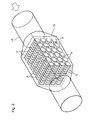
- FIG. 2 is a schematic configuration diagram illustrating a box-type storage case of the power generation system illustrated in FIG. 1.
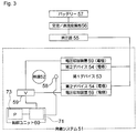
- FIG. 3 is a schematic configuration diagram showing another embodiment of the power generation system of the present invention.
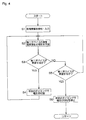
- FIG. 4 is a flowchart showing a control process executed in the control unit of FIG.
- FIG. 5 is a schematic configuration diagram illustrating a configuration in which a power generation system according to another embodiment of the present invention is mounted on a vehicle.
- FIG. 6 is an enlarged view of a main part of the power generation system shown in FIG.
- FIG. 7 is a graph showing the relationship between the voltage application timing and the recovered power in the reference example.
- 1. 1 is a schematic configuration diagram of an embodiment of a power generation system according to the present invention.
- the automobile 8 includes a power system 2 and an energy recovery system 29.
- the power system 2 includes an engine 11 as a heat source whose temperature rises and falls over time, an intake pipe 16 for supplying air to the engine 11, and a flow path through which exhaust gas as a heat medium heated by the engine 11 passes.
- An exhaust pipe 17 and a fuel supply device 20 for supplying fuel to the engine 11 are provided.
- the engine 11 is a device that generates power.
- a single-cylinder type or a multi-cylinder type for example, a 2-cylinder type, a 4-cylinder type, or a 6-cylinder type
- a system for example, a 2-cycle system, a 4-cycle system, a 6-cycle system, etc.
- the engine 11 includes a plurality (four) of cylinders 12 arranged in parallel. In FIG. 1, one cylinder 12 is taken out and the other cylinders 12 are omitted.
- Each cylinder 12 includes a piston 13, a combustion chamber 14, a spark plug (not shown), and the like.
- the upstream side is connected to the intake pipe 16 and the downstream side is connected to the exhaust pipe 17.
- Each cylinder 12 includes an intake valve 18 at a connection portion connected to the intake pipe 16 and an exhaust valve 19 at a connection portion connected to the exhaust pipe 17.
- the intake valve 18 is provided at the connecting portion between the cylinder 12 and the intake pipe 16 so that the cylinder 12 can be opened and closed.
- the exhaust valve 19 is provided at the connecting portion between the cylinder 12 and the exhaust pipe 17 so that the cylinder 12 can be opened and closed.
- the intake valve 18 and the exhaust valve 19 are urged in the closing direction by an elastic force such as a spring.
- the intake valve 18 and the exhaust valve 19 can open and close the cylinder 12 by, for example, rotation of a camshaft.
- the intake pipe 16 is provided to supply air to the engine 11, and its downstream end is connected to the cylinder 12 of the engine 11 and its upstream end is open to the outside air.
- the intake pipe 16 is provided with a throttle valve 27.
- the throttle valve 27 can be opened and closed and the opening thereof can be adjusted in accordance with a driving operation such as depression of an accelerator pedal, for example, and air can be taken into the engine 11 by the opening and closing.
- the exhaust pipe 17 is provided for exhausting exhaust gas from the engine 11, and its upstream end is connected to the cylinder 12 of the engine 11.
- a plurality of (four) exhaust pipes 17 connected to a plurality of (four) cylinders 12 are gathered together at a predetermined location, and downstream of the gathered exhaust pipes 17.
- the catalyst mounting part 24 and the box-type storage case 5 are interposed.
- the catalyst mounting unit 24 includes, for example, a catalyst carrier and a catalyst coated on the carrier, and includes hydrocarbons (HC), nitrogen oxides (NOx), monoxide contained in exhaust gas discharged from the engine 11.
- HC hydrocarbons
- NOx nitrogen oxides
- the exhaust pipe 17 is connected to an intermediate portion in the flow direction of the exhaust gas.
- the box-type storage case 5 is a substantially rectangular parallelepiped storage case that is interposed so as to communicate with the exhaust pipe 17 in the middle of the flow direction downstream of the catalyst mounting portion 24 of the exhaust pipe 17. The exhaust gas passes through.
- the downstream end of the exhaust pipe 17 is open to the outside air. Thereby, the exhaust gas discharged from the engine 11 can be released to the outside air.
- the fuel supply device 20 includes a fuel tank 21 and a fuel supply pipe 22.
- the fuel tank 21 is a tank that stores fuel (for example, gasoline) supplied to the engine 11, and is formed of a heat-resistant pressure-resistant container or the like.
- the fuel supply pipe 22 is provided to supply fuel from the fuel tank 21 to the engine 11, and its upstream end is connected to the fuel tank 21 and its downstream end is connected to the fuel injection valve 23. It is connected.
- the fuel injection valve 23 is a valve for adjusting the amount of fuel supplied from the fuel tank 21 to the engine 11 and injecting the fuel to the engine 11, and is provided at the downstream end of the fuel supply pipe 22. It is provided and connected to the upstream side of the intake valve 18 of the intake pipe 16.
- the fuel injection valve 23 is not particularly limited, and a known injection valve can be used.
- Such a fuel injection valve 23 is electrically connected to an engine control unit 28 of the engine 11, and its opening / closing is controlled by the engine control unit 28.
- the engine control unit 28 operates the engine 11 (for example, the number of revolutions of the engine 11 detected by a tachometer (not shown), for example, in the intake pipe 16 downstream of the throttle valve 27 detected by a pressure sensor (not shown)).
- the fuel injection valve 23 is electrically connected to the engine control unit 28, so that a control signal from the engine control unit 28 can be input to the fuel injection valve 23.
- the engine control unit 28 controls the opening and closing and the opening degree of the fuel injection valve 23, that is, the fuel injection amount (fuel supply amount to the engine 11) by the fuel injection valve 23 in accordance with the operating state of the engine 11. It is possible.
- the energy recovery system 29 includes a power generation element 3 whose temperature increases and decreases over time due to a temperature change of exhaust gas, a power generation device 6 including a first electrode 4 for taking out power from the power generation element 3, and an exhaust pipe 17
- the temperature detection device 7 as temperature detection means for detecting the temperature of the exhaust gas passing through the device
- the voltage application device 9 as voltage application means for applying a voltage to the power generation device 6, and the temperature detection device 7 raise the exhaust gas.
- a control device 10 is provided as a control means for operating the voltage application device 9 when temperature is detected and stopping the voltage application device 9 when temperature drop of the exhaust gas is detected.
- the power generation device 6 is disposed in the box-type storage case 5.
- the power generating element 3 is an element that is discharged from the engine 11 and is electrically polarized by increasing or decreasing the temperature with time by supplying exhaust gas whose temperature increases or decreases with time.
- the electric polarization referred to here is a phenomenon in which a potential difference occurs due to dielectric polarization due to displacement of positive and negative ions due to crystal distortion, such as a piezo effect and / or a phenomenon in which a dielectric constant changes due to a temperature change and a potential difference occurs, It is defined as a phenomenon in which an electromotive force is generated in a material, such as an effect.
- Such a power generating element 3 include an element that is electrically polarized by a piezo effect and an element that is electrically polarized by a pyroelectric effect.
- the piezo effect is an effect (phenomenon) in which when stress or strain is applied, it is electrically polarized according to the magnitude of the stress or strain.
- the power generating element 3 that is electrically polarized by such a piezoelectric effect is not particularly limited, and a known piezoelectric element (piezoelectric element) can be used.
- the piezo element When a piezo element is used as the power generation element 3, the piezo element is disposed in the box-type storage case 5 so that, for example, the periphery thereof is fixed by a fixing member and is exposed (exposed) to exhaust gas. .
- the fixing member is not particularly limited, and for example, a first electrode 4 described later can be used.
- the piezo element is heated or cooled by the temperature change of the exhaust gas with time, and thereby expands or contracts.
- such a piezo element is normally maintained in a heated state or a cooled state, and when its temperature becomes constant (that is, a constant volume), the electric polarization is neutralized, and then cooled or heated, Again, it is electrically polarized.
- the piezo element is repeatedly heated and cooled over time. Electrical polarization and its neutralization are repeated over time.
- electric power is taken out as a waveform (for example, alternating current, pulsating flow, etc.) that varies with time by the first electrode 4 described later.
- a waveform for example, alternating current, pulsating flow, etc.
- the pyroelectric effect is, for example, an effect (phenomenon) in which the dielectric is electrically polarized in accordance with a change in temperature when the dielectric (insulator) is heated and cooled, and includes the first effect and the second effect. It is out.
- the first effect is an effect that, when the dielectric is heated and cooled, it spontaneously polarizes due to the temperature change and generates a charge on the surface of the dielectric.
- the second effect is the effect of pressure deformation in the crystal structure due to temperature changes during heating and cooling of the dielectric, and piezoelectric polarization due to stress or strain applied to the crystal structure (piezo effect, piezoelectric effect). ).
- the element that is electrically polarized by such a pyroelectric effect is not particularly limited, and a known pyroelectric element can be used.
- the pyroelectric element When a pyroelectric element is used as the power generation element 3, the pyroelectric element is arranged in the box-type storage case 5 so as to be in contact (exposed) with the exhaust gas.
- the pyroelectric element is heated or cooled by the temperature change of the exhaust gas over time, and is electrically polarized by the pyroelectric effect (including the first effect and the second effect). Thereby, although mentioned later in detail, electric power is taken out from the pyroelectric element via the first electrode 4.
- Such pyroelectric elements are usually maintained in a heated state or a cooled state, and when the temperature becomes constant, the electric polarization is neutralized, and then cooled or heated again to be electrically polarized again. .
- the pyroelectric element is repeatedly heated and cooled over time.
- the electrical polarization of the element and its neutralization are repeated over time.
- electric power is taken out as a waveform (for example, alternating current, pulsating flow, etc.) that varies with time by the first electrode 4 described later.
- a waveform for example, alternating current, pulsating flow, etc.
- Such a power generation element 3 is a dielectric having a Curie point.
- a known element for example, a known pyroelectric element (for example, BaTiO 3 , CaTiO 3 , (CaBi ) TiO 3 , BaNd 2 Ti 5 O 14 , BaSm 2 Ti 4 O 12 , lead zirconate titanate (PZT: Pb (Zr, Ti) O 3 ), etc.), known piezo elements (eg, quartz (SiO 2 )) Etc.), zinc oxide (ZnO), Rochelle salt (potassium tartrate-sodium) (KNaC 4 H 4 O 6 ), lead zirconate titanate (PZT: Pb (Zr, Ti) O 3 ), lithium niobate (LiNbO 3) ), Lithium tantalate (LiTaO 3 ), lithium tetraborate (Li 2 B 4 O 7 ), langasite (La 3 Ga 5
- These power generating elements 3 can be used alone or in combination of two or more.
- the Curie point of the power generation element 3 is, for example, ⁇ 77 ° C. or higher, preferably ⁇ 10 ° C. or higher, for example, 1300 ° C. or lower, preferably 900 ° C. or lower.
- the relative dielectric constant of the power generating element 3 is, for example, 1 or more, preferably 100 or more, and more preferably 2000 or more.
- the power generation element 3 (dielectric (insulator)) is electrically polarized by the temperature change of the exhaust gas, and the electrical polarization may be any of electronic polarization, ion polarization, and orientation polarization.
- a material for example, a liquid crystal material
- polarization by orientation polarization it is expected that power generation efficiency can be improved by changing the molecular structure.
- a plurality of such power generating elements 3 are arranged in a box-type housing case 5 with a space therebetween, for example, as shown in FIG. 2, and a first electrode 4 (and a fixing member provided if necessary) to be described later. (Not shown).
- Each of the plurality of power generation elements 3 is arranged in the box-type storage case 5 so that the longitudinal direction thereof is along the flow direction of the exhaust gas, and each power generation element 3 is directly or first electrode 4 (described later). ) To be able to contact (expose) exhaust gas.
- one power generation element 3 (power generation device 6) is taken out and shown, and the other power generation elements 3 (power generation devices 6) are omitted.
- the first electrode 4 is provided in order to take out electric power from the power generation element 3.
- the first electrode 4 is not particularly limited, but, for example, two electrodes (for example, a copper electrode, a silver electrode, and the like) disposed to face each other with the power generation element 3 interposed therebetween, for example, these A conducting wire or the like connected to the electrode is provided, and is electrically connected to the power generation element 3.
- the temperature detection device 7 is disposed in the exhaust pipe 17 on the upstream side of the box-type storage case 5 where the power generation device 6 is installed, and is supported near the center in the exhaust pipe 17 via a frame (not shown).
- the distance between the temperature detection device 7 and the power generation element 3 (power generation device 6) is not particularly limited.
- the temperature of the exhaust gas from the engine 11 changes at a frequency of 50 Hz, and
- the flow velocity is 10 m / s, 20 cm with respect to the upstream end portion of the power generation element 3 on the upstream side of the power generation element 3 (power generation device 6) in the box-type storage case 5 in the exhaust pipe 17. It is preferable to arrange them within an interval.
- the temperature detection device 7 includes a temperature detection element 35 and a second electrode 36.
- the temperature detection element 35 is an element that is discharged from the engine 11 and supplied with exhaust gas whose temperature rises and falls over time, so that the temperature rises and falls over time and is thereby electrically polarized. That is, the temperature detection element 35 is the above-described element (for example, a piezo element, a pyroelectric element, or the like), and specifically, is a dielectric having a Curie point.
- the piezo element When a piezo element is used as the temperature detecting element 35, the piezo element is disposed in the exhaust pipe 17 so that, for example, the periphery thereof is fixed by a fixing member and is in contact (exposed) with the exhaust gas.
- the fixing member is not particularly limited, and for example, a second electrode 36 described later can be used.
- the piezo element is heated or cooled by the temperature change of the exhaust gas with time, and thereby expands or contracts.
- the pyroelectric element When a pyroelectric element is used as the temperature detection element 35, the pyroelectric element is disposed in the exhaust pipe 17 so as to be in contact with (exposed to) the exhaust gas.
- the pyroelectric element is heated or cooled by the temperature change of the exhaust gas over time, and is electrically polarized by the pyroelectric effect (including the first effect and the second effect).
- an electromotive force is detected from the pyroelectric element via the second electrode 36.
- the electromotive force detected by the second electrode 36 from the temperature sensing element 35 is a waveform that varies over time (for example, alternating current, pulsating current, etc.), similar to the power extracted from the power generating element 3 by the first electrode 4. Detected as
- These temperature detection elements 35 can be used alone or in combination of two or more.
- Examples of the dielectric that constitutes the temperature detection element 35 include those exemplified as the dielectric that constitutes the power generation element 3.
- the dielectric that constitutes the temperature detection element 35 and the dielectric that constitutes the power generation element 3 The same type.
- the Curie point of the temperature detecting element 35 is, for example, ⁇ 77 ° C. or higher, preferably ⁇ 10 ° C. or higher, and for example, 1300 ° C. or lower, preferably 900 ° C. or lower.
- the Curie point of the dielectric constituting the temperature detecting element 35 of the same type as the dielectric constituting the power generation element 3 is 50 ° C. lower than the Curie point of the dielectric constituting the power generation element 3,
- the temperature is 10 ° C. or lower.
- such a dielectric is defined as a dielectric having the same specifications as the dielectric constituting the power generating element.
- the Curie point of the temperature detection element 35 and the Curie point of the power generation element 3 are preferably the same, and more preferably, the temperature detection element 35 and the power generation element 3 are the same element. is there.
- the relative dielectric constant of the power generating element 3 is, for example, 1 or more, preferably 100 or more, and more preferably 2000 or more.
- the second electrode 36 is provided to detect an electromotive force from the temperature detection element 35 and to detect the electric polarization of the temperature detection element 35.
- the second electrode 36 is not particularly limited as long as it can detect an electromotive force from the temperature detection element 35 and detect the electric polarization of the temperature detection element 35.
- Two electrodes for example, a copper electrode, a silver electrode, etc.
- a conductive wire connected to these electrodes are provided, and are electrically connected to the temperature detection element 35.
- the voltage application device 9 is provided directly or close to the power generation element 3 (power generation device 6) in order to apply a voltage to the power generation element 3 (power generation device 6).
- the voltage application device 9 includes, for example, two voltage application electrodes 37 (for example, copper electrodes) that are arranged opposite to each other with the power generation element 3 and the first electrode 4 interposed therebetween, separately from the first electrode 4 described above.
- the control device 10 is a unit (for example, ECU: Electronic Control Unit) that performs electrical control in the power generation system 1, and is configured by a microcomputer including a CPU, a ROM, a RAM, and the like.
- the control device 10 is electrically connected to the temperature detection device 7 and the voltage application device 9, and will be described in detail later.
- the temperature detection device 7 detects the temperature rise or the temperature fall of the exhaust gas, Then, the voltage application device 9 is activated or stopped.
- the energy recovery system 29 further includes a booster 30, an AC / DC converter 31 (AC-DC converter), and a battery 32.
- the booster 30, the AC / DC converter 31 and the battery 32 are electrically connected to the first electrode 4.
- the power generation system 1 includes the temperature detection device 7 including 36, the voltage application device 9, and the control device 10. 2. Power Generation Method Hereinafter, a power generation method using the above power generation system 1 will be described in detail.
- the piston 11 is repeatedly moved up and down in the cylinder 12 by driving the engine 11.
- the intake process, the compression process, the explosion process, the exhaust process, and the like are sequentially performed. Is done.
- the throttle valve 27 is opened, air is supplied from the intake pipe 16, and a predetermined amount of fuel is supplied (injected) from the fuel supply pipe 22 by the fuel injection valve 23. And they are mixed. Then, the air-fuel mixture is supplied to the combustion chamber 14 of the cylinder 12 by opening the intake valve 18 (intake process).
- the air-fuel mixture is ignited by an unillustrated spark plug and burned explosively, and the piston 13 is pushed down by the explosion (explosion process).
- each cylinder 12 passes through the exhaust pipe 17 connected to each cylinder 12 and is gathered together at a predetermined location, and then passes through the catalyst mounting portion 24 and by the catalyst. After purification and contact with the temperature detection device 7, the air is released to the outside air through the box-type storage case 5.
- the temperature of the engine 11 and the exhaust gas discharged from the engine 11 rises and falls over time according to, for example, the driving state of the automobile 8 (driving state of the engine 11).
- the driving and stopping of the engine 11 are repeated over time, whereby the running and stopping of the automobile 8 are controlled.
- the temperature of the engine 11 is set to a high temperature state, and when the engine 11 is stopped, the temperature of the engine 11 is set to a low temperature state.
- the temperature of the engine 11 includes, for example, the load (vehicle weight, road surface inclination, etc.), the vehicle speed, the accelerator opening degree, the rotation speed of the engine 11, the intake pressure in the intake system, and the intake air amount when the automobile 8 is traveling. It also changes depending on the fuel flow rate, and also the air-fuel ratio (intake air amount / fuel flow rate), etc., and goes up and down over time.
- the load vehicle weight, road surface inclination, etc.
- the temperature of the engine 11 includes, for example, the load (vehicle weight, road surface inclination, etc.), the vehicle speed, the accelerator opening degree, the rotation speed of the engine 11, the intake pressure in the intake system, and the intake air amount when the automobile 8 is traveling. It also changes depending on the fuel flow rate, and also the air-fuel ratio (intake air amount / fuel flow rate), etc., and goes up and down over time.
- the temperature of the exhaust gas (the internal temperature of the exhaust pipe 17 and the box-type storage case 5) increases or decreases over time according to the state of the engine 11. To do.
- the temperature of the engine 11 and the exhaust gas is, for example, 200 to 1200 ° C., preferably 700 to 900 ° C. in the high temperature state, and the temperature in the low temperature state is the above high temperature state. More specifically, it is, for example, 100 to 800 ° C., preferably 200 to 500 ° C., and the temperature difference between the high temperature state and the low temperature state is, for example, 10 to 600 ° C., preferably 20 to 500 ° C.
- the temperature detection device including the box-type storage case 5 and the temperature detection element 35 and the second electrode 36 on the upstream side of the box-type storage case 5. 7 and the second electrode 36 is electrically connected to the control device 10.
- a plurality of power generation devices 6 including the power generation element 3 and the first electrode 4 and voltage application electrodes 37 are arranged in alignment, and the voltage application electrode 37 (voltage application device 9) is electrically connected to the control device 10. Connected.
- the exhaust gas discharged from the engine 11 first comes into contact with the temperature detection element 35.
- the thermal energy of the engine 11 is transmitted to the temperature detection element 35 via the exhaust gas, and the temperature detection element 35 is heated and / or cooled. That is, the temperature detection element 35 is heated and / or cooled by the temperature change with time of the engine 11 and the exhaust gas that transfers the heat of the engine 11.
- the temperature detection element 35 can be brought into a high temperature state or a low temperature state with time, and the temperature detection element 35 can have an effect (for example, a piezo effect) according to the element (for example, a piezo element or a pyroelectric element).
- the pyroelectric effect, etc.), and the electromotive force can be detected as a waveform (for example, alternating current, pulsating current, etc.) that varies with time from the temperature sensing element 35 via the second electrode 36. be able to.
- the electromotive force detected from the temperature detection element 35 is transmitted as an electric signal to the control device 10 to detect whether the temperature detection element 35 is in a temperature rising state or a temperature falling state. That is, by detecting the state of the temperature detection element 35, it is determined whether the exhaust gas and the power generation element 3 are in a temperature rising state or a temperature falling state. More specifically, for example, when the electromotive force detected from the temperature detection element 35 varies more than a predetermined value (for example, +1 mV / s), the temperature detection element 35 is heated. It is detected that the exhaust gas and the power generation element 3 are in the temperature rising state.
- a predetermined value for example, +1 mV / s
- the temperature detection element 35 when the electromotive force detected from the temperature detection element 35 fluctuates more than a predetermined value (for example, -1 mV / s) set in advance, the temperature detection element 35 is detected as being in a temperature-decreasing state.
- the exhaust gas and the power generation element 3 are also determined to be in the temperature-decreasing state.
- the voltage application device 9 is operated by the control device 10, and a predetermined voltage (for example, the power generation device 6) is applied to the power generation element 3 (power generation device 6). , 50-1000V).
- the time during which the voltage is applied is until the temperature detecting element 35 reaches the temperature-decreasing state. Specifically, the temperature is being increased.
- the control device 10 stops the voltage application device 9 and stops the application of voltage to the power generation element 3 (power generation device 6).
- the time during which the voltage application is stopped is until the temperature detecting element 35 reaches the temperature rising state, and is specifically in the temperature falling state.
- the time required from when the voltage applying device 9 is activated until the voltage is applied (that is, the intensity of the electric field reaches the predetermined value), and after the voltage applying device 9 is stopped, the electric field
- the time required until the strength reaches 0 kV / mm can be regarded as substantially 0 second.
- the time during which the voltage less than the predetermined value is applied is substantially 0 second, and the voltage is applied when the voltage of the predetermined value is applied (ON).
- the state where it is not applied (OFF) is switched by the control device 10.
- the voltage application device 9 is activated and a voltage is applied to the power generation element 3 (power generation device 6).
- the voltage applying device 9 is stopped and the voltage application is stopped.
- the thermal energy of the engine 11 is transmitted to the power generation element 3 through the exhaust gas, and the power generation element 3 is heated and / or cooled. That is, the power generation element 3 is heated and / or cooled by the temperature change of the engine 11 and the exhaust gas that transmits the heat of the engine 11 over time.
- the power generation element 3 can be brought into a high temperature state or a low temperature state with time, and the power generation element 3 can be brought into an effect (for example, a piezoelectric element, a pyroelectric element, etc.) according to the element (for example, a piezoelectric element). Effect, pyroelectric effect, etc.).
- each power generation element 3 power can be extracted from each power generation element 3 as a waveform (for example, alternating current, pulsating current) that varies with time through the first electrode 4.
- a waveform for example, alternating current, pulsating current
- the electric power obtained as described above is boosted by a booster 30 connected to the first electrode 4 as necessary, and a direct current is converted by an AC / DC converter 31. After conversion to voltage, the battery 32 is charged.
- the electric power stored in the battery 32 can be appropriately used as the power of the automobile 8 and various electric components mounted on the automobile 8.
- the temperature detection element 35 composed of a dielectric having the same specifications as that of the dielectric constituting the power generation element 3 is used, the temperature change between the power generation element 3 and the temperature detection element 35. Can be the same or close to each other.
- the temperature of the power generation element 3 is detected by a temperature sensor using a thermocouple, or when the temperature prediction system technique for predicting the temperature of the power generation element 3 from the driving state of the engine 11 or the like is used. If this power generation system 1 is used, since the same type of element (dielectric having a Curie point) as the power generation element 3 is used for the temperature detection element 35, the responsiveness to temperature change is further improved, and the power generation element 3 can be the same as or close to the response to the temperature change.
- the power generation element 3 and the temperature detection element 35 are not heated or lowered depending on the heating and / or cooling method, and are kept at a constant temperature (substantially no temperature change).
- the electromotive force detected from the temperature detection element 35 is temporarily maintained at a predetermined value (for example, less than 1 mV / s).
- the voltage is applied during the temperature rise of the temperature detecting element 35 and during the constant temperature state after the temperature rise, and the voltage application is stopped during the temperature drop and during the constant temperature state after the temperature drop. Note that when the power system 2 of the automobile 8 is employed as a heat source, the power generation element 3 and the temperature detection element 35 are repeated in the temperature rising state and the temperature lowering state without being substantially in a constant temperature state.
- the power system 2 is used as a heat source.
- the heat source is not limited to the above, and various energy utilization devices such as an internal combustion engine and a light emitting device can be used. In such a case, various heat media such as light and air are selected.
- the heat source is the internal combustion engine and the power system 2, and the heat medium is exhaust gas. More preferably, the heat source is the power system 2.
- the temperature detection device 7 is disposed at an interval of, for example, 20 cm or less with respect to the upstream end portion of the power generation device 6 in the box-type storage case 5.
- the timing at which the voltage applying device 9 applies the voltage can be advanced or delayed by the control device 10.
- control device 10 and the engine control unit 28 have been described as separate devices, but they can also be formed as a single control unit (such as an ECU).
- the first electrode 4 and the voltage application electrode 37 are described as separate electrodes, but they can also be formed as one electrode.
- FIG. 3 is a schematic configuration diagram showing another embodiment of the power generation system of the present invention.
- a power generation system 51 includes a heat source 52 whose temperature rises and falls with time, a first device 53 whose temperature rises and falls with time due to a temperature change of the heat source 52, and electric power from the first device 53.
- a second device 54 for taking out, a voltage applying device 59 as voltage applying means for applying a voltage to the first device 53, and a control unit 60 for operating and stopping the voltage applying device 59 are provided.
- the heat source 52 is not particularly limited as long as it is a heat source whose temperature rises and falls over time, specifically, a heat source whose temperature changes periodically over time.
- various energy utilization devices such as an internal combustion engine and a light emitting device Is mentioned.
- An internal combustion engine is a device that outputs power, for example, for a vehicle.
- a single cylinder type or a multi-cylinder type is adopted, and a multi-cycle type (for example, a 2-cycle type, a 4-cycle type) is used in each cylinder. System, 6-cycle system, etc.) are employed.
- pistons are repeatedly moved up and down in each cylinder.
- an intake process, a compression process, an explosion process, an exhaust process, and the like are sequentially performed, and fuel is discharged. It is burned and power is output.
- the amount of exhaust gas in the exhaust gas pipe is reduced, so that the internal temperature of the exhaust gas pipe decreases compared to the exhaust process.
- the temperature of the internal combustion engine rises in the exhaust process and falls in the intake process, the compression process, and the explosion process, that is, rises and falls over time.
- each of the above steps is periodically and sequentially repeated according to the piston cycle
- the inside of the exhaust gas pipe of each cylinder in the internal combustion engine is periodically cycled with the repetition cycle of each of the above steps.
- a temperature change more specifically, a high temperature state and a low temperature state are periodically repeated.
- the temperature of the light emitting device rises due to the heat energy using light such as infrared rays and visible light as a heat medium. Therefore, the temperature of the light emitting device increases and decreases over time by turning on (emitting) and turning off over time.
- the light-emitting device is a light-emitting device (blinking (flashing) type light-emitting device) in which lighting is turned on and off intermittently over time
- the light-emitting device is turned on (light-emitting). Due to the thermal energy of the light, a temperature change periodically, more specifically, a high temperature state and a low temperature state are periodically repeated.
- the heat source 52 for example, a plurality of heat sources are provided, and a temperature change can be caused by switching between the plurality of heat sources.
- two heat sources a low-temperature heat source (such as a coolant) and a high-temperature heat source (eg, a heating material) having a higher temperature than the low-temperature heat source, are prepared as the heat source.
- a low-temperature heat source such as a coolant
- a high-temperature heat source eg, a heating material
- the temperature as the heat source can be increased or decreased over time, and in particular, the temperature can be periodically changed by periodically switching the low temperature heat source and the high temperature heat source.
- the heat source 52 including a plurality of heat sources that can be switched is not particularly limited.
- high-temperature air including a combustion low-temperature air supply system, a heat storage heat exchanger, a high-temperature gas exhaust system, and a supply / exhaust switching valve Combustion furnace (for example, a high-temperature gas generator described in Republished No. 96-5474), for example, a seawater exchange device using a high-temperature heat source, a low-temperature heat source, and a hydrogen storage alloy (hydrogen storage alloy actuator type seawater exchange device), etc. Is mentioned.
- These heat sources 52 can be used alone or in combination of two or more.
- the heat source 52 is preferably an internal combustion engine.
- the first device 53 is a device that is electrically polarized in accordance with the temperature change of the heat source 52.
- the electric polarization referred to here is a phenomenon in which a potential difference occurs due to dielectric polarization due to displacement of positive and negative ions due to crystal distortion, such as a piezo effect and / or a phenomenon in which a dielectric constant changes due to a temperature change and a potential difference occurs, It is defined as a phenomenon in which an electromotive force is generated in a material, such as an effect.
- examples of the first device 53 include a device that is electrically polarized by a piezo effect, a device that is electrically polarized by a pyroelectric effect, and the like.
- the piezo effect is an effect (phenomenon) in which when stress or strain is applied, it is electrically polarized according to the magnitude of the stress or strain.
- the first device 53 that is electrically polarized by such a piezo effect is not particularly limited, and a known piezo element (piezoelectric element) can be used.
- the piezo element is, for example, a heat medium that is fixed by a fixing member and contacts the heat source 52 or transmits heat from the heat source 52 (described above). (Exhaust gas, light, etc.).
- the fixing member is not particularly limited, and for example, a second device 54 (for example, an electrode) described later can be used.
- the piezo element is heated or cooled (possibly via a heat medium (exhaust gas, light, etc.) as described above) due to a temperature change of the heat source 52 with time, and thereby expands. Or shrink.
- a heat medium exhaust gas, light, etc.
- the piezo element is pressed by the fixing member and is electrically polarized by the piezo effect (piezoelectric effect) or phase transformation near the Curie point. . Thereby, as will be described in detail later, electric power is taken out from the piezo element via the second device 54.
- such a piezo element is normally maintained in a heated state or a cooled state, and when its temperature becomes constant (that is, a constant volume), the electric polarization is neutralized, and then cooled or heated, Again, it is electrically polarized.
- the piezo element is periodically heated and cooled. Electrical polarization and its neutralization are repeated periodically.
- electric power is extracted as a waveform (for example, alternating current, pulsating current) that periodically fluctuates by the second device 54 described later.
- a waveform for example, alternating current, pulsating current
- the pyroelectric effect is, for example, an effect (phenomenon) in which the insulator is electrically polarized in accordance with a change in temperature when the insulator (dielectric) is heated and cooled, and includes the first effect and the second effect. It is out.
- the first effect is an effect in which, when the insulator is heated and cooled, it spontaneously polarizes due to the temperature change and generates a charge on the surface of the insulator.
- the second effect is an effect that pressure deformation occurs in the crystal structure due to temperature changes during heating and cooling of the insulator, and piezoelectric polarization occurs due to stress or strain applied to the crystal structure (piezo effect, piezoelectric effect). ).
- the device that is electrically polarized by such a pyroelectric effect is not particularly limited, and a known pyroelectric element can be used.
- the pyroelectric element When a pyroelectric element is used as the first device 53, the pyroelectric element is in contact with the heat source 52 or in contact with a heat medium (exhaust gas, light, or the like) that transmits the heat of the heat source 52 ( To be exposed).
- a heat medium exhaust gas, light, or the like
- the pyroelectric element is heated or cooled (possibly via a heat medium (exhaust gas, light, etc.) as described above) due to the temperature change of the heat source 52 with time, and the pyroelectric effect (first The electric polarization is caused by the first effect and the second effect.
- power is taken out from the pyroelectric element via the second device 54.
- Such pyroelectric elements are usually maintained in a heated state or a cooled state, and when the temperature becomes constant, the electric polarization is neutralized, and then cooled or heated again to be electrically polarized again. .
- the pyroelectric element is periodically heated and cooled.
- the electrical polarization of the element and its neutralization are repeated periodically.
- electric power is extracted as a waveform (for example, alternating current, pulsating current) that periodically fluctuates by the second device 54 described later.
- a waveform for example, alternating current, pulsating current
- These first devices 53 can be used alone or in combination of two or more.
- a known pyroelectric element for example, BaTiO 3 , CaTiO 3 , (CaBi) TiO 3 , BaNd 2 Ti 5 O 14 , BaSm 2 Ti 4).
- lead zirconate titanate Pb (Zr, Ti) O 3
- known piezo elements eg quartz (SiO 2 ), zinc oxide (ZnO), Rochelle salt (potassium tartrate-sodium) (KNaC 4 H 4 O 6)
- lead zirconate titanate PZT: Pb (Zr, Ti ) O 3
- lithium niobate LiNbO 3
- lithium tantalate LiTaO 3
- lithium tetraborate Li 2 B 4 O 7
- langasite La 3 Ga 5 SiO 14
- aluminum nitride AlN
- tourmaline tourmaline
- Vinylidene fluoride PVDF
- the Curie point of the first device 53 is, for example, ⁇ 77 ° C. or higher, preferably ⁇ 10 ° C. or higher, for example, 1300 ° C. or lower, preferably 900 ° C. or lower.
- the relative dielectric constant of the first device 53 is, for example, 1 or more, preferably 100 or more, more preferably 2000 or more.
- the higher the relative permittivity of the first device 53 insulator (dielectric)
- the higher the energy conversion efficiency and the higher voltage can be taken out. If the relative dielectric constant is less than the above lower limit, the energy conversion efficiency is low, and the voltage of the obtained power may be low.
- the first device 53 (insulator (dielectric)) is electrically polarized by the temperature change of the heat source 52.
- the electrical polarization may be any of electronic polarization, ion polarization, and orientation polarization.
- a material for example, a liquid crystal material
- polarization by orientation polarization it is expected that power generation efficiency can be improved by changing the molecular structure.
- the second device 54 is provided to extract power from the first device 53.
- the second device 54 is not particularly limited.
- two electrodes for example, a copper electrode, a silver electrode, and the like
- the first device 53 interposed therebetween, for example, ., And the like, and are electrically connected to the first device 53.
- the voltage application device 59 is provided directly or close to the first device 53 in order to apply a voltage to the first device 53.
- the voltage application device 59 includes, for example, two electrodes (for example, a copper electrode, a silver electrode, and the like) that are disposed opposite to each other with the first device 53 interposed therebetween, separately from the second device 54 described above.
- a voltage application power source V and a conductive wire connected to the voltage application power source V are provided, and the first device 53 and the second device 54 are disposed between the electrodes.
- the control unit 60 is a unit (for example, ECU: Electronic Control Unit) that performs electrical control in the power generation system 51, and includes a microcomputer that includes a memory 73 and a central processing unit (CPU) 71. .
- ECU Electronic Control Unit
- CPU central processing unit
- the memory 73 includes a ROM and a RAM, and various programs and fixed data are stored in the ROM, and temporary input data is stored in the RAM.
- the ROM of the memory 73 stores a temperature prediction program P as a prediction means for predicting the temperature of the first device 53.
- the temperature prediction program P is a program that predicts the temperature of the first device 53 and the cycle of the temperature change from the operating state of the heat source 52, the temperature transition (history) of the first device 53, and the like. It is created based on the data.
- the central processing unit (CPU) 71 is electrically connected to various detection devices such as an output meter of the heat source 52 and a thermometer (such as a thermocouple) that measures the temperature of the first device 53. It is connected and various data can be input. Thereby, temporary numerical values for processing the temperature prediction program P such as the operating state of the heat source 52 and the temperature transition (history) of the first device 53 are input and stored in the RAM of the memory 73. Is done.
- the central processing unit (CPU) 71 is a control means for predicting and calculating the temperature based on the temperature prediction program P in the memory 73, and for operating and stopping the voltage application device 59 based on the predicted temperature. As shown, it is electrically connected to the memory 73 and electrically connected to the voltage applying device 59.
- the information detected by the above-described detection devices (the output meter of the heat source 52, the thermometer of the first device 53, etc.) Based on this, the temperature of the first device 53 can be predicted.
- the central processing unit (CPU) 71 can operate and stop the voltage application device 59 based on the temperature state of the first device 53 predicted by the temperature prediction program P.
- the second device 54 is electrically connected to the booster 55, the AC / DC converter (AC-DC converter) 56, and the battery 57 sequentially.
- AC-DC converter AC-DC converter
- the temperature of the heat source 52 is changed over time, specifically, periodically, and the first device 53 is heated by the heat source 52. And / or cool.
- the above-mentioned first device 53 is periodically electrically polarized. Thereafter, the electric power is extracted as a waveform (for example, alternating current, pulsating current, etc.) that periodically fluctuates according to the periodic electric polarization of the first device 53 via the second device 54.
- a waveform for example, alternating current, pulsating current, etc.
- the temperature of the heat source 52 is, for example, 200 to 1200 ° C., preferably 700 to 900 ° C. in the high temperature state, and the temperature in the low temperature state is lower than the temperature in the high temperature state. More specifically, for example, the temperature is 100 to 800 ° C., preferably 200 to 500 ° C., and the temperature difference between the high temperature state and the low temperature state is 10 to 600 ° C., preferably 20 to 500 ° C. is there.
- the repetition cycle between the high temperature state and the low temperature state is, for example, 10 to 400 cycles / second, preferably 30 to 100 cycles / second.
- a voltage is applied to the first device 53 in accordance with the temperature state of the first device 53 in order to generate power more efficiently.
- the temperature of the first device 53 is predicted by the temperature prediction program P described above together with the heating and / or cooling by the heat source 52, and the first device predicted by the temperature prediction program P is predicted.
- the voltage application device 59 is activated and stopped under the control of the central processing unit (CPU) 71.
- FIG. 4 is a flowchart showing a control process executed in the control unit 60 of FIG.
- the control process (temperature prediction program P) shown in FIG. 4 is stored in the ROM of the memory 73, and the control process is executed by the central processing unit (CPU) 71.
- CPU central processing unit
- This control process is started with the start of operation of the heat source 52 as a trigger.
- the temperature change of the first device 53 after that is based on the operating state of the heat source 52 detected and input as described above, the transition (history) of the temperature of the first device 53 before that, and the like.
- the period of the temperature change of the first device 53 is predicted (S2).
- the calculation method for predicting the temperature change and the cycle of the first device 53 is not particularly limited, and a known method can be adopted.
- the temperature change period of the first device 53 (time required for one cycle of heating and cooling) is, for example, 0.01 seconds or more, preferably 0.02 seconds or more, for example, 40 seconds or less, preferably 20 seconds or less.
- this electric power generation system 51 it is predicted whether the 1st device 53 will heat up according to the temperature prediction program P (S3).
- the temperature prediction program P for example, when the temperature of the first device 53 increases by a predetermined value (for example, 0.2 ° C./s), it is determined that the temperature is in the raised state.
- the temperature increase start time is predicted according to the temperature prediction program P.
- the voltage application device 59 is operated by the central processing unit (CPU) 21 at a timing that is not less than ⁇ 15% and less than 0% of the temperature change period of the first device 53 from the time when the temperature rise is expected to start.
- a predetermined voltage is applied to the first device 53 (S4).
- the voltage application device has a timing that is earlier by a predetermined time than the time at which the temperature increase of the first device 53 is predicted ( ⁇ 15% or more and less than 0% with respect to the time of one temperature change period). 59 is activated.
- the strength of the electric field is, for example, 0.2 kV / mm or more, preferably 0.4 kV / mm or more, for example, 5 kV / mm or less, preferably 4 kV / mm or less.
- the applied voltage electric field
- the amount of energy extracted from the first device 53 and the amount of energy consumed by the voltage application device 59 can be balanced, and power can be generated with excellent efficiency. it can.
- the temperature rise of the first device 53 is not predicted (S3: NO)
- a predetermined value for example, 0.2 ° C./s
- the temperature start time is predicted according to the temperature prediction program P.
- the voltage application device 9 is stopped by the central processing unit (CPU) 71 at a timing of ⁇ 15% or more and less than 0% of the period of temperature change of the first device 53 from the time at which the start of temperature decrease is predicted, Application of voltage to the first device 53 is stopped (S6).
- CPU central processing unit
- the voltage application device 59 is operated at a timing earlier than the time when the first device 53 is expected to start to cool down by a predetermined time ( ⁇ 15% or more and less than 0% with respect to the time of one temperature change period). Stopped.
- the first device 53 is heated and / or cooled by the internal combustion engine.
- the temperature drop state is repeated.
- the time required from when the voltage applying device 59 is activated until the voltage is applied (that is, the electric field reaches the predetermined value), and after the voltage applying device 59 is stopped, the electric field
- the time required to reach 0 kV / mm can be regarded as substantially 0 second. That is, in such a power generation system 51, the time during which the voltage less than the predetermined value is applied is substantially 0 seconds, and the state in which the voltage of the predetermined value is applied (ON), A state where no voltage is applied (OFF) is switched by a central processing unit (CPU) 71.
- CPU central processing unit
- the voltage application device 59 is operated at a timing that is not less than ⁇ 15% and less than 0% of the period from the time at which the temperature rise of the first device 53 is predicted to start. Then, the voltage application device 59 is stopped at a timing that is not less than ⁇ 15% and less than 0% of the period from the time when the start of temperature drop is predicted.
- the voltage is applied at a timing earlier than the time when the start of the temperature increase is predicted by a predetermined time (-15% or more and less than 0% with respect to the time of one temperature change period).
- the application device 59 is activated.
- the voltage application device 59 is stopped at a timing earlier than the time when the start of the temperature decrease is predicted by a predetermined time (-15% or more and less than 0% with respect to the time of one temperature change period).
- the voltage application device 59 is not simply operated and stopped as described above. For example, the magnitude of the applied voltage is changed according to the temperature state of the first device 53. It is also considered to make it. However, such a method requires a cumbersome operation of gradually increasing or decreasing the applied voltage, which is troublesome.
- the power generation efficiency can be improved by a relatively simple method of operating or stopping the voltage application device 59.
- the extracted power is boosted in a state of a waveform (for example, alternating current, pulsating current) that periodically varies in a booster 55 connected to the second device 54.
- a booster 55 a booster capable of boosting AC voltage with excellent efficiency by a simple configuration using, for example, a coil, a capacitor, or the like is used.
- the electric power boosted by the booster 55 is converted into a DC voltage by the AC / DC converter 56 and then stored in the battery 57.
- a fluctuating voltage for example, AC voltage
- DC voltage constant voltage
- the heat source 52 is a heat source that periodically changes in temperature, it is possible to extract electric power as a waveform that periodically fluctuates. can do.
- FIG. 5 is a schematic configuration diagram illustrating a configuration in which a power generation system according to an embodiment of the present invention is mounted on a vehicle
- FIG. 6 is an enlarged view of a main part of the power generation system shown in FIG.
- the automobile 75 includes an internal combustion engine 61, a catalyst mounting portion 62, an exhaust pipe 63, a muffler 64, and a discharge pipe 65.
- the internal combustion engine 61 includes an engine 66 and an exhaust manifold 67.
- the engine 66 is a multi-cylinder (4-cylinder) multi-cycle (4-cycle) type engine, and an upstream end portion of a branch pipe 68 (described later) of the exhaust manifold 67 is connected to each cylinder.
- the exhaust manifold 67 is an exhaust manifold provided for converging exhaust gas discharged from each cylinder of the engine 66, and a plurality of (four) branch pipes 68 (these are connected to each cylinder of the engine 66). 5 are referred to as the branch pipe 68a, the branch pipe 68b, the branch pipe 68c, and the branch pipe 68d in this order from the upper side in FIG. And an air collecting tube 69 that integrates 68 into one.
- each branch pipe 68 is provided with one box-shaped space 70 in the middle of the flow direction.
- the box-shaped space 70 is a substantially rectangular parallelepiped space interposed so as to communicate with the branch pipe 68.
- a plurality of first devices 53 and second devices 54 are provided inside the box-shaped space 70. (See FIG. 6).
- the plurality of first devices 53 are simplified, one first device 53 is shown for one box-shaped space 70, and the description of the second device 54 is omitted. Yes.
- the upstream end of the branch pipe 68 is connected to each cylinder of the engine 66, and the downstream end of the branch pipe 68 and the upstream end of the air collecting pipe 69 are connected to each other. It is connected. Further, the downstream end portion of the air collecting pipe 69 is connected to the upstream end portion of the catalyst mounting portion 62.
- the catalyst mounting unit 62 includes, for example, a catalyst carrier and a catalyst coated on the catalyst carrier, and includes hydrocarbon (HC), nitrogen oxide (NO x ), exhaust gas exhausted from the internal combustion engine 61, In order to purify harmful components such as carbon monoxide (CO), it is connected to the downstream end of the internal combustion engine 61 (exhaust manifold 67).
- hydrocarbon HC
- NO x nitrogen oxide
- exhaust gas exhausted from the internal combustion engine 61 In order to purify harmful components such as carbon monoxide (CO), it is connected to the downstream end of the internal combustion engine 61 (exhaust manifold 67).
- the exhaust pipe 63 is provided to guide the exhaust gas purified in the catalyst mounting portion 62 to the muffler 64.
- the upstream end is connected to the catalyst mounting portion 62, and the downstream end is the muffler 64. It is connected to the.
- the muffler 64 is provided to silence noise generated in the engine 66 (in particular, the explosion process), and its upstream end is connected to the downstream end of the exhaust pipe 63.
- the downstream end of the muffler 64 is connected to the upstream end of the discharge pipe 65.
- the exhaust pipe 65 is exhausted from the engine 66 and sequentially passes through the exhaust manifold 67, the catalyst mounting portion 62, the exhaust pipe 63, and the muffler 64, and is provided to discharge the purified and silenced exhaust gas to the outside air.
- the upstream end is connected to the downstream end of the muffler 64, and the downstream end is open to the outside air.
- the automobile 75 is equipped with the above-described power generation system 51.
- the power generation system 51 includes the heat source 52, the first device 53, the second device 54, the voltage applying device 59, and the control unit 60.
- the engine 66 of the internal combustion engine 61 is used as the heat source 52. As shown in the enlarged view and FIG. One device 53 is arranged.
- the first device 53 is formed in a sheet shape, and a plurality of first devices 53 are arranged in the box-shaped space 70 with a space therebetween, and a second device 54 (and a fixing member (not shown) provided as necessary). Z)).
- both the front and back surfaces of the first device 53 and the peripheral side surface are exposed to the outside air in the box-shaped space 70 via the second device 54 (not shown) and can be exposed (exposed) to the exhaust gas. It is said that.
- the second device 54 includes two electrodes opposed to each other with the first device 53 interposed therebetween, and a conductive wire connected to these electrodes.
- the voltage application device 59 includes a plurality of (two for one first device 53) electrodes 72.
- the electrodes 72 face each other outside the first devices 53, and the first devices 53 are connected to each other. It arrange
- Each of these electrodes 72 is connected in parallel by a branch conductor or the like. By applying a voltage to the electrodes 72 from the voltage application power source V, a voltage can be applied between the electrodes 72, that is, the first device 53.
- FIG. 5 one first device 53 and a pair of electrodes 72 arranged to face each other with the first device 53 interposed therebetween are schematically shown in each box-type space 70.
- the control unit 60 is electrically connected to the voltage application device 59 by a branch conducting wire or the like as indicated by a broken line outside the box-shaped space 70. Further, although not shown, the control unit 60 is connected in parallel to each of temperature sensors (not shown) provided in each box-type space 70 by a branched conducting wire or the like.
- the power generation system 51 is electrically connected to a booster 55, an AC / DC converter 56, and a battery 57 sequentially.
- the pistons are interlocked to perform the intake process, the compression process, the explosion process, and the exhaust process. , Implemented in phase.
- the fuel is combusted and power is output, and the high-temperature exhaust gas passes through the branch pipe 68a and the branch pipe 68c in the exhaust process.
- step (5) the heat of the engine 66 is transmitted through the exhaust gas (heat medium), the internal temperatures of the branch pipe 68a and the branch pipe 68c rise in the exhaust process, and other processes (intake process, compression process, explosion) In step (5), it moves up and down with time according to the piston cycle, and the high temperature state and the low temperature state are periodically repeated.
- step (5) the heat of the engine 66 is transmitted through the exhaust gas (heat medium), the internal temperatures of the branch pipe 68b and the branch pipe 68d rise in the exhaust process, and other processes (intake process, compression process, explosion) In step (5), it moves up and down with time according to the piston cycle, and the high temperature state and the low temperature state are periodically repeated.
- This periodic temperature change has the same period but a different phase from the periodic temperature changes of the branch pipe 68a and the branch pipe 68c.
- the sheet-like 1st device 53 is arrange
- both the front surface and the back surface of the first device 53 are heated and / or cooled by the temperature change of the engine 66 (heat source 52) and the heat medium that transfers the heat of the engine 66 with time.
- the 1st device 53 can be periodically made into a high temperature state or a low temperature state, and the effect (for example, piezo element, pyroelectric element, etc.) according to the element (for example, piezo element, pyroelectric element, etc.) , Piezo effect, pyroelectric effect, etc.).
- the effect for example, piezo element, pyroelectric element, etc.
- the element for example, piezo element, pyroelectric element, etc.
- Piezo effect Piezo effect, pyroelectric effect, etc.
- the power can be extracted from each first device 53 as a waveform (for example, alternating current, pulsating current) that periodically fluctuates through the second device 54.
- a waveform for example, alternating current, pulsating current
- the temperature of the first device 53 is predicted by the temperature prediction program P stored in the memory 73 of the control unit 60 (see FIGS. 3 and 4).
- the voltage application device 59 is operated by the central processing unit (CPU) 71 at a timing earlier than the predicted time of the temperature rise by a predetermined time. A predetermined voltage is applied to the device 53.
- the voltage application device 9 is stopped by the central processing unit (CPU) 71 at a timing earlier than the predicted start time of the temperature decrease by a predetermined time, and the first device 53 The voltage application to is stopped.
- CPU central processing unit
- the first device 53 is heated and / or cooled by the internal combustion engine. The state and the temperature drop state are repeated.
- the voltage application device 59 is operated at a timing that is not less than ⁇ 15% and less than 0% of the period from the time at which the start of temperature rise is predicted in the period of temperature change of the first device 53. Then, the voltage application device 59 is stopped at a timing that is not less than ⁇ 15% and less than 0% of the period from the time when the start of temperature drop is predicted.
- the voltage is applied at a timing earlier than the time when the start of the temperature increase is predicted by a predetermined time (-15% or more and less than 0% with respect to the time of one temperature change period).
- the application device 59 is activated.
- the voltage application device 59 is stopped at a timing earlier than the time when the start of the temperature decrease is predicted by a predetermined time (-15% or more and less than 0% with respect to the time of one temperature change period).
- the power obtained as described above is periodically changed in the booster 55 connected to the second device 54 (for example, alternating current, pulse, etc.). And then the boosted power is converted into a DC voltage by the AC / DC converter 56 and then stored in the battery 57.
- the electric power stored in the battery 57 can be used as appropriate as the power of the automobile 75 or various electric components mounted on the automobile 75.
- the exhaust gas passes through each branch pipe 68 and is then supplied to the air collecting pipe 69. After being collected, the exhaust gas is supplied to the catalyst mounting section 62 and purified by the catalyst provided in the catalyst mounting section 62. Thereafter, the exhaust gas is supplied to the exhaust pipe 63, is silenced in the muffler 64, and is then discharged to the outside air via the discharge pipe 65.
- Reference Example 1 Bulk type piezo element (first device with silver electrode (second device) formed on the front and back surfaces, structure: PZT, Curie point (Tc) 295 ° C., relative dielectric constant: 2130, product number: C-6 Manufactured by Fuji Ceramics Co., Ltd.) was cut into a sheet having a size of 8 mm long ⁇ 13 mm wide ⁇ 0.5 mm thick.
- a 100 k ⁇ resistive element was placed in parallel with the piezo element.
- the resistance element was continuously monitored for voltage, and provided for calculating the generated power of the element from the value.
- a heat gun was used as a heat source, and the heat gun and the piezo element were arranged so that the injection port was 3 cm away from the piezo element.
- thermocouple temperature sensor
- a voltage application device model number: MODEL677B, manufactured by Trek Japan
- the temperature of the sample measured by the thermocouple is in a temperature rising state when the temperature rises by 0.2 ° C./s or more, and the temperature is lowered when the temperature decreases by 0.2 ° C./s or more. Set to be in state.
- the temperature (average value) of the piezo elements is measured with a thermocouple, and 0.2 seconds before the timing at which the piezo elements are heated, specifically, the timing at which the piezo elements are switched from cooling to heating (1.
- a voltage (electric field strength: 0.25 kV / mm) was applied to the piezo element after 8 seconds (90% when the 2 second period was 100%)).
- the timing when the piezo element cools down specifically 0.2 seconds before the timing of switching from heating to cooling (1.8 seconds after the start of cooling (90% when the 2-second period is 100%))
- the voltage application was stopped.
- the piezoelectric element was electrically polarized, and the generated voltage (electric power) was taken out via the electrode and the conductive wire.
- Fig. 7 shows a graph showing the relationship between voltage application timing and recovered power.
- the recovered power indicates a value obtained by subtracting the power used for voltage application from the power generated by the piezoelectric element.
Landscapes
- Engineering & Computer Science (AREA)
- Chemical & Material Sciences (AREA)
- Combustion & Propulsion (AREA)
- Mechanical Engineering (AREA)
- General Engineering & Computer Science (AREA)
- General Electrical Machinery Utilizing Piezoelectricity, Electrostriction Or Magnetostriction (AREA)
- Combined Controls Of Internal Combustion Engines (AREA)
Abstract
開示される発電システムは、温度が経時的に上下する熱源と、熱源により加熱される熱媒体が通過する流路と、熱媒体の温度変化により温度が上下することにより電気分極し、キュリー点を有する誘電体からなる発電素子、および発電素子から電力を取り出すための第1電極を有する発電デバイスと、流路内において発電デバイスの上流側に配置され、流路内を通過する熱媒体の温度を検知する温度検知デバイスと、発電素子に電圧を印加する電圧印加装置と、温度検知デバイスにより熱媒体の昇温が検知されたときに電圧印加装置を作動させ、熱媒体の降温が検知されたときに電圧印加手段を停止させるための制御装置とを有する。温度検知デバイスは、熱媒体の温度変化により温度が経時的に上下することにより電気分極し、発電素子のキュリー点より50℃低い温度以上のキュリー点を有する誘電体からなる温度検知素子と、温度検知素子から起電力を検出する第2電極とを有する。
Description
本発明は、発電システムに関する。
従来、自動車エンジンなどの内燃機関や、ボイラー、空調設備などの熱交換器、発電機、モータなどの電動機関、照明などの発光装置などの各種エネルギー利用装置では、例えば、排熱、光などとして、多くの熱エネルギーが放出および損失されている。
近年、省エネルギー化の観点から、放出される熱エネルギーを回収し、エネルギー源として再利用することが要求されている。そのようなシステムとして、具体的には、例えば、温度が経時的に上下する熱源と、その熱源の温度変化に応じて、ピエゾ効果、焦電効果、ゼーベック効果などにより電気分極する第1デバイス(誘電体など)と、第1デバイスから電力を取り出すため、第1デバイスを挟むように対向配置される第2デバイス(電極など)とを備える発電システムが提案されている。また、その発電システムを自動車などに積載すること、さらには、そのような場合に第1デバイス(誘電体など)を自動車の排気ガスが供給される排気管内に配置することが、提案されている(例えば、特許文献1参照。)。
このような発電システムにおいては、より効率的に発電するために、その第1デバイスの温度条件に応じて、第1デバイスに電圧を印加することが検討される。
具体的には、例えば、第1デバイスの温度を温度センサ(熱電対、サーミスタなど)により検知し、温度センサにより検知される温度が上昇する場合に、第1デバイスに電圧を印加することが検討される。
しかしながら、温度センサによる検知温度に基づいて、第1デバイスに電圧を印加すると、温度センサと、誘電体である第1デバイスとでは、温度変化に対する応答性が異なるため、温度検知に対する電圧印加の応答性が十分ではなく、発電効率の向上を図るためには、さらなる応答性の向上が要求される場合がある。
上記した発電システムにおいては、また、第1デバイスが降温状態となったタイミングで電圧の印加を停止することによって、発電効率の向上を図ることが検討されている。
一方、発電システムとしては、発電効率のさらなる向上が要求されている。
本発明の目的は、発電効率の向上を図ることができる発電システムを提供することにある。
上記目的を達成するため、本発明のうち第1の態様による発電システムは、温度が経時的に上下する熱源と、前記熱源により加熱される熱媒体が通過する流路と、前記熱媒体の温度変化により温度が経時的に上下され、それによって電気分極し、キュリー点を有する誘電体からなる、発電素子、および、前記発電素子から電力を取り出すための第1電極を備える発電デバイスと、前記流路内において、前記発電デバイスの上流側に配置され、前記流路内を通過する前記熱媒体の温度を検知する、温度検知手段と、前記発電素子に電圧を印加する電圧印加手段と、前記温度検知手段によって、前記熱媒体の昇温が検知されたときに、前記電圧印加手段を作動させ、前記熱媒体の降温が検知されたときに、前記電圧印加手段を停止させるための制御手段とを備え、前記温度検知手段は、前記熱媒体の温度変化により温度が経時的に上下され、それによって電気分極し、前記発電素子のキュリー点より50℃低い温度以上のキュリー点を有する誘電体からなる、温度検知素子と、前記温度検知素子から起電力を検出することにより、前記温度検知素子の電気分極を検知する、第2電極とを備えることを特徴としている。
上記目的を達成するため、本発明のうち第2の態様による発電システムは、温度が経時的に上下する熱源と、前記熱源の温度変化により温度が経時的に上下され、電気分極する第1デバイスと、前記第1デバイスから電力を取り出すための第2デバイスと、前記第1デバイスに電圧を印加する電圧印加手段と、前記第1デバイスの温度変化の周期を予測する予測手段と、前記予測手段の予測に基づいて前記電圧印加手段を作動および停止させるための制御手段とを備え、前記制御手段は、前記予測手段によって予測される前記第1デバイスの温度変化の周期において、昇温の開始が予測される時間から、前記周期の-15%以上0%未満のタイミングで前記電圧印加手段を作動させ、降温の開始が予測される時間から、前記周期の-15%以上0%未満のタイミングで前記電圧印加手段を停止させることを特徴としている。
本発明のうち第1の態様による発電システムでは、発電素子のキュリー点より50℃低い温度以上のキュリー点を有する誘電体を温度検知素子に用いることにより、発電素子と温度検知素子との温度変化に対する応答性を同一または近づけることができる。
そのため、発電素子の温度変化に対して、応答性よく発電素子に電圧を印加することができる。
このような発電システムによれば、発電素子から効率的にエネルギーを取り出すことができ、発電効率の向上を図ることができる。
本発明のうち第2の態様による発電システムでは、第1デバイスの温度変化の周期において、昇温の開始が予測される時間から、周期の-15%以上0%未満のタイミングで電圧印加手段を作動させ、降温の開始が予測される時間から、周期の-15%以上0%未満のタイミングで電圧印加手段を停止させる。
すなわち、本発明のうち第2の態様による発電システムでは、昇温の開始が予測される時間よりも所定時間早いタイミング(温度変化1周期の時間に対して-15%以上0%未満)で、電圧印加手段を作動させる。また、降温の開始が予測される時間よりも所定時間早いタイミング(温度変化1周期の時間に対して-15%以上0%未満)で、電圧印加手段を停止させる。
このようなタイミングで電圧印加手段を作動および停止させることにより、第1デバイスから効率よく電力を取り出すことができ、発電効率の向上を図ることができる。
本発明の目的、特徴、局面、及び利点は、以下の詳細な説明と添付図面とによって、より明白となる。
本発明の目的、特徴、局面、及び利点は、以下の詳細な説明と添付図面とによって、より明白となる。
1.自動車の構成
図1は、本発明の発電システムの一実施形態の概略構成図である。
図1は、本発明の発電システムの一実施形態の概略構成図である。
図1において、自動車8は、動力システム2と、エネルギー回収システム29とを備えている。
動力システム2は、温度が経時的に上下する熱源としてのエンジン11、エンジン11に空気を供給するための吸気管16、エンジン11により加熱される熱媒体としての排気ガスが通過する流路としての排気管17、および、エンジン11に燃料を供給するための燃料供給装置20を備えている。
エンジン11は、動力を発生する装置であって、例えば、単気筒型または多気筒型(例えば、2気筒型、4気筒型、6気筒型)が採用されるとともに、その各気筒において、多サイクル方式(例えば、2サイクル方式、4サイクル方式、6サイクル方式など)が採用される。
以下において、4気筒型が採用されるとともに、その各気筒で4サイクル方式が採用されるエンジン11について、説明する。
このエンジン11は、並列配置される複数(4つ)の気筒12を備えている。なお、図1においては、1つの気筒12を取り出して示し、その他の気筒12については省略している。
各気筒12は、ピストン13、燃焼室14および点火プラグ(図示せず)などを備えており、上流側が吸気管16に接続されるとともに、下流側が排気管17に接続されている。
また、各気筒12は、吸気管16と接続される接続部分において、吸気バルブ18を備えるとともに、排気管17と接続される接続部分において、排気バルブ19を備えている。
吸気バルブ18は、気筒12と吸気管16との接続部分において、気筒12を開閉可能に設けられている。
排気バルブ19は、気筒12と排気管17との接続部分において、気筒12を開閉可能に設けられている。
これら吸気バルブ18および排気バルブ19は、図示しないが、スプリングなどの弾性力によって閉方向に付勢されている。これら吸気バルブ18および排気バルブ19は、例えば、カムシャフトの回転などによって、気筒12を開閉可能としている。
吸気管16は、エンジン11に空気を供給するために設けられ、その下流側端部がエンジン11の気筒12に接続されるとともに、上流側端部が外気に開放されている。
また、吸気管16は、スロットルバルブ27を備えている。スロットルバルブ27は、例えば、アクセルペダルの踏み込みなどの運転操作に伴い、その開閉および開度が調節可能とされており、その開閉によって、エンジン11に空気を取り込み可能としている。
排気管17は、エンジン11から排気ガスを排出させるために設けられ、その上流側端部がエンジン11の気筒12に接続されている。
また、図示しないが、複数(4つ)の気筒12に接続される複数(4つ)の排気管17は、所定の箇所で1つに集合され、その集合された排気管17の下流側には、触媒搭載部24および箱型収容ケース5が介在されている。
触媒搭載部24は、例えば、触媒担体およびその担体上にコーティングされる触媒を備えており、エンジン11から排出される排気ガスに含まれる炭化水素(HC)、窒素酸化物(NOx)、一酸化炭素(CO)などの有害成分を浄化するために、排気管17における排気ガスの流れ方向途中部分に接続されている。
箱型収容ケース5は、排気管17の触媒搭載部24よりも下流側の流れ方向途中において、排気管17に連通するように介装される略直方体状の収容ケースであって、その内部空間において排気ガスが通過する。
そして、箱型収容ケース5の下流側において、排気管17の下流側端部は、外気に開放されている。これにより、エンジン11から排出される排気ガスを、外気に放出可能としている。
燃料供給装置20は、燃料タンク21および燃料供給管22を備えている。
燃料タンク21は、エンジン11に供給される燃料(例えば、ガソリンなど)が貯留されるタンクであって、耐熱耐圧容器などから形成されている。
燃料供給管22は、燃料タンク21からエンジン11に燃料を供給するために設けられており、その上流側端部が燃料タンク21に接続されるとともに、下流側端部が、燃料噴射弁23に接続されている。
燃料噴射弁23は、エンジン11に対する燃料タンク21からの燃料の供給量を調節するとともに、その燃料をエンジン11に対して噴射するための弁であって、燃料供給管22の下流側端部に設けられ、吸気管16の吸気バルブ18よりも上流側に接続されている。
燃料噴射弁23としては、特に制限されず、公知の噴射弁を用いることができる。
このような燃料噴射弁23は、エンジン11のエンジン制御ユニット28に電気的に接続されており、エンジン制御ユニット28によって、その開閉が制御されている。
エンジン制御ユニット28は、エンジン11の運転状態(例えば、図示しない回転計により検知されるエンジン11の回転数、例えば、図示しない圧力センサにより検知されるスロットルバルブ27の下流側の吸気管16内の圧力など)に基づいて燃料供給量を制御するユニットであって、CPU、ROMおよびRAMなどを備えるマイクロコンピュータから構成されている。
そして、このエンジン制御ユニット28に燃料噴射弁23が電気的に接続されることにより、エンジン制御ユニット28からの制御信号が、燃料噴射弁23に入力可能とされている。これにより、エンジン制御ユニット28が、エンジン11の運転状態に応じて、燃料噴射弁23の開閉および開度、すなわち、燃料噴射弁23による燃料の噴射量(エンジン11に対する燃料の供給量)を制御可能としている。
エネルギー回収システム29は、排気ガスの温度変化により温度が経時的に上下される発電素子3、および、発電素子3から電力を取り出すための第1電極4を備える発電デバイス6と、排気管17内を通過する排気ガスの温度を検知する温度検知手段としての温度検知デバイス7と、発電デバイス6に電圧を印加する電圧印加手段としての電圧印加装置9と、温度検知デバイス7によって、排気ガスの昇温が検知されたときに、電圧印加装置9を作動させ、排気ガスの降温が検知されたときに、電圧印加装置9を停止させるための制御手段としての制御装置10とを備えている。
発電デバイス6は、箱型収容ケース5内に配置されている。
発電素子3は、エンジン11から排出され、温度が経時的に上下する排気ガスが供給されることにより、温度が経時的に上下され、電気分極する素子である。
ここでいう電気分極とは、結晶の歪みにともなう正負イオンの変位により誘電分極し電位差が生じる現象、例えばピエゾ効果、および/または、温度変化により誘電率が変化し電位差が生じる現象、例えば焦電効果などのように、材料に起電力が発生する現象と定義する。
このような発電素子3として、具体的には、例えば、ピエゾ効果により電気分極する素子、焦電効果により電気分極する素子などが挙げられる。
ピエゾ効果は、応力または歪みが加えられたときに、その応力または歪みの大きさに応じて電気分極する効果(現象)である。
このようなピエゾ効果により電気分極する発電素子3としては、特に制限されず、公知のピエゾ素子(圧電素子)を用いることができる。
発電素子3としてピエゾ素子が用いられる場合には、ピエゾ素子は、例えば、その周囲が固定部材により固定され、排気ガスに接触(曝露)されるように、箱型収容ケース5内に配置される。
固定部材としては、特に制限されず、例えば、後述する第1電極4を用いることができる。
そして、このような場合には、ピエゾ素子は、排気ガスの経時的な温度変化により、加熱または冷却され、これにより、膨張または収縮する。
このとき、ピエゾ効果(圧電効果)、または、キュリー点付近での相変態により、電気分極する。これにより、詳しくは後述するが、第1電極4を介して、ピエゾ素子から電力が取り出される。
また、このようなピエゾ素子は、通常、加熱状態または冷却状態が維持され、その温度が一定(すなわち、体積一定)になると、電気分極が中和され、その後、冷却または加熱されることにより、再度、電気分極する。
そのため、後述するように排気ガスが経時的に温度変化し、高温状態と低温状態とが経時的に繰り返される場合などには、ピエゾ素子が経時的に繰り返し加熱および冷却されるため、ピエゾ素子の電気分極およびその中和が、経時的に繰り返される。
その結果、後述する第1電極4により、電力が、経時的に変動する波形(例えば、交流、脈流など)として取り出される。
焦電効果は、例えば、誘電体(絶縁体)などを加熱および冷却する時に、その温度変化に応じて誘電体が電気分極する効果(現象)であって、第1効果および第2効果を含んでいる。
第1効果は、誘電体の加熱時および冷却時において、その温度変化により自発分極し、誘電体の表面に、電荷を生じる効果とされている。
また、第2効果は、誘電体の加熱時および冷却時において、その温度変化により結晶構造に圧力変形が生じ、結晶構造に加えられる応力または歪みにより、圧電分極を生じる効果(ピエゾ効果、圧電効果)とされている。
このような焦電効果により電気分極する素子としては、特に制限されず、公知の焦電素子を用いることができる。
発電素子3として焦電素子が用いられる場合には、焦電素子は、排気ガスに接触(曝露)されるように、箱型収容ケース5内に配置される。
このような場合において、焦電素子は、排気ガスの経時的な温度変化により、加熱または冷却され、その焦電効果(第1効果および第2効果を含む)により、電気分極する。これにより、詳しくは後述するが、第1電極4を介して、焦電素子から電力が取り出される。
また、このような焦電素子は、通常、加熱状態または冷却状態が維持され、その温度が一定になると、電気分極が中和され、その後、冷却または加熱されることにより、再度、電気分極する。
そのため、後述するように排気ガスが経時的に温度変化し、高温状態と低温状態とが経時的に繰り返される場合などには、焦電素子が経時的に繰り返し加熱および冷却されるため、焦電素子の電気分極およびその中和が、経時的に繰り返される。
その結果、後述する第1電極4により、電力が、経時的に変動する波形(例えば、交流、脈流など)として取り出される。
このような発電素子3は、キュリー点を有する誘電体であって、具体的には、上記したように、公知の素子(例えば、公知の焦電素子(例えば、BaTiO3、CaTiO3、(CaBi)TiO3、BaNd2Ti5O14、BaSm2Ti4O12、チタン酸ジルコン酸鉛(PZT:Pb(Zr,Ti)O3)など)、公知のピエゾ素子(例えば、水晶(SiO2)など)、酸化亜鉛(ZnO)、ロッシェル塩(酒石酸カリウム-ナトリウム)(KNaC4H4O6)、チタン酸ジルコン酸鉛(PZT:Pb(Zr,Ti)O3)、ニオブ酸リチウム(LiNbO3)、タンタル酸リチウム(LiTaO3)、リチウムテトラボレート(Li2B4O7)、ランガサイト(La3Ga5SiO14)、窒化アルミニウム(AlN)、電気石(トルマリン)、ポリフッ化ビニリデン(PVDF)など)、K0.5Na0.5NbO3(KNN)などを用いることができる。
これら発電素子3は、単独使用または2種類以上併用することができる。
発電素子3のキュリー点は、例えば、-77℃以上、好ましくは、-10℃以上であり、例えば、1300℃以下、好ましくは、900℃以下である。
また、発電素子3(誘電体(絶縁体))の比誘電率は、例えば、1以上、好ましくは、100以上、より好ましくは、2000以上である。
このような発電システム1では、発電素子3(誘電体(絶縁体))の比誘電率が高いほど、エネルギー変換効率が高く、高電圧で電力を取り出すことができるが、発電素子3の比誘電率が上記下限未満であれば、エネルギー変換効率が低く、得られる電力の電圧が低くなる場合がある。
なお、発電素子3(誘電体(絶縁体))は、排気ガスの温度変化によって電気分極するが、その電気分極は、電子分極、イオン分極および配向分極のいずれでもよい。
例えば、配向分極によって分極が発現する材料(例えば、液晶材料など)では、その分子構造を変化させることにより、発電効率の向上を図ることができるものと期待されている。
このような発電素子3は、箱型収容ケース5内において、例えば、図2に示すように、互いに間隔を隔てて複数整列配置され、後述する第1電極4(および必要により設けられる固定部材)(図示せず)により、固定されている。
また、複数の発電素子3は、それぞれ、箱型収容ケース5内において、長手方向が排気ガスの流れ方向に沿うように配置されており、各発電素子3は、直接または第1電極4(後述)を介して、排気ガスに接触(曝露)可能とされている。
なお、図1においては、1つの発電素子3(発電デバイス6)を取り出して示し、その他の発電素子3(発電デバイス6)については省略している。
第1電極4は、発電素子3から電力を取り出すために設けられる。
このような第1電極4は、具体的には、特に制限されないが、例えば、上記の発電素子3を挟んで対向配置される2つの電極(例えば、銅電極、銀電極など)、例えば、それら電極に接続される導線などを備えており、発電素子3に電気的に接続されている。
温度検知デバイス7は、排気管17内において、発電デバイス6の設置される箱型収容ケース5の上流側に配置され、図示しないフレームを介して排気管17内の中央付近において支持されている。
具体的には、温度検知デバイス7は、発電素子3(発電デバイス6)との距離は特に制限されないが、例えば、エンジン11からの排気ガスが50Hzの周期で温度変化するものであって、その流速が10m/sである場合には、排気管17内において、箱型収容ケース5内の発電素子3(発電デバイス6)の上流側に、発電素子3の上流側端部に対して、20cm以内の間隔を隔てて配置することが好適である。
温度検知デバイス7は、温度検知素子35と第2電極36とを備えている。
温度検知素子35は、エンジン11から排出され、温度が経時的に上下する排気ガスが供給されることにより、温度が経時的に上下され、それによって電気分極する素子である。つまり、温度検知素子35は、上記した素子(例えば、ピエゾ素子、焦電素子など)であり、具体的には、キュリー点を有する誘電体である。
温度検知素子35としてピエゾ素子が用いられる場合には、ピエゾ素子は、例えば、その周囲が固定部材により固定され、排気ガスに接触(曝露)されるように、排気管17内に配置される。
固定部材としては、特に制限されず、例えば、後述する第2電極36を用いることができる。
そして、このような場合には、ピエゾ素子は、排気ガスの経時的な温度変化により、加熱または冷却され、これにより、膨張または収縮する。
このとき、ピエゾ効果(圧電効果)、または、キュリー点付近での相変態により、電気分極する。これにより、詳しくは後述するが、第2電極36を介して、ピエゾ素子から起電力が検出される。
また、温度検知素子35として焦電素子が用いられる場合には、焦電素子は、排気ガスに接触(曝露)されるように、排気管17内に配置される。
このような場合において、焦電素子は、排気ガスの経時的な温度変化により、加熱または冷却され、その焦電効果(第1効果および第2効果を含む)により、電気分極する。これにより、詳しくは後述するが、第2電極36を介して、焦電素子から起電力が検出される。
温度検知素子35から、第2電極36により検出される起電力は、上記発電素子3から第1電極4により取り出される電力と同様に、経時的に変動する波形(例えば、交流、脈流など)として検出される。
これら温度検知素子35は、単独使用または2種類以上併用することができる。
温度検知素子35を構成する誘電体としては、発電素子3を構成する誘電体として例示されたものが挙げられ、温度検知素子35を構成する誘電体と、発電素子3を構成する誘電体とは同一種類である。また、温度検知素子35のキュリー点は、例えば、-77℃以上、好ましくは、-10℃以上であり、また、例えば、1300℃以下、好ましくは、900℃以下である。
具体的には、発電素子3を構成する誘電体と同一種類の温度検知素子35を構成する誘電体のキュリー点は、発電素子3を構成する誘電体のキュリー点より、50℃低い温度以上、好ましくは、10℃低い温度以上であることが好適である。以後、このような誘電体を、発電素子を構成する誘電体と同一仕様の誘電体であると定義する。
また、発電効率の観点から、好ましくは、温度検知素子35のキュリー点と、発電素子3のキュリー点とが同一であり、より好ましくは、温度検知素子35と発電素子3とが同一の素子である。
また、発電素子3(誘電体(絶縁体))の比誘電率は、例えば、1以上、好ましくは、100以上、より好ましくは、2000以上である。
第2電極36は、温度検知素子35から起電力を検出し、温度検知素子35の電気分極を検知するために設けられる。
このような第2電極36は、具体的には、温度検知素子35から起電力を検出し、温度検知素子35の電気分極を検知できれば、特に制限されないが、例えば、上記の温度検知素子35を挟んで対向配置される2つの電極(例えば、銅電極、銀電極など)、例えば、それら電極に接続される導線などを備えており、温度検知素子35に電気的に接続されている。
電圧印加装置9は、発電素子3(発電デバイス6)に電圧を印加するため、発電素子3(発電デバイス6)に直接または近接して設けられる。具体的には、電圧印加装置9は、例えば、上記した第1電極4とは別途、上記の発電素子3および第1電極4を挟んで対向配置される2つの電圧印加電極37(例えば、銅電極、銀電極など)、電圧印加電源V、およびそれらに接続される導線などを備えており、電圧印加電極37間に発電素子3および第1電極4を介在させるように、配置されている。
制御装置10は、発電システム1における電気的な制御を実行するユニット(例えば、ECU:Electronic Control Unit)であり、CPU、ROMおよびRAMなどを備えるマイクロコンピュータで構成されている。
この制御装置10は、温度検知デバイス7および電圧印加装置9に電気的に接続されており、詳しくは後述するが、上記した温度検知デバイス7によって排気ガスの昇温または降温が検知されたときに、電圧印加装置9を作動または停止させる。
また、エネルギー回収システム29は、さらに、昇圧器30、交流/直流変換器31(AC-DCコンバーター)およびバッテリー32を備えている。
昇圧器30、交流/直流変換器31およびバッテリー32は、第1電極4に電気的に接続されている。
そして、動力システム2およびエネルギー回収システム29のうち、エンジン11と、排気管17と、発電素子3および第1電極4を備える発電デバイス6と、排気管17と、温度検知素子35および第2電極36を備える温度検知デバイス7と、電圧印加装置9と、制御装置10とから、発電システム1が構成されている。
2.発電方法
以下において、上記した発電システム1を用いた発電方法について、詳述する。
2.発電方法
以下において、上記した発電システム1を用いた発電方法について、詳述する。
この発電システム1では、エンジン11の駆動により、気筒12においてピストンの昇降運動が繰り返されており、これにより、例えば、4サイクル方式では、吸気工程、圧縮工程、爆発工程、排気工程などが順次実施される。
より具体的には、このエンジン11では、まず、スロットルバルブ27が開かれ、吸気管16から空気が供給されるとともに、燃料供給管22から所定量の燃料が燃料噴射弁23によって供給(噴射)され、それらが混合される。そして、空気と燃料との混合気が、吸気バルブ18が開かれることにより、気筒12の燃焼室14に供給される(吸気工程)。
次いで、吸気バルブ18が閉じられ、ピストン13が上昇することにより、燃焼室14の混合気が圧縮され、高温化される(圧縮工程)。
次いで、図示しない点火プラグにより混合気が点火され、爆発的に燃焼されるとともに、ピストン13が爆発により押し下げられる(爆発工程)。
その後、排気バルブ19が開かれ、燃焼により生じたガス(排気ガス)が、気筒12から排出される(排気工程)。
このように、エンジン11では、燃料が燃焼され、動力が出力されるとともに、高温の排気ガスが、排気管17に排気される。
そして、各気筒12において生じた排気ガスは、各気筒12に接続される排気管17内を通過しながら、所定の箇所で1つに集合された後、触媒搭載部24を通過するとともに触媒により浄化され、温度検知デバイス7に接触した後、箱型収容ケース5を介して外気に開放される。
そして、このようなエンジン11、および、そのエンジン11から排出される排気ガスの温度は、例えば、自動車8の運転状態(エンジン11の駆動状態)などに応じて、経時的に上下する。
具体的には、自動車8では、エンジン11の駆動および停止が経時的に繰り返され、これにより、自動車8の走行および停止が制御される。
このような場合、エンジン11の駆動時には、エンジン11の温度は高温状態とされ、また、エンジン11の停止時には、エンジン11の温度は低温状態とされる。
また、エンジン11の温度は、例えば、自動車8の走行時における負荷(車両重量、路面の傾斜度合など)や、車速、アクセル開度、エンジン11の回転数、吸気系における吸気圧および吸入空気量、燃料流量、さらには、空燃比(吸入空気量/燃料流量)などによっても変化し、経時的に上下する。
このとき、エンジン11の熱が排気ガスを介して伝達されるため、排気ガスの温度(排気管17および箱型収容ケース5の内部温度)は、エンジン11の状態に応じて、経時的に上下する。
このような発電システム1において、エンジン11および排気ガスの温度は、高温状態における温度が、例えば、200~1200℃、好ましくは、700~900℃であり、低温状態における温度が、上記の高温状態における温度未満、より具体的には、例えば、100~800℃、好ましくは、200~500℃であり、高温状態と低温状態との温度差が、例えば、10~600℃、好ましくは、20~500℃である。
そして、この発電システム1では、上記したように、排気管17内において、箱型収容ケース5と、箱型収容ケース5の上流側に、温度検知素子35および第2電極36を備える温度検知デバイス7とが配置され、第2電極36が、制御装置10と電気的に接続されている。
箱型収容ケース5には、発電素子3および第1電極4を備える発電デバイス6と電圧印加電極37とが複数整列配置され、電圧印加電極37(電圧印加装置9)が、制御装置10と電気的に接続されている。
そのため、エンジン11から排出される排気ガスが、まず、温度検知素子35に接触する。
これにより、まず、エンジン11の熱エネルギーが、排気ガスを介して、温度検知素子35に伝達され、温度検知素子35が加熱および/または冷却される。すなわち、温度検知素子35が、エンジン11、および、そのエンジン11の熱を伝達する排気ガスの経時的な温度変化により、加熱および/または冷却される。
そのため、温度検知素子35を、経時的に高温状態または低温状態にすることができ、温度検知素子35を、その素子(例えば、ピエゾ素子、焦電素子など)に応じた効果(例えば、ピエゾ効果、焦電効果など)により、電気分極させることができ、第2電極36を介して、温度検知素子35から起電力を経時的に変動する波形(例えば、交流、脈流など)として、検出することができる。
その後、温度検知素子35から検出された起電力は、電気信号として、制御装置10に伝達され、温度検知素子35が昇温状態であるか、降温状態であるかが検知される。すなわち、温度検知素子35の状態を検知することにより、排気ガスおよび発電素子3が昇温状態であるか、降温状態であるか判断される。より具体的には、例えば、温度検知素子35から検出された起電力が、予め設定された所定の値(例えば、+1mV/s)以上の変動があった場合に、温度検知素子35は昇温状態であると検知され、排気ガスおよび発電素子3も昇温状態であると判断される。また、温度検知素子35から検出された起電力が、予め設定された所定の値(例えば、-1mV/s)以上の変動があった場合に、温度検知素子35は降温状態であると検知され、排気ガスおよび発電素子3も降温状態であると判断される。
そして、この発電システム1では、温度検知素子35が昇温状態であると検知されたときには、制御装置10によって電圧印加装置9を作動させ、発電素子3(発電デバイス6)に所定の電圧(例えば、50~1000V)を印加する。
電圧を印加する時間は、温度検知素子35が降温状態に至るまでであり、具体的には、昇温状態中である。
そして、温度検知素子35が降温状態であると検知されたときには、制御装置10によって電圧印加装置9を停止させ、発電素子3(発電デバイス6)に対する電圧の印加を停止する。
電圧の印加を停止する時間は、温度検知素子35が昇温状態に至るまでであり、具体的には、降温状態中である。
また、電圧印加装置9を作動させてから上記電圧が印加される(すなわち、電場の強さが上記の所定値に達する)までの所要時間、および、電圧印加装置9を停止させてから、電場の強さが0kV/mmに達するまでの所要時間は、実質的に0秒とみなすことができる。
すなわち、この発電システム1では、上記所定値に満たない電圧が印加されている時間は、実質的に0秒であって、上記所定値の電圧が印加されている状態(ON)と、電圧が印加されていない状態(OFF)とが、制御装置10によって切り替えられている。
このように、上記の発電システム1では、温度検知素子35の昇温が検知されたときには、電圧印加装置9が作動され、発電素子3(発電デバイス6)に電圧が印加される。一方、温度検知素子35の降温が検知されたときには、電圧印加装置9が停止され、電圧の印加が停止される。
次いで、温度検知素子35に接触した排気ガスは、発電素子3と接触する。
これにより、エンジン11の熱エネルギーが、排気ガスを介して、発電素子3に伝達され、発電素子3が加熱および/または冷却される。すなわち、発電素子3が、エンジン11、および、そのエンジン11の熱を伝達する排気ガスの経時的な温度変化により、加熱および/または冷却される。
そして、これにより、発電素子3を、経時的に高温状態または低温状態にすることができ、発電素子3を、その素子(例えば、ピエゾ素子、焦電素子など)に応じた効果(例えば、ピエゾ効果、焦電効果など)により、電気分極させることができる。
そのため、この発電システム1では、第1電極4を介して、各発電素子3から電力を経時的に変動する波形(例えば、交流、脈流など)として、取り出すことができる。
そして、このような発電システム1では、上記したように、電圧印加装置9から電圧が印加されるため、発電素子3の発電量が増加し、より効率的に発電することができる。
その後、この方法では、例えば、図1において点線で示すように、上記により得られた電力を、必要により第1電極4に接続される昇圧器30で昇圧し、交流/直流変換器31において直流電圧に変換した後、バッテリー32に蓄電する。バッテリー32に蓄電された電力は、自動車8や、自動車8に搭載される各種電気部品の動力などとして、適宜、用いることができる。
このような発電システム1によれば、発電素子3を構成する誘電体と同一仕様の誘電体から構成される温度検知素子35を用いているため、発電素子3と温度検知素子35との温度変化に対する応答性を同一または近づけることができる。
そのため、発電素子3の温度変化に対して、応答性よく発電素子3に電圧を印加することができる。
したがって、発電素子3から効率的にエネルギーを取り出すことができ、発電効率の向上を図ることができる。
具体的には、熱電対を用いた温度センサにより発電素子3の温度を検知する場合や、エンジン11などの駆動状況などから発電素子3の温度を予測する温度予測システムの技術を用いる場合よりも、この発電システム1を用いれば、温度検知素子35に、発電素子3と同一種類の素子(キュリー点を有する誘電体)を用いているため、より一層温度変化に対する応答性が向上し、発電素子3の温度変化に対する応答性と同一または近づけることができる。
なお、このような発電システム1において、発電素子3および温度検知素子35は、その加熱および/または冷却の方法によっては、昇温および降温されることなく、定温状態(温度変化が実質的になく、温度検知素子35から検出された起電力が所定値(例えば、1mV/s)未満)で一時的に維持される場合がある。そのような場合、電圧は、温度検知素子35の昇温中およびその昇温後の定温状態中に印加され、降温中およびその降温後の定温状態中に、電圧の印加が停止される。なお、熱源として自動車8の動力システム2が採用される場合などには、発電素子3および温度検知素子35は、実質的に定温状態になることなく、昇温状態および降温状態が繰り返される。
また、上記した説明では、熱源として動力システム2を用いて説明したが、熱源は上記に限定されず、例えば、内燃機関、発光装置などの各種エネルギー利用装置を用いることができる。なお、このような場合、熱媒体は、例えば、光、空気など、種々選択される。
好ましくは、熱源が内燃機関、動力システム2であり、熱媒体が排気ガスである。より好ましくは、熱源が動力システム2である。
また、上記の説明では、温度検知デバイス7は、箱型収容ケース5内の発電デバイス6の上流側端部に対して、例えば、20cm以内の間隔を隔てて配置しているが、温度検知素子35を昇温状態にした排気ガスが発電素子3を通過するタイミングに合わせるために、制御装置10により、電圧印加装置9が電圧を印加するタイミングを早めたり、遅らせたりすることもできる。
また、上記した説明では、制御装置10およびエンジン制御ユニット28を、それぞれ別々の装置として説明したが、それらを1つの制御部(ECUなど)として形成することもできる。
また、上記した説明では、第1電極4および電圧印加電極37を、それぞれ別々の電極として説明したが、それらを1つの電極として形成することもできる。
図3は、本発明の発電システムの別の一実施形態を示す概略構成図である。
図3において、発電システム51は、温度が経時的に上下する熱源52と、熱源52の温度変化により温度が経時的に上下され、電気分極する第1デバイス53と、第1デバイス53から電力を取り出すための第2デバイス54と、第1デバイス53に電圧を印加する電圧印加手段としての電圧印加装置59と、その電圧印加装置59を作動および停止させるための制御ユニット60とを備えている。
熱源52としては、温度が経時的に上下する熱源、具体的には、経時により周期的に温度変化する熱源であれば、特に制限されないが、例えば、内燃機関、発光装置などの各種エネルギー利用装置が挙げられる。
内燃機関は、例えば、車両などの動力を出力する装置であって、例えば、単気筒型または多気筒型が採用されるとともに、その各気筒において、多サイクル方式(例えば、2サイクル方式、4サイクル方式、6サイクル方式など)が採用される。
このような内燃機関では、各気筒において、ピストンの昇降運動が繰り返されており、これにより、例えば、4サイクル方式では、吸気工程、圧縮工程、爆発工程、排気工程などが順次実施され、燃料が燃焼され、動力が出力されている。
このような内燃機関において、排気工程では、高温の排気ガスが、排気ガス管を介して排気され、その排気ガスを熱媒体として熱エネルギーが伝達され、排気ガス管の内部温度が上昇する。
一方、その他の工程(排気工程を除く工程)では、排気ガス管中の排気ガス量が低減されるため、排気ガス管の内部温度は、排気工程に比べて、下降する。
このように、内燃機関の温度は、排気工程において上昇し、吸気工程、圧縮工程および爆発工程において下降し、つまり、経時的に上下する。
とりわけ、上記の各工程は、ピストンサイクルに応じて、周期的に順次繰り返されるため、内燃機関における各気筒の排気ガス管の内部は、上記の各工程の繰り返しの周期に伴って、周期的に温度変化、より具体的には、高温状態と低温状態とが、周期的に繰り返される。
発光装置は、点灯(発光)時には、例えば、赤外線、可視光などの光を熱媒体として、その熱エネルギーにより温度上昇し、一方、消灯時には温度低下する。そのため、発光装置は、経時的に、点灯(発光)および消灯することにより、その温度が経時的に上下する。
とりわけ、例えば、発光装置が、経時的に照明の点灯および消灯が断続的に繰り返される発光装置(明滅(点滅)式の発光装置)である場合には、その発光装置は、点灯(発光)時における光の熱エネルギーにより、周期的に温度変化、より具体的には、高温状態と低温状態とが、周期的に繰り返される。
また、熱源52としては、さらに、例えば、複数の熱源を備え、それら複数の熱源間の切り替えにより、温度変化を生じることもできる。
より具体的には、例えば、熱源として、低温熱源(冷却材など)と、その低温熱源より温度の高い高温熱源(例えば、加熱材など)との2つの熱源を用意し、経時的に、それら低温熱源および高温熱源を、交互に切り替えて用いる形態が挙げられる。
これにより、熱源としての温度を、経時的に上下させることができ、とりわけ、低温熱源および高温熱源の切り替えを、周期的に繰り返すことにより、周期的に温度変化させることができる。
切り替え可能な複数の熱源を備える熱源52としては、特に制限されないが、例えば、燃焼用低温空気供給系、蓄熱式熱交換器、高温ガス排気系、および、供給/排気切替弁を備えた高温空気燃焼炉(例えば、再公表96-5474号公報に記載される高温気体発生装置)、例えば、高温熱源、低温熱源および水素吸蔵合金を用いた海水交換装置(水素吸蔵合金アクチュエータ式海水交換装置)などが挙げられる。
これら熱源52としては、上記熱源を単独使用または2種類以上併用することができる。
また、熱源52として、好ましくは、内燃機関が挙げられる。
第1デバイス53は、熱源52の温度変化に応じて電気分極するデバイスである。
ここでいう電気分極とは、結晶の歪みにともなう正負イオンの変位により誘電分極し電位差が生じる現象、例えばピエゾ効果、および/または、温度変化により誘電率が変化し電位差が生じる現象、例えば焦電効果などのように、材料に起電力が発生する現象と定義する。
このような第1デバイス53として、より具体的には、例えば、ピエゾ効果により電気分極するデバイス、焦電効果により電気分極するデバイスなどが挙げられる。
ピエゾ効果は、応力または歪みが加えられたときに、その応力または歪みの大きさに応じて電気分極する効果(現象)である。
このようなピエゾ効果により電気分極する第1デバイス53としては、特に制限されず、公知のピエゾ素子(圧電素子)を用いることができる。
第1デバイス53としてピエゾ素子が用いられる場合には、ピエゾ素子は、例えば、その周囲が固定部材により固定され、熱源52に接触するか、または、熱源52の熱を伝達する熱媒体(上記した排気ガス、光など)に接触(曝露)されるように配置される。
固定部材としては、特に制限されず、例えば、後述する第2デバイス54(例えば、電極など)を用いることもできる。
そして、このような場合には、ピエゾ素子は、熱源52の経時的な温度変化により、(場合により熱媒体(上記した排気ガス、光など)を介して)加熱または冷却され、これにより、膨張または収縮する。
このとき、ピエゾ素子は、固定部材により体積膨張が抑制されているため、ピエゾ素子は、固定部材に押圧され、ピエゾ効果(圧電効果)、または、キュリー点付近での相変態により、電気分極する。これにより、詳しくは後述するが、第2デバイス54を介して、ピエゾ素子から電力が取り出される。
また、このようなピエゾ素子は、通常、加熱状態または冷却状態が維持され、その温度が一定(すなわち、体積一定)になると、電気分極が中和され、その後、冷却または加熱されることにより、再度、電気分極する。
そのため、上記したように熱源2が周期的に温度変化し、高温状態と低温状態とが周期的に繰り返される場合などには、ピエゾ素子が周期的に繰り返し加熱および冷却されるため、ピエゾ素子の電気分極およびその中和が、周期的に繰り返される。
その結果、後述する第2デバイス54により、電力が、周期的に変動する波形(例えば、交流、脈流など)として取り出される。
焦電効果は、例えば、絶縁体(誘電体)などを加熱および冷却する時に、その温度変化に応じて絶縁体が電気分極する効果(現象)であって、第1効果および第2効果を含んでいる。
第1効果は、絶縁体の加熱時および冷却時において、その温度変化により自発分極し、絶縁体の表面に、電荷を生じる効果とされている。
また、第2効果は、絶縁体の加熱時および冷却時において、その温度変化により結晶構造に圧力変形が生じ、結晶構造に加えられる応力または歪みにより、圧電分極を生じる効果(ピエゾ効果、圧電効果)とされている。
このような焦電効果により電気分極するデバイスとしては、特に制限されず、公知の焦電素子を用いることができる。
第1デバイス53として焦電素子が用いられる場合には、焦電素子は、熱源52に接触するか、または、熱源52の熱を伝達する熱媒体(上記した排気ガス、光など)に接触(曝露)されるように配置される。
このような場合において、焦電素子は、熱源52の経時的な温度変化により、(場合により熱媒体(上記した排気ガス、光など)を介して)加熱または冷却され、その焦電効果(第1効果および第2効果を含む)により、電気分極する。これにより、詳しくは後述するが、第2デバイス54を介して、焦電素子から電力が取り出される。
また、このような焦電素子は、通常、加熱状態または冷却状態が維持され、その温度が一定になると、電気分極が中和され、その後、冷却または加熱されることにより、再度、電気分極する。
そのため、上記したように熱源52が周期的に温度変化し、高温状態と低温状態とが周期的に繰り返される場合などには、焦電素子が周期的に繰り返し加熱および冷却されるため、焦電素子の電気分極およびその中和が、周期的に繰り返される。
その結果、後述する第2デバイス54により、電力が、周期的に変動する波形(例えば、交流、脈流など)として取り出される。
これら第1デバイス53は、単独使用または2種類以上併用することができる。
このような第1デバイス53として、具体的には、上記したように、公知の焦電素子(例えば、BaTiO3、CaTiO3、(CaBi)TiO3、BaNd2Ti5O14、BaSm2Ti4O12、チタン酸ジルコン酸鉛(PZT:Pb(Zr,Ti)O3)など)、公知のピエゾ素子(例えば、水晶(SiO2)、酸化亜鉛(ZnO)、ロッシェル塩(酒石酸カリウム-ナトリウム)(KNaC4H4O6)、チタン酸ジルコン酸鉛(PZT:Pb(Zr,Ti)O3)、ニオブ酸リチウム(LiNbO3)、タンタル酸リチウム(LiTaO3)、リチウムテトラボレート(Li2B4O7)、ランガサイト(La3Ga5SiO14)、窒化アルミニウム(AlN)、電気石(トルマリン)、ポリフッ化ビニリデン(PVDF)など)、Ca3(VO4)2、Ca3(VO4)2/Ni、LiNbO3、LiNbO3/Ni、LiTaO3、LiTaO3/Ni、Li(Nb0.4Ta0.6)O3、Li(Nb0.4Ta0.6)O3/Ni、Ca3{(Nb,Ta)O4}2、Ca3{(Nb,Ta)O4}2/Niなどを用いることができる。
また、第1デバイス53としては、さらに、LaNbO3、LiNbO3、KNbO3、MgNbO3、CaNbO3、(K1/2Na1/2)NbO3、(Bi1/2K1/4Na1/4)NbO3、(Sr1/100(K1/2Na1/2)99/100)NbO3、(Ba1/100(K1/2Na1/2)99/100)NbO3、(Li1/10(K1/2Na1/2)9/10)NbO3などの誘電体を用いることもできる。
第1デバイス53のキュリー点は、例えば、-77℃以上、好ましくは、-10℃以上であり、例えば、1300℃以下、好ましくは、900℃以下である。
また、第1デバイス53(絶縁体(誘電体))の比誘電率は、例えば、1以上、好ましくは、100以上、より好ましくは、2000以上である。
このような発電システム51では、第1デバイス53(絶縁体(誘電体))の比誘電率が高いほど、エネルギー変換効率が高く、高電圧で電力を取り出すことができるが、第1デバイス53の比誘電率が上記下限未満であれば、エネルギー変換効率が低く、得られる電力の電圧が低くなる場合がある。
なお、第1デバイス53(絶縁体(誘電体))は、熱源52の温度変化によって電気分極するが、その電気分極は、電子分極、イオン分極および配向分極のいずれでもよい。
例えば、配向分極によって分極が発現する材料(例えば、液晶材料など)では、その分子構造を変化させることにより、発電効率の向上を図ることができるものと期待されている。
図3において、第2デバイス54は、第1デバイス53から電力を取り出すために設けられる。
このような第2デバイス54は、より具体的には、特に制限されないが、例えば、上記の第1デバイス53を挟んで対向配置される2つの電極(例えば、銅電極、銀電極など)、例えば、それら電極に接続される導線などを備えており、第1デバイス53に電気的に接続されている。
電圧印加装置59は、第1デバイス53に電圧を印加するため、第1デバイス53に直接または近接して設けられる。具体的には、電圧印加装置59は、例えば、上記した第2デバイス54とは別途、上記の第1デバイス53を挟んで対向配置される2つの電極(例えば、銅電極、銀電極など)、電圧印加電源V、およびそれらに接続される導線などを備えており、電極間に第1デバイス53および第2デバイス54を介在させるように、配置されている。
制御ユニット60は、発電システム51における電気的な制御を実行するユニット(例えば、ECU:Electronic Control Unit)であり、メモリ73と、中央処理装置(CPU)71とを備えるマイクロコンピュータで構成されている。
メモリ73は、ROMおよびRAMを備えており、ROMに各種プログラムや固定データが格納されるとともに、RAMに一時的な入力データが格納される。
そして、メモリ73のROMには、第1デバイス53の温度を予測する予測手段としての温度予測プログラムPが格納されている。
温度予測プログラムPは、熱源52の稼働状態や、第1デバイス53の温度の推移(履歴)などから、第1デバイス53の温度、および、温度変化の周期を予測するプログラムであり、予め測定されたデータに基づいて作成されている。
また、中央処理装置(CPU)71は、図示しないが、例えば、熱源52の出力計や、第1デバイス53の温度を測定する温度計(熱電対など)など、種々の検知装置に電気的に接続されており、各種データが入力可能とされている。これにより、メモリ73のRAMには、上記した熱源52の稼働状態や、第1デバイス53の温度の推移(履歴)などの、温度予測プログラムPを処理するための一時的な数値が入力および格納される。
中央処理装置(CPU)71は、メモリ73の温度予測プログラムPに基づいて温度を予測演算し、その予測温度に基づいて電圧印加装置59を作動および停止させるための制御手段であって、破線で示すように、メモリ73に電気的に接続されるとともに、電圧印加装置59に電気的に接続されている。
このような中央処理装置(CPU)71では、詳しくは後述するが、温度予測プログラムPに従い、上記した検知装置(熱源52の出力計、第1デバイス53の温度計など)により検知される情報に基づいて、第1デバイス53の温度を予測可能としている。
また、中央処理装置(CPU)71は、温度予測プログラムPにより予測される第1デバイス53の温度状態に基づいて、電圧印加装置59を作動および停止可能としている。
また、図3に示す発電システム51では、その第2デバイス54が、昇圧器55、交流/直流変換器(AC-DCコンバーター)56およびバッテリー57に、順次、電気的に接続されている。
このような発電システム51により発電するには、例えば、まず、熱源52の温度を経時的に上下、具体的には、周期的に温度変化させ、その熱源52により、第1デバイス53を、加熱および/または冷却する。
そして、このような温度変化に応じて、上記した第1デバイス53を、周期的に電気分極させる。その後、第2デバイス54を介することにより、電力を、第1デバイス53の周期的な電気分極に応じて周期的に変動する波形(例えば、交流、脈流など)として、取り出す。
このような発電システム51において、熱源52の温度は、高温状態における温度が、例えば、200~1200℃、好ましくは、700~900℃であり、低温状態における温度が、上記の高温状態における温度未満、より具体的には、例えば、100~800℃、好ましくは、200~500℃であり、高温状態と低温状態との温度差が、例えば、10~600℃、好ましくは、20~500℃である。
また、それら高温状態と低温状態との繰り返し周期は、例えば、10~400サイクル/秒、好ましくは、30~100サイクル/秒である。
また、このような発電システム51では、より効率的に発電するため、第1デバイス53の温度状態に応じて、第1デバイス53に電圧を印加する。
すなわち、この発電システム51では、上記した熱源52による加熱および/または冷却とともに、上記した温度予測プログラムPにより、第1デバイス53の温度を予測し、その温度予測プログラムPにより予測される第1デバイス53の温度に基づいて、中央処理装置(CPU)71の制御により、電圧印加装置59を作動および停止させる。
図4は、図3の制御ユニット60において実行される制御処理を示すフロー図である。図4に示す制御処理(温度予測プログラムP)は、メモリ73のROMに記憶されており、その制御処理が中央処理装置(CPU)71により実行される。
この制御処理は、熱源52の稼働開始をトリガーとしてスタートされる。
処理がスタートされると、例えば、熱源52の稼働状態や、第1デバイス53の温度の推移(履歴)などの各種情報が、図示しない検知装置により連続的に検知され、電気信号としてメモリ73に入力される(S1)。
次いで、この処理では、上記により検知および入力された熱源52の稼働状態や、それ以前の第1デバイス53の温度の推移(履歴)などから、以後の第1デバイス53の温度変化が、温度予測プログラムPに従って予測される。これにより、第1デバイス53の温度変化の周期(1サイクルの加熱および冷却に所要する時間)が予測される(S2)。
なお、第1デバイス53の温度変化および周期を予測する演算方法は、特に制限されず、公知の方法を採用することができる。
第1デバイス53の温度変化の周期(1サイクルの加熱および冷却に所要する時間)は、例えば、0.01秒以上、好ましくは、0.02秒以上であり、例えば、40秒以下、好ましくは、20秒以下である。
そして、この発電システム51では、温度予測プログラムPに従って、第1デバイス53が昇温するか否かが予測される(S3)。なお、この発電システム51では、例えば、第1デバイス53の温度が、予め設定された所定の値(例えば、0.2℃/sなど)以上上昇するときに、昇温状態であると判断される。
第1デバイス53が昇温すると予測される場合(S3:YES)、温度予測プログラムPに従って、昇温の開始時間が予測される。
そして、昇温の開始が予測される時間から、第1デバイス53の温度変化の周期の-15%以上、0%未満のタイミングで、中央処理装置(CPU)21によって電圧印加装置59が作動され、第1デバイス53に所定の電圧が印加される(S4)。
すなわち、この方法では、第1デバイス53の昇温の開始が予測される時間よりも、所定時間早いタイミング(温度変化1周期の時間に対して-15%以上0%未満)で、電圧印加装置59が作動される。
印加電圧としては、電場の強さが、例えば、0.2kV/mm以上、好ましくは、0.4kV/mm以上であり、例えば、5kV/mm以下、好ましくは、4kV/mm以下である。
印加電圧(電場)が上記範囲であれば、第1デバイス53から取り出されるエネルギー量と、電圧印加装置59により消費されるエネルギー量とのバランスをとることができ、優れた効率で発電することができる。
一方、第1デバイス53の昇温が予測されない場合(S3:NO)には、続いて、温度予測プログラムPに従って、第1デバイス53が降温するか否かが予測される(S5)。なお、この発電システム51では、例えば、第1デバイス53の温度が、予め設定された所定の値(例えば、0.2℃/sなど)以上下降したときに、降温状態であると判断される。
第1デバイス53が降温すると予測される場合(S5:YES)、温度予測プログラムPに従って、降温の開始時間が予測される。
そして、降温の開始が予測される時間から、第1デバイス53の温度変化の周期の-15%以上、0%未満のタイミングで、中央処理装置(CPU)71によって電圧印加装置9が停止され、第1デバイス53に対する電圧の印加が停止される(S6)。
すなわち、この方法では、第1デバイス53の降温の開始が予測される時間よりも所定時間早いタイミング(温度変化1周期の時間に対して-15%以上0%未満)で、電圧印加装置59が停止される。
なお、第1デバイス53の降温が予測されない場合(S5:NO)、すなわち、第1デバイス53が昇温もせず、降温もしない定温状態であると予測される場合には、第1デバイス53の昇温または降温が予測されるまで、引き続き、第1デバイス53の温度変化が予測される(S2)。
なお、例えば、熱源52として内燃機関を用いる場合、発電システム51では、第1デバイス53は、内燃機関により加熱および/または冷却されるため、実質的に定温状態になることなく、昇温状態および降温状態が繰り返される。
また、電圧印加装置59を作動させてから上記電圧が印加される(すなわち、電場の大きさが上記の所定値に達する)までの所要時間、および、電圧印加装置59を停止させてから、電場の大きさが0kV/mmに達するまでの所要時間は、実質的に0秒とみなすことができる。すなわち、このような発電システム51では、上記所定値に満たない電圧が印加されている時間は、実質的に0秒であって、上記所定値の電圧が印加されている状態(ON)と、電圧が印加されていない状態(OFF)とが、中央処理装置(CPU)71によって切り替えられている。
そして、このような発電システム51では、上記の処理を繰り返すことにより、第1デバイス53から効率よく電力を取り出すことができ、発電効率の向上を図ることができる。
つまり、上記の発電システム51では、第1デバイス53の温度変化の周期において、昇温の開始が予測される時間から、周期の-15%以上0%未満のタイミングで電圧印加装置59を作動させ、降温の開始が予測される時間から、周期の-15%以上0%未満のタイミングで電圧印加装置59を停止させる。
すなわち、本発明の一実施の形態による発電システムでは、昇温の開始が予測される時間よりも所定時間早いタイミング(温度変化1周期の時間に対して-15%以上0%未満)で、電圧印加装置59を作動させる。また、降温の開始が予測される時間よりも所定時間早いタイミング(温度変化1周期の時間に対して-15%以上0%未満)で、電圧印加装置59を停止させる。
このようなタイミングで電圧印加装置59を作動および停止させることにより、第1デバイス53から効率よく電力を取り出すことができ、発電効率の向上を図ることができる。
また、発電効率の向上を図る方法としては、上記したように電圧印加装置59を単に作動および停止させるだけでなく、例えば、その印加電圧の大きさを第1デバイス53の温度状態に応じて変化させることも検討される。しかし、このような方法では、印加電圧を徐々に増減させるという煩雑な操作を必要とするため、手間がかかるという不具合がある。
一方、上記の発電システム51では、電圧印加装置59を作動または停止させるという比較的簡易な方法によって、発電効率の向上を図ることができる。
そして、このような発電システム51では、取り出された電力を、第2デバイス54に接続される昇圧器55において、周期的に変動する波形(例えば、交流、脈流など)の状態で昇圧する。昇圧器55としては、交流電圧を、例えば、コイル、コンデンサなどを用いた簡易な構成により、優れた効率で昇圧できる昇圧器が、用いられる。
次いで、昇圧器55において昇圧された電力を、交流/直流変換器56において直流電圧に変換した後、バッテリー57に蓄電する。
このような発電システム51によれば、温度が経時的に上下する熱源52を用いるため、変動する電圧(例えば、交流電圧)を取り出すことができ、その結果、一定電圧(直流電圧)として取り出す場合に比べて、簡易な構成により、優れた効率で昇圧して、蓄電することができる。
また、熱源52が、周期的に温度変化する熱源であれば、電力を、周期的に変動する波形として取り出すことができ、その結果、簡易な構成により、より優れた効率で昇圧して、蓄電することができる。
図5は、本発明の一実施の形態による発電システムが車載された形態を例示する概略構成図、図6は、図5に示す発電システムの要部拡大図である。
図5において、自動車75は、内燃機関61、触媒搭載部62、エキゾーストパイプ63、マフラー64および排出パイプ65を備えている。
内燃機関61は、エンジン66、および、エキゾーストマニホールド67を備えている。
エンジン66は、多気筒(4気筒型)多サイクル(4サイクル)方式のエンジンであって、各気筒に、エキゾーストマニホールド67の分岐管68(後述)の上流側端部が接続されている。
エキゾーストマニホールド67は、エンジン66の各気筒から排出される排気ガスを収束するために設けられる排気多岐管であって、エンジン66の各気筒に接続される複数(4つ)の分岐管68(これらを区別する必要がある場合には、図5の上側から順に、分岐管68a、分岐管68b、分岐管68cおよび分岐管68dと称する。)と、それら分岐管68の下流側において、各分岐管68を1つに統合する集気管69とを備えている。
また、各分岐管68は、その流れ方向途中において、箱型空間70を、それぞれ1つ備えている。箱型空間70は、分岐管68に連通するように介装される略直方体状の空間であって、その内側において、複数の第1デバイス53と、第2デバイス54(図示せず)とを備えている(図6参照)。
なお、図6においては、複数の第1デバイス53を簡略化し、1つの箱型空間70に対して、1つの第1デバイス53を示しており、また、第2デバイス54の記載を省略している。
このようなエキゾーストマニホールド67では、分岐管68の上流側端部が、それぞれ、エンジン66の各気筒に接続されるとともに、分岐管68の下流側端部と集気管69の上流側端部とが接続されている。また、集気管69の下流側端部は、触媒搭載部62の上流側端部に接続されている。
触媒搭載部62は、例えば、触媒担体およびその担体上にコーティングされる触媒を備えており、内燃機関61から排出される排気ガスに含まれる炭化水素(HC)、窒素酸化物(NOx)、一酸化炭素(CO)などの有害成分を浄化するために、内燃機関61(エキゾーストマニホールド67)の下流側端部に接続されている。
エキゾーストパイプ63は、触媒搭載部62において浄化された排気ガスをマフラー64に案内するために設けられており、上流側端部が触媒搭載部62に接続されるとともに、下流側端部がマフラー64に接続されている。
マフラー64は、エンジン66(とりわけ、爆発工程)において生じる騒音を、静音化すために設けられており、その上流側端部がエキゾーストパイプ63の下流側端部に接続されている。また、マフラー64の下流側端部は、排出パイプ65の上流側端部に接続されている。
排出パイプ65は、エンジン66から排出され、エキゾーストマニホールド67、触媒搭載部62、エキゾーストパイプ63およびマフラー64を順次通過し、浄化および静音化された排気ガスを、外気に放出するために設けられており、その上流側端部がマフラー64の下流側端部に接続されるとともに、その下流側端部が、外気に開放されている。
そして、この自動車75は、上記した発電システム51を搭載している。
発電システム51は、上記したように、熱源52、第1デバイス53、第2デバイス54、電圧印加装置59および制御ユニット60を備えている。
この発電システム51では、熱源52として、内燃機関61のエンジン66が用いられており、また、拡大図および図6が参照されるように、各分岐管68の箱型空間70内には、第1デバイス53が配置されている。
第1デバイス53は、シート状に形成されており、箱型空間70内において、互いに間隔を隔てて複数整列配置されるとともに、図示しない第2デバイス54(および必要により設けられる固定部材(図示せず))により、固定されている。
これにより、第1デバイス53の表面および裏面の両面、さらには、周側面は、図示しない第2デバイス54を介して、箱型空間70内の外気に露出され、排気ガスに接触(曝露)可能とされている。
第2デバイス54は、図示しないが、第1デバイス53を挟んで対向配置される2つの電極、および、それら電極に接続される導線を備えている。
電圧印加装置59は、複数(1つの第1デバイス53に対して2つ)の電極72を備えており、各電極72は、各第1デバイス53の外側において互いに対向し、第1デバイス53を間に介在させるように配置されている。また、これら各電極72は、分岐導線などによって、並列的に接続されている。これら電極72に電圧印加電源Vから電圧を印加することにより、電極72間、すなわち、第1デバイス53に電圧を印加することができる。
なお、図5では、各箱型空間70内において、1つの第1デバイス53と、その第1デバイス53を挟んで対向配置される一対の電極72とを模式的に示している。
制御ユニット60は、箱型空間70の外部において、破線で示すように、分岐導線などによって、電圧印加装置59に電気的に接続されている。また、図示しないが、制御ユニット60は、分岐導線などによって、各箱型空間70に設けられる温度センサ(図示せず)のそれぞれに並列的に接続される。
また、発電システム51は、図5に示すように、昇圧器55、交流/直流変換器56およびバッテリー57に、順次、電気的に接続されている。
そして、このような自動車75では、エンジン66の駆動により、各気筒において、ピストンの昇降運動が繰り返され、吸気工程、圧縮工程、爆発工程および排気工程が順次実施され、その温度が経時的に上下される。
より具体的には、例えば、分岐管68aに接続される気筒、および、分岐管68cに接続される気筒の2つの気筒において、ピストンが連動し、吸気工程、圧縮工程、爆発工程および排気工程が、同位相で実施される。これにより、燃料が燃焼され、動力が出力されるとともに、高温の排気ガスが、分岐管68aおよび分岐管68cの内部を排気工程において通過する。
このとき、エンジン66の熱が、排気ガス(熱媒体)を介して伝達され、分岐管68aおよび分岐管68cの内部温度は、排気工程において上昇し、その他の工程(吸気工程、圧縮工程、爆発工程)において下降するので、ピストンサイクルに応じて、経時的に上下し、高温状態と低温状態とが、周期的に繰り返される。
一方、それら2つの気筒とはタイミングを異にして、分岐管68bに接続される気筒、および、分岐管68dに接続される気筒の2つの気筒において、ピストンが連動し、吸気工程、圧縮工程、爆発工程および排気工程が、同位相で実施される。これにより、燃料が燃焼され、動力が出力されるとともに、分岐管68aおよび分岐管68cとは異なるタイミングにおいて、高温の排気ガスが、分岐管68bおよび分岐管68dの内部を排気工程において通過する。
このとき、エンジン66の熱が、排気ガス(熱媒体)を介して伝達され、分岐管68bおよび分岐管68dの内部温度は、排気工程において上昇し、その他の工程(吸気工程、圧縮工程、爆発工程)において下降するので、ピストンサイクルに応じて、経時的に上下し、高温状態と低温状態とが、周期的に繰り返される。
この周期的な温度変化は、分岐管68aおよび分岐管68cの周期的な温度変化とは、周期が同じである一方、位相が異なる。
そして、この発電システム51では、上記したように、各分岐管68の内部(箱型空間70内)に、シート状の第1デバイス53が配置されている。
そのため、エンジン66(熱源52)から排出される排気ガスが、分岐管68内に導入され、箱型空間70内に充填されると、その箱型空間70内において、第1デバイス53の表面および裏面の両面(さらには、周側面)が、(第2デバイス54を介して)排気ガス(熱媒体)に接触(曝露)され、加熱および/または冷却される。
すなわち、第1デバイス53の表面および裏面の両面が、エンジン66(熱源52)、および、そのエンジン66の熱を伝達する熱媒体の経時的な温度変化により、加熱および/または冷却される。
そして、これにより、第1デバイス53を、周期的に高温状態または低温状態にすることができ、第1デバイス53を、その素子(例えば、ピエゾ素子、焦電素子など)に応じた効果(例えば、ピエゾ効果、焦電効果など)により、電気分極させることができる。
そのため、この発電システム51では、第2デバイス54を介して、各第1デバイス53から電力を周期的に変動する波形(例えば、交流、脈流など)として、取り出すことができる。
また、この発電システム51では、上記したように、第1デバイス53の温度が、制御ユニット60のメモリ73に格納される温度予測プログラムPによって予測される(図3および図4参照)。
そして、第1デバイス53の昇温の開始が予測される場合、その昇温開始の予測時間から、所定時間早いタイミングで、中央処理装置(CPU)71によって電圧印加装置59が作動され、第1デバイス53に所定の電圧が印加される。
また、第1デバイス53の降温の開始が予測される場合、その降温開始の予測時間から、所定時間早いタイミングで、中央処理装置(CPU)71によって電圧印加装置9が停止され、第1デバイス53に対する電圧の印加が停止される。
なお、熱源2として内燃機関61のエンジン66を用いる場合、発電システム51では、第1デバイス53は、内燃機関により加熱および/または冷却されるため、実質的に定温状態になることなく、昇温状態および降温状態が繰り返される。
そして、上記の発電システム51では、第1デバイス53の温度変化の周期において、昇温の開始が予測される時間から、周期の-15%以上0%未満のタイミングで電圧印加装置59を作動させ、降温の開始が予測される時間から、周期の-15%以上0%未満のタイミングで電圧印加装置59を停止させる。
すなわち、本発明の一実施の形態による発電システムでは、昇温の開始が予測される時間よりも所定時間早いタイミング(温度変化1周期の時間に対して-15%以上0%未満)で、電圧印加装置59を作動させる。また、降温の開始が予測される時間よりも所定時間早いタイミング(温度変化1周期の時間に対して-15%以上0%未満)で、電圧印加装置59を停止させる。
このようなタイミングで電圧印加装置59を作動および停止させることにより、第1デバイス53から効率よく電力を取り出すことができ、発電効率の向上を図ることができる。
その後、この方法では、例えば、図5において点線で示すように、上記により得られた電力を、第2デバイス54に接続される昇圧器55において、周期的に変動する波形(例えば、交流、脈流など)の状態で昇圧し、次いで、昇圧された電力を、交流/直流変換器56において直流電圧に変換した後、バッテリー57に蓄電する。バッテリー57に蓄電された電力は、自動車75や、自動車75に搭載される各種電気部品の動力などとして、適宜、用いることができる。
なお、排気ガスは、各分岐管68を通過した後、集気管69に供給され、集気された後、触媒搭載部62に供給され、その触媒搭載部62に備えられる触媒により浄化される。その後、排気ガスは、エキゾーストパイプ63に供給され、マフラー64において静音化された後、排出パイプ65を介して、外気に排出される。
次に、本発明を参考実施例に基づいて説明するが、本発明は下記の実施例によって限定されるものではない。
参考実施例1
バルク型のピエゾ素子(表面および裏面に、銀電極(第2デバイス)が形成された第1デバイス、構造:PZT、キュリー点(Tc)295℃、比誘電率:2130、製番:C-6、富士セラミックス製)を、縦8mm×横13mm×厚み0.5mmサイズのシート状にカットした。
バルク型のピエゾ素子(表面および裏面に、銀電極(第2デバイス)が形成された第1デバイス、構造:PZT、キュリー点(Tc)295℃、比誘電率:2130、製番:C-6、富士セラミックス製)を、縦8mm×横13mm×厚み0.5mmサイズのシート状にカットした。
次いで、そのピエゾ素子と並列に、100kΩの抵抗素子を配置した。なお、抵抗素子は、継続的に電圧をモニタリングしており、その値から素子の発電電力を計算するために設けた。
熱源としてヒートガンを用い、噴射口がピエゾ素子から3cm離間するように、ヒートガンおよびピエゾ素子を、それぞれ配置した。
次いで、各サンプルの温度を検知できるよう、熱電対(温度センサ)を配置するとともに、電圧を印加できるようにサンプルを電圧印加装置(型番:MODEL677B、トレックジャパン社製)の電極で挟み込んだ。そして、電圧印加電源および制御ユニットを、電気的に接続した。
なお、制御ユニット(CPU)においては、熱電対により測定されるサンプルの温度が、0.2℃/s以上上昇するときに昇温状態であり、0.2℃/s以上降下するときに降温状態であるものと設定した。
ヒートガンから熱風を噴き出し、定期的にヒートガンとピエゾ素子との間を金属板により遮蔽することにより、ピエゾ素子の温度を経時的に上下させた。なお、加熱と放冷とは、加熱/放冷=1秒/1秒の合計2秒周期で切り替えた。
また、ピエゾ素子の温度(平均値)を熱電対により測定し、ピエゾ素子が昇温するタイミング、具体的には、放冷から加熱に切り替わるタイミングの0.2秒前(昇温開始から1.8秒後(2秒周期を100%とした場合の90%))から、ピエゾ素子に電圧(電場強さ:0.25kV/mm)を印加した。また、ピエゾ素子が降温するタイミング、具体的には、加熱から放冷に切り替わるタイミングの0.2秒前(降温開始から1.8秒後(2秒周期を100%とした場合の90%)))に、電圧の印加を停止した。
これにより、ピエゾ素子を電気分極させ、電極および導線を介して、発電電圧(電力)を取り出した。
また、電圧印加および停止のタイミングを、0.1秒刻みで変更し、上記と動揺に電力を取り出した。
電圧印加のタイミングと回収電力との関係を示すグラフを、図7に示す。なお、回収電力とは、ピエゾ素子により発電された電力から、電圧印加に使用した電力を差し引いた値を示す。
本出願は、2013年11月22日に日本国に本出願人により出願された特願2013-241757号、及び、同じく2013年11月22日に日本国に本出願人により出願された特願2013-241562号に基づくものであり、その全内容は参照により本出願に組み込まれる。
本発明の特定の実施の形態についての上記説明は、例示を目的として提示したものである。それらは、網羅的であったり、記載した形態そのままに本発明を制限したりすることを意図したものではない。数多くの変形や変更が、上記の記載内容に照らして可能であることは当業者に自明である。
1 発電システム
2 動力システム
3 発電素子
4 第1電極
5 箱型収容ケース
6 発電デバイス
7 温度検知デバイス
9 電圧印加装置
10 制御装置
11 エンジン
17 排気管
29 エネルギー回収システム
35 温度検知素子
36 第2電極
37 電圧印加電極
51 発電システム
52 熱源
53 第1デバイス
54 第2デバイス
55 昇圧器
56 交流/直流変換器
57 バッテリー
59 電圧印加装置
60 制御ユニット
2 動力システム
3 発電素子
4 第1電極
5 箱型収容ケース
6 発電デバイス
7 温度検知デバイス
9 電圧印加装置
10 制御装置
11 エンジン
17 排気管
29 エネルギー回収システム
35 温度検知素子
36 第2電極
37 電圧印加電極
51 発電システム
52 熱源
53 第1デバイス
54 第2デバイス
55 昇圧器
56 交流/直流変換器
57 バッテリー
59 電圧印加装置
60 制御ユニット
Claims (2)
- 温度が経時的に上下する熱源と、
前記熱源により加熱される熱媒体が通過する流路と、
前記熱媒体の温度変化により温度が経時的に上下され、それによって電気分極し、キュリー点を有する誘電体からなる、発電素子、および、前記発電素子から電力を取り出すための第1電極を備える発電デバイスと、
前記流路内において、前記発電デバイスの上流側に配置され、前記流路内を通過する前記熱媒体の温度を検知する、温度検知手段と、
前記発電デバイスに電圧を印加する電圧印加手段と、
前記温度検知手段によって、前記熱媒体の昇温が検知されたときに、前記電圧印加手段を作動させ、前記熱媒体の降温が検知されたときに、前記電圧印加手段を停止させるための制御手段とを備え、
前記温度検知手段は、
前記熱媒体の温度変化により温度が経時的に上下され、それによって電気分極し、前記発電素子のキュリー点より50℃低い温度以上のキュリー点を有する誘電体からなる、温度検知素子と、
前記温度検知素子から起電力を検出することにより、前記温度検知素子の電気分極を検知する、第2電極と
を備える、発電システム。 - 温度が経時的に上下する熱源と、
前記熱源の温度変化により温度が経時的に上下され、電気分極する第1デバイスと、
前記第1デバイスから電力を取り出すための第2デバイスと、
前記第1デバイスに電圧を印加する電圧印加手段と、
前記第1デバイスの温度変化の周期を予測する予測手段と、
前記予測手段の予測に基づいて前記電圧印加手段を作動および停止させるための制御手段とを備え、
前記制御手段は、
前記予測手段によって予測される前記第1デバイスの温度変化の周期において、
昇温の開始が予測される時間から、前記周期の-15%以上0%未満のタイミングで前記電圧印加手段を作動させ、
降温の開始が予測される時間から、前記周期の-15%以上0%未満のタイミングで前記電圧印加手段を停止させる、発電システム。
Priority Applications (2)
| Application Number | Priority Date | Filing Date | Title |
|---|---|---|---|
| US15/037,395 US10283692B2 (en) | 2013-11-22 | 2014-11-20 | Power generation system |
| EP14864623.5A EP3073628B1 (en) | 2013-11-22 | 2014-11-20 | Power generation system |
Applications Claiming Priority (4)
| Application Number | Priority Date | Filing Date | Title |
|---|---|---|---|
| JP2013241562A JP6210858B2 (ja) | 2013-11-22 | 2013-11-22 | 発電システム |
| JP2013-241757 | 2013-11-22 | ||
| JP2013-241562 | 2013-11-22 | ||
| JP2013241757A JP6211399B2 (ja) | 2013-11-22 | 2013-11-22 | 発電システム |
Publications (1)
| Publication Number | Publication Date |
|---|---|
| WO2015076351A1 true WO2015076351A1 (ja) | 2015-05-28 |
Family
ID=53179611
Family Applications (1)
| Application Number | Title | Priority Date | Filing Date |
|---|---|---|---|
| PCT/JP2014/080830 Ceased WO2015076351A1 (ja) | 2013-11-22 | 2014-11-20 | 発電システム |
Country Status (3)
| Country | Link |
|---|---|
| US (1) | US10283692B2 (ja) |
| EP (1) | EP3073628B1 (ja) |
| WO (1) | WO2015076351A1 (ja) |
Cited By (1)
| Publication number | Priority date | Publication date | Assignee | Title |
|---|---|---|---|---|
| WO2017221363A1 (ja) * | 2016-06-23 | 2017-12-28 | ダイハツ工業株式会社 | 発電システム |
Families Citing this family (1)
| Publication number | Priority date | Publication date | Assignee | Title |
|---|---|---|---|---|
| US11968899B2 (en) * | 2012-02-07 | 2024-04-23 | Ethan James Ciccotelli | Method and device for the generation of electricity directly from heat |
Citations (5)
| Publication number | Priority date | Publication date | Assignee | Title |
|---|---|---|---|---|
| WO1996005474A1 (en) | 1994-08-10 | 1996-02-22 | Nippon Furnace Kogyo Kabushiki Kaisha | High-temperature gas generator |
| JP2005117835A (ja) * | 2003-10-09 | 2005-04-28 | Toyota Motor Corp | 熱電発電システムの温度検出装置 |
| JP2011250675A (ja) | 2010-04-28 | 2011-12-08 | Daihatsu Motor Co Ltd | 発電システム |
| WO2013031774A1 (ja) * | 2011-08-31 | 2013-03-07 | ダイハツ工業株式会社 | 発電システム |
| JP2013099066A (ja) * | 2011-10-31 | 2013-05-20 | Daihatsu Motor Co Ltd | 車載発電システム |
Family Cites Families (14)
| Publication number | Priority date | Publication date | Assignee | Title |
|---|---|---|---|---|
| DE19805184A1 (de) | 1998-02-10 | 1999-08-12 | Bosch Gmbh Robert | Verfahren und Vorrichtung zum Ermitteln der Temperatur eines piezoelektrischen Elements |
| US6794795B2 (en) * | 2001-12-19 | 2004-09-21 | Caterpillar Inc | Method and apparatus for exciting a piezoelectric material |
| US7610993B2 (en) * | 2005-08-26 | 2009-11-03 | John Timothy Sullivan | Flow-through mufflers with optional thermo-electric, sound cancellation, and tuning capabilities |
| WO2010098988A2 (en) * | 2009-02-26 | 2010-09-02 | Emcon Technologies Llc | Temperature and flow control of exhaust gas for thermoelectric units |
| US8946538B2 (en) * | 2009-05-14 | 2015-02-03 | The Neothermal Energy Company | Method and apparatus for generating electricity by thermally cycling an electrically polarizable material using heat from condensers |
| US8344597B2 (en) * | 2009-10-22 | 2013-01-01 | Lawrence Livermore National Security, Llc | Matrix-assisted energy conversion in nanostructured piezoelectric arrays |
| KR101198968B1 (ko) * | 2011-03-02 | 2012-11-07 | 주식회사 파나시아 | 소음감쇄 구조를 갖는 배기가스 탈질시스템 |
| JP2013090495A (ja) * | 2011-10-20 | 2013-05-13 | Canon Inc | 振動体の温度を検出する電気−機械エネルギー変換素子を備えた振動体の制御装置、該制御装置を有する塵埃除去装置及び振動型アクチュエータ |
| DE102015107164A1 (de) * | 2015-05-07 | 2016-11-10 | Faurecia Emissions Control Technologies, Germany Gmbh | Thermoelektrische Generatoreinheit und Abgassystem |
| US10082059B2 (en) * | 2015-09-17 | 2018-09-25 | Borla Performance Industries, Inc. | Recovery of electrical energy and water from exhaust gas |
| JP6217766B2 (ja) * | 2016-01-25 | 2017-10-25 | トヨタ自動車株式会社 | 車両の発電装置 |
| US10041451B2 (en) * | 2016-05-23 | 2018-08-07 | Ford Global Technologies, Llc | Methods and systems for controlling air flow paths in an engine |
| EP3318741B1 (en) * | 2016-11-08 | 2020-04-22 | C.R.F. Società Consortile per Azioni | A unit for conversion of thermal energy |
| DE102016223703A1 (de) * | 2016-11-29 | 2018-05-30 | Mahle International Gmbh | Wärmetauscher, insbesondere Abgaswärmetauscher, für ein Kraftfahrzeug |
-
2014
- 2014-11-20 WO PCT/JP2014/080830 patent/WO2015076351A1/ja not_active Ceased
- 2014-11-20 EP EP14864623.5A patent/EP3073628B1/en not_active Not-in-force
- 2014-11-20 US US15/037,395 patent/US10283692B2/en not_active Expired - Fee Related
Patent Citations (5)
| Publication number | Priority date | Publication date | Assignee | Title |
|---|---|---|---|---|
| WO1996005474A1 (en) | 1994-08-10 | 1996-02-22 | Nippon Furnace Kogyo Kabushiki Kaisha | High-temperature gas generator |
| JP2005117835A (ja) * | 2003-10-09 | 2005-04-28 | Toyota Motor Corp | 熱電発電システムの温度検出装置 |
| JP2011250675A (ja) | 2010-04-28 | 2011-12-08 | Daihatsu Motor Co Ltd | 発電システム |
| WO2013031774A1 (ja) * | 2011-08-31 | 2013-03-07 | ダイハツ工業株式会社 | 発電システム |
| JP2013099066A (ja) * | 2011-10-31 | 2013-05-20 | Daihatsu Motor Co Ltd | 車載発電システム |
Non-Patent Citations (1)
| Title |
|---|
| See also references of EP3073628A4 |
Cited By (1)
| Publication number | Priority date | Publication date | Assignee | Title |
|---|---|---|---|---|
| WO2017221363A1 (ja) * | 2016-06-23 | 2017-12-28 | ダイハツ工業株式会社 | 発電システム |
Also Published As
| Publication number | Publication date |
|---|---|
| EP3073628B1 (en) | 2019-01-16 |
| EP3073628A1 (en) | 2016-09-28 |
| EP3073628A4 (en) | 2017-12-06 |
| US10283692B2 (en) | 2019-05-07 |
| US20160284964A1 (en) | 2016-09-29 |
Similar Documents
| Publication | Publication Date | Title |
|---|---|---|
| JP6150676B2 (ja) | 発電システム | |
| WO2014069045A1 (ja) | 発電システム | |
| JP5759865B2 (ja) | 発電システム | |
| JP2014187832A (ja) | 車載発電システム | |
| JP6355379B2 (ja) | 発電システム | |
| WO2015076351A1 (ja) | 発電システム | |
| JP6211399B2 (ja) | 発電システム | |
| JP6210858B2 (ja) | 発電システム | |
| JP5945122B2 (ja) | 車載発電システム | |
| JP6150677B2 (ja) | 発電システム | |
| JP6514548B2 (ja) | 発電システム | |
| JP2015186351A (ja) | 発電システム | |
| JP7080782B2 (ja) | 発電システム | |
| JP6532231B2 (ja) | 発電システム | |
| JP2018007384A (ja) | 発電システム | |
| JP6446312B2 (ja) | 発電システム | |
| JP6386235B2 (ja) | 車載発電システム | |
| JP6474318B2 (ja) | 発電システム | |
| JP6368619B2 (ja) | 発電システム | |
| JP6346060B2 (ja) | 発電システム | |
| WO2015045840A1 (ja) | 発電システム | |
| JP6035180B2 (ja) | 車載発電システム | |
| JP6211368B2 (ja) | 車載発電システム | |
| JP2013096274A (ja) | 車載発電システム | |
| JP2016103942A (ja) | 発電システム |
Legal Events
| Date | Code | Title | Description |
|---|---|---|---|
| 121 | Ep: the epo has been informed by wipo that ep was designated in this application |
Ref document number: 14864623 Country of ref document: EP Kind code of ref document: A1 |
|
| REEP | Request for entry into the european phase |
Ref document number: 2014864623 Country of ref document: EP |
|
| WWE | Wipo information: entry into national phase |
Ref document number: 15037395 Country of ref document: US Ref document number: 2014864623 Country of ref document: EP |
|
| NENP | Non-entry into the national phase |
Ref country code: DE |