WO2015080179A1 - レーザ切断加工方法及び装置並びに自動プログラミング装置 - Google Patents
レーザ切断加工方法及び装置並びに自動プログラミング装置 Download PDFInfo
- Publication number
- WO2015080179A1 WO2015080179A1 PCT/JP2014/081311 JP2014081311W WO2015080179A1 WO 2015080179 A1 WO2015080179 A1 WO 2015080179A1 JP 2014081311 W JP2014081311 W JP 2014081311W WO 2015080179 A1 WO2015080179 A1 WO 2015080179A1
- Authority
- WO
- WIPO (PCT)
- Prior art keywords
- hole
- laser cutting
- scrap
- data
- processing
- Prior art date
- Legal status (The legal status is an assumption and is not a legal conclusion. Google has not performed a legal analysis and makes no representation as to the accuracy of the status listed.)
- Ceased
Links
Images


Classifications
-
- B—PERFORMING OPERATIONS; TRANSPORTING
- B23—MACHINE TOOLS; METAL-WORKING NOT OTHERWISE PROVIDED FOR
- B23K—SOLDERING OR UNSOLDERING; WELDING; CLADDING OR PLATING BY SOLDERING OR WELDING; CUTTING BY APPLYING HEAT LOCALLY, e.g. FLAME CUTTING; WORKING BY LASER BEAM
- B23K26/00—Working by laser beam, e.g. welding, cutting or boring
- B23K26/36—Removing material
- B23K26/38—Removing material by boring or cutting
- B23K26/382—Removing material by boring or cutting by boring
- B23K26/389—Removing material by boring or cutting by boring of fluid openings, e.g. nozzles, jets
Definitions
- the present invention relates to a laser cutting method and apparatus for processing a hole having an appropriate shape in a plate-shaped workpiece (product), and an automatic programming apparatus for generating NC data for controlling the laser cutting apparatus. More specifically, a large scrap generated in a laser processing hole is divided into a plurality of small scrap pieces when drilling a workpiece by a laser cutting processing apparatus, and the hole processing is performed without causing interference between the scrap pieces and the laser processing head.
- the present invention relates to a laser cutting method and apparatus and an automatic programming apparatus.
- the present invention has been made in view of the above-described problems, and is a laser cutting method that performs laser cutting of a hole in a plate-shaped workpiece, and a plurality of large scraps that are generated by performing laser cutting of a hole. After an appropriate number of scrap dividing lines for dividing into small scrap pieces are laser-cut into a hole-corresponding region corresponding to the holes in the workpiece, the holes from the scrap piece to be finally dropped The laser cutting process is started in the contour direction of the laser beam and the laser cutting process is performed along the contour line of the hole.
- the both ends of the scrap dividing line reach the outline of the hole, and each scrap piece is connected to the outline of the hole. It is characterized by performing.
- the laser cutting apparatus includes a laser processing head that is relatively movable in the X, Y, and Z axis directions with respect to a plate-like work on the work table, and controls the operation of the laser processing head.
- the control device includes a graphic data memory storing a graphic for cutting a workpiece from a plate-shaped material, display means for displaying a graphic data graphic stored in the graphic data memory, and A hole selecting means for selecting a hole in the figure on a display screen on which the figure is displayed, a dividing line arranging means for arranging an appropriate number of scrap dividing lines in the hole selected by the hole selecting means, and a divided line Processing start position setting means for setting a laser cutting processing start position in the scrap piece, position data and shape data of the selected hole, and dividing line arrangement data arranged in the hole NC that generates NC data for performing laser cutting processing for dividing the scrap in the selected hole and laser cutting processing along the contour line of the selected hole based on the laser cutting processing start position data It comprises data generation means and an NC data memory for
- the processing start position setting means is a position that is set in advance in the circumferential direction of the hole by a distance from a scrap dividing line that is disposed last, and that is the contour line of the hole.
- a machining start position memory preliminarily stored as a machining start position at a position away from the inside by a predetermined distance is provided.
- the laser of the plate-shaped material is applied to a control device of a laser cutting processing device having a laser processing head that is relatively movable in the X, Y, and Z-axis directions with respect to the plate-shaped material on the work table.
- An automatic programming device that provides a processing program for performing cutting processing, wherein a part placement unit that places a product shape on a plate-like material based on product shape data, and a plate-like material placed by the part placement unit
- Dividing line arrangement means for arranging several scrap dividing lines, machining start position setting means for setting a laser cutting machining start position in the divided scrap pieces, and position data of the selected hole
- laser cutting processing for dividing the scrap in the hole selected based on the shape data, the dividing line arrangement data arranged in the hole, and the laser cutting processing start position data, and the laser along the contour of the selected hole
- NC data generating means for generating NC data for performing cutting processing and NC data for performing laser cutting processing of a product in the material, and an NC data memory for storing the generated NC data are provided. It is characterized by this.
- the processing start position setting means is a position separated from a scrap dividing line arranged last by a predetermined distance in the circumferential direction of the hole, and the contour line of the hole A machining start position memory preliminarily stored as a machining start position at a position away from the inside by a predetermined distance is provided.
- the scrap in the hole generated by laser cutting the hole in the workpiece is divided into small scrap pieces, the scrap pieces can be easily discharged and dropped.
- the laser processing head performs laser cutting processing in a direction away from the cut and separated scrap piece, so even if a part of the scrap piece protrudes from the upper surface of the workpiece, the laser processing head Will not interfere with the scrap pieces.
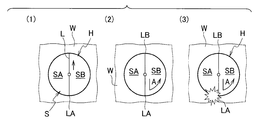
- FIG. 1A is a plan view of a plate-like workpiece that is subjected to laser cutting processing according to the prior art, and is a diagram illustrating a manner in which scrap pieces interfere with a laser processing head.
- FIG. 1B is a plan view of a plate-like workpiece that is subjected to laser cutting according to an embodiment of the present invention, and illustrates a mode in which a scrap piece is cut along a contour line after being divided.
- FIG. 1C is a plan view of a plate-like workpiece that is subjected to laser cutting according to an embodiment of the present invention, and illustrates a manner in which the workpiece is cut into a rectangle.
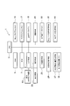
- FIG. 2 is a block diagram of a control device in the laser cutting machine.
- FIG. 1A is a plan view of a plate-like workpiece that is subjected to laser cutting processing according to the prior art, and is a diagram illustrating a manner in which scrap pieces interfere with a laser processing head.
- FIG. 1B is a plan
- FIG. 3 is an example of a display image on the display, and is a diagram for explaining a process of arranging a cutting line in a hole.
- FIG. 4A is an example of a display image on the display and is a diagram for explaining a case where 90 ° is input as an angle.
- FIG. 4B is an example of a display image on the display for explaining a case where 0 ° is input as an angle.
- FIG. 4C is an example of a display image on the display for explaining a case where 0 ° is input as an angle.
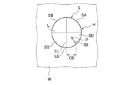
- FIG. 5A is a plan view of a plate-like workpiece that is subjected to laser cutting according to the present embodiment, and is a diagram illustrating a relationship between a piercing position that is a start position of laser cutting and a rectangular outline.
- FIG. 5B is a plan view of a plate-like workpiece that is subjected to laser cutting according to the present embodiment, and is a diagram illustrating a relationship between a piercing position that is a start position of laser cutting and a circular contour line.
- FIG. 6 is a block diagram of an automatic programming device.
- scrap piece SB cut and separated from the workpiece W has already been dropped and discharged, but sometimes, the scrap piece SB is caught by the scrap piece SB and the one end LA side protrudes from the upper surface of the workpiece W.
- laser cutting is performed along the contour line of the hole H, and when the laser processing head approaches the one end LA, the scrap piece SB Laser cutting head may interfere with laser cutting.
- laser cutting of the workpiece W is performed as shown in FIG. 1B. That is, the dividing line L is processed to divide the scrap S into scrap pieces SA and SB. Then, as shown in (2) of FIG. 1B, piercing P is performed in the scrap piece SB, and laser cutting is performed from the piercing position in the direction of the outline of the hole H as indicated by an arrow A, And laser cutting is performed along the contour line from the intersection C with the contour line.
- the scrap piece SB is placed on the workpiece W between one end LA of the dividing line L and the intersection position C. Connected. Thereafter, when laser cutting along the contour line of the hole H reaches the one end LA from the other end LB, the scrap piece SA is cut and separated from the workpiece W. However, the scrap piece SB is in a state of being connected to the workpiece W between the one end LA and the intersection position C. Therefore, one end side of the scrap piece SB does not protrude from the upper surface of the workpiece W. Therefore, when the scrap piece SA is cut and separated, the scrap piece SB and the laser processing head do not interfere with each other. After that, the scrap piece SB is cut and separated from the workpiece W by performing laser cutting processing from the one end LA of the dividing line L to the intersection position C.
- FIG. 1C when laser cutting of a rectangular hole HA is performed, laser cutting of a plurality of dividing lines L1 and L2 is performed, piercing P is performed in the scrap piece SC, and the hole HA is cut from this piercing position.
- the case where laser cutting is performed is shown.
- the scrap pieces SA are first cut and separated from the workpiece W, and then sequentially cut and separated from the scrap pieces SB and SC.
- the piece SC is finally cut and separated from the workpiece W.
- FIG. 1C when the scrap piece SA is pierced and laser cut, the scrap piece SA is finally cut and separated from the workpiece W.
- the scrap piece SB is pierced and subjected to laser cutting, the scrap piece SB is finally cut and separated from the workpiece W.
- scrap piece SB is sequentially cut and separated from the scrap pieces SA on the rear side of the laser processing head in the traveling direction along the outline of the hole, and laser cutting is performed by piercing.
- the scrap piece SB that has started processing is finally cut and separated.
- a laser cutting apparatus for performing laser cutting processing of various shapes on a plate-shaped workpiece, for example, a processing pallet or work table provided with a skid (the processing pallet also supports the workpiece). Therefore, it is provided with a laser processing head (not shown) that is relatively movable in the X, Y, and Z axis directions with respect to a plate-like work on the work table). Further, the laser cutting processing apparatus includes a control device 1 (see FIG. 2) that controls the operation of the laser processing head with respect to the workpiece.
- the control device 1 can be a general-purpose or dedicated computer, and includes a CPU 3, a RAM 5, a ROM 7, an input unit 9, and a display unit 11.
- the input means 9 is connected to an automatic programming device 13 that supplies (sends) a machining program to the control device 1.
- the machining program (NC data) generated in the automatic programming device 13 can be supplied to the control device 1 via an appropriate storage medium.
- a machining program memory 15 for storing a machining program generated in the automatic programming device is provided in the control device 1.
- the control device 1 stores a subprogram for performing laser cutting processing for cutting and separating the hole H to be processed into the workpiece W and the large scrap S in the hole H into a plurality of small scrap pieces SA and SB.
- a program memory (NC data memory) 17 is provided.
- control device 1 is provided with a graphic data memory 19.
- the graphic data memory 19 stores the shape data of the workpiece (product) W to be laser-cut and the position and shape data of the holes H arranged in the workpiece W.
- the graphic data stored in the graphic data memory 19 is calculated by the calculation means 21 that performs various calculations, and the graphic based on the graphic data is displayed on the display screen 23 in the display means 11.
- control device 1 is connected with a hole selecting means 25 for selecting a hole H included in the work (product) W displayed on the display screen 23.
- the hole selection means 25 is constituted by, for example, a mouse or the like that operates a cursor 27 (see FIG. 3) displayed on the display screen 23.
- the hole H is selected by placing the cursor 27 on the hole H on the display screen 23 and clicking.
- the control device 1 is provided with a dividing line arrangement means 29 connected thereto.
- the dividing line arranging means 29 has a function of arranging a linear scrap dividing line 31 (see FIG. 3) displayed on the display screen 23 in the selected hole H, and the hole selecting means 25 and a common mouse.
- positioning means 29 it can also be set as the structure which selects the hole H by contacting the display screen 23, and arrange
- the scrap dividing line 31 is displayed on the display screen 23 as a vertical straight line as shown in FIGS. 3 and 4A when an angle of 90 ° is input from the input means 9.
- 0 ° is input as the angle
- it is displayed as a horizontal straight line as shown in FIGS. 4B and 4C.
- the angle of the scrap dividing line 31 is input, for example, + 45 °
- it is displayed in a state inclined 45 ° counterclockwise from the horizontal state, and conversely, if it is input ⁇ 45 °, it is clockwise from the horizontal state.
- the dividing line arranging means 29 aligns the cursor 27 with the scrap dividing line 31 displayed on the display screen 23, and moves the cursor 27 in the horizontal direction or the vertical direction on the display screen 23, thereby the scrap dividing line 31. It has a function to move up, down, left and right. Then, the cursor 27 is placed at a position where the hole H where the scrap dividing line 31 is to be placed and the scrap dividing line 31 intersect (see (1) in FIG. 4A, (2) in FIG. 4B, (1) in FIG. 4C), When clicked, the hole H is selected, and the dividing line L is arranged in the hole H as shown in (2) of FIG. 4A, (3) of FIG. 4B, and (2) of FIG. 4C. . In this case, both ends of the dividing line L are connected to the outline of the hole H.
- the number of dividing lines L arranged in the hole H can be set to a desired number corresponding to the size of the scrap pieces SA and SB to be divided.
- the inclination angle of the dividing line L can be set to a desired inclination angle. That is, the large scrap S in the hole H can be divided into a plurality of desired small scrap pieces SA and SB.
- the dividing lines L are arranged so as not to generate a region surrounded by the plurality of dividing lines L.
- the scrap dividing line 31 in the hole H, it can arrange
- control device 1 is provided with a dividing line data memory 33.
- the dividing line data memory 33 stores the position data of the selected hole H and the shape data of the hole H in the work W, and stores arrangement data of an appropriate number of dividing lines L arranged in the hole H.
- control device 1 is provided with machining head operation control means 35.
- This machining head operation control means 35 performs X-, Y-, and Z-axis directions of a laser machining head (not shown) according to a machining program stored in the machining program memory 15 in order to perform laser cutting of the workpiece W and the hole H. It has a function to control the operation of the.
- control device 1 is provided with processing start position setting means 37 for starting laser cutting along the contour line of the hole H after performing laser cutting processing of the dividing line L in the hole H. Yes.
- the means for setting the processing start position may be configured to click the mouse after moving the cursor 27 into the desired scrap piece SA, SB. In this case, it is possible to arrange the processing start position in the strap pieces SA and SB at the desired positions regardless of the cutting order of the dividing lines L arranged in the holes H. Therefore, the machining start position may be far away from the position of the dividing line L where the last cutting process is performed, which is not desirable for improving efficiency.
- the machining start position setting unit 37 includes a machining start position memory 39.
- the machining start position memory 39 as shown in FIG. 5, when the laser cutting of the dividing line L in the hole H is performed, the hole H to the machining end LE of the dividing line LL to be cut last.
- the circumferential distance CD and the inner distance ID from the contour line of the hole H are set and stored. Therefore, when the dividing line LL to be cut last is determined, the processing start position, that is, the piercing processing position P can be set immediately.
- the control device 1 is provided with NC data generating means 41.
- the NC data generating means 41 has a function of generating NC data for performing laser cutting along the contour lines of the plurality of dividing lines L and the holes H arranged in the holes H. That is, the NC data generating means 41 has the hole H position data, shape data and arrangement data of the plurality of dividing lines L stored in the dividing line data memory 33 and the machining start position stored in the machining start position memory 39.
- the processing head operation control means 35 Based on the data of (piercing processing position P), in order to perform laser cutting processing along the plurality of dividing lines L arranged in the hole H and the contour line of the hole H, the processing head operation control means 35. It has a function of generating NC data (machining program) that can be executed by
- the NC data (machining program) generated by the NC data generating means 41 is stored in the subprogram memory 17 and is executed at the time of laser cutting processing of the corresponding hole H.
- the control device 1 when a machining program generated in the automatic programming device 13 is input to the control device 1, the machining program is stored in the machining program memory 15.
- the shape data of the workpiece (product) W is input simultaneously with the machining program, the shape data is stored in the graphic data memory 19.
- the control device 1 includes program analysis means (not shown). Then, the machining program can be analyzed by the program analysis means, and the shape data of the workpiece W can be stored in the graphic data memory 19.
- the shape of the workpiece W is displayed on the display screen 23 of the display means 11 based on the shape data stored in the graphic data memory 19, and the cursor 27 and the scrap dividing line 31 are displayed on the display screen 23. Then, as shown in FIG. 3, the cursor 27 is aligned with the scrap dividing line 31 and moved to the position of the desired hole H in the workpiece W. Then, the scrap dividing line 31 is arranged at a desired hole H position, and the cursor 27 is set at the intersection position of the outline of the hole H and the scrap dividing line 31 ((1) in FIG. 4A, FIG. 4B). (2) of FIG. 4C (see (1) of FIG. 4C), when clicked, the hole H is selected and the dividing line L is arranged in the hole H ((2) of FIG. 4A, ( 3), see (2) of FIG. 4C).
- FIG. 4B shows an example in which the scrap dividing line 31 that is 90 ° in FIG. 4A is changed to 0 °.
- a plurality of dividing lines L are arranged in the selected hole H.
- a plurality of dividing lines L are arranged in each hole H by performing the same operation on each hole H in the workpiece W.
- the order of laser cutting processing of the dividing lines L arranged in the holes H is set in advance in the order of arrangement of the dividing lines L with respect to the holes H. Accordingly, the piercing processing position P is set corresponding to the dividing line L arranged last.
- the position data, the shape data, the arrangement data of the dividing line L, and the last dividing line L are set for each hole H.
- the position data of the piercing position P is stored in the dividing line data memory 33 for each hole H.
- the laser cutting processing of each dividing line L in each hole H and the laser along the contour line of each hole H are performed.
- NC data (machining program) for cutting is generated by the NC data generating means 41.
- the generated NC data is stored in a subprogram memory (NC data memory) 17.
- a machining program for performing laser machining on the workpiece W is stored in the machining program memory 15, and the large scrap S in each hole H in the workpiece W is divided into a plurality of small scrap pieces SA and SB.
- the laser is controlled under the control of the machining head operation control means 35. The operation of the machining head is controlled, and the workpiece W is laser cut.
- the scrap in each hole H of the workpiece W is divided into small scrap pieces by an appropriate number of dividing lines L.
- laser cutting is performed from the piercing position P in the scrap piece to be dropped last. Therefore, when each scrap piece is cut and separated from the workpiece W in each hole H, it is sequentially cut and separated on the rear side in the traveling direction of the laser processing head. Therefore, even when a part of the scrap piece after being cut and separated protrudes from the upper surface of the workpiece W, the scrap piece from which the part protrudes does not interfere with the laser processing head. . That is, the laser cutting process does not stop due to the interference between the scrap piece and the laser processing head.
- the control device 1 generates NC data (processing program) for performing laser cutting processing of the dividing line L in the hole H in the workpiece W and laser cutting processing along the contour line of the hole H.
- the NC data can be generated by the automatic programming device 13. That is, the automatic programming device 13 is composed of a computer, like the control device 1. And the component which has the same function as the component in the said control apparatus 1 is provided.
- the overlapping description is abbreviate
- the automatic programming device 13 includes a product shape data memory 43 that stores data on the outer shape of the workpiece (product) W, and stores data on the holes H of various shape dimensions.
- a hole shape data memory 45 is provided.
- the automatic programming device 13 is provided with component placement means 47 for placing the product W on a plate-like material and placing various holes H in the product W.
- the component arranging means 47 is constituted by a mouse, for example, and operates the cursor 27 displayed on the display screen 23 in the display means 11 to arrange the product W and the hole H.
- the shape of the plate material is displayed on the display screen 23.
- the product (work) W is displayed on the display screen 23 based on the product shape data stored in the product shape data memory 43.
- the component placement means 47 By operating the component placement means 47 to align the cursor 27 with the displayed product W, and moving the cursor 27 to the inside of the plate material displayed on the display screen 23, the product W for the plate material is displayed. Is arranged. Thereafter, various holes H are displayed on the display screen 23 based on the data stored in the hole shape data memory 45. Then, by operating the component arranging means 47, the cursor 27 is placed on the hole H on the display screen 23, and the hole H is moved into the product W, whereby the hole H is arranged with respect to the product W.
- this arrangement data is stored in the component arrangement data memory 49.
- the position data of the product W and the shape data of the product with respect to the plate material are stored in the component arrangement data memory 49.
- the part arrangement data memory 49 stores the position data of each hole H and the shape data of each hole H with respect to the product W. Based on the data stored in the component arrangement data memory 49, the product W and the hole H are displayed on the display screen 23 as shown in FIG.
- the NC data generating means 41 provided in the automatic programming device 13 can generate a machining program for performing laser cutting along the dividing line L in each hole H and the contour line of each hole H. Can be stored.
- a machining program for dividing the large scrap S in the hole H provided in the workpiece (product) W into a plurality of small scraps SA and SB can be generated also in the control device 1. It can also be generated by the automatic programming device 13.
- a machining program for performing laser machining of the workpiece W and a machining program stored in the subprogram memory 17 are supplied as a series of machining programs. It is also possible.
- a laser cutting processing method and apparatus and an automatic programming device in which scrap pieces generated by laser cutting processing do not interfere with a laser processing head.
Landscapes
- Physics & Mathematics (AREA)
- Optics & Photonics (AREA)
- Engineering & Computer Science (AREA)
- Plasma & Fusion (AREA)
- Mechanical Engineering (AREA)
- Laser Beam Processing (AREA)
Abstract
板状のワークに穴のレーザ切断加工を行うレーザ切断加工方法であって、穴Hのレーザ切断加工を行うことにより生じる大きなスクラップSを複数の小さなスクラップ片SA,SBに分割するための適数本のスクラップ分割線Lを、前記ワークにおいて前記穴Hに相当する穴相当領域内にレーザ切断加工を行った後、最後に落下すべきスクラップ片SD内から前記穴Hの輪郭線方向へのレーザ切断加工を開始し、かつ前記穴Hの輪郭線に沿ってレーザ切断加工を行う。
Description
本発明は、板状のワーク(製品)に適宜形状の穴の加工を行うレーザ切断加工方法及び装置並びにレーザ切断加工装置を制御するためのNCデータを生成する自動プログラミング装置に関する。さらに詳細には、レーザ切断加工装置によるワークの穴加工時に、レーザ加工穴内に生じる大きなスクラップを小さな複数のスクラップ片に分割し、スクラップ片とレーザ加工ヘッドとの干渉を生じることなく穴加工を行うことのできるレーザ切断加工方法及び装置並びに自動プログラミング装置に関する。
板状のワークに対して比較的大きな穴のレーザ切断加工を行うと、上記穴内に大きなスクラップが生じることになる。このスクラップが、ワークを支持するワークテーブルに開閉自在に備えられたワークシュータよりも大きい場合には、スクラップの排出が難しくなる。また、ワークテーブルの一例として、ワークを支持するスキッドを適宜間隔に備えた加工テーブルによりワークを水平に支持して、ワークに穴のレーザ切断加工を行うと、生じたスクラップが前記スキッド上に残ることになる。そこで、前記スクラップをワークシュータから排出口内へスクラップを落下するために、又は加工テーブルにおけるスキッドの間隔内にスクラップを落下するために、前記穴内のスクラップを、小さな複数のスクラップ片に分割切断することが行われている(例えば特許文献1参照)。
前記特許文献1に記載の構成によれば、穴内に生じる大きなスクラップを小さなスクラップ片に分割するものであるから、スクラップ片の排出は比較的容易に行われ得る。しかし、穴内のスクラップを複数の小さなスクラップ片に分割切断して排出するとき、排出すべきスクラップ片に、例えば傾斜等が生じて穴内に引っ掛かりを生じると、スクラップ片の一部がワーク上面から突出することがある。このように、スクラップ片の一部がワーク上面から突出すると、この突出部とレーザ加工ヘッドとが干渉することがあり、連続してのレーザ切断加工が困難になることがある。
本発明は、前述のごとき問題に鑑みてなされたもので、板状のワークに穴のレーザ切断加工を行うレーザ切断加工方法であって、穴のレーザ切断加工を行うことにより生じる大きなスクラップを複数の小さなスクラップ片に分割するための適数本のスクラップ分割線を、前記ワークにおいて前記穴に相当する穴相当領域内にレーザ切断加工を行った後、最後に落下すべきスクラップ片内から前記穴の輪郭線方向へのレーザ切断加工を開始し、かつ前記穴の輪郭線に沿ってレーザ切断加工を行うことを特徴とするものである。
また、前記レーザ切断加工方法において、前記スクラップ分割線の両端は前記穴の輪郭線に達しており、かつ前記各スクラップ片は前記穴の輪郭線に接続した状態に各スクラップ分割線のレーザ切断加工を行うことを特徴とするものである。
また、ワークテーブル上の板状のワークに対してX,Y,Z軸方向へ相対的に移動自在なレーザ加工ヘッドを備えたレーザ切断加工装置であって、前記レーザ加工ヘッドの動作を制御する制御装置を備え、この制御装置は、板状の素材からワークの切断加工を行う図形を格納した図形データメモリと、上記図形データメモリに格納された図形データの図形を表示する表示手段と、この図形が表示された表示画面上において図形内の穴を選択する穴選択手段と、当該穴選択手段によって選択された穴内に適数本のスクラップ分割線を配置する分割線配置手段と、分割されたスクラップ片内にレーザ切断加工開始位置を設定する加工開始位置設定手段と、選択された前記穴の位置データ及び形状データと前記穴内に配置された分割線配置データ及びレーザ切断加工開始位置データに基いて、選択された前記穴内のスクラップの分割を行うレーザ切断加工及び選択された穴の輪郭線に沿ってのレーザ切断加工を行うためのNCデータを生成するNCデータ生成手段と、生成された上記NCデータを格納するNCデータメモリと、を備えていることを特徴とするものである。
また、前記レーザ切断加工装置において、前記加工開始位置設定手段は、最後に配置されたスクラップ分割線から穴の周方向に予め設定され距離だけ離れた位置であって、かつ前記穴の輪郭線の内側へ所定距離だけ離れた位置を加工開始位置として予め格納した加工開始位置メモリを備えていることを特徴とするものである。
また、ワークテーブル上の板状の素材に対してX,Y,Z軸方向へ相対的に移動自在なレーザ加工ヘッドを備えたレーザ切断加工装置の制御装置に対して、前記板状素材のレーザ切断加工を行う加工プログラムを提供する自動プログラミング装置であって、製品形状データに基いて板状素材上に製品形状を配置する部品配置手段と、当該部品配置手段によって配置された板状素材上の製品及び板状素材を表示する表示手段と、板状素材が表示された表示画面上において、表示された製品内の穴を選択する穴選択手段と、当該穴選択手段によって選択された穴内に適数本のスクラップ分割線を配置する分割線配置手段と、分割されたスクラップ片内にレーザ切断加工開始位置を設定する加工開始位置設定手段と、選択された前記穴の位置データ及び形状データと前記穴内に配置された分割線配置データ及びレーザ切断加工開始位置データに基いて選択された穴内のスクラップの分割を行うレーザ切断加工及び選択された穴の輪郭線に沿ってのレーザ切断加工を行うためのNCデータ及び前記素材内の製品のレーザ切断加工を行うためのNCデータを生成するNCデータ生成手段と、生成されたNCデータを格納するNCデータメモリと、を備えていることを特徴とするものである。
また、前記自動プログラミング装置において、前記加工開始位置設定手段は、最後に配置されたスクラップ分割線から穴の周方向に予め設定された距離だけ離れた位置であって、かつ前記穴の輪郭線の内側へ所定距離だけ離れた位置を加工開始位置として予め格納した加工開始位置メモリを備えていることを特徴とするものである。
本発明によれば、ワークに穴のレーザ切断加工を行うことにより生じる穴内のスクラップは小さなスクラップ片に分割されるので、スクラップ片の落下排出を容易に行うことができる。そして、スクラップ片に引っ掛かりが生じたような場合には、レーザ加工ヘッドの通過後に生じるものである。すなわち、レーザ加工ヘッドは、切断分離されたスクラップ片から離反する方向へレーザ切断加工を行うものであるから、スクラップ片の一部がワーク上面から突出したような場合であっても、レーザ加工ヘッドがスクラップ片と干渉するようなことはないものである。
本発明の幾つかの例示的な実施形態を添付の図面を参照して以下に説明する。図面は必ずしも正確な縮尺により示されておらず、従って相互の寸法関係は図示されたものに限られないことに、特に注意を要する。
理解を容易にするために、先ず、スクラップ片とレーザ加工ヘッドとが干渉する原因について説明する。
図1Aに示すように、板状のワーク(製品)Wに適宜形状の穴Hのレーザ切断加工を行うと、この穴H内には穴Hの形状に対応した大きなスクラップSが生じる。このスクラップSを複数のスクラップ片SA,SBに分割するために、穴Hのレーザ切断加工前に、前記穴Hの位置に相当する穴相当領域内に適数本の分割線Lをレーザ加工する。そして、前記分割線Lの一端LAから矢印Aで示すように、穴Hの輪郭線に沿ってレーザ切断加工を行い、前記分割線Lの他端LBに達すると、スクラップ片SBはワークWから切断分離される。その後、前記矢印A方向へのレーザ切断加工が進行し、前記他端LBから前記一端LAに達すると、穴Hの輪郭線に沿って一周のレーザ切断加工が行われることとなり、スクラップ片SAもワークWから切断分離されることになる。
ワークWから切断分離されたスクラップ片SBが既に落下排出されていればよいが、ときとして、スクラップ片SBに引っ掛かり、前記一端LA側がワークW上面から突出することがある。このように、先に切断したスクラップ片SBの一部がワーク上面から突出すると、穴Hの輪郭線に沿ってレーザ切断加工を行って、レーザ加工ヘッドが前記一端LAに近接すると、スクラップ片SBとレーザ加工ヘッドとが干渉して、レーザ切断加工が停止することがある。
そこで、本実施形態においては、図1Bに示すようにワークWのレーザ切断加工を行う。すなわち、スクラップSをスクラップ片SA,SBに分割すべく分割線Lの加工を行う。そして、図1Bの(2)に示すように、スクラップ片SB内にピアス加工Pを行い、このピアス加工位置から、矢印Aで示すように、穴Hの輪郭線方向へレーザ切断加工を行い、かつ輪郭線との交差位置Cから輪郭線に沿ってレーザ切断加工を行う。
この場合、レーザ切断加工が進行し、分割線Lの他端LBにレーザ切断加工が達したとき、スクラップ片SBは、分割線Lの一端LAと前記交差位置Cとの間において、ワークWに接続した状態にある。その後、穴Hの輪郭線に沿ってのレーザ切断加工が、前記他端LBから一端LAに達すると、スクラップ片SAはワークWから切断分離される。しかし、スクラップ片SBは、前記一端LAと交差位置Cとの間においてワークWと接続した状態にある。したがって、スクラップ片SBの一端側はワークWの上面に突出するようなことはない。よって、スクラップ片SAの切断分離時に、スクラップ片SBとレーザ加工ヘッドが干渉することはない。その後、分割線Lの一端LAから前記交差位置Cにレーザ切断加工が行われることによって、スクラップ片SBはワークWから切断分離される。
図1Cは、矩形状の穴HAのレーザ切断加工を行う場合、複数の分割線L1,L2のレーザ切断加工を行い、スクラップ片SC内にピアス加工Pを行い、このピアス加工位置から穴HAのレーザ切断加工を行う場合を示す。この場合、穴HAの輪郭線に沿ってレーザ切断加工が矢印A方向に進行すると、先ず、スクラップ片SAがワークWから切断分離され、次に、スクラップ片SB,SCと順次切断分離され、スクラップ片SCがワークWから最後に切断分離される。ところで、図1Cにおいて、スクラップ片SAにピアス加工を行ってレーザ切断加工を行うと、スクラップ片SAがワークWから最後に切断分離されることになる。同様に、スクラップ片SBにピアス加工を行ってレーザ切断加工を行うと、スクラップ片SBがワークWから最後に切断分離されることになる。
既に理解されるように、ワークWに適宜形状の穴のレーザ切断加工を行うとき、穴の加工によって生じる大きなスクラップSを複数の小さなスクラップ片SA,SBに切断分割する場合、ワークの穴相当領域内に適数本の分割線Lをレーザ切断加工する。この際、上記各分割線Lの両端部は穴の輪郭線に接するように、又は重なるように、かつ、各スクラップ片SA,SBは、穴の輪郭線に接続した状態に加工される。換言すれば、穴内に複数の分割線Lをレーザ加工するとき、分割線Lのみによって囲まれた領域を生じないように分割線Lを配置する。
そして、最後に落下すべきスクラップ片SB内にピアス加工Pを行ってレーザ切断加工を開始し、穴の輪郭線に沿ってレーザ切断加工を行うことにより、複数の小さなスクラップ片SA,SBを穴内から切断分離することができる。このようにスクラップ片SA,SBの切断加工を行うことにより、穴の輪郭線に沿ってのレーザ加工ヘッドの進行方向の後側のスクラップ片SAから順次切断分離され、ピアス加工を行ってレーザ切断加工を開始したスクラップ片SBが最後に切断分離されることになる。
したがって、切断分離された後のスクラップ片SAの一部がワークWの上面に突出したような場合であっても、当該突出部とレーザ加工ヘッドとが干渉するようなことはない。
ところで、板状のワークに種々の形状のレーザ切断加工を行うレーザ切断加工装置は、既に知られているように、例えばスキッドを備えた加工パレットやワークテーブル(前記加工パレットもワークを支持するものであるからワークテーブルに相当する)上の板状のワークに対してX,Y,Z軸方向へ相対的に移動自在なレーザ加工ヘッド(図示省略)を備えている。また、レーザ切断加工装置は、ワークに対する前記レーザ加工ヘッドの動作を制御する制御装置1(図2参照)を備えている。
前記制御装置1には汎用のまたは専用のコンピュータを利用することができ、CPU3、RAM5、ROM7、入力手段9、表示手段11を備えている。そして、前記入力手段9には、当該制御装置1に対して加工プログラムを供給(送信)する自動プログラミング装置13が接続してある。なお、前記自動プログラミング装置13において生成された加工プログラム(NCデータ)を、制御装置1に対して供給する構成としては、適宜の記憶媒体を介して供給することも可能である。前記自動プログラミング装置において生成された加工プログラムを格納する加工プログラムメモリ15が前記制御装置1に備えられている。また、前記制御装置1には、ワークWに加工する穴H及び穴H内の大きなスクラップSを複数の小さなスクラップ片SA,SBに切断分離するためのレーザ切断加工を行うサブプログラムを格納するサブプログラムメモリ(NCデータメモリ)17が備えられている。
さらに、制御装置1には図形データメモリ19が備えられている。この図形データメモリ19は、レーザ切断加工を行うワーク(製品)Wの形状データ及び上記ワークW内に配置される穴Hの位置、形状データを格納する。そして、この図形データメモリ19に格納された図形データは、各種の演算を行う演算手段21によって演算され、上記図形データに基づく図形は表示手段11における表示画面23に表示される。
また、前記制御装置1には、前記表示画面23に表示されたワーク(製品)W内に含まれる穴Hを選択する穴選択手段25が接続してある。この穴選択手段25は、表示画面23に表示されたカーソル27(図3参照)を操作する、例えばマウス等によって構成してある。そして穴Hの選択を行うときには、表示画面23上の穴Hに前記カーソル27を合せてクリックすることにより穴Hを選択する機能を有する。さらに、前記制御装置1には、分割線配置手段29が接続して備えられている。この分割線配置手段29は、前記表示画面23に表示された直線状のスクラップ分割線31(図3参照)を選択された穴H内に配置する機能を有するものであって、前記穴選択手段25と共通のマウス等によって構成してある。
なお、前記穴選択手段25、分割線配置手段29の構成としては、表示画面23に接触することによって穴Hを選択することや、スクラップ分割線31を配置する構成とすることも可能である。すなわち、マウス等に代えて、例えばタッチペン等とすることも可能である。
前記スクラップ分割線31は、入力手段9から角度として90°を入力すると、図3,図4Aに示されるように垂直な直線として表示画面23に表示される。そして、角度として0°を入力すると、図4B,4Cに示されるように、水平な直線として表示される。また、スクラップ分割線31の角度として、例えば+45°と入力すると、水平状態から反時計回り方向に45°傾斜した状態に表示され、逆に、-45°と入力すると、水平状態から時計回り方向に45°傾斜した状態に表示される。すなわち、スクラップ分割線31の傾斜角度は、ワークW内の穴Hの形状、寸法や傾斜に対応して所望の傾斜角とすることができる。
前記分割線配置手段29は、表示画面23に表示されたスクラップ分割線31にカーソル27を合せて、表示画面23上においてカーソル27を左右方向又は上下方向に移動することにより、前記スクラップ分割線31を上下左右方向へ移動する機能を備えている。そして、スクラップ分割線31を配置したい穴Hとスクラップ分割線31とが交差した位置にカーソル27を合せ(図4Aの(1),図4Bの(2),図4Cの(1)参照)、クリックすると、穴Hが選択されると共に、図4Aの(2),図4Bの(3),図4Cの(2)に示すように、穴H内に分割線Lが配置されることになる。この場合、分割線Lの両端は、穴Hの輪郭線に接続した状態にある。
穴H内に配置する分割線Lの本数は、分割するスクラップ片SA,SBの大きさに対応して所望の本数とすることができる。また、分割線Lの傾斜角も所望の傾斜角とすることができる。すなわち、穴H内の大きなスクラップSを、所望の小さい複数のスクラップ片SA,SBに分割することができる。なお、穴H内に複数本の分割線Lを配置するに際しては、複数本の分割線Lによって囲繞された領域が生じないように配置する。上述のように複数本の分割線Lを配置することにより、穴H内において小さなスクラップ片SA,SBに切断分離される各スクラップ片SA,SBは、穴Hの輪郭線に接続した状態に分割される。
なお、穴H内にスクラップ分割線31を配置する機能としては、次のごとき機能を備えることによっても配置可能である。すなわち、穴H内の輪郭線の適宜位置にカーソル27を合わせてクリックすると、カーソル27を合わせた輪郭線の位置から穴H内にスクラップ分割線31を表示する機能を備える。この場合、前記輪郭線が直線の場合には、当該輪郭線に対して垂直に、前記輪郭線が曲線の場合には、当該輪郭線の接線に対して垂直にスクラップ分割線31を表示する機能を備えることが望ましい。
また、前記制御装置1には、分割線データメモリ33が備えられている。この分割線データメモリ33は、ワークW内の選択された穴Hの位置データ及び穴Hの形状データを格納すると共に、当該穴Hに配置された適数の分割線Lの配置データが格納される。
さらに、前記制御装置1には、加工ヘッド動作制御手段35が備えられている。この加工ヘッド動作制御手段35は、ワークW、穴Hのレーザ切断加工を行うために、前記加工プログラムメモリ15に格納された加工プログラムに従ってレーザ加工ヘッド(図示省略)のX,Y,Z軸方向への動作を制御する機能を有するものである。
また、前記制御装置1には、穴H内に分割線Lのレーザ切断加工を行った後に、穴Hの輪郭線に沿ってのレーザ切断加工を開始する加工開始位置設定手段37が備えられている。上記加工開始位置を設定する手段としては、所望のスクラップ片SA,SB内へカーソル27を移動した後にマウスをクリックする構成とすることも可能である。この場合、穴H内に配置される分割線Lの切断順に拘わりなく所望位置のストラップ片SA,SB内に加工開始位置を配置することが可能である。したがって、最後の切断加工を行った分割線Lの位置から加工開始位置が大きく離れることがあり、能率向上を図る上において望ましいものではない。
そこで、本実施形態においては、加工開始位置設定手段37に加工開始位置メモリ39を備えている。この加工開始位置メモリ39には、図5に示すように、穴H内の分割線Lのレーザ切断加工を行うとき、最後に切断加工を行うことになる分割線LLの加工終端LEから穴Hの周方向の距離CD及び穴Hの輪郭線から内方の距離IDにそれぞれを設定して格納してある。したがって、最後に切断加工される分割線LLが決定されると、加工開始位置すなわちピアシング加工位置Pは直ちに設定可能である。
また、前記制御装置1には、NCデータ生成手段41が備えられている。このNCデータ生成手段41は、穴H内に配置された複数の分割線L及び穴Hの輪郭線に沿ってのレーザ切断加工を行うNCデータを生成する機能を有するものである。すなわち、NCデータ生成手段41は、前記分割線データメモリ33に格納された穴Hの位置データ、形状データ及び複数の分割線Lの配置データ並びに前記加工開始位置メモリ39に格納された加工開始位置(ピアシング加工位置P)のデータに基いて、前記穴H内に配置された複数の分割線L及び穴Hの輪郭線に沿ってのレーザ切断加工を行うために、前記加工ヘッド動作制御手段35で実行可能なNCデータ(加工プログラム)を生成する機能を有するものである。
なお、穴H内の分割線L及び穴Hの輪郭線のレーザ切断加工を行うための加工条件は、前記加工プログラムメモリ15に格納される加工プログラムと同一の加工条件である。そして、前記NCデータ生成手段41によって生成されたNCデータ(加工プログラム)は、前記サブプログラムメモリ17に格納され、該当する穴Hのレーザ切断加工時に実行される。
以上のごとき構成において、自動プログラミング装置13において生成された加工プログラムが制御装置1に入力されると、当該加工プログラムは加工プログラムメモリ15に格納される。また、前記加工プログラムと同時にワーク(製品)Wの形状データが入力されると、この形状データは図形データメモリ19に格納される。なお、上記図形データメモリ19にワークWの形状データを格納する構成としては、制御装置1にプログラム解析手段(図示省略)を備える。そして、このプログラム解析手段によって加工プログラムの解析を行って、ワークWの形状データを図形データメモリ19に格納することも可能である。
前記図形データメモリ19に格納された形状データに基いてワークWの形状を表示手段11における表示画面23に表示すると共に、上記表示画面23にカーソル27及びスクラップ分割線31を表示する。そして、図3に示すように、上記スクラップ分割線31にカーソル27を合せて、ワークW内の所望の穴Hの位置へ移動する。そして、所望の穴Hの位置へ前記スクラップ分割線31を配置すると共に、当該穴Hの輪郭線と前記スクラップ分割線31との交差位置にカーソル27を合せ(図4Aの(1),図4Bの(2),図4Cの(1)参照)、クリックすると、当該穴Hが選択されると共に、当該穴H内に分割線Lが配置される(図4Aの(2),図4Bの(3),図4Cの(2)参照)。なお、図4Bは、図4Aにおいて90°であったスクラップ分割線31を0°に変更した場合でもって例示してある。
前述のごとき操作を複数回及びスクラップ分割線31の角度を変更しての操作を複数回行うことにより、選択された穴H内に複数本の分割線Lが配置されることになる。なお、ワークW内の各穴Hに対して同様の操作を行うことにより、各穴H内にそれぞれ複数の分割線Lが配置されることになる。そして、各穴H内に配置した各分割線Lのレーザ切断加工順は、各穴Hに対する各分割線Lの配置順に予め設定してある。したがって、最後に配置した分割線Lに対応してピアシング加工位置Pが設定されることになる。
前述のごとく、ワークWの各穴Hに対して分割線Lを配置すると、各穴Hの位置データ、形状データ、分割線Lの配置データ及び最後になった分割線Lに対応して設定されたピアシング加工位置Pの位置データが、各穴H毎に分割線データメモリ33に格納される。そして、上記分割線データメモリ33に格納された各穴Hのそれぞれに対応したデータに基いて、各穴H内の各分割線Lのレーザ切断加工及び各穴Hの輪郭線に沿ってのレーザ切断加工を行うNCデータ(加工プログラム)がNCデータ生成手段41によって生成される。そして、生成された上記NCデータはサブプログラムメモリ(NCデータメモリ)17に格納される。
上述のように、ワークWのレーザ加工を行うための加工プログラムが加工プログラムメモリ15に格納され、かつワークWにおける各穴H内の大きなスクラップSを複数の小さなスクラップ片SA,SBに分割するための複数本の分割線L及び各穴Hの輪郭線に沿ってのレーザ切断加工を行うための加工プログラムがサブプログラムメモリ17に格納されると、加工ヘッド動作制御手段35の制御の下にレーザ加工ヘッドの動作が制御されて、ワークWのレーザ切断加工が行われる。
この際、ワークWの各穴H内のスクラップは、適数本の分割線Lによって小さなスクラップ片に分割される。そして、各穴Hの輪郭線に沿ってレーザ切断加工を行うときは、最後に落下すべきスクラップ片内のピアシング加工位置Pからレーザ切断加工を行う。したがって、各スクラップ片を各穴H内においてワークWから切断分離するとき、レーザ加工ヘッドの進行方向の後側において順次切断分離される。よって、切断分離された後のスクラップ片の一部がワークWの上面から突出したような場合であっても、この一部が突出したスクラップ片とレーザ加工ヘッドとが干渉するようなことはない。すなわち、スクラップ片とレーザ加工ヘッドとの干渉によってレーザ切断加工が停止するようなことはない。
ところで、前記説明においては、ワークWにおける穴H内の分割線Lのレーザ切断加工及び穴Hの輪郭線に沿ってのレーザ切断加工を行うNCデータ(加工プログラム)を制御装置1において生成する旨の説明を行った。しかし、前記自動プログラミング装置13において前記NCデータを生成することも可能である。すなわち、前記自動プログラミング装置13は、前記制御装置1と同様にコンピュータから構成してある。そして、前記制御装置1における構成要素と同一機能を奏する構成要素を備えている。なお、同一機能を奏する構成要素には同一符号を付することとして重複した説明は省略する。
自動プログラミング装置13は、図6に示すように、前記ワーク(製品)Wの外形形状のデータを格納した製品形状データメモリ43を備えていると共に、各種の形状寸法の穴Hのデータを格納した穴形状データメモリ45を備えている。さらに、自動プログラミング装置13には、板状の素材上に前記製品Wを配置すると共に、当該製品Wに対して各種穴Hを配置する部品配置手段47を備えている。この部品配置手段47は、例えばマウスから構成してあって、表示手段11における表示画面23に表示されたカーソル27を操作して、製品W、穴Hの配置を行う。
すなわち、入力手段9から板状素材の形状寸法を入力すると、この板状素材の形状が表示画面23上に表示される。そして、製品形状データメモリ43に格納された製品形状データに基いて製品(ワーク)Wを表示画面23に表示する。この表示された製品Wに、部品配置手段47を操作してカーソル27を合せ、表示画面23に表示されている板状素材の内部へ上記カーソル27を移動することにより、板状素材に対する製品Wの配置が行われる。その後、穴形状データメモリ45に格納されているデータに基いて各種の穴Hを表示画面23に表示する。そして、部品配置手段47を操作し、表示画面23上の穴Hにカーソル27を合せ、この穴Hを製品W内へ移動することにより、製品Wに対する穴Hの配置が行われる。
上述のように、板状素材に対して製品Wを配置し、この製品Wに対して各穴Hを配置すると、この配置データが部品配置データメモリ49に格納される。すなわち、板状素材に対する製品Wの位置データ及び製品の形状データが部品配置データメモリ49に格納される。さらに、部品配置データメモリ49には、前記製品Wに対する各穴Hの位置データ及び各穴Hの形状データが格納される。そして、この部品配置データメモリ49に格納されたデータに基いて、図3に示すように、製品W及び穴Hが表示画面23に表示される。
上述のように、製品W及び穴Hが表示された表示画面23にスクラップ分割線31及びカーソル27を表示することにより、前述と同様の操作によって、製品W内の各穴H内にそれぞれ複数の分割線Lを配置することができる。したがって、自動プログラミング装置13に備えたNCデータ生成手段41によって、各穴H内の分割線L及び各穴Hの輪郭線に沿ってレーザ切断加工を行う加工プログラムを生成でき、サブプログラムメモリ17に格納することができる。
既に理解されるように、ワーク(製品)Wに備えた穴H内の大きなスクラップSを小さな複数のスクラップSA,SBに分割するための加工プログラムは、制御装置1においても生成することができ、また、自動プログラミング装置13においても生成することができる。
なお、自動プログラミング装置13から前記制御装置1へ加工プログラムを供給する場合、ワークWのレーザ加工を行う加工プログラムと、前記サブプログラムメモリ17に格納された加工プログラムとを一連の加工プログラムとして供給することも可能である。
レーザ切断加工に伴って生じるスクラップ片がレーザ加工ヘッドに干渉しないレーザ切断加工方法及び装置並びに自動プログラミング装置が提供される。
Claims (6)
- 板状のワークに穴のレーザ切断加工を行うレーザ切断加工方法であって、
穴のレーザ切断加工を行うことにより生じる大きなスクラップを複数の小さなスクラップ片に分割するための適数本のスクラップ分割線を、前記ワークにおいて前記穴に相当する穴相当領域内にレーザ切断加工を行い、
前記穴相当領域内にレーザ切断加工を行う段階に続いて、前記複数のスクラップ片から選択された最後に落下すべき一のスクラップ片内から前記穴の輪郭線方向へレーザ切断加工を行い、
前記穴の前記輪郭線方向へレーザ切断加工を行う段階に続いて、前記穴の輪郭線に沿ってレーザ切断加工を行う、
ことを含むレーザ切断加工方法。 - 請求項1に記載のレーザ切断加工方法であって、前記穴相当領域内にレーザ切断加工を行う段階において、前記スクラップ分割線の両端を前記穴の輪郭線に達さしめ、前記各スクラップ片は前記穴の輪郭線に接続した状態にする、レーザ切断加工方法。
- 板状のワークに穴のレーザ切断加工を行うレーザ切断加工装置であって、
前記ワークを載せるワークテーブルと、
前記ワークテーブル上の前記ワークに対してX,Y,Z軸方向へ相対的に移動自在なレーザ加工ヘッドと、
前記レーザ加工ヘッドの動作を制御する制御装置であって、
板状の素材からワークの切断加工を行う図形を格納した図形データメモリと、
前記図形データメモリに格納された図形データの図形を表示する表示手段と、
前記図形が表示された表示画面上において前記図形内の穴を選択する穴選択手段と、
前記穴選択手段によって選択された前記穴内に適数本のスクラップ分割線を配置する分割線配置手段と、
分割されたスクラップ片内にレーザ切断加工開始位置を設定する加工開始位置設定手段と、
選択された前記穴の位置データ及び形状データと前記穴内に配置された分割線配置データ及びレーザ切断加工開始位置データに基いて、選択された前記穴内のスクラップの分割を行うレーザ切断加工及び選択された穴の輪郭線に沿ってのレーザ切断加工を行うためのNCデータを生成するNCデータ生成手段と、
生成された上記NCデータを格納するNCデータメモリと、
を備えた制御装置と、
を備えたレーザ切断加工装置。 - 請求項3に記載のレーザ切断加工装置であって、前記加工開始位置設定手段は、前記複数本のスクラップ分割線から選択された最後に配置される一のスクラップ分割線から穴の周方向に予め設定された距離だけ離れた位置であって、かつ前記穴の輪郭線の内側へ所定距離だけ離れた位置を、加工開始位置として予め格納した加工開始位置メモリを備えている、レーザ切断加工装置。
- ワークテーブル上の板状の素材に対してX,Y,Z軸方向へ相対的に移動自在なレーザ加工ヘッドを備えたレーザ切断加工装置の制御装置に対して、前記板状素材のレーザ切断加工を行う加工プログラムを提供する自動プログラミング装置であって、
製品形状データに基いて板状素材上に製品形状を配置する部品配置手段と、
前記部品配置手段によって配置された前記板状素材上の製品及び前記板状素材を表示する表示手段と、
前記板状素材が表示された表示画面上において、表示された前記製品内の穴を選択する穴選択手段と、
当該穴選択手段によって選択された前記穴内に適数本のスクラップ分割線を配置する分割線配置手段と、
分割されたスクラップ片内にレーザ切断加工開始位置を設定する加工開始位置設定手段と、
選択された前記穴の位置データ及び形状データと前記穴内に配置された分割線配置データ及びレーザ切断加工開始位置データに基いて選択された前記穴内のスクラップの分割を行うレーザ切断加工及び選択された穴の輪郭線に沿ってのレーザ切断加工を行うためのNCデータ及び前記板状素材内の製品のレーザ切断加工を行うためのNCデータを生成するNCデータ生成手段と、
生成された前記NCデータを格納するNCデータメモリと、
を備えた自動プログラミング装置。 - 請求項5に記載の自動プログラミング装置であって、前記加工開始位置設定手段は、前記複数本のスクラップ分割線から選択された最後に配置される一のスクラップ分割線から穴の周方向に予め設定された距離だけ離れた位置であって、かつ前記穴の輪郭線の内側へ所定距離だけ離れた位置を、加工開始位置として予め格納した加工開始位置メモリを備えている、自動プログラミング装置。
Applications Claiming Priority (2)
| Application Number | Priority Date | Filing Date | Title |
|---|---|---|---|
| JP2013-244567 | 2013-11-27 | ||
| JP2013244567A JP6225001B2 (ja) | 2013-11-27 | 2013-11-27 | レーザ切断加工方法及び装置並びに自動プログラミング装置 |
Publications (1)
| Publication Number | Publication Date |
|---|---|
| WO2015080179A1 true WO2015080179A1 (ja) | 2015-06-04 |
Family
ID=53199118
Family Applications (1)
| Application Number | Title | Priority Date | Filing Date |
|---|---|---|---|
| PCT/JP2014/081311 Ceased WO2015080179A1 (ja) | 2013-11-27 | 2014-11-27 | レーザ切断加工方法及び装置並びに自動プログラミング装置 |
Country Status (2)
| Country | Link |
|---|---|
| JP (1) | JP6225001B2 (ja) |
| WO (1) | WO2015080179A1 (ja) |
Cited By (4)
| Publication number | Priority date | Publication date | Assignee | Title |
|---|---|---|---|---|
| DE102016220459B3 (de) | 2016-10-19 | 2018-03-29 | Trumpf Werkzeugmaschinen Gmbh + Co. Kg | Verfahren und Maschine zum schneidenden Bearbeiten eines Werkstücks |
| DE102018217200A1 (de) * | 2018-10-09 | 2020-04-09 | Trumpf Werkzeugmaschinen Gmbh + Co. Kg | Verfahren und Bearbeitungsmaschine zum Schneiden von Werkstücken sowie zugehöriges Computerprogrammprodukt |
| EP4252956A4 (en) * | 2020-11-27 | 2024-06-26 | Amada Co., Ltd. | LASER MACHINING METHOD, LASER MACHINING DEVICE AND MACHINING PROGRAM CREATION DEVICE |
| WO2025083114A1 (de) * | 2023-10-19 | 2025-04-24 | TRUMPF Werkzeugmaschinen SE + Co. KG | Verfahren zum schneiden eines werkstücks mittels eines schneidstrahls |
Families Citing this family (3)
| Publication number | Priority date | Publication date | Assignee | Title |
|---|---|---|---|---|
| JP6542939B1 (ja) | 2018-03-28 | 2019-07-10 | 株式会社アマダホールディングス | レーザ加工機、レーザ加工方法、及び加工プログラム作成装置 |
| DE102019203946A1 (de) * | 2019-03-22 | 2020-09-24 | Trumpf Werkzeugmaschinen Gmbh + Co. Kg | Verfahren zum Laserschneiden sowie zugehörige Laserbearbeitungsmaschine und Computerprogrammprodukt |
| JP7514742B2 (ja) * | 2020-11-19 | 2024-07-11 | 株式会社アマダ | レーザ加工方法、レーザ加工機、及び加工プログラム作成装置 |
Citations (5)
| Publication number | Priority date | Publication date | Assignee | Title |
|---|---|---|---|---|
| JPH09285886A (ja) * | 1996-04-24 | 1997-11-04 | Mitsubishi Electric Corp | 板材切断加工用の自動プログラミング装置 |
| JPH10244394A (ja) * | 1997-03-03 | 1998-09-14 | Amada Co Ltd | レーザ加工機におけるスクラップ排出方法およびその装置 |
| JP2008212955A (ja) * | 2007-02-28 | 2008-09-18 | Mitsubishi Electric Corp | レーザ加工装置、レーザ加工方法、プログラミング装置およびプログラミング方法 |
| JP2013507253A (ja) * | 2009-10-08 | 2013-03-04 | トモロジック アーベー | カッティングのための制御ルールおよび変数 |
| JP2013146733A (ja) * | 2012-01-17 | 2013-08-01 | Amada Co Ltd | 熱切断加工装置及び熱切断加工方法 |
-
2013
- 2013-11-27 JP JP2013244567A patent/JP6225001B2/ja active Active
-
2014
- 2014-11-27 WO PCT/JP2014/081311 patent/WO2015080179A1/ja not_active Ceased
Patent Citations (5)
| Publication number | Priority date | Publication date | Assignee | Title |
|---|---|---|---|---|
| JPH09285886A (ja) * | 1996-04-24 | 1997-11-04 | Mitsubishi Electric Corp | 板材切断加工用の自動プログラミング装置 |
| JPH10244394A (ja) * | 1997-03-03 | 1998-09-14 | Amada Co Ltd | レーザ加工機におけるスクラップ排出方法およびその装置 |
| JP2008212955A (ja) * | 2007-02-28 | 2008-09-18 | Mitsubishi Electric Corp | レーザ加工装置、レーザ加工方法、プログラミング装置およびプログラミング方法 |
| JP2013507253A (ja) * | 2009-10-08 | 2013-03-04 | トモロジック アーベー | カッティングのための制御ルールおよび変数 |
| JP2013146733A (ja) * | 2012-01-17 | 2013-08-01 | Amada Co Ltd | 熱切断加工装置及び熱切断加工方法 |
Cited By (11)
| Publication number | Priority date | Publication date | Assignee | Title |
|---|---|---|---|---|
| DE102016220459B3 (de) | 2016-10-19 | 2018-03-29 | Trumpf Werkzeugmaschinen Gmbh + Co. Kg | Verfahren und Maschine zum schneidenden Bearbeiten eines Werkstücks |
| WO2018073215A2 (de) | 2016-10-19 | 2018-04-26 | Trumpf Werkzeugmaschinen Gmbh + Co. Kg | Verfahren und maschine zum schneidenden bearbeiten eines werkstücks |
| EP3636379A1 (de) | 2016-10-19 | 2020-04-15 | TRUMPF Werkzeugmaschinen GmbH + Co. KG | Verfahren und maschine zum schneidenden bearbeiten eines werkstücks |
| US10843296B2 (en) | 2016-10-19 | 2020-11-24 | Trumpf Werkzeugmaschinen Gmbh + Co. Kg | Cutting a workpiece |
| US11420292B2 (en) | 2016-10-19 | 2022-08-23 | Trumpf Werkzeugmaschinen Gmbh + Co. Kg | Cutting a workpiece |
| EP4559614A2 (de) | 2016-10-19 | 2025-05-28 | TRUMPF Werkzeugmaschinen SE + Co. KG | Verfahren und maschine zum schneidenden bearbeiten eines werkstücks |
| DE102018217200A1 (de) * | 2018-10-09 | 2020-04-09 | Trumpf Werkzeugmaschinen Gmbh + Co. Kg | Verfahren und Bearbeitungsmaschine zum Schneiden von Werkstücken sowie zugehöriges Computerprogrammprodukt |
| WO2020074156A1 (de) | 2018-10-09 | 2020-04-16 | Trumpf Werkzeugmaschinen Gmbh + Co. Kg | Verfahren und bearbeitungsmaschine zum schneiden von werkstücken sowie zugehöriges computerprogrammprodukt |
| US12122060B2 (en) | 2018-10-09 | 2024-10-22 | TRUMPF Werkzeugmaschinen SE + Co. KG | Method and machining tool for cutting workpieces and associated computer program product |
| EP4252956A4 (en) * | 2020-11-27 | 2024-06-26 | Amada Co., Ltd. | LASER MACHINING METHOD, LASER MACHINING DEVICE AND MACHINING PROGRAM CREATION DEVICE |
| WO2025083114A1 (de) * | 2023-10-19 | 2025-04-24 | TRUMPF Werkzeugmaschinen SE + Co. KG | Verfahren zum schneiden eines werkstücks mittels eines schneidstrahls |
Also Published As
| Publication number | Publication date |
|---|---|
| JP2015100828A (ja) | 2015-06-04 |
| JP6225001B2 (ja) | 2017-11-01 |
Similar Documents
| Publication | Publication Date | Title |
|---|---|---|
| JP6225001B2 (ja) | レーザ切断加工方法及び装置並びに自動プログラミング装置 | |
| JP5752335B1 (ja) | Ncプログラム生成装置、ncプログラム生成方法、ncプログラム生成プログラム | |
| JP5957070B2 (ja) | ワーク加工面表示方法、ワーク加工面表示装置、工具経路生成装置およびワーク加工面表示プログラム | |
| JP6343543B2 (ja) | レーザ加工機、レーザ加工方法、加工データ作成装置 | |
| CN104375456A (zh) | 一种干涉确认装置 | |
| US10131019B2 (en) | Laser processing method and laser processing machine | |
| CN101332573B (zh) | 用于加工板形工件的机床和方法 | |
| JP6195659B2 (ja) | 加工プログラムの生成方法、経路生成装置および放電加工機 | |
| US10088832B2 (en) | Method of generating tool path by modifying existing tool path and device practicing the same | |
| JP6542939B1 (ja) | レーザ加工機、レーザ加工方法、及び加工プログラム作成装置 | |
| JP6865055B2 (ja) | 加工負荷解析装置、加工負荷解析プログラム、及び加工負荷解析システム | |
| JP6692111B2 (ja) | 素材加工方法、素材加工プログラム及び素材加工装置 | |
| JPH10244394A (ja) | レーザ加工機におけるスクラップ排出方法およびその装置 | |
| JP6613581B2 (ja) | データ生成装置、加工装置、及びデータ生成プログラム | |
| JP5992026B2 (ja) | レーザ切断加工方法及びレーザ切断加工機における制御装置並びにプログラミング装置 | |
| JP4926759B2 (ja) | レーザ加工装置、レーザ加工方法、プログラミング装置およびプログラミング方法 | |
| JP2010027018A (ja) | 加工情報作成装置、方法及びプログラム | |
| JP2015107511A (ja) | パンチ折損検出方法及びレーザ・パンチ複合加工機 | |
| JP2013180314A (ja) | ジョイント生成システム及びその方法 | |
| KR20120016875A (ko) | 공작기계의 홀 가공을 위한 장치 및 이의 가공 전개 방법 | |
| JP4728205B2 (ja) | 加工データ生成方法 | |
| WO2020170856A1 (ja) | レーザ加工機、レーザ加工方法、及び加工プログラム作成装置 | |
| JP5860930B2 (ja) | 板取データ生成装置及び板取データ生成方法 | |
| JP6314054B2 (ja) | レーザ加工システムにおける自動プログラミング装置 | |
| JP6145336B2 (ja) | 自動プログラミング装置及びその方法 |
Legal Events
| Date | Code | Title | Description |
|---|---|---|---|
| 121 | Ep: the epo has been informed by wipo that ep was designated in this application |
Ref document number: 14866358 Country of ref document: EP Kind code of ref document: A1 |
|
| NENP | Non-entry into the national phase |
Ref country code: DE |
|
| 122 | Ep: pct application non-entry in european phase |
Ref document number: 14866358 Country of ref document: EP Kind code of ref document: A1 |