WO2015083274A1 - 永久磁石埋込型電動機、圧縮機及び冷凍空調装置 - Google Patents
永久磁石埋込型電動機、圧縮機及び冷凍空調装置 Download PDFInfo
- Publication number
- WO2015083274A1 WO2015083274A1 PCT/JP2013/082730 JP2013082730W WO2015083274A1 WO 2015083274 A1 WO2015083274 A1 WO 2015083274A1 JP 2013082730 W JP2013082730 W JP 2013082730W WO 2015083274 A1 WO2015083274 A1 WO 2015083274A1
- Authority
- WO
- WIPO (PCT)
- Prior art keywords
- magnet
- electric motor
- permanent magnets
- permanent
- permanent magnet
- Prior art date
- Legal status (The legal status is an assumption and is not a legal conclusion. Google has not performed a legal analysis and makes no representation as to the accuracy of the status listed.)
- Ceased
Links
Images

Classifications
-
- H—ELECTRICITY
- H02—GENERATION; CONVERSION OR DISTRIBUTION OF ELECTRIC POWER
- H02K—DYNAMO-ELECTRIC MACHINES
- H02K1/00—Details of the magnetic circuit
- H02K1/06—Details of the magnetic circuit characterised by the shape, form or construction
- H02K1/22—Rotating parts of the magnetic circuit
- H02K1/27—Rotor cores with permanent magnets
- H02K1/2706—Inner rotors
- H02K1/272—Inner rotors the magnetisation axis of the magnets being perpendicular to the rotor axis
- H02K1/274—Inner rotors the magnetisation axis of the magnets being perpendicular to the rotor axis the rotor consisting of two or more circumferentially positioned magnets
- H02K1/2753—Inner rotors the magnetisation axis of the magnets being perpendicular to the rotor axis the rotor consisting of two or more circumferentially positioned magnets the rotor consisting of magnets or groups of magnets arranged with alternating polarity
- H02K1/276—Magnets embedded in the magnetic core, e.g. interior permanent magnets [IPM]
-
- F—MECHANICAL ENGINEERING; LIGHTING; HEATING; WEAPONS; BLASTING
- F25—REFRIGERATION OR COOLING; COMBINED HEATING AND REFRIGERATION SYSTEMS; HEAT PUMP SYSTEMS; MANUFACTURE OR STORAGE OF ICE; LIQUEFACTION SOLIDIFICATION OF GASES
- F25B—REFRIGERATION MACHINES, PLANTS OR SYSTEMS; COMBINED HEATING AND REFRIGERATION SYSTEMS; HEAT PUMP SYSTEMS
- F25B1/00—Compression machines, plants or systems with non-reversible cycle
- F25B1/005—Compression machines, plants or systems with non-reversible cycle of the single unit type
-
- F—MECHANICAL ENGINEERING; LIGHTING; HEATING; WEAPONS; BLASTING
- F25—REFRIGERATION OR COOLING; COMBINED HEATING AND REFRIGERATION SYSTEMS; HEAT PUMP SYSTEMS; MANUFACTURE OR STORAGE OF ICE; LIQUEFACTION SOLIDIFICATION OF GASES
- F25B—REFRIGERATION MACHINES, PLANTS OR SYSTEMS; COMBINED HEATING AND REFRIGERATION SYSTEMS; HEAT PUMP SYSTEMS
- F25B31/00—Compressor arrangements
- F25B31/02—Compressor arrangements of motor-compressor units
- F25B31/026—Compressor arrangements of motor-compressor units with compressor of rotary type
-
- H—ELECTRICITY
- H02—GENERATION; CONVERSION OR DISTRIBUTION OF ELECTRIC POWER
- H02K—DYNAMO-ELECTRIC MACHINES
- H02K2213/00—Specific aspects, not otherwise provided for and not covered by codes H02K2201/00 - H02K2211/00
- H02K2213/03—Machines characterised by numerical values, ranges, mathematical expressions or similar information
-
- H—ELECTRICITY
- H02—GENERATION; CONVERSION OR DISTRIBUTION OF ELECTRIC POWER
- H02K—DYNAMO-ELECTRIC MACHINES
- H02K29/00—Motors or generators having non-mechanical commutating devices, e.g. discharge tubes or semiconductor devices
- H02K29/03—Motors or generators having non-mechanical commutating devices, e.g. discharge tubes or semiconductor devices with a magnetic circuit specially adapted for avoiding torque ripples or self-starting problems
-
- H—ELECTRICITY
- H02—GENERATION; CONVERSION OR DISTRIBUTION OF ELECTRIC POWER
- H02K—DYNAMO-ELECTRIC MACHINES
- H02K5/00—Casings; Enclosures; Supports
- H02K5/04—Casings or enclosures characterised by the shape, form or construction thereof
- H02K5/22—Auxiliary parts of casings not covered by groups H02K5/06-H02K5/20, e.g. shaped to form connection boxes or terminal boxes
- H02K5/225—Terminal boxes or connection arrangements
-
- H—ELECTRICITY
- H02—GENERATION; CONVERSION OR DISTRIBUTION OF ELECTRIC POWER
- H02K—DYNAMO-ELECTRIC MACHINES
- H02K7/00—Arrangements for handling mechanical energy structurally associated with dynamo-electric machines, e.g. structural association with mechanical driving motors or auxiliary dynamo-electric machines
- H02K7/14—Structural association with mechanical loads, e.g. with hand-held machine tools or fans
Definitions
- the present invention relates to a permanent magnet embedded electric motor, a compressor, and a refrigeration air conditioner.
- an electric motor for a compressor used in refrigeration equipment / air conditioning equipment uses an embedded permanent magnet electric motor in which a plurality of permanent magnets are embedded in a rotor core. The plurality of permanent magnets are inserted into corresponding magnet receiving holes formed in the rotor core.
- the lubricant in the airtight container of the compressor gets into the magnet housing hole so that the permanent magnet is easily moved, and the electromagnetic force from the stator as a direct factor is permanent.
- the permanent magnet By acting on the magnet, the permanent magnet may move within the magnet accommodation hole. And vibration and noise resulting from such movement of a permanent magnet may occur.
- the present invention has been made in view of the above, and an object of the present invention is to provide an embedded permanent magnet electric motor that can reduce the radial excitation force acting on the permanent magnet.
- the present invention includes a stator and a rotor that is rotatably provided facing the stator, and the rotor has a plurality of magnet housing holes.
- a plurality of permanent magnets are accommodated in each of the magnet accommodation holes, and a plurality of permanent magnets are provided between the outer peripheral surface of the rotor and the outer demarcation lines of the magnet accommodation holes.
- the slit is formed, wherein at least one space is formed between the plurality of permanent magnets inserted into the magnet receiving hole, The space portion faces any one of the plurality of slits in a direction parallel to the magnetic pole center line.
- the circumferential width of the space portion is W1
- W2 W1 ⁇ W2 may be satisfied.
- Two permanent magnets may be inserted into each of the magnet receiving holes, and the permanent magnets may be configured to have the same size.
- three permanent magnets or four or more permanent magnets are inserted into each of the magnet receiving holes, and the circumferential width of the permanent magnets on both end sides is one other than the both end sides. You may comprise so that it may be smaller than the circumferential direction width
- the coercive force of the permanent magnets on both ends may be greater than the coercive force of one of the permanent magnets other than both ends or the coercivity of two or more of the permanent magnets other than both ends.
- a compressor according to the present invention for achieving the same object is a compressor provided with an electric motor and a compression element in a sealed container, and the electric motor is embedded in the permanent magnet embedded according to the present invention described above. It is a built-in electric motor.
- the refrigerating and air-conditioning apparatus according to the present invention for achieving the object includes the above-described compressor according to the present invention as a component of the refrigeration circuit.
- the radial excitation force acting on the permanent magnet can be reduced.
- FIG. 2 It is sectional drawing which makes a rotation center line a perpendicular of the permanent magnet embedded electric motor which concerns on Embodiment 1 of this invention. It is a figure which expands and shows the rotor single-piece
- FIG. It is a longitudinal cross-sectional view of the rotary compressor which concerns on Embodiment 4 of this invention carrying a permanent magnet embedded type electric motor.
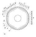
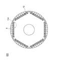
- FIG. 1 is a cross-sectional view of the permanent magnet embedded electric motor according to Embodiment 1 with the rotation center line as a perpendicular line.
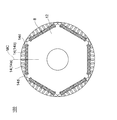
- FIG. 2 is an enlarged view of the single rotor in FIG.
- FIG. 3 is a cross-sectional view showing a state where no permanent magnet is set in the magnet accommodation hole in FIG. 2.
- an embedded permanent magnet electric motor 50 includes an annular stator 1 and a rotor 100.
- the stator 1 includes a ring-shaped stator core 2 and a circumferential portion (a circle centered on the rotation center line in a plane perpendicular to the rotation center line of the rotor) in an inner peripheral side portion of the stator core 2.
- a plurality of slots 3 formed at equiangular pitches in the circumferential direction and the rotation trajectory direction of the rotor 100 and coils 4 accommodated in the slots 3 are provided.
- 1 is a distributed winding stator as an example, but may be a concentrated winding stator.
- the rotor 100 is rotatably disposed in the annular inner space of the stator 1.
- a cylindrical gap 5 is formed between the outer peripheral surface 15 of the rotor 100 (rotor core 12) and the inner peripheral surface 1 a of the stator 1.
- the rotor 100 includes a rotating shaft 11, a rotor core 12, and a plurality of permanent magnets 14 as main components. Rotational energy from the drive source is transmitted to the rotary shaft 11, and the rotor core 12 provided around the rotary shaft 11 is rotated by the rotational energy.
- the rotor core 12 and the rotating shaft 11 are connected by, for example, shrink fitting and press fitting.
- FIG. 2 shows the rotor core 12 before the permanent magnet 14 is accommodated.
- the rotor core 12 is manufactured by laminating a plurality of silicon steel plates (component plates) punched into a predetermined shape with a mold in the direction in which the rotation shaft 11 extends (the front and back direction in FIG. 2).
- the outer peripheral surface 15 of the rotor core 12 is formed in a cylindrical shape.
- the rotor core 12 has six magnet housing holes 13 arranged along the circumferential direction. That is, the first embodiment exemplifies a 6-pole embedded permanent magnet electric motor. However, it is not intended to limit the number of poles of the permanent magnet embedded electric motor according to the present invention.
- the six magnet housing holes 13 have the same shape. Each of the six magnet accommodation holes 13 extends over an equal angular range, and the positions of the respective portions of the magnet accommodation holes 13 in the radial direction are the same in the six magnet accommodation holes 13.
- Each of the magnet housing holes 13 has an outer defining line 13a, an inner defining line 13b, and a pair of end lines 13c.
- the outer demarcation line 13a and the inner demarcation line 13b indicate the inner side and the outer side as viewed in the radial direction (the direction of the radius around the rotation center line in the plane having the rotation center line of the rotor as a perpendicular line).
- the pair of end lines 13c connect the end portion 13d of the outer demarcating line 13a and the end portion 13e of the inner demarcating line 13b in the vicinity of the outer peripheral surface 15 of the rotor core 12. Most of the outer demarcating line 13a and the inner demarcating line 13b (excluding the ends) extend in a direction perpendicular to the radial direction. Each of the end lines 13c is closer to the outer peripheral surface 15 of the rotor core 12 than the outer defining line 13a, and a so-called flux barrier is formed on the radially inner side of the end line 13c.
- the rotor core 12 includes an outer thin core portion 6 between the outer peripheral surface 15 of the rotor core 12 and each end line 13c of each magnet housing hole 13.
- the rotor core 12 By configuring the rotor core 12 in this way, the magnetic resistance in the vicinity of both end portions (end line 13c) of the magnet housing hole 13 can be increased. Thereby, the short circuit magnetic flux of a magnet can be reduced and high torque can be realized.
- a pair of protrusions 7 are formed at both ends of the inner demarcation line 13b of each magnet accommodation hole 13.
- a pair of projection part 7 protrudes toward a radial direction outer side.
- the height of the protrusion 7 is secured such that when the permanent magnet 14 is inserted, the end face 14d on the interpolar side in the longitudinal direction of the permanent magnet 14 and the side surface of the protrusion 7 can be in surface contact.
- the surface contact portion only needs to have a dimension that can prevent displacement of the permanent magnet 14 at the lower limit of the dimensional tolerance of the permanent magnet 14. In this example, it is about 0.5 mm.
- each of the magnet housing holes 13 has a pair of recesses 13f recessed inward in the radial direction on the magnetic pole center side in the circumferential direction from the pair of protrusions 7.
- a plurality of (seven) slits 9 (9 a to 9 g) are formed in an iron core portion between the outer demarcating line 13 a of each magnet accommodation hole 13 and the outer peripheral surface 15.
- the slit 9 (9a to 9g) has no opening connected to the magnet housing hole 13 and the outer peripheral surface 15, and has a closed shape inside the rotor core 12.
- the plurality of slits 9 extend substantially in the radial direction, and the slit 9d at the central part of the magnetic pole is the longest in terms of the length extending in the substantially radial direction, and approaches the inter-polar part. The length decreases, and the slits 9a and 9g at the inter-electrode portions are the shortest.
- thin outer core portions 17 (17 a to 17 g) are formed between each of the plurality of slits 9 and the outer peripheral surface 15.
- a thin inner core is formed between the plurality of slits 9 (9a to 9g) and the outer demarcating line 13a of the magnet housing hole 13 arranged to face the slits 9 (9a to 9g). Portions 18 (18a to 18g) are formed.
- each of the plurality of outer iron core portions 17 and the plurality of inner iron core portions 18 is configured to be approximately the thickness of the electromagnetic steel sheet. For example, it is about 0.2 mm to 0.5 mm.
- each of the magnet housing holes 13 has two flat magnets 14 (14a, 14b) in a circumferential direction per pole (a shape having a rectangular cross section in the cross section of FIG. 3, etc.). Are housed side by side.
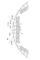
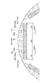
- FIGS. 4 is an enlarged view of the peripheral portion of the magnet accommodation hole for one pole in FIG. 2
- FIG. 5 is an enlarged view of the V portion of FIG.
- the permanent magnets 14 are arranged in the circumferential direction of the rotor core 12 by the number twice the number of poles. And the two permanent magnets 14 arrange
- the permanent magnet 14 is an Nd / Fe / B rare earth magnet and is magnetized so that the directions of the N pole and the S pole are alternated every two pieces as seen in the circumferential direction as described above.
- the two permanent magnets 14 inserted into the corresponding magnet accommodation holes 13 have the same size.
- a space portion 8 is secured between the two permanent magnets 14 inserted in the corresponding magnet housing holes 13.
- the space portion 8 faces any one slit 9 in a direction parallel to the magnetic pole center line MC (see FIG. 3).
- two permanent magnets 14 having the same shape are disposed in each of the magnet housing holes 13, and the space portion 8 is located on the magnetic pole center line.
- the plurality of slits 9 have one slit 9d located on the magnetic pole center line, and the other slits are formed symmetrically with respect to the magnetic pole center line.
- the space portion 8 faces the slit 9d in a direction parallel to the magnetic pole center line, and more specifically, both the space portion 8 and the slit 9d are on the magnetic pole center line.
- the first embodiment is not limited to this, and it is sufficient that the space portion 8 faces any one slit 9 in a direction parallel to the magnetic pole center line, and faces each other.
- the space portion and the slit are not limited to be located on the magnetic pole center line itself.
- the circumferential width (width in the direction perpendicular to the magnetic pole center line) of the space portion 8 between the two permanent magnets 14 (14 a, 14 b) is W 1 and faces the space portion 8.
- W1 the circumferential width of the central slit 9d provided at the position
- the rotor core is provided with a plurality of slits, it is possible to suppress the flow of the stator reaction magnetic flux MA traveling in the circumferential direction from the stator that may cause noise and vibration. Thereby, noise and vibration during operation of the permanent magnet embedded motor can be suppressed. Further, by inserting two permanent magnets into each of the magnet housing holes and providing a space between the permanent magnets, as shown in FIG.
- the permanent magnet embedded motor is configured to satisfy the relationship of W1 ⁇ W2, where W1 is the circumferential width of the space and W2 is the circumferential width of the slit at the position facing the space. Therefore, the magnetic flux density in the portion between the plurality of slits and the plurality of permanent magnets can be increased while suppressing the decrease in the magnetic flux of the permanent magnet. In addition, since the two permanent magnets are inserted into the corresponding magnet receiving holes and the permanent magnets have the same size, the above-described advantages can be obtained while suppressing the cost of the permanent magnets having a large number of installations. It becomes possible.
- FIGS. 6 and 7 are views of the same mode as FIGS. 3 and 4 in the second embodiment of the present invention.
- the second embodiment is the same as the first embodiment described above except for the parts described below.
- the rotor of the first embodiment two magnets are arranged per pole, whereas in the rotor 200 of the second embodiment, three permanent magnets 114 (114a, 114b per pole) are arranged. 114c).
- Space portions 108 (108a, 108b) are provided between the adjacent permanent magnets 114 at positions facing the slits, as in the first embodiment.
- the circumferential width of the space portion 108 between the adjacent permanent magnets 114 is larger than the circumferential width of the corresponding slit 109 facing the space portion 108. small. This will be described more specifically.
- the circumferential width of the space 108a between the two permanent magnets 114a and 114b is W1a
- the circumferential width of the space 108b between the other two permanent magnets 114b and 114c is W1b.
- W1a ⁇ W2a and W1b
- W2a is the circumferential width of the slit 9b provided at the position facing the space 108a
- W2b is the circumferential width of the slit 9f disposed at the position facing the other space portion 108b.
- W1a W1b
- W2a W2b.
- the permanent magnets 114a and 114c are arranged in the middle in the magnet accommodation hole 13 with the circumferential widths M1 and M3 arranged at both ends in the direction orthogonal to the magnetic pole center line.
- M1 M2
- M1 M3
- the flow of the stator reaction magnetic flux that travels in the substantially circumferential direction from the stator similarly to the first embodiment, the flow of the stator reaction magnetic flux that travels in the substantially circumferential direction from the stator. It is possible to suppress the vibration force in the radial direction.
- the loss of the permanent magnets at both ends having a large eddy current loss can be effectively reduced, the heat generation of the magnet can be suppressed, and the demagnetization resistance can be improved.
- the magnetic flux produced by the stator winding passes through the slits and is substantially perpendicular to the longitudinal direction of the magnet (direction perpendicular to the magnetic pole center line). Flowing into. At this time, if the magnitude of the magnetic flux generated by the stator winding changes, an eddy current flows inside the magnet, which may cause a loss and increase the temperature of the magnet. The eddy current flows particularly concentrated on the end portion of the magnet.
- Embodiment 2 the electrical resistance of the magnets at both ends can be increased by making the circumferential width of the magnets at both ends smaller than the circumferential width of the other magnets. Can be reduced.
- this Embodiment 2 since three magnets are arrange
- the circumferential width of the permanent magnets at both ends is the remaining one other than both ends (the remaining one other than both ends when three magnets are arranged in the magnet accommodation holes) or two or more ( It is smaller than the circumferential width of the permanent magnets of the remaining permanent magnets except for both ends when four or more magnets are arranged in the magnet housing hole.
- Embodiment 3 a permanent magnet embedded electric motor according to Embodiment 3 of the present invention will be described.
- the third embodiment is configured as shown in FIGS. 6 and 7 as an example, and is the same as the above-described second embodiment except for the portions described below.
- the coercive force of the permanent magnets arranged on both end sides is set to the remaining one other than both end sides (in the magnet accommodation holes). Permanent of remaining one other than both ends when three magnets are arranged) or two or more (all remaining other than both ends when four or more magnets are arranged in the magnet accommodation hole) It is larger than the coercive force of the magnet.
- the permanent magnet embedded electric motor according to the third embodiment configured as described above also suppresses the flow of the stator reaction magnetic flux that travels in the substantially circumferential direction from the stator, as in the first embodiment. It is possible to reduce the radial excitation force. In addition, eddy current can be reduced as in the second embodiment.
- the permanent magnet embedded type electric motor is used in a high-temperature atmosphere in the compressor by relatively increasing the coercive force of the permanent magnets at both ends in the magnet housing hole. Even in this case, it is expected to provide a high-output electric motor suitable for high-speed and high-torque driving without demagnetizing the magnet.
- Embodiment 4 FIG. Next, as Embodiment 4 of the present invention, a rotary compressor on which the permanent magnet embedded type electric motor of any of Embodiments 1 to 3 described above is mounted will be described.
- the present invention includes a compressor equipped with the permanent magnet embedded type electric motor according to any of the first to third embodiments described above, but the type of the compressor is not limited to the rotary compressor. .
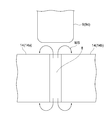
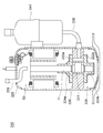
- FIG. 8 is a longitudinal sectional view of a rotary compressor equipped with a permanent magnet embedded type electric motor.
- the rotary compressor 250 includes a permanent magnet embedded electric motor 50 (electric element) and a compression element 230 in an airtight container 225.
- refrigerating machine oil that lubricates each sliding portion of the compression element 230 is stored at the bottom of the sealed container 225.
- the compression element 230 includes, as main elements, a cylinder 220 provided in a vertically stacked state, a rotary shaft 11 that is rotated by an electric motor, a piston 221 that is fitted into the rotary shaft 11, and a suction side and a compression side inside the cylinder 220. And a pair of upper and lower frames 222a and 222b, and an upper frame 222a and a lower frame 222b, which are rotatably inserted into the vane (not shown), and the rotation shaft 11 is rotatably inserted and closes the axial end surface of the cylinder 220. Each includes a muffler 224a and 224b mounted.
- the stator 1 of the embedded permanent magnet electric motor 50 is directly attached and held in the sealed container 225 by a method such as shrink fitting or welding. Electric power is supplied to the coil 4 of the stator 1 from a glass terminal fixed to the hermetic container 225.
- the rotor 100 is arranged through a gap provided on the inner diameter side of the stator 1, and a bearing of a compression element 230 provided at the lower part of the rotary compressor 250 via the rotary shaft 11 at the center of the rotor 100. It is held in a freely rotatable state by the parts (upper frame 222a and lower frame 222b).
- the refrigerant gas supplied from the accumulator 241 is sucked into the cylinder 220 through the suction pipe 228 fixed to the sealed container 25.
- the permanent magnet embedded type electric motor 50 is rotated by energization of the inverter, so that the piston 221 fitted to the rotary shaft 11 is rotated in the cylinder 220.
- the refrigerant is compressed in the cylinder 220.
- the compressed high-temperature refrigerant passes through the mufflers 224a and 224b, and then goes up through the air holes of the embedded permanent magnet electric motor 50 and the like in the sealed container 25.
- the compressed refrigerant is supplied to the high-pressure side of the refrigeration cycle through the discharge pipe 229 provided in the sealed container 225.
- any refrigerant such as a low GWP (global warming potential) refrigerant can be applied. From the viewpoint of preventing global warming, a low GWP refrigerant is desired.
- the low GWP refrigerant there are the following refrigerants.
- HFO is an abbreviation for Hydro-Fluoro-Olefin
- Olefin is an unsaturated hydrocarbon having one double bond.
- the GFO of HFO-1234yf is 4.
- Hydrocarbon having a carbon double bond in the composition for example, R1270 (propylene).
- GWP is 3, which is smaller than HFO-1234yf, but flammability is larger than HFO-1234yf.
- a mixture containing at least one of a halogenated hydrocarbon having a carbon double bond in the composition or a hydrocarbon having a carbon double bond in the composition for example, a mixture of HFO-1234yf and R32 is there. Since HFO-1234yf is a low-pressure refrigerant, its pressure loss is large, and the performance of the refrigeration cycle (especially in an evaporator) tends to deteriorate. Therefore, a mixture with R32 or R41, which is a high-pressure refrigerant, is more effective than HFO-1234yf in practical use.
- R32 refrigerant is notable for toxicity and is not highly flammable, and thus has received particular attention. Further, when the R32 refrigerant is used for the rotary compressor 250, the internal temperature of the rotary compressor 250 is higher by about 20 ° C. or more than R410A, R407C, R22 and the like conventionally used.
- the temperature inside the rotary compressor 250 varies depending on the compression load state (rotation speed, compression load torque, refrigerant), and in the steady state where the temperature is stable, the dependence on the rotation speed is particularly high.
- the temperature rise inside the rotary compressor with respect to the rotational speed when using R410 refrigerant is 70 to 80 ° C. for medium speed operation and 90 to 110 ° C. for high speed operation, compared to 50 to 60 ° C. for low speed operation.
- the temperature inside the rotary compressor 250 increases.
- the temperature in the rotary compressor 250 further increases by about 20 ° C. relative to the R410A refrigerant.
- the rotary compressor constructed as described above uses a permanent magnet embedded type electric motor having a large demagnetization resistance. Therefore, even if the J coercive force is lowered due to a rise in the temperature of the compressor, the magnet is demagnetized. There is an effect that it is possible to provide a highly reliable compressor that does not generate any problems.
- the embedded permanent magnet electric motor is operated in a high-temperature atmosphere of a rotary compressor, the residual magnetic flux of the magnet can be reduced while reducing the amount of Dy added to the rare earth magnet and reducing the cost. Since the density can be increased and the torque of the electric motor can be increased, a highly efficient compressor can be provided. Furthermore, since an electric motor having a small radial excitation force is used, vibration and noise of the compressor can be suppressed.
- Embodiment 5 FIG.
- the present invention can also be implemented as a refrigeration air conditioner that includes the compressor of the fourth embodiment described above as a component of the refrigeration circuit.
- the structure of components other than the compressor in the refrigeration circuit of the refrigeration air conditioner is not particularly limited.
- stator 8 108 space, 9 slit, 12 rotor core, 13 magnet housing hole, 13a outer demarcation line, 14, 114 permanent magnet, 15 outer peripheral surface, 100, 200 rotor, 225 sealed container, 230 compression Element, 250 rotary compressor.
Landscapes
- Engineering & Computer Science (AREA)
- Physics & Mathematics (AREA)
- Mechanical Engineering (AREA)
- Thermal Sciences (AREA)
- General Engineering & Computer Science (AREA)
- Power Engineering (AREA)
- Permanent Field Magnets Of Synchronous Machinery (AREA)
- Iron Core Of Rotating Electric Machines (AREA)
- Compressor (AREA)
- Applications Or Details Of Rotary Compressors (AREA)
Abstract
Description
前記空間部の周方向幅をW1とし、該空間部と対向する位置にある前記スリットの周方向幅をW2とすると、W1≦W2であるように構成してもよい。
前記磁石収容穴のそれぞれには、2つの前記永久磁石が挿入されており、これら永久磁石は、同一サイズであるように構成してもよい。
あるいは、前記磁石収容穴のそれぞれには、3つの前記永久磁石又は4つ以上の前記永久磁石が挿入されており、両端側の前記永久磁石の周方向幅は、両端側以外の1つ前記永久磁石の周方向幅又は両端側以外の2つ以上の前記永久磁石の周方向幅よりも小さいように構成してもよい。
その場合、両端側の前記永久磁石の保磁力は、両端側以外の1つ前記永久磁石の保磁力又は両端側以外の2つ以上の前記永久磁石の保磁力よりも大きいように構成してもよい。
さらに、同目的を達成するための本発明に係る圧縮機は、密閉容器内に、電動機と、圧縮要素とを備えた圧縮機であって、前記電動機は、上述した本発明に係る永久磁石埋込型電動機である。
さらに、同目的を達成するための本発明に係る冷凍空調装置は、上述した本発明に係る圧縮機を冷凍回路の構成要素として含む。
図1は、本実施の形態1に係る永久磁石埋込型電動機の、回転中心線を垂線とする断面図である。図2は、図1における回転子単体を拡大して示す図である。図3は、図2において、磁石収容穴に永久磁石をセットしていない状態を示す断面図である。
次に、本発明の実施の形態2に係る永久磁石埋込型電動機について説明する。図6及び図7はそれぞれ、本発明の実施の形態2に関する、図3及び図4と同態様の図である。なお、本実施の形態2は、以下に説明する部分を除いては、上述した実施の形態1と同様であるものとする。
次に、本発明の実施の形態3に係る永久磁石埋込型電動機について説明する。本実施の形態3は、一例として、図6及び図7のように構成されており、さらに、以下に説明する部分を除いては、上述した実施の形態2と同様であるものとする。
次に、本発明の実施の形態4として、上述した実施の形態1~3の何れかの永久磁石埋込型電動機を搭載したロータリ圧縮機について説明する。なお、本発明は、上述した実施の形態1~3の何れかの永久磁石埋込型電動機を搭載した圧縮機を含むものであるが、圧縮機の種別は、ロータリ圧縮機に限定されるものではない。
(2)組成中に炭素の二重結合を有する炭化水素:例えば、R1270(プロピレン)である。尚、GWPは3で、HFO-1234yfより小さいが、可燃性はHFO-1234yfより大きい。
(3)組成中に炭素の二重結合を有するハロゲン化炭化水素または組成中に炭素の二重結合を有する炭化水素の少なくともいずれかを含む混合物:例えば、HFO-1234yfとR32との混合物等である。HFO-1234yfは、低圧冷媒のため圧損が大きくなり、冷凍サイクル(特に、蒸発器において)の性能が低下しやすい。そのため、HFO-1234yfより高圧冷媒であるR32又はR41等との混合物が実用上は有力になる。
また、本発明は、上述した実施の形態4の圧縮機を冷凍回路の構成要素として含む、冷凍空調装置として実施することも可能である。なお、冷凍空調装置の冷凍回路における、圧縮機以外の構成要素の構成は、特に、限定されるものではない。上記圧縮機を冷凍空調装置に用いることで、配管を経由した振動の伝達を抑制し、振動・騒音を抑制することができる。
Claims (9)
- 固定子と、
前記固定子に対向して回転可能に設けられた回転子とを備え、
前記回転子は、複数の磁石収容穴を有する回転子鉄心を含み、
前記磁石収容穴のそれぞれに、複数の永久磁石が収容されており、
前記回転子鉄心における前記回転子の外周面とそれぞれの前記磁石収容穴の外側画定ラインとの間には、複数のスリットが形成されている、永久磁石埋込型電動機であって、
前記磁石収容穴に挿入された状態の前記複数の永久磁石の間には、少なくとも一つの空間部が形成されており、該空間部は、前記複数のスリットの何れか一つと、磁極中心線に平行な方向に対向する、
永久磁石埋込型電動機。 - 前記空間部の周方向幅をW1とし、該空間部と対向する位置にある前記スリットの周方向幅をW2とすると、W1≦W2である、
請求項1の永久磁石埋込型電動機。 - 前記磁石収容穴のそれぞれには、2つの前記永久磁石が挿入されており、
これら永久磁石は、同一サイズである、
請求項1又は2の永久磁石埋込型電動機。 - 前記磁石収容穴のそれぞれには、3つの前記永久磁石が挿入されており、
両端側の前記永久磁石の周方向幅は、両端側以外の1つ前記永久磁石の周方向幅よりも小さい、
請求項1又は2の永久磁石埋込型電動機。 - 両端側の前記永久磁石の保磁力は、両端側以外の1つ前記永久磁石の保磁力よりも大きい、
請求項4の永久磁石埋込型電動機。 - 前記磁石収容穴のそれぞれには、4つ以上の前記永久磁石が挿入されており、
両端側の前記永久磁石の周方向幅は、両端側以外の2つ以上の前記永久磁石の周方向幅よりも小さい、
請求項1又は2の永久磁石埋込型電動機。 - 両端側の前記永久磁石の保磁力は、両端側以外の2つ以上の前記永久磁石の保磁力よりも大きい、
請求項6の永久磁石埋込型電動機。 - 密閉容器内に、電動機と、圧縮要素とを備えた圧縮機であって、
前記電動機は、請求項1~7の何れか一項の永久磁石埋込型電動機である、
圧縮機。 - 請求項8の圧縮機を冷凍回路の構成要素として含む、冷凍空調装置。
Priority Applications (6)
| Application Number | Priority Date | Filing Date | Title |
|---|---|---|---|
| EP13898601.3A EP3079231B1 (en) | 2013-12-05 | 2013-12-05 | Permanent magnet-embedded electric motor, compressor, and refrigerating and air-conditioning device |
| CN201380081174.9A CN105794087B (zh) | 2013-12-05 | 2013-12-05 | 永久磁铁埋入式电动机、压缩机以及制冷空调装置 |
| PCT/JP2013/082730 WO2015083274A1 (ja) | 2013-12-05 | 2013-12-05 | 永久磁石埋込型電動機、圧縮機及び冷凍空調装置 |
| JP2015551348A JP6109338B2 (ja) | 2013-12-05 | 2013-12-05 | 永久磁石埋込型電動機、圧縮機及び冷凍空調装置 |
| US15/033,923 US10103588B2 (en) | 2013-12-05 | 2013-12-05 | Permanent magnet-embedded electric motor, compressor, and refrigerating and air-conditioning device |
| CN201420735487.3U CN204376560U (zh) | 2013-12-05 | 2014-11-28 | 永磁铁埋入型电动机、压缩机以及制冷空调装置 |
Applications Claiming Priority (1)
| Application Number | Priority Date | Filing Date | Title |
|---|---|---|---|
| PCT/JP2013/082730 WO2015083274A1 (ja) | 2013-12-05 | 2013-12-05 | 永久磁石埋込型電動機、圧縮機及び冷凍空調装置 |
Publications (1)
| Publication Number | Publication Date |
|---|---|
| WO2015083274A1 true WO2015083274A1 (ja) | 2015-06-11 |
Family
ID=53273066
Family Applications (1)
| Application Number | Title | Priority Date | Filing Date |
|---|---|---|---|
| PCT/JP2013/082730 Ceased WO2015083274A1 (ja) | 2013-12-05 | 2013-12-05 | 永久磁石埋込型電動機、圧縮機及び冷凍空調装置 |
Country Status (5)
| Country | Link |
|---|---|
| US (1) | US10103588B2 (ja) |
| EP (1) | EP3079231B1 (ja) |
| JP (1) | JP6109338B2 (ja) |
| CN (2) | CN105794087B (ja) |
| WO (1) | WO2015083274A1 (ja) |
Cited By (2)
| Publication number | Priority date | Publication date | Assignee | Title |
|---|---|---|---|---|
| WO2020213081A1 (ja) * | 2019-04-17 | 2020-10-22 | 三菱電機株式会社 | ロータ、モータ、圧縮機、及び空気調和機 |
| DE102018126147B4 (de) | 2017-10-30 | 2024-12-19 | Okuma Corporation | Rotor eines Synchronmotors |
Families Citing this family (21)
| Publication number | Priority date | Publication date | Assignee | Title |
|---|---|---|---|---|
| WO2017138142A1 (ja) * | 2016-02-12 | 2017-08-17 | 三菱電機株式会社 | 電動機、圧縮機及び冷凍空調装置 |
| TWM576750U (zh) | 2017-07-25 | 2019-04-11 | 美商米沃奇電子工具公司 | 電氣組合物、電動化裝置系統、電池組、電馬達、馬達總成及電馬達總成 |
| US11493244B2 (en) | 2017-12-18 | 2022-11-08 | Daikin Industries, Ltd. | Air-conditioning unit |
| US12379140B2 (en) | 2017-12-18 | 2025-08-05 | Daikin Industries., Ltd. | Air conditioner |
| US11441802B2 (en) | 2017-12-18 | 2022-09-13 | Daikin Industries, Ltd. | Air conditioning apparatus |
| US12270575B2 (en) | 2017-12-18 | 2025-04-08 | Daikin Industries, Ltd. | Warm-water generating apparatus |
| BR112020010634A2 (pt) | 2017-12-18 | 2020-11-10 | Daikin Industries, Ltd. | composição compreendendo refrigerante, uso da mesma, máquina de refrigeração tendo a mesma, e método para operação da dita máquina de refrigeração |
| US11820933B2 (en) | 2017-12-18 | 2023-11-21 | Daikin Industries, Ltd. | Refrigeration cycle apparatus |
| CN111511874A (zh) | 2017-12-18 | 2020-08-07 | 大金工业株式会社 | 制冷循环装置 |
| US11365335B2 (en) | 2017-12-18 | 2022-06-21 | Daikin Industries, Ltd. | Composition comprising refrigerant, use thereof, refrigerating machine having same, and method for operating said refrigerating machine |
| US11441819B2 (en) | 2017-12-18 | 2022-09-13 | Daikin Industries, Ltd. | Refrigeration cycle apparatus |
| US11435118B2 (en) | 2017-12-18 | 2022-09-06 | Daikin Industries, Ltd. | Heat source unit and refrigeration cycle apparatus |
| US11549695B2 (en) | 2017-12-18 | 2023-01-10 | Daikin Industries, Ltd. | Heat exchange unit |
| US11549041B2 (en) | 2017-12-18 | 2023-01-10 | Daikin Industries, Ltd. | Composition containing refrigerant, use of said composition, refrigerator having said composition, and method for operating said refrigerator |
| US11506425B2 (en) | 2017-12-18 | 2022-11-22 | Daikin Industries, Ltd. | Refrigeration cycle apparatus |
| US11906207B2 (en) | 2017-12-18 | 2024-02-20 | Daikin Industries, Ltd. | Refrigeration apparatus |
| JP7019033B2 (ja) | 2018-04-10 | 2022-02-14 | 三菱電機株式会社 | 電動機、圧縮機および空気調和装置 |
| WO2020172180A1 (en) | 2019-02-18 | 2020-08-27 | Milwaukee Electric Tool Corporation | Impact tool |
| JP7389146B2 (ja) * | 2020-02-07 | 2023-11-29 | 三菱電機株式会社 | 回転子、電動機、圧縮機、冷凍サイクル装置、及び空気調和装置 |
| TWI765536B (zh) * | 2021-01-19 | 2022-05-21 | 國立成功大學 | 馬達及其轉子構造 |
| US11791678B2 (en) | 2021-02-25 | 2023-10-17 | National Cheng Kung University | Motor and rotor structure thereof |
Citations (5)
| Publication number | Priority date | Publication date | Assignee | Title |
|---|---|---|---|---|
| JP2007174776A (ja) | 2005-12-21 | 2007-07-05 | Daikin Ind Ltd | モータおよび圧縮機 |
| JP2008022601A (ja) * | 2006-07-11 | 2008-01-31 | Mitsubishi Electric Corp | 回転子及び密閉型圧縮機及び冷凍サイクル装置 |
| JP2011078283A (ja) * | 2009-10-01 | 2011-04-14 | Mitsubishi Electric Corp | 永久磁石埋込型モータの回転子及び送風機及び圧縮機 |
| JP2012050331A (ja) * | 2011-12-05 | 2012-03-08 | Mitsubishi Electric Corp | 電動機 |
| JP2012105410A (ja) * | 2010-11-09 | 2012-05-31 | Mitsubishi Electric Corp | 電動機及び圧縮機 |
Family Cites Families (9)
| Publication number | Priority date | Publication date | Assignee | Title |
|---|---|---|---|---|
| DE2527461C2 (de) * | 1975-06-20 | 1987-01-02 | Robert Bosch Gmbh, 7000 Stuttgart | Verfahren zur Herstellung von anisotropen Segmentmagneten für elektrische Maschinen |
| EP0729216A3 (de) * | 1995-02-21 | 1998-03-11 | Siemens Aktiengesellschaft | Hybriderregte Synchronmaschine |
| JP2000228838A (ja) * | 1998-12-01 | 2000-08-15 | Toyota Motor Corp | 永久磁石モータ |
| DE69928363T2 (de) * | 1998-12-25 | 2006-06-01 | Matsushita Electric Industrial Co., Ltd., Kadoma | Motor mit im Rotor eingebetteten geteilten Dauermagneten |
| JP4485225B2 (ja) | 2004-02-27 | 2010-06-16 | 三菱電機株式会社 | 永久磁石型モータ及び密閉型圧縮機及びファンモータ |
| JP4815204B2 (ja) * | 2005-12-01 | 2011-11-16 | アイチエレック株式会社 | 永久磁石回転機及び圧縮機 |
| US7932658B2 (en) * | 2007-03-15 | 2011-04-26 | A.O. Smith Corporation | Interior permanent magnet motor including rotor with flux barriers |
| JP5268711B2 (ja) | 2009-03-02 | 2013-08-21 | 三菱電機株式会社 | 電動機及び圧縮機及び空気調和機及び電気掃除機 |
| JP5752260B2 (ja) * | 2011-11-07 | 2015-07-22 | 三菱電機株式会社 | 永久磁石埋込型電動機の回転子、及びこの回転子を用いた電動機、及びこの電動機を用いた圧縮機、及びこの圧縮機を用いた空気調和機 |
-
2013
- 2013-12-05 JP JP2015551348A patent/JP6109338B2/ja not_active Expired - Fee Related
- 2013-12-05 EP EP13898601.3A patent/EP3079231B1/en not_active Not-in-force
- 2013-12-05 CN CN201380081174.9A patent/CN105794087B/zh not_active Expired - Fee Related
- 2013-12-05 US US15/033,923 patent/US10103588B2/en active Active
- 2013-12-05 WO PCT/JP2013/082730 patent/WO2015083274A1/ja not_active Ceased
-
2014
- 2014-11-28 CN CN201420735487.3U patent/CN204376560U/zh not_active Expired - Lifetime
Patent Citations (5)
| Publication number | Priority date | Publication date | Assignee | Title |
|---|---|---|---|---|
| JP2007174776A (ja) | 2005-12-21 | 2007-07-05 | Daikin Ind Ltd | モータおよび圧縮機 |
| JP2008022601A (ja) * | 2006-07-11 | 2008-01-31 | Mitsubishi Electric Corp | 回転子及び密閉型圧縮機及び冷凍サイクル装置 |
| JP2011078283A (ja) * | 2009-10-01 | 2011-04-14 | Mitsubishi Electric Corp | 永久磁石埋込型モータの回転子及び送風機及び圧縮機 |
| JP2012105410A (ja) * | 2010-11-09 | 2012-05-31 | Mitsubishi Electric Corp | 電動機及び圧縮機 |
| JP2012050331A (ja) * | 2011-12-05 | 2012-03-08 | Mitsubishi Electric Corp | 電動機 |
Non-Patent Citations (1)
| Title |
|---|
| See also references of EP3079231A4 * |
Cited By (4)
| Publication number | Priority date | Publication date | Assignee | Title |
|---|---|---|---|---|
| DE102018126147B4 (de) | 2017-10-30 | 2024-12-19 | Okuma Corporation | Rotor eines Synchronmotors |
| WO2020213081A1 (ja) * | 2019-04-17 | 2020-10-22 | 三菱電機株式会社 | ロータ、モータ、圧縮機、及び空気調和機 |
| JPWO2020213081A1 (ja) * | 2019-04-17 | 2021-10-14 | 三菱電機株式会社 | ロータ、モータ、圧縮機、及び空気調和機 |
| JP7204897B2 (ja) | 2019-04-17 | 2023-01-16 | 三菱電機株式会社 | ロータ、モータ、圧縮機、及び空気調和機 |
Also Published As
| Publication number | Publication date |
|---|---|
| CN105794087A (zh) | 2016-07-20 |
| JP6109338B2 (ja) | 2017-04-05 |
| EP3079231A1 (en) | 2016-10-12 |
| JPWO2015083274A1 (ja) | 2017-03-16 |
| CN204376560U (zh) | 2015-06-03 |
| US10103588B2 (en) | 2018-10-16 |
| EP3079231B1 (en) | 2019-02-13 |
| CN105794087B (zh) | 2019-01-08 |
| US20160276886A1 (en) | 2016-09-22 |
| EP3079231A4 (en) | 2017-08-23 |
Similar Documents
| Publication | Publication Date | Title |
|---|---|---|
| JP6109338B2 (ja) | 永久磁石埋込型電動機、圧縮機及び冷凍空調装置 | |
| JP6479267B2 (ja) | 固定子、電動機、圧縮機、及び冷凍空調装置 | |
| JP5944014B2 (ja) | 永久磁石埋込型電動機および圧縮機 | |
| JP5971669B2 (ja) | 永久磁石埋込型電動機及び圧縮機 | |
| JP6494871B2 (ja) | 固定子、電動機、圧縮機、及び冷凍空調装置 | |
| JP5971666B2 (ja) | 永久磁石埋込型電動機及び圧縮機 | |
| CN108604840B (zh) | 电动机、压缩机以及制冷空调装置 | |
| WO2015163229A1 (ja) | 永久磁石埋込型電動機、圧縮機、冷凍空調装置 | |
| JP6339103B2 (ja) | 永久磁石埋込型電動機、圧縮機及び冷凍空調装置 | |
| WO2015045026A1 (ja) | 永久磁石埋込型電動機、圧縮機及び冷凍空調装置 | |
| WO2016056065A1 (ja) | 永久磁石埋込型電動機、圧縮機、および冷凍空調機 | |
| JP7154373B2 (ja) | 電動機、圧縮機、及び空気調和機 | |
| WO2013114541A1 (ja) | 永久磁石埋込型電動機および圧縮機 | |
| JP6223568B2 (ja) | 永久磁石埋込型電動機、圧縮機及び冷凍空調装置 | |
| JP5619305B2 (ja) | 永久磁石埋込型電動機および圧縮機 | |
| WO2015198444A1 (ja) | 永久磁石埋込型電動機、圧縮機、冷凍空調装置 |
Legal Events
| Date | Code | Title | Description |
|---|---|---|---|
| 121 | Ep: the epo has been informed by wipo that ep was designated in this application |
Ref document number: 13898601 Country of ref document: EP Kind code of ref document: A1 |
|
| ENP | Entry into the national phase |
Ref document number: 2015551348 Country of ref document: JP Kind code of ref document: A |
|
| WWE | Wipo information: entry into national phase |
Ref document number: 15033923 Country of ref document: US |
|
| REEP | Request for entry into the european phase |
Ref document number: 2013898601 Country of ref document: EP |
|
| WWE | Wipo information: entry into national phase |
Ref document number: 2013898601 Country of ref document: EP |
|
| NENP | Non-entry into the national phase |
Ref country code: DE |