WO2015083427A1 - 電力変換装置 - Google Patents
電力変換装置 Download PDFInfo
- Publication number
- WO2015083427A1 WO2015083427A1 PCT/JP2014/076472 JP2014076472W WO2015083427A1 WO 2015083427 A1 WO2015083427 A1 WO 2015083427A1 JP 2014076472 W JP2014076472 W JP 2014076472W WO 2015083427 A1 WO2015083427 A1 WO 2015083427A1
- Authority
- WO
- WIPO (PCT)
- Prior art keywords
- power
- unit
- power conversion
- voltage
- functional module
- Prior art date
- Legal status (The legal status is an assumption and is not a legal conclusion. Google has not performed a legal analysis and makes no representation as to the accuracy of the status listed.)
- Ceased
Links
Images






Classifications
-
- H—ELECTRICITY
- H02—GENERATION; CONVERSION OR DISTRIBUTION OF ELECTRIC POWER
- H02M—APPARATUS FOR CONVERSION BETWEEN AC AND AC, BETWEEN AC AND DC, OR BETWEEN DC AND DC, AND FOR USE WITH MAINS OR SIMILAR POWER SUPPLY SYSTEMS; CONVERSION OF DC OR AC INPUT POWER INTO SURGE OUTPUT POWER; CONTROL OR REGULATION THEREOF
- H02M7/00—Conversion of AC power input into DC power output; Conversion of DC power input into AC power output
- H02M7/003—Constructional details, e.g. physical layout, assembly, wiring or busbar connections
-
- B—PERFORMING OPERATIONS; TRANSPORTING
- B60—VEHICLES IN GENERAL
- B60L—PROPULSION OF ELECTRICALLY-PROPELLED VEHICLES; SUPPLYING ELECTRIC POWER FOR AUXILIARY EQUIPMENT OF ELECTRICALLY-PROPELLED VEHICLES; ELECTRODYNAMIC BRAKE SYSTEMS FOR VEHICLES IN GENERAL; MAGNETIC SUSPENSION OR LEVITATION FOR VEHICLES; MONITORING OPERATING VARIABLES OF ELECTRICALLY-PROPELLED VEHICLES; ELECTRIC SAFETY DEVICES FOR ELECTRICALLY-PROPELLED VEHICLES
- B60L9/00—Electric propulsion with power supply external to the vehicle
- B60L9/16—Electric propulsion with power supply external to the vehicle using AC induction motors
- B60L9/30—Electric propulsion with power supply external to the vehicle using AC induction motors fed from different kinds of power-supply lines
-
- B—PERFORMING OPERATIONS; TRANSPORTING
- B61—RAILWAYS
- B61D—BODY DETAILS OR KINDS OF RAILWAY VEHICLES
- B61D27/00—Heating, cooling, ventilating, or air-conditioning
-
- H—ELECTRICITY
- H02—GENERATION; CONVERSION OR DISTRIBUTION OF ELECTRIC POWER
- H02M—APPARATUS FOR CONVERSION BETWEEN AC AND AC, BETWEEN AC AND DC, OR BETWEEN DC AND DC, AND FOR USE WITH MAINS OR SIMILAR POWER SUPPLY SYSTEMS; CONVERSION OF DC OR AC INPUT POWER INTO SURGE OUTPUT POWER; CONTROL OR REGULATION THEREOF
- H02M3/00—Conversion of DC power input into DC power output
- H02M3/02—Conversion of DC power input into DC power output without intermediate conversion into AC
- H02M3/04—Conversion of DC power input into DC power output without intermediate conversion into AC by static converters
-
- H—ELECTRICITY
- H02—GENERATION; CONVERSION OR DISTRIBUTION OF ELECTRIC POWER
- H02M—APPARATUS FOR CONVERSION BETWEEN AC AND AC, BETWEEN AC AND DC, OR BETWEEN DC AND DC, AND FOR USE WITH MAINS OR SIMILAR POWER SUPPLY SYSTEMS; CONVERSION OF DC OR AC INPUT POWER INTO SURGE OUTPUT POWER; CONTROL OR REGULATION THEREOF
- H02M7/00—Conversion of AC power input into DC power output; Conversion of DC power input into AC power output
- H02M7/42—Conversion of DC power input into AC power output without possibility of reversal
- H02M7/44—Conversion of DC power input into AC power output without possibility of reversal by static converters
-
- H—ELECTRICITY
- H05—ELECTRIC TECHNIQUES NOT OTHERWISE PROVIDED FOR
- H05K—PRINTED CIRCUITS; CASINGS OR CONSTRUCTIONAL DETAILS OF ELECTRIC APPARATUS; MANUFACTURE OF ASSEMBLAGES OF ELECTRICAL COMPONENTS
- H05K7/00—Constructional details common to different types of electric apparatus
- H05K7/20—Modifications to facilitate cooling, ventilating, or heating
- H05K7/2089—Modifications to facilitate cooling, ventilating, or heating for power electronics, e.g. for inverters for controlling motor
- H05K7/20909—Forced ventilation, e.g. on heat dissipaters coupled to components
-
- B—PERFORMING OPERATIONS; TRANSPORTING
- B60—VEHICLES IN GENERAL
- B60L—PROPULSION OF ELECTRICALLY-PROPELLED VEHICLES; SUPPLYING ELECTRIC POWER FOR AUXILIARY EQUIPMENT OF ELECTRICALLY-PROPELLED VEHICLES; ELECTRODYNAMIC BRAKE SYSTEMS FOR VEHICLES IN GENERAL; MAGNETIC SUSPENSION OR LEVITATION FOR VEHICLES; MONITORING OPERATING VARIABLES OF ELECTRICALLY-PROPELLED VEHICLES; ELECTRIC SAFETY DEVICES FOR ELECTRICALLY-PROPELLED VEHICLES
- B60L2200/00—Type of vehicles
- B60L2200/26—Rail vehicles
Definitions
- the present invention relates to a power conversion device that converts power using semiconductor components.
- a power conversion device provided in a railway vehicle includes a heat generating unit having various semiconductor units and a heat radiating unit that cools the heat generating unit, and the heat generating unit and the heat radiating unit can be separated from each other.
- a power conversion device with improved workability and maintainability has been proposed (see, for example, Patent Document 1).
- a power conversion device used for a railway vehicle needs to cope with a plurality of different power sources depending on a region such as a difference between direct current and alternating current or a difference between single phase alternating current and three phase alternating current.
- the power conversion device described in Patent Document 1 has a structure in which semiconductor components are mounted on one substrate so as to satisfy necessary power conversion characteristics. Therefore, it is necessary to rearrange the entire power conversion device.
- the present invention has been made in order to solve the above-described problems, and an object of the present invention is to provide a power conversion device that can share semiconductor components and suppress a decrease in reliability. is there.
- a power conversion device is a power conversion device that is supplied to an air conditioner provided in a railway vehicle, and includes a functional module that is composed of semiconductor components and on which a power conversion unit for converting power is mounted.
- a functional module in which a rectifier unit that rectifies AC voltage supplied from the outside and an inverter unit that converts DC voltage to AC power, and a converter that converts AC voltage to DC voltage Any one or more of a functional module in which a unit and an inverter unit that converts DC voltage converted by the converter unit into AC power and a function module that includes an inverter unit that converts DC voltage into AC power are provided
- the functional module cools the semiconductor component Those having that cooler.
- the power converter is configured by combining functional modules so as to exhibit the necessary capability, thereby promoting the common use of the semiconductor components and increasing the reliability of the number of semiconductor components. Can be suppressed.
- FIG. 1 is a diagram illustrating an example of an arrangement configuration of functional modules in the power conversion device according to Embodiment 1 of the present invention
- FIG. 2 illustrates an example of a functional configuration of the power conversion device according to Embodiment 1 of the present invention.
- the power conversion device 2 includes a cooling fan unit 21, a capacitor unit 4, and a power converter 5.
- the cooling fan unit 21 includes a plurality of cooling fans 23.
- the power converter 5 is accommodated in the accommodating portion 50, and the sealed chamber 8 and the open chamber 9 are accommodated in the accommodating portion 50.
- the sealed chamber 8 is a space sealed from the outside.
- the open chamber 9 is a space having an opening that communicates with outside air.
- a cooler 6 is disposed in the open chamber 9.
- a power converter 5 is disposed in the sealed chamber 8 to prevent dust and water resistance, especially iron powder and the like from being mixed into the functional module for deterioration due to railway vehicles.
- the power converter 5 includes a functional module 7_1, a functional module 7_2, and a functional module 7_3.
- the functional module one or a plurality of power conversion units for performing power conversion are formed, and the one or a plurality of power conversion units are configured using semiconductor components.
- Each of the function modules 7_1 to 7_3 is detachably provided to the capacitor unit 4.
- the function module 7_3 is replaced with a fourth function module 7_4 having another power conversion characteristic as necessary. It has a configuration that can.
- the power converter 5 is illustrated as having three function modules 7_1 to 7_3, the number and shape of the function modules are not particularly limited, and may be one or more.
- the functional module 7_1 includes a rectifier unit 15_1 that rectifies an AC voltage supplied from the outside, and an inverter unit 11_1 that converts the DC voltage converted by the rectifier unit 15_1 into AC power.
- the rectifier unit 15_1 converts single-phase or three-phase AC power into a DC voltage.
- the inverter unit 11_1 converts the DC voltage converted by the rectifier unit 15_1 into preset three-phase AC power.
- the functional module 7_2 includes a converter unit 13_2 that converts a fluctuating input voltage supplied from the outside into a stable DC voltage, and an inverter unit 11_2 that converts the DC voltage converted by the converter unit into AC power.
- Converter unit 13_2 converts the fluctuating input voltage into a stable DC voltage.
- Inverter unit 11_2 converts the DC voltage converted by converter unit 13_2 into preset three-phase AC power.
- the functional module 7_3 includes a plurality of inverter units 11_3 and 11_4 that convert DC voltage into AC power. Each of the inverter unit 11_3 and the inverter unit 11_4 converts a DC voltage into preset three-phase AC power.
- the functional module 7_3 has shown the case where two inverter units 11_3 and 11_4 are used. However, if the calorific value and size can be made almost uniform with other functional modules, three inverter units are arranged and functioned. Modules can also be configured. When the capacity of the inverter unit is large, it is possible to configure the functional module with one inverter unit. However, it is usually configured with a plurality of, preferably two inverter units.
- the converter unit 13_2 and the inverter units 11_1 to 11_3 include an IGBT (Insulated Gate Bipolar Transistor) in which diodes are connected in anti-parallel, and a MOSFET (Metal Oxide Semiconductor Transistor Effector in which a diode is built between a source and a drain). ), Or a mechanical switch or the like.
- IGBT Insulated Gate Bipolar Transistor
- MOSFET Metal Oxide Semiconductor Transistor Effector in which a diode is built between a source and a drain).
- the converter unit 13_2 and the inverter units 11_1 to 11_3 may be made of SiC.
- the plurality of functional modules 7_1 to 7_3 are formed as independent modules and can be separated from each other, and have a detachable structure.
- each of the functional modules 7_1 to 7_3 is fixed to the capacitor unit 4 with screws or the like, for example, and can be removed in units of the functional modules 7_1 to 7_3 when being maintained or replaced. .
- maintenance, inspection, and replacement can be performed in units of functional modules 7_1 to 7_3 even in the event of equipment failure, so that structural parts can be shared and maintenance costs can be reduced. Can be made.
- each functional module 7_1 to 7_3 the size of the power conversion unit is devised. For example, by providing a large power conversion unit and a small power conversion unit in each of the function modules 7_1 to 7_3, the amount of heat generated from the various power conversion units is shared by the function modules 7_1 to 7_3. The amount of heat generated by the two function modules 7_1 to 7_3 is dispersed.
- each of the function modules 7_1 to 7_3 various power conversion units that constitute the inverter units 11_1 to 11_4 are arranged in an arrangement and the number of units that share the heat generation amount.
- a heat generation distribution with little bias is realized, so that the temperature distribution is balanced.
- the cooling air required for the functional modules 7_1 to 7_3 may be approximately the same. Accordingly, the functional modules 7_1 to 7_3 can be cooled by the cooling fan 23 having the same specifications.
- each power conversion unit is arranged so as to reduce the number of bendings while shortening the wiring length of the conductor connecting the power conversion units. Therefore, a wiring configuration that suppresses wiring loss is realized.
- the inverter units 11_1 to 11_4 are arranged so as to have a wiring configuration that is a straight wiring.
- the conductors connecting the semiconductor components in the functional modules 7_1 to 7_3 are provided at positions facing each other. For this reason, the wiring which connects conductors will be arrange
- the power converter device 2 can simplify the assembling work of the power conversion unit and reduce the wiring inductance.
- the power converter 5 of the power conversion device 2 is configured by separating structural components into a plurality of functional modules 7_1 to 7_3, and the power converter 5 is configured by a combination of the plurality of functional modules 7_1 to 7_3. Therefore, since the power converter 5 can separate the structural parts into a plurality of functional modules 7_1 to 7_3 even at the time of equipment failure, maintenance, inspection, replacement, etc. are performed in units of the respective functional modules 7_1 to 7_3. Can be implemented. As a result, the power conversion device 2 can share structural parts and reduce maintenance costs.
- the function modules 7_1 to 7_3 that can be used in common can be any power source. Can be shared. As a result, it is possible to suppress a decrease in reliability due to an increase in the number of semiconductor components.
- the power converter 5 must have power conversion characteristics adapted to the type of power supplied from the overhead wire.
- different types of power converters 5 for different requests such as for each region where a railway vehicle travels. It is necessary to fabricate this, which is costly and troublesome.
- the power converter becomes larger and it becomes difficult to secure an installation space in the railway vehicle, and the reliability decreases due to an increase in the number of parts. End up. Therefore, by configuring the power converter 5 from the replaceable function modules 7_1 to 7_3, the function modules 7_1 to 7_3 that can be used in common can be shared by any power source. A decrease in reliability due to an increase in the number of semiconductor components can be suppressed.
- the power converter 5 is configured by selecting at least one functional module 7_1 to 7_3 according to the input power source from among the three functional modules 7_1 to 7_3.
- FIGS. 3A and 3B are diagrams showing an example of a power converter composed of three functional modules 7_1 to 7_3.
- FIGS. 4A and 4B are examples of a power converter composed of two functional modules 7_1 and 7_2.
- FIG. 5A and 5B are diagrams illustrating an example of a power converter configured by one functional module 7_1.
- the power converter 5 in FIGS. 3A and 3B has a configuration in which three functional modules 7_1 to 7_3 are combined, converts an AC voltage of 25 kV, and compresses the compressor CP, the outdoor fan CF, the indoor fan EF, and the capacitor unit. 4 is supplied with power.
- FIG. 3C is a graph showing how power is converted in the power converter 5 of FIGS. 3A and 3B.
- the rectifier unit 15_1 of the functional module 7_1 rectifies single-phase AC power (see FIG. 3C (a)) input from the outside into DC power (see FIG. 3C (b)), and stores the DC power. Output to the converter unit 13_2 of the functional module 7_2.
- the converter unit 13_2 of the functional module 7_2 converts the voltage rectified in the rectifier unit 15_1 into a stable DC voltage (see FIG. 3C (c)).
- the DC voltage stabilized by the converter unit 13_2 is converted into an AC voltage in the inverter units 11_1 to 11_3 of the functional modules 7_1 to 7_3 (see FIG. 3C (d)), and the compressor CP, the outdoor fan CF, and A load such as the indoor fan EF is driven.
- the power converter 5 in FIGS. 4A and 4B has a configuration in which two functional modules 7_1 and 7_2 are combined, converts a DC voltage of 600V, and compresses the compressor CP, the outdoor fan CF, the indoor fan EF, and the capacitor unit. 4 is supplied.
- the power converter 5 is supplied with a DC voltage.
- the power converter 5 is not always a stable DC voltage, and may fluctuate frequently. Therefore, the power converter 5 includes the rectifier unit 15_1 and It is configured by combining functional modules 7_1 and 7_2 on which the converter unit 13_2 is mounted.
- FIG. 4C is a graph showing how power is converted in the power converter 5 of FIGS. 4A and 4B.
- the rectifier unit 15_1 of the functional module 7_1 rectifies DC power input from the outside (see FIG. 4C (a)), and outputs it to the capacitor unit 4 that stores the DC power and the converter unit 13_2 of the functional module 7_2.
- the converter unit 13_2 of the functional module 7_2 converts the voltage rectified in the rectifier unit 15_1 into a stable DC voltage (see FIG. 4C (b)).
- the DC voltage stabilized by the converter unit 13_2 is converted into an AC voltage in the inverter units 11_1 and 11_2 of the functional modules 7_1 and 7_2 (see FIG. 4C (c)), and the compressor CP, the outdoor fan CF, and the indoor fan A load such as EF is driven.
- the power converter 5 shown in FIGS. 5A and 5B is composed of one functional module 7_1, and a state where a DC voltage of 1500V is converted into an AC voltage via a static inverter SIV (Static Inverter). Is input.
- the power converter 5 converts the input voltage and supplies power to the compressor CP, the outdoor fan CF, the indoor fan EF, and the capacitor unit 4.
- FIG. 5C is a graph showing how power is converted in the power converter 5 of FIGS. 5A and 5B.
- the rectifier unit 15_1 of the functional module 7_1 rectifies AC power (see FIG. 5C (a)) input from the static inverter SIV, and outputs the rectified power to the capacitor unit 4 that stores DC power and the inverter unit 11_1 of the functional module 7_1 ( (See FIG. 5C (b)).
- the DC voltage rectified in the rectifier unit 15_1 is converted into an AC voltage in the inverter unit 11_1 of the functional module 7_1 (see FIG. 5C (c)), and drives loads such as the compressor CP, the outdoor fan CF, and the indoor fan EF.
- the power converter 5 can be configured by rearranging the functional modules 7_1 to 7_3 so as to be adapted to the type of power supplied from the overhead wire. Therefore, the function modules 7_1 to 7_3 that can be used in common can be used in any power source, so that a decrease in reliability due to an increase in the number of semiconductor components can be suppressed.
- Each functional module 7_1 to 7_3 has a cooler 6 for dissipating heat generated from the semiconductor components.
- the cooler 6 is composed of, for example, a heat sink, and is integrally formed with the heat receiving portion (base plate) 43 that contacts the semiconductor components of the functional modules 7_1 to 7_3 and the heat receiving portion as shown in FIG. And a heat radiating part (radiating fin) 41 for radiating heat conducted from the part.
- the cooler 6 may be provided for each of the functional modules 7_1 to 7_3, or one cooler 6 may be provided as a whole combination of the functional modules 7_1 to 7_3.
- the power conversion device 2 has the number and arrangement of power conversion units that are dispersed so that the calorific values of the functional modules 7_1 to 7_3 are balanced, the configuration of the cooler 6 can be simplified.
- FIG. 6 is a diagram illustrating an example of a power conversion apparatus when the conventional functional module is not implemented.
- FIG. 7 is a diagram illustrating an example of the power conversion device according to Embodiment 1 of the present invention.
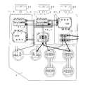
- the power conversion apparatus 1 of FIG. 6 has a semiconductor component for converting electric power necessary for the entire railway vehicle.
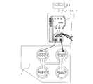
- the power conversion device 2 of FIG. 7 converts the power required for the entire railway vehicle by combining, for example, two functional modules 7_1 and 7_2.
- the inverter unit 11_1, the inverter unit 11_2, the converter unit 13_2, and the rectifier unit 15_1 are mounted on the heat receiving unit 43.
- Each of the inverter unit 11_1, the inverter unit 11_2, the converter unit 13_2, and the rectifier unit 15_1 is arranged at a predetermined distance in consideration of heat radiation from each semiconductor component. Therefore, the power conversion device 1 does not consider the optimization of dimensions.
- the power conversion device 2 in the case of being functional modules is configured by combining the functional module 7_1 and the functional module 7_2.
- the power conversion device 1 in the case where it is not functionalized, a large space is required because the power conversion units having semiconductor components are arranged without considering the size and the like. Yes.
- the power conversion unit in the power conversion device 2 in the case of being made into a functional module, since the power conversion unit is arranged in consideration of the size and the like, it can be arranged in a small space. .
- the inverter unit combined with the converter unit 13_2 selects the inverter unit 11_3 excluding the inverter unit 11_1 having the largest capacity among the plurality of inverter units 11_1 to 11_3, and constitutes the functional module 7_1.
- the functional module 7_2 can be configured by selecting the inverter unit 11_1 having the largest capacity among the plurality of inverter units 11_1 to 11_3.
- FIG. 2 shows the case where there are two inverter units, when there are three or more inverter units, it is desirable to configure the functional module 7_2 by selecting the inverter unit having the largest capacity or the second largest capacity. As a result, the heat generation amount and size of each functional module can be made substantially the same.
- FIG. 8 is a diagram showing an example of a heat generation distribution configuration in the case where the module is not functionalized in Embodiment 1 of the present invention.
- FIG. 9 is a diagram showing an example of a heat generation distribution configuration in the case where the functional module is formed in Embodiment 1 of the present invention.
- the area where the heat generation amount is high is smaller than the area where there is no heat generation amount.
- the area where the heat generation amount is high is larger than the area where there is no heat generation amount.
- the heat generation amount on the inverter unit 11_1 side is 5 to 10 W / cm 2
- the heat generation amount range on the inverter unit 11_2 side is 5 to 10 W / cm 2.
- the converter unit 13_2 to 15 sequentially into the surrounding range of calorific value from the center of the side 20W / cm 2, 10 ⁇ 15W / cm 2, 5 ⁇ 10W / cm 2 , and the range of the calorific value of the rectifier unit 15_1 side become the left center side and the right center side and at 15 ⁇ 20W / cm 2, 15 ⁇ 20W / 10 ⁇ 15W / cm 2 at the periphery of cm 2, 10 ⁇ 15W / cm 5 ⁇ 10W / cm 2 around the 2 Yes.
- the range of the calorific value on the inverter unit 11_2 side is 5 to 10 W / cm 2 and the calorific value on the converter unit 13_2 side.
- the range of the calorific value on the inverter unit 11_2 side is 5 to 10 W / cm 2 and the calorific value on the converter unit 13_2 side.
- the function module 7_2 around the inverter unit 11_1 10 ⁇ 15W / cm 2 in order to ambient range of calorific value from the center of the side, 5 ⁇ 10W / cm 2, and the range of the calorific value of the rectifier unit 15 _ side from the center In this order, it is 15 to 20 W / cm 2 , 10 to 15 W / cm 2 , and 5 to 10 W / cm 2 .
- FIG. 10 is a diagram illustrating an example of a temperature distribution configuration when the conventional functional module is not implemented.
- FIG. 11 is a diagram showing an example of a temperature distribution configuration in the case where the functional module is formed in the first embodiment of the present invention.
- the temperature tendency is not substantially the same, but as shown in FIG. 11, when the power converter 2 is functionalized, The temperature trends are almost the same.
- the temperature range of a region including the inverter unit 11_1, the inverter unit 11_2, a part of the rectifier unit 15_1, and a part of the converter unit 13_2. Is 150 to 200 ° C.
- the temperature range of a region including a part of the rectifier unit 15_1 and a part of the converter unit 13_2 is 200 to 250 ° C. That is, in this case, the temperature tendency is not the same.
- the temperature range of the region not including any power conversion unit is 100 to 150 ° C.
- the temperature range of the region including the inverter unit 11_2 is 0 to 100 ° C. on the functional module 7_1 side, and the temperature range of the region including the converter unit 13_2.
- the temperature ranges from 100 to 200 ° C. to 0 to 100 ° C., such as 100 to 200 ° C. and 0 to 100 ° C.
- the temperature range of the region including the inverter unit 11_1 ranges from 100 to 200 ° C. to 0 to 100 ° C., such as 100 to 200 ° C. and 0 to 100 ° C. on the center side.
- the temperature of the area including the rectifier unit 15_1 is in the temperature range from 100 to 200 ° C. to 0 to 100 ° C., such as 100 to 200 ° C. and 0 to 100 ° C. It is 0 ⁇ 100 °C. That is, in this case, the functional module 7_1 and the functional module 7_2 are in a state where the overall temperature tendency of the heat receiving unit 43 is substantially the same.
- the cooler 6 can efficiently conduct heat and dissipate heat, and the cooler 6 can be downsized. Further, electrically, the snubber circuit can be reduced in size and reduced, and the power converter 2 can be reduced in size and weight.
- the inverter units 11_1 to 11_4 and the converter unit 13_2 are alternately provided with power conversion units having different calorific values. Therefore, the power converter 2 can disperse the heat generated by the power conversion unit performed by the cooler 6. For this reason, the power conversion device 2 can efficiently cool each of the power conversion units having different calorific values provided for the functional modules 7_1 to 7_3. Moreover, since the power converter 2 only needs the cooling fan 23 of the same specification, the size of the cooler 6 can be minimized. Therefore, the power converter device 2 can promote reduction in size and weight of the device configuration.
- each functional module 7_1 to 7_3 is cooled by the cooler 6, the cooler 6 can be used effectively, so there is no need to provide a separate cooling mechanism, and the size of the cooler 6 is minimized.
- the semiconductor component can be effectively cooled.
- FIG. 12 is a diagram illustrating an example of a positional relationship between the functional modules 7_2 and 7_3 and the cooler 6 according to Embodiment 2 of the present invention.
- the power converter 5 in FIG. 12 includes a combination of a functional module 7_2 and a functional module 7_3.
- the cooler 6 is a heat sink, for example, and includes a heat radiating portion 41 and a heat receiving portion 43.
- the heat receiving part 43 is formed of a member having a flat surface, and each of the functional modules 7_2 and 7_3 described above is provided in contact with the heat receiving part 43, whereby electric power provided in each of the functional modules 7_2 and 7_3. Heat generated in the conversion unit is transmitted to the heat radiating unit 41 through the heat receiving unit 43.
- the heat radiating portion 41 includes a plurality of heat radiating fins 45.
- the heat radiating fins 45 are formed in the same wind direction as that of the cooling fan 23.
- the heat radiating part 41 radiates the heat transmitted through the heat receiving part 43 from the heat radiating fins 45.
- the functional module 7_2 and the functional module 7_3 are provided in the heat receiving unit 43 .
- a power conversion unit with a small calorific value for example, the inverter unit 11_4 is arranged at a position corresponding to the downstream side of the cooler 6, and a power conversion unit with a large calorific value, for example, the inverter unit 11_3 is a cooler 6 It arrange
- a power conversion unit with a small calorific value for example, the inverter unit 11_2 is arranged at a position corresponding to the downstream side of the cooler 6, and a power conversion unit with a large calorific value, for example, the converter unit 13_2 is a cooler 6 It arrange
- the cooler 6 is provided in the vertical direction, the heat receiving portion 43 is provided on the sealed chamber side, and the heat radiating portion 41 is provided on the open chamber side.
- outside air does not directly hit the electrical parts including the power conversion unit and the charging unit (not shown).
- the power conversion unit with a small calorific value is provided on the downstream side of the cooler 6, the power conversion unit with a large calorific value is provided on the upstream side of the cooler 6, and the cooler 6 is provided in the vertical direction, the cooling In the vessel 6, natural convection occurs, and the calorific value is balanced in each of the functional modules 7_2 and 7_3 so that the temperature distribution is kept in balance.
- the power conversion device 2 provides the heat receiving portion 43 at a position in contact with the sealed chamber 8 and the heat radiating portion 41 in the open chamber 9 communicating with the outside air.
- the power conversion device 2 does not directly apply external air to electrical components such as the power conversion unit and a charging unit (not shown).
- the power conversion device 2 can ensure the reliability of electrical components such as the power conversion unit.
- the power conversion device 2 is provided with, for example, a plurality of inverter units 11_2 to 11_4 and a converter unit 13_2 in the function modules 7_2 and 7_3, the heat generation of the power conversion unit performed by the cooler 6 is dispersed. Therefore, the power converter device 2 can reduce the temperature gradient of the heat receiving part 43 from a steep state to a gentle state.
- the power conversion device 2 is provided with the heat receiving portion 43 of the cooler 6 in which each of the power conversion units is mounted on the same plane in the vertical direction, and the power conversion unit with a small amount of heat generation is disposed on the downstream side of the cooler 6.
- the power conversion unit having a large calorific value is arranged upstream of the cooler 6. Therefore, in the heat receiving part 43 of the cooler 6, an air flow is formed in the vertical direction.
- the heat receiving part 43 heat with a small calorific value is generated on the downstream side of the cooler 6, and heat with a large calorific value is generated on the upstream side of the cooler 6, so that the temperature tendency of the heat receiving part 43 is almost the same. Keep the same. Since the cooling fan 23 is driven in this state, natural convection can be used, and the same flow of cooling air efficiently cools each power conversion unit having a different amount of heat generation. Further, the heat radiating fins 45 of the heat radiating portion 41 are formed in the same wind direction as that of the cooling fan 23. From the above, the overall cooling mechanism is simplified.
- the power conversion device 2 can provide the heat receiving portion 43 at a position in contact with the sealed chamber 8 and the heat radiating portion 41 in the open chamber 9 communicating with the outside air.
- the power conversion device 2 does not directly apply external air to electrical components such as the power conversion unit and a charging unit (not shown).
- the power conversion device 2 can ensure the reliability of electrical components such as the power conversion unit.
- the power converter 5 is configured by combining two functional modules 7_2 and 7_3 is illustrated.
- the number and types of functional modules are not limited to this, for example, 1 Two functional modules (see FIGS. 5A to 5C) may be combined, or two or more functional modules (see FIGS. 3A to 3C and FIGS. 4A to 4C) may be combined. Good.
- FIG. 13 is a diagram illustrating an example of a railway vehicle 51 on which the power conversion device 2 according to Embodiment 4 of the present invention is mounted.
- the railway vehicle 51 includes a pantograph 71, a transformer 72, an auxiliary power supply device 73, an air conditioning unit 74, and the like.
- the air conditioning unit 74 may be supplied with power from the auxiliary power supply device 73 via the power line 76, for example.
- the pantograph 71 Since the pantograph 71 is in contact with the overhead line 61, electricity is supplied from the overhead line 61 to the railway vehicle 51 via the pantograph 71.
- the overhead line 61 supplies electricity such as DC 600 V, DC 750 V, DC 1500 V, AC 20 kV, and AC 25 kV to the railway vehicle 51, for example. That is, the overhead line 61 is a main circuit that supplies high-voltage electricity, and various circuits and the like included in the railway vehicle 51 are auxiliary circuits that operate with low-voltage electricity. Therefore, the auxiliary power supply device 73 steps down the high voltage electricity supplied from the overhead wire 61 to the low voltage electricity and supplies it to the auxiliary circuit.
- the railway vehicle 51 is running with a DC voltage of 1500 V DC as a power source via the pantograph 71, for example.
- the railway vehicle 51 uses the power conversion device 2 to convert the DC voltage into a low-voltage DC voltage, for example, DC 600V class.
- the railway vehicle 51 supplies the AC voltage converted by the auxiliary power supply device 73, for example, a single-phase AC 400V class to the air conditioner 81.
- the railway vehicle 51 is running with an AC voltage of 25 kV as a power source.
- the railway vehicle 51 converts the AC voltage stepped down by the transformer 72, for example, a single-phase AC 400V class into a DC voltage, for example, a DC 600V class, using the power converter 2.
- the air conditioning unit 74 includes, for example, the power conversion device 2 and the air conditioner 81.
- the air conditioner 81 includes, for example, a heat exchanger 91, a compressor 92, an outdoor fan 93, and an indoor fan 94, and is connected by a refrigerant pipe (not shown) to form a refrigerant circuit. By circulating, a refrigeration cycle is formed.
- the power conversion device 2 includes a plurality of functional modules 7_1 to 7_3, a capacitor unit 4, a cooling fan 23, and the like.
- Each of the plurality of functional modules 7_1 to 7_3 is assigned to each load included in the air conditioner 81, and supplies AC power having different frequencies so as to be driven at different rotational speeds for each load.
- the power conversion units included in each of the plurality of functional modules 7_1 to 7_3 are allocated to loads included in the air conditioner 81, for example, the compressor 92, the outdoor fan 93, and the indoor fan 94, respectively.
- the power conversion unit to which the compressor 92 is assigned supplies AC power having different frequencies so as to be driven at a rotational speed corresponding to the compressor 92.
- the power conversion unit to which the outdoor blower 93 is assigned supplies AC power having different frequencies so as to be driven at a rotational speed corresponding to the outdoor blower 93.
- the power conversion unit to which the indoor blower 94 is assigned supplies AC power having a different frequency so as to be driven at a rotational speed corresponding to the indoor blower 94.
- each of the plurality of functional modules 7_1 to 7_3 is configured with a power conversion unit corresponding to a different load.
- one functional module 7_1 to 7 is used so that the heat generation amount is shared among the functional modules 7_1 to 7_3.
- the number and arrangement of power conversion units included in 7_3 are determined. Therefore, if there is one power conversion device 2, a plurality of power conversion units corresponding to different loads are provided, and heat dissipation in the power conversion device 2 and optimization of dimensions are improved. That is, originally, it is necessary to prepare different power sources for different loads, but a single power conversion device 2 shares the structural components of the power source.
- the power conversion device 2 supplies AC power having a different frequency for each different load. Therefore, for example, the structural components of the power conversion device 2 as a power source for driving the plurality of compressors 92, the outdoor fan 93, the plurality of indoor fans 94, and the like are shared. Therefore, the arrangement
- the arrangement configuration of the outdoor blower 93, the indoor blower 94, and the heat exchanger 91 is optimally designed, so that necessary cooling ability and heating ability can be obtained.
- the power conversion device 2 can prevent a decrease in reliability due to an increase in the number of components. .
- each of the plurality of functional modules 7_1 to 7_3 is assigned to each load included in the air conditioner 81, and supplies AC power having a different frequency for each load. To do.
- the power conversion device 2 shares, for example, the structural components of the power conversion device 2 as a power source for driving the plurality of compressors 92, the outdoor fan 93, the plurality of indoor fans 94, and the like. Can do.
- each functional module 7_1 to 7_3 is illustrated as having two power conversion units mounted, but one power conversion unit may be mounted, or 3 Two or more power conversion units may be mounted.
- a unit having a function of power conversion is mounted on the function modules 7_1 to 7_3, a unit for other uses such as a microcomputer may be mounted together with the power conversion unit.
- the cooler 6 is illustrated as being cooled by an air cooling method, any known technique such as a water cooling method can be used as long as it cools the functional modules 7_1 to 7_3. .
Landscapes
- Engineering & Computer Science (AREA)
- Power Engineering (AREA)
- Microelectronics & Electronic Packaging (AREA)
- Mechanical Engineering (AREA)
- Physics & Mathematics (AREA)
- Thermal Sciences (AREA)
- Life Sciences & Earth Sciences (AREA)
- Sustainable Development (AREA)
- Sustainable Energy (AREA)
- Transportation (AREA)
- Inverter Devices (AREA)
Abstract
Description
(実施の形態1の構成)
図1は、本発明の実施の形態1における電力変換装置における機能モジュールの配置構成の一例を示す図であり、図2は、本発明の実施の形態1における電力変換装置の機能構成の一例を示す図である。図1及び図2に示すように、電力変換装置2は、冷却ファンユニット21、コンデンサユニット4、電力変換器5を備えている。冷却ファンユニット21は、複数の冷却ファン23を備えている。電力変換器5は、収容部50に収容されており、収容部50に密閉室8及び開放室9が収容されている。密閉室8は、外部から密閉された空間である。開放室9は、外気と通ずる開口を備える空間である。開放室9には、冷却器6が配置される。密閉室8には、電力変換器5が配置されており、防塵、防水、特に鉄道車両のため鉄粉等が機能モジュールに混入して劣化することを防止する。
(実施の形態2の構成)
実施の形態2では、冷却器6の詳細構成について説明する。図12は、本発明の実施の形態2における機能モジュール7_2、7_3と冷却器6との位置関係の一例を示す図である。なお、図12の電力変換器5は、機能モジュール7_2及び機能モジュール7_3の組み合わせからなっている。図12に示すように、冷却器6は、例えばヒートシンクであって、放熱部41と、受熱部43とを備えている。受熱部43は、平面を有する部材で形成され、上記で説明した機能モジュール7_2、7_3のそれぞれが、受熱部43に接して設けられることで、機能モジュール7_2、7_3のそれぞれに設けられている電力変換ユニットで発生した熱が受熱部43を介して放熱部41に伝達される。放熱部41は、複数の放熱フィン45を備えている。放熱フィン45は、冷却ファン23の風向きと同一方向の風向きに形成されている。放熱部41は、受熱部43を介して伝達された熱を放熱フィン45から放熱する。
以上の説明から、電力変換装置2は、受熱部43を密閉室8と接する位置に設け、放熱部41を外気と通ずる開放室9に設ける。よって、電力変換装置2は、電力変換ユニット等の電気部品及び図示しない充電部に外気を直接当てさせない。この結果、電力変換装置2は、電力変換ユニット等の電気部品の信頼性を確保させることができる。
(実施の形態3の構成)
実施の形態3では、電力変換装置2が鉄道車両51に設けられた一例を説明する。図13は、本発明の実施の形態4における電力変換装置2が搭載される鉄道車両51の一例を示す図である。図13に示すように、鉄道車両51は、パンタグラフ71、トランス72、補助電源装置73、空調ユニット74等を備えている。なお、空調ユニット74には、例えば、電源線76を介して補助電源装置73から電力が供給されてもよい。
以上の説明から、電力変換装置2は、異なる負荷ごとに異なる周波数の交流電力を供給する。よって、例えば、複数台の圧縮機92、室外送風機93、及び複数台の室内送風機94等を駆動させる電源としての電力変換装置2の構造部品が共有化される。したがって、鉄道車両51に搭載される空気調和機81を構成する機器の配置制約が緩和される。
Claims (5)
- 鉄道車両に設けられる空気調和機に供給する電力変換装置であって、
半導体部品により構成され電力を変換するための電力変換ユニットが実装された機能モジュールを有する電力変換器を備え、
前記電力変換器は、
外部から供給される交流電圧を整流する整流器ユニットと直流電圧を交流電力へ変換するインバータユニットとが組み合わされた機能モジュール、交流電圧を直流電圧へ変換するコンバータユニットと前記コンバータユニットにより変換された直流電圧を交流電力へ変換するインバータユニットとが組み合わされた機能モジュール、直流電圧を交流電力へ変換するインバータユニットが設けられた機能モジュールのうち、いずれか1つ以上を備えたものであり、
前記機能モジュールは、前記半導体部品を冷却する冷却器を有する電力変換装置。 - 前記電力変換器は、
前記インバータユニットを前記空気調和機が有する機器に対応した台数分有する請求項1記載の電力変換装置。 - 前記電力変換器と前記冷却器とを収容する収容部をさらに備え、
前記収容部は、前記電力変換器を密閉する密閉室と、前記冷却器で放熱される熱を外気へ放熱させる開口を有する開放室とを有しており、
前記冷却器は、前記密閉室側に設けられ、前記複数の機能モジュールを受熱する受熱部と、前記開放室側に設けられ、前記受熱部で受熱した熱を放熱する放熱部と、を備え、
前記放熱部は、複数の放熱フィンを備え、
前記複数の放熱フィンの向きと、冷却ファンから前記複数の放熱フィンに送風される風向きとが同一方向に形成された請求項1又は2に記載の電力変換装置。 - 前記機能モジュールにおいて前記半導体部品を接続させる導体は、互いに対向する位置に設けられている請求項1~3の何れか一項に記載の電力変換装置。
- 電力を蓄えるコンデンサユニットとをさらに備え、
前記複数の機能モジュールは、
前記コンデンサユニットに取り外し自在に取り付けられている請求項1~4の何れか一項に記載の電力変換装置。
Priority Applications (4)
| Application Number | Priority Date | Filing Date | Title |
|---|---|---|---|
| JP2015551415A JP6169187B2 (ja) | 2013-12-03 | 2014-10-02 | 電力変換装置 |
| US15/027,000 US9998024B2 (en) | 2013-12-03 | 2014-10-02 | Power conversion apparatus |
| EP14867958.2A EP3079253B1 (en) | 2013-12-03 | 2014-10-02 | Power conversion device |
| CN201480066257.5A CN105981281B (zh) | 2013-12-03 | 2014-10-02 | 功率转换装置 |
Applications Claiming Priority (2)
| Application Number | Priority Date | Filing Date | Title |
|---|---|---|---|
| JP2013250347 | 2013-12-03 | ||
| JP2013-250347 | 2013-12-03 |
Publications (1)
| Publication Number | Publication Date |
|---|---|
| WO2015083427A1 true WO2015083427A1 (ja) | 2015-06-11 |
Family
ID=53273204
Family Applications (1)
| Application Number | Title | Priority Date | Filing Date |
|---|---|---|---|
| PCT/JP2014/076472 Ceased WO2015083427A1 (ja) | 2013-12-03 | 2014-10-02 | 電力変換装置 |
Country Status (5)
| Country | Link |
|---|---|
| US (1) | US9998024B2 (ja) |
| EP (1) | EP3079253B1 (ja) |
| JP (1) | JP6169187B2 (ja) |
| CN (1) | CN105981281B (ja) |
| WO (1) | WO2015083427A1 (ja) |
Cited By (2)
| Publication number | Priority date | Publication date | Assignee | Title |
|---|---|---|---|---|
| JP2016144283A (ja) * | 2015-01-30 | 2016-08-08 | 富士電機株式会社 | インバータ装置 |
| JP2019213306A (ja) * | 2018-06-01 | 2019-12-12 | 三菱電機株式会社 | 電力変換装置、鉄道車両空調装置、及び加温方法 |
Families Citing this family (6)
| Publication number | Priority date | Publication date | Assignee | Title |
|---|---|---|---|---|
| KR101720496B1 (ko) * | 2015-08-27 | 2017-04-10 | 엘지전자 주식회사 | 전력변환장치 및 이를 구비하는 공기조화기 |
| US10381147B2 (en) * | 2016-04-29 | 2019-08-13 | Siemens Aktiengesellschaft | Container arrangement for power transformers |
| US10069407B1 (en) * | 2017-03-02 | 2018-09-04 | Hewlett Packard Enterprise Development Lp | Converters to convert input voltages to output voltages |
| KR102299859B1 (ko) * | 2019-01-25 | 2021-09-08 | 엘에스일렉트릭 (주) | 인버터 장치 및 이를 포함하는 전력변환장치 |
| WO2021214951A1 (ja) * | 2020-04-23 | 2021-10-28 | 東芝三菱電機産業システム株式会社 | 電力変換装置 |
| CN222339048U (zh) * | 2024-01-19 | 2025-01-10 | 华为数字能源技术有限公司 | 充电装置 |
Citations (7)
| Publication number | Priority date | Publication date | Assignee | Title |
|---|---|---|---|---|
| JPH0678562A (ja) * | 1992-08-25 | 1994-03-18 | Fuji Electric Co Ltd | インバータ装置 |
| JPH11163545A (ja) * | 1997-12-01 | 1999-06-18 | Sanyo Denki Co Ltd | ユニット型電気機器制御装置及びモータ制御装置 |
| JP2003235112A (ja) | 2001-12-07 | 2003-08-22 | Toshiba Transport Eng Inc | 電力変換装置 |
| JP2004087711A (ja) * | 2002-08-26 | 2004-03-18 | Toshiba Corp | 強制風冷式電力変換装置 |
| JP2004328838A (ja) * | 2003-04-22 | 2004-11-18 | Fuji Electric Systems Co Ltd | 冷却装置および電気鉄道車両用補助電源装置 |
| WO2007138645A1 (ja) * | 2006-05-25 | 2007-12-06 | Mitsubishi Electric Corporation | 車両用補助電源装置 |
| JP2010129867A (ja) * | 2008-11-28 | 2010-06-10 | Mitsubishi Electric Corp | 電力用半導体装置 |
Family Cites Families (19)
| Publication number | Priority date | Publication date | Assignee | Title |
|---|---|---|---|---|
| JPS63174501A (ja) * | 1987-01-14 | 1988-07-19 | Toshiba Corp | 電気車の制御装置 |
| JP3563038B2 (ja) * | 2001-03-05 | 2004-09-08 | 東芝トランスポートエンジニアリング株式会社 | 電力変換装置 |
| JP3432505B1 (ja) * | 2002-02-26 | 2003-08-04 | 学校法人慶應義塾 | 電力変換器を用いたシステム |
| FI118661B (fi) * | 2002-10-17 | 2008-01-31 | Vacon Oyj | Jäähdytysjärjestely taajuusmuuttajassa |
| JP3822612B2 (ja) | 2004-03-15 | 2006-09-20 | 東芝トランスポートエンジニアリング株式会社 | 鉄道車両用電力変換装置 |
| US7113405B2 (en) * | 2004-05-27 | 2006-09-26 | Eaton Power Quality Corporation | Integrated power modules with a cooling passageway and methods for forming the same |
| CN1707932A (zh) * | 2004-06-08 | 2005-12-14 | 株式会社东芝 | 用于车辆的电源装置 |
| JP4127550B2 (ja) * | 2005-06-06 | 2008-07-30 | 三菱電機株式会社 | パワーユニット |
| CN101647186B (zh) * | 2007-04-27 | 2012-10-17 | 三菱电机株式会社 | 电力变换装置 |
| KR20100047314A (ko) * | 2007-09-21 | 2010-05-07 | 미쓰비시덴키 가부시키가이샤 | 전기차용 전력 변환 장치 |
| WO2009101673A1 (ja) * | 2008-02-13 | 2009-08-20 | Mitsubishi Electric Corporation | 電力変換装置 |
| JP4978507B2 (ja) | 2008-02-20 | 2012-07-18 | 三菱電機株式会社 | 車両用制御装置 |
| BRPI0823126A2 (pt) | 2008-10-10 | 2015-06-16 | Mitsubishi Electric Corp | Dispositivo de controle de veículo. |
| CN101459375B (zh) * | 2009-01-09 | 2011-05-25 | 铁道部运输局 | 牵引变流装置 |
| DE102009053583B3 (de) * | 2009-11-17 | 2011-03-31 | Semikron Elektronik Gmbh & Co. Kg | Modular aufgebaute Stromrichteranordnung |
| JP5777412B2 (ja) * | 2011-06-03 | 2015-09-09 | 三菱電機株式会社 | 多電源式鉄道車両用の空調電源システム |
| JP5749192B2 (ja) | 2012-02-13 | 2015-07-15 | 株式会社東芝 | 車両用駆動制御装置 |
| CN103368413A (zh) * | 2013-07-04 | 2013-10-23 | 株洲南车时代电气股份有限公司 | 一种高集成变流装置 |
| US9398723B2 (en) * | 2013-08-29 | 2016-07-19 | Eaton Corporation | Apparatus and methods using heat pipes for linking electronic assemblies that unequally produce heat |
-
2014
- 2014-10-02 EP EP14867958.2A patent/EP3079253B1/en active Active
- 2014-10-02 JP JP2015551415A patent/JP6169187B2/ja active Active
- 2014-10-02 CN CN201480066257.5A patent/CN105981281B/zh active Active
- 2014-10-02 US US15/027,000 patent/US9998024B2/en active Active
- 2014-10-02 WO PCT/JP2014/076472 patent/WO2015083427A1/ja not_active Ceased
Patent Citations (7)
| Publication number | Priority date | Publication date | Assignee | Title |
|---|---|---|---|---|
| JPH0678562A (ja) * | 1992-08-25 | 1994-03-18 | Fuji Electric Co Ltd | インバータ装置 |
| JPH11163545A (ja) * | 1997-12-01 | 1999-06-18 | Sanyo Denki Co Ltd | ユニット型電気機器制御装置及びモータ制御装置 |
| JP2003235112A (ja) | 2001-12-07 | 2003-08-22 | Toshiba Transport Eng Inc | 電力変換装置 |
| JP2004087711A (ja) * | 2002-08-26 | 2004-03-18 | Toshiba Corp | 強制風冷式電力変換装置 |
| JP2004328838A (ja) * | 2003-04-22 | 2004-11-18 | Fuji Electric Systems Co Ltd | 冷却装置および電気鉄道車両用補助電源装置 |
| WO2007138645A1 (ja) * | 2006-05-25 | 2007-12-06 | Mitsubishi Electric Corporation | 車両用補助電源装置 |
| JP2010129867A (ja) * | 2008-11-28 | 2010-06-10 | Mitsubishi Electric Corp | 電力用半導体装置 |
Cited By (3)
| Publication number | Priority date | Publication date | Assignee | Title |
|---|---|---|---|---|
| JP2016144283A (ja) * | 2015-01-30 | 2016-08-08 | 富士電機株式会社 | インバータ装置 |
| JP2019213306A (ja) * | 2018-06-01 | 2019-12-12 | 三菱電機株式会社 | 電力変換装置、鉄道車両空調装置、及び加温方法 |
| JP7072445B2 (ja) | 2018-06-01 | 2022-05-20 | 三菱電機株式会社 | 電力変換装置、鉄道車両空調装置、及び加温方法 |
Also Published As
| Publication number | Publication date |
|---|---|
| US9998024B2 (en) | 2018-06-12 |
| JP6169187B2 (ja) | 2017-07-26 |
| CN105981281B (zh) | 2018-12-07 |
| US20160241156A1 (en) | 2016-08-18 |
| EP3079253B1 (en) | 2020-03-25 |
| JPWO2015083427A1 (ja) | 2017-03-16 |
| EP3079253A1 (en) | 2016-10-12 |
| CN105981281A (zh) | 2016-09-28 |
| EP3079253A4 (en) | 2017-09-06 |
Similar Documents
| Publication | Publication Date | Title |
|---|---|---|
| JP6169187B2 (ja) | 電力変換装置 | |
| CN101834560B (zh) | 用于电动机控制器的装置 | |
| EP3039954B1 (en) | Apparatus and methods using heat pipes for linking electronic assemblies that unequally produce heat | |
| EP3468025B1 (en) | Power conversion device | |
| JP5271487B2 (ja) | 電力変換装置 | |
| US10453770B2 (en) | Power converter and power converter for railroad vehicle | |
| JP2014114982A (ja) | 圧縮機ユニット及び冷凍サイクル装置 | |
| JP6804543B2 (ja) | 電力変換装置、冷却構造、電力変換システム及び電源装置 | |
| EP3661042A1 (en) | Electric-power conversion device | |
| JP2014220334A (ja) | 電力変換装置 | |
| JPWO2018087893A1 (ja) | 電力変換装置及びこれを用いた空気調和装置 | |
| CN205678790U (zh) | 一种变频空调室外机电路板散热装置及电控盒 | |
| TW201601423A (zh) | 電力變換裝置及車輛用控制裝置 | |
| WO2022264301A1 (ja) | 電子機器 | |
| JP7520259B2 (ja) | 電子機器 | |
| JP2024046046A (ja) | 半導体装置 | |
| JP5404310B2 (ja) | 電源装置 | |
| JP2006149199A (ja) | 鉄道車両用電力変換装置 | |
| JP7209898B2 (ja) | 電力変換装置、モータ駆動制御装置、送風機、圧縮機および空気調和機 | |
| JP2016068900A (ja) | 電力変換装置および冷却装置 | |
| JP6281595B2 (ja) | 圧縮機システム | |
| US7480142B2 (en) | Boost spring holder for securing a power device to a heatsink | |
| JP2024125529A (ja) | 半導体装置 | |
| US20230052725A1 (en) | Converter | |
| JP2017204910A (ja) | 圧縮機システム |
Legal Events
| Date | Code | Title | Description |
|---|---|---|---|
| 121 | Ep: the epo has been informed by wipo that ep was designated in this application |
Ref document number: 14867958 Country of ref document: EP Kind code of ref document: A1 |
|
| ENP | Entry into the national phase |
Ref document number: 2015551415 Country of ref document: JP Kind code of ref document: A |
|
| WWE | Wipo information: entry into national phase |
Ref document number: 15027000 Country of ref document: US |
|
| REEP | Request for entry into the european phase |
Ref document number: 2014867958 Country of ref document: EP |
|
| WWE | Wipo information: entry into national phase |
Ref document number: 2014867958 Country of ref document: EP |
|
| NENP | Non-entry into the national phase |
Ref country code: DE |