WO2015083625A1 - クランプ装置 - Google Patents
クランプ装置 Download PDFInfo
- Publication number
- WO2015083625A1 WO2015083625A1 PCT/JP2014/081467 JP2014081467W WO2015083625A1 WO 2015083625 A1 WO2015083625 A1 WO 2015083625A1 JP 2014081467 W JP2014081467 W JP 2014081467W WO 2015083625 A1 WO2015083625 A1 WO 2015083625A1
- Authority
- WO
- WIPO (PCT)
- Prior art keywords
- clamp
- rod
- lock members
- piston rod
- clamp device
- Prior art date
- Legal status (The legal status is an assumption and is not a legal conclusion. Google has not performed a legal analysis and makes no representation as to the accuracy of the status listed.)
- Ceased
Links
Images


Classifications
-
- B—PERFORMING OPERATIONS; TRANSPORTING
- B25—HAND TOOLS; PORTABLE POWER-DRIVEN TOOLS; MANIPULATORS
- B25B—TOOLS OR BENCH DEVICES NOT OTHERWISE PROVIDED FOR, FOR FASTENING, CONNECTING, DISENGAGING OR HOLDING
- B25B5/00—Clamps
- B25B5/06—Arrangements for positively actuating jaws
- B25B5/061—Arrangements for positively actuating jaws with fluid drive
-
- B—PERFORMING OPERATIONS; TRANSPORTING
- B23—MACHINE TOOLS; METAL-WORKING NOT OTHERWISE PROVIDED FOR
- B23B—TURNING; BORING
- B23B31/00—Chucks; Expansion mandrels; Adaptations thereof for remote control
- B23B31/40—Expansion mandrels
- B23B31/404—Gripping the work or tool by jaws moving radially controlled by conical surfaces
- B23B31/4053—Gripping the work or tool by jaws moving radially controlled by conical surfaces using fluid-pressure means to actuate the gripping means
-
- B—PERFORMING OPERATIONS; TRANSPORTING
- B23—MACHINE TOOLS; METAL-WORKING NOT OTHERWISE PROVIDED FOR
- B23Q—DETAILS, COMPONENTS, OR ACCESSORIES FOR MACHINE TOOLS, e.g. ARRANGEMENTS FOR COPYING OR CONTROLLING; MACHINE TOOLS IN GENERAL CHARACTERISED BY THE CONSTRUCTION OF PARTICULAR DETAILS OR COMPONENTS; COMBINATIONS OR ASSOCIATIONS OF METAL-WORKING MACHINES, NOT DIRECTED TO A PARTICULAR RESULT
- B23Q1/00—Members which are comprised in the general build-up of a form of machine, particularly relatively large fixed members
- B23Q1/0063—Connecting non-slidable parts of machine tools to each other
- B23Q1/0081—Connecting non-slidable parts of machine tools to each other using an expanding clamping member insertable in a receiving hole
-
- B—PERFORMING OPERATIONS; TRANSPORTING
- B23—MACHINE TOOLS; METAL-WORKING NOT OTHERWISE PROVIDED FOR
- B23Q—DETAILS, COMPONENTS, OR ACCESSORIES FOR MACHINE TOOLS, e.g. ARRANGEMENTS FOR COPYING OR CONTROLLING; MACHINE TOOLS IN GENERAL CHARACTERISED BY THE CONSTRUCTION OF PARTICULAR DETAILS OR COMPONENTS; COMBINATIONS OR ASSOCIATIONS OF METAL-WORKING MACHINES, NOT DIRECTED TO A PARTICULAR RESULT
- B23Q3/00—Devices holding, supporting, or positioning work or tools, of a kind normally removable from the machine
- B23Q3/02—Devices holding, supporting, or positioning work or tools, of a kind normally removable from the machine for mounting on a work-table, tool-slide, or analogous part
- B23Q3/06—Work-clamping means
- B23Q3/08—Work-clamping means other than mechanically-actuated
- B23Q3/082—Work-clamping means other than mechanically-actuated hydraulically actuated
-
- B—PERFORMING OPERATIONS; TRANSPORTING
- B25—HAND TOOLS; PORTABLE POWER-DRIVEN TOOLS; MANIPULATORS
- B25B—TOOLS OR BENCH DEVICES NOT OTHERWISE PROVIDED FOR, FOR FASTENING, CONNECTING, DISENGAGING OR HOLDING
- B25B11/00—Work holders not covered by any preceding group in the subclass, e.g. magnetic work holders, vacuum work holders
-
- B—PERFORMING OPERATIONS; TRANSPORTING
- B25—HAND TOOLS; PORTABLE POWER-DRIVEN TOOLS; MANIPULATORS
- B25B—TOOLS OR BENCH DEVICES NOT OTHERWISE PROVIDED FOR, FOR FASTENING, CONNECTING, DISENGAGING OR HOLDING
- B25B5/00—Clamps
- B25B5/14—Clamps for work of special profile
-
- B—PERFORMING OPERATIONS; TRANSPORTING
- B25—HAND TOOLS; PORTABLE POWER-DRIVEN TOOLS; MANIPULATORS
- B25B—TOOLS OR BENCH DEVICES NOT OTHERWISE PROVIDED FOR, FOR FASTENING, CONNECTING, DISENGAGING OR HOLDING
- B25B5/00—Clamps
- B25B5/16—Details, e.g. jaws, jaw attachments
Definitions
- the present invention relates to a clamp apparatus, and more particularly, to an apparatus for clamping an object to be clamped using a hole formed in the object to be clamped such as a work or a mold.
- Patent Document 1 Japanese Patent Application Laid-Open No. 2010-36314
- the prior art is configured as follows.
- the four locking members (grippers) to be inserted into the holes of the object to be clamped are annularly arranged in the circumferential direction.
- a wedge surface provided on the upper portion of the clamp rod is engaged with the inclined surface provided on the inner periphery of the upper half portion of each lock member from the upper side. Further, the inner peripheral surface of the lower half portion of the lock member is in contact with the outer peripheral surface of the lower portion of the clamp rod.
- the lock member is moved radially outward so that the lock member is in close contact with the inner peripheral surface of the hole, and subsequently, via the lock member in the close contact state and the inner peripheral surface of the hole
- the clamp target is pulled down to fix the clamp target on the seating surface.
- An object of the present invention is to provide a clamp device capable of fixing a clamp target having a small hole diameter.
- the present invention is configured as follows, for example, as shown in FIGS. 1A to 3B.
- a pair of lock members 22, 22 which are projected to the tip side of the housing 1 and inserted into the holes of the object to be clamped are disposed so as to be pressable on both sides of the inner peripheral surface of the holes.
- An advancing means 38 is provided for pushing the lock members 22, 22 to the tip side with a predetermined force.
- the wedge surface 33 of the clamp rod 32 is engaged with the lock member 22 from the tip end side.
- the clamp rod 32 is clamped and driven to the proximal side by the drive means D and unclamped to the distal side.
- the base members of the inner peripheries of the lock members 22 in the unclamped position can contact or approach the outer peripheral surface of the clamp rod 32 on the base end side of the wedge surfaces 33, 33.
- Recesses 50, 50 for receiving 22, 22 are formed.
- the present invention has the following effects.
- a pair of lock members inserted into the hole of the object to be clamped and pressed against both sides of the inner peripheral surface of the hole are provided, and a recess for receiving the base of the inner periphery of the lock member in the unclamped position
- the base of the inner periphery of the pair of lock members is formed on the outer surface of the clamp rod on the base end side of the wedge surface so that the bases of the inner circumferences of the pair of lock members can contact or approach.
- the outer diameter dimension of the member is significantly reduced. For this reason, the clamp apparatus which can fix the clamp target object with a small hole diameter was able to be provided.
- the concave portions 50 are communicated with each other in the clamp rod 32.
- the recess can be formed deep, the outer diameter of the pair of lock members at the unclamped position is further reduced. For this reason, the clamp device can fix a clamp target having a smaller hole diameter.
- the inclination angle of the wedge surface 33 with respect to the axial center of the clamp rod 32 is preferably set in the range of 10 degrees to 40 degrees, and set in the range of 15 degrees to 25 degrees. More preferable. Further, by setting the inclination angle of the wedge surface to a relatively large value, the amount of movement of the lock member in the radial direction can be increased, so it is possible to provide a clamp device having a large allowable range of the hole diameter of the object to be clamped. As a result, it is possible to share a small hole diameter clamping target object and a large hole diameter clamping target object by one clamping device.
- the drive means D has a piston 7 inserted into the housing 1 and a piston rod 8 protruding from the piston 7 in the distal direction. Further, the advancing means 38 is inserted into an annular space between the housing 1 and the piston rod 8 to support the lock members 22 and 22 from the base end side, and a support cylinder 39 and the support cylinder 39. And a spring 40 biased in the distal direction.
- a connecting cylinder 42 connecting the piston rod 8 and the clamp rod 32 is inserted into an annular space between the support cylinder 39 and the piston rod 8, and the connecting cylinder 42 and the piston rod 8 are radiused. It fixes by the connecting pin 43 extended in the direction.
- connection pin 43 Both end portions of the connection pin 43 are inserted into pin holes 47 formed in the peripheral wall of the support cylinder 39.
- the proximal end wall of each pin hole 47 limits the movement of the piston rod 8 in the proximal direction by more than a predetermined amount relative to the support cylinder 39.
- connection pin is received by the lower wall of the pin hole.
- the piston rod is prevented from lowering below the predetermined amount with respect to the support cylinder.
- a guide member 16 is provided which protrudes to the distal end side of the housing 1 and a peripheral wall 18 of the guide member 16 is configured to be insertable into the hole of the object to be clamped.
- the guide groove 21 penetrates the peripheral wall 18 of the guide member 16 and the guide groove 21 supports the lock member 22 so as to be movable in the radial direction.
- the support cylinder 39 is configured to receive the lock member 22 from the proximal end side via the guide member 16. In this case, the lock member can be smoothly inserted into the hole of the object to be clamped via the guide member.
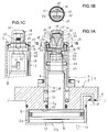
- FIG. 1A shows an embodiment of the present invention and is an elevational cross-sectional view of an unclamped state of a clamping device.
- FIG. 1B is a cross-sectional view taken along line 1B-1B in FIG. 1A.
- FIG. 1C is a partial cross-sectional view of the left side view of FIG. 1A described above.
- FIG. 2 is an enlarged perspective view of a clamp rod provided in the clamp device.
- FIG. 3A shows an empty clamping state of the clamping device and is a partial view similar to FIG. 1A.
- FIG. 3B is a cross-sectional view taken along line 3B-3B in FIG. 3A.
- FIGS. 1A to 3B show an embodiment of the present invention.
- the clamp device of this embodiment is used to clamp a workpiece as a clamp target.
- the configuration of the clamp device will be described with reference to FIGS. 1A to 1C and FIG.
- the housing 1 is attached to a fixed base T such as a table.
- the housing 1 includes a lower housing 2 fixed to a fixing base T by a plurality of bolts (not shown), and a cylindrical upper housing 3 mounted on the upper surface of the lower housing 2.
- the lower housing 2 and the upper housing 3 are fastened by a plurality of bolts 4.
- a large diameter cylinder hole 2a, a small diameter hole 2b and a medium diameter hole 2c are formed in order from the bottom.
- a seating surface 5 is provided which receives a work (not shown) as a clamp target.
- the piston 7 is inserted into the cylinder hole 2a in a sealed manner, and the piston rod 8 protruding upward from the piston 7 is inserted into the small diameter hole 2b in a sealed manner.
- Compressed air is supplied and discharged to the clamp chamber 10 formed on the upper side of the piston 7 through the supply and discharge port 11. Further, compressed air is supplied and discharged to the unclamping chamber 12 formed on the lower side of the piston 7 through another supply and discharge port 13.
- the piston 7, the piston rod 8, the clamp chamber 10 and the unclamp chamber 12 constitute a drive means D for the clamp rod 32, which will be described later.
- the guide member 16 is inserted into the upper part of the upper housing 3 so as to be movable in the vertical direction (axial direction).
- the guide member 16 comprises a top wall 17 and a peripheral wall 18 integrally formed without joints.
- the guide member 16 is protruded to the upper side (tip end side) than the upper end (tip end) of the upper housing 3 and can be inserted into a hole (not shown) of a workpiece as a clamping target.
- a flange portion 19 protrudes radially outward from the lower portion of the peripheral wall 18, and the flange portion 19 is inserted in the upper portion of the upper housing 3 so as to be movable in the radial direction (horizontal direction).
- a pair of guide grooves 21 pass through the peripheral wall 18 face to face.
- the lock member 22 is movably inserted in each guide groove 21 in the radial direction (horizontal direction).
- the lock member 22 includes an engaging portion 23 pressed against the inner peripheral surface of the hole of the work and a base portion 24 formed on the lower side of the engaging portion 23. The lower surface of the base portion 24 is supported by the upper surface of the flange portion 19.
- a mounting groove 25 is formed on the outer peripheral surface of the base portion 24 in the circumferential direction.
- an elastic body 29 which is thin and formed in a band shape by rubber or synthetic resin is mounted on the mounting grooves 25 and 25 and the outer peripheral surface of the guide member 16, an elastic body 29 which is thin and formed in a band shape by rubber or synthetic resin is mounted. Thereby, the elastic body 29 biases the lock member 22 radially inward. That is, the elastic body 29 constitutes a return means of the lock members 22.
- a dust seal 30 is disposed between the upper portion of the inner peripheral surface of the upper housing 3 and the base portion 24.
- the dust seal 30 is made of synthetic resin or the like, and the inner peripheral portion thereof is in contact with the outer peripheral surface of the elastic body 29.
- the dust seal 30 biases the lock member 22 and the guide member 16 radially inward.
- the clamp rod 32 can be inserted into the guide member 16 from the lower side (proximal side). Further, the wedge surface 33 provided on the upper portion of the clamp rod 32 is engaged with the inclined surface 35 formed on the inner side surface of each of the lock members 22 from the upper side.
- the wedge surface 33 and the inclined surface 35 are inclined so as to approach the axial center of the clamp rod 32 as it goes downward, and in this case, are configured by a plane.
- the inclination angle of the wedge surface 33 with respect to the axial center of the clamp rod 32 is set in a range of about 18 degrees to about 22 degrees here, it is preferable to set in a range of 15 degrees to 25 degrees. It may be set within the range of 10 degrees to 40 degrees.
- An advancing means 38 is provided to push the guide member 16 upward with a predetermined force.
- the advancing means 38 is inserted into the annular space between the housing 1 and the piston rod 8 to receive the lock member 22 from the lower side (proximal end side), the support cylinder 39 and the support cylinder 39 upward.
- a spring 40 for biasing is provided.
- the support cylinder 39 receives the lock member 22 from the lower side via the guide member 16.
- a connecting cylinder 42 connecting the piston rod 8 and the clamp rod 32 is inserted into an annular space between the support cylinder 39 and the piston rod 8.
- the connecting cylinder 42 and the piston rod 8 are fixed by a connecting pin 43 extending in the radial direction (horizontal direction).
- the lower flange 45 of the clamp rod 32 is movably supported in the radial direction (horizontal direction) between the upper end portion of the connecting cylinder 42 and the upper end surface of the piston rod 8.
- both end portions of the connection pin 43 are inserted into pin holes 47 formed in the peripheral wall of the support cylinder 39.
- the lower wall (proximal end wall) of each pin hole 47 limits the movement of the piston rod 8 downward (in the proximal direction) by more than a predetermined amount with respect to the support cylinder 39.
- a through hole 49 is formed in the clamp rod 32 below the wedge surface 33 in a direction substantially orthogonal to the axial center of the clamp rod 32.
- a pair of recessed parts 50 and 50 (refer FIG. 2 and FIG. 3A) are formed in the both sides of the through-hole 49 by the outer peripheral surface of the clamp rod 32. As shown in FIG. That is, here, the pair of concave portions 50, 50 communicate with each other.
- the base of the inner periphery of the lock member 22 in the unclamped position is accommodated in the recess 50, and the lower portions of the inner peripheries of the lock members 22 are in contact. In place of such contact, the lower portions of the inner circumferences of the lock members 22 may be approached with a predetermined gap.
- the clamp device operates as follows. In the unclamped state of FIGS. 1A to 1C, the compressed air of the clamp chamber 10 is discharged and the unclamped chamber 12 is supplied with the compressed air. Thereby, the piston 7 moves the clamp rod 32 to the upper unclamping position, the spring 40 moves the guide member 16 and the locking member 22 to the upper unclamping position through the support cylinder 39, and each lock member 22 By the biasing force of the elastic body 29, it is largely retracted inward in the radial direction. Therefore, the outer peripheral surface of the engagement portion 23 of the lock member 22 is retracted inward relative to the outer peripheral surface of the peripheral wall 18 of the guide member 16. Further, lower portions of the inner circumferences of the pair of lock members 22 come into contact with each other. Thus, the guide member 16 can prevent the peripheral wall (not shown) of the hole of the workpiece from colliding with the lock member 22 at the time of loading the workpiece described below.
- the hole of the work is externally fitted with a predetermined gap between the peripheral wall 18 of the guide member 16 and the engaging portion 23 of the lock member 22 and the lower surface of the work is It is received by the seating surface 5 of the upper housing 3.
- connection is performed.
- the pin 43 is received by the lower wall of the pin hole 47.
- the piston rod 8 is prevented from being lowered relative to the support cylinder 39 by more than a predetermined amount.
- the dust seal 30 can be prevented from being excessively compressed by the lock member 22.
- the empty clamp state the lower end of the piston 7 is received by the bottom wall 12a (see FIG. 1A) of the unclamp chamber 12, so that the piston 7 and the support cylinder 39 are prevented from being excessively lowered. Ru.
- the above embodiment provides the following advantages.
- the inclination angle of the wedge surface 33 with respect to the axial center of the clamp rod 32 is set within a range of 10 degrees to 40 degrees, and the base of the inner periphery of the lock member 22 in the unclamped position is accommodated in the recess 50.
- the amount of radial movement of the member 22 can be increased.
- permissible_range of the hole diameter of a clamp object can be enlarged.
- the clamp device of the present invention can cope with a plurality of works of a work having a small diameter hole (clamp target) and another work having a large diameter hole. That is, it becomes possible to fix a work having a small diameter hole and another work having a large diameter hole by one clamp device.
- the above embodiment can be modified as follows.
- the pressure fluid used for the drive means D may be a liquid such as pressure oil instead of compressed air.
- a single-acting type such as a spring release type or a spring lock type may be adopted.
- the drive means D may be another type of actuator such as a motor instead of the fluid pressure actuator.
- the pair of concave portions 50, 50 may be formed on the outer peripheral surface of the clamp rod 32, but it is not essential to communicate.
- the guide member 16 may be omitted to expose the lock member 22 to the external space.
Landscapes
- Engineering & Computer Science (AREA)
- Mechanical Engineering (AREA)
- Jigs For Machine Tools (AREA)
Abstract
Description
クランプ対象物の孔に挿入される4つのロック部材(グリッパー)を周方向へ環状に配置する。各ロック部材の上半部分の内周に設けた傾斜面に、クランプロッドの上部に設けた楔面が、上側から係合される。また、当該クランプロッドの下部の外周面には、前記ロック部材の下半部分の内周面が接当される。
クランプ駆動時には、前記ロック部材を所定の力によって上方位置に保持し、その状態で前記クランプロッドを下方へ駆動する。すると、まず、前記ロック部材が半径方向の外方へ移動して当該ロック部材が前記孔の内周面に密着し、引き続いて、その密着状態のロック部材と前記孔の内周面とを介してクランプ対象物を引き下げて、当該クランプ対象物を着座面に固定する。
本発明の目的は、孔径が小さいクランプ対象物を固定できるクランプ装置を提供することにある。
ハウジング1よりも先端側へ突出されてクランプ対象物の孔に挿入される一対のロック部材22,22を、前記孔の内周面の両側部に押付け可能に配置する。前記のロック部材22,22を所定の力で先端側へ押す進出手段38が設けられる。前記各ロック部材22にクランプロッド32の楔面33を先端側から係合させる。前記クランプロッド32を駆動手段Dによって基端側へクランプ駆動すると共に先端側へアンクランプ駆動する。そして、前記楔面33,33の基端側で前記クランプロッド32の外周面に、アンクランプ位置の前記ロック部材22,22の内周の基部同士が接触可能または接近可能なように当該ロック部材22,22を収容する凹部50,50が形成される。
クランプ対象物の孔に挿入されて当該孔の内周面の両側部に押付けられる一対のロック部材を設け、アンクランプ位置の上記ロック部材の内周の基部を収容する凹部を、前記クランプロッドの楔面の基端側で当該クランプロッドの外周面に形成して、上記一対のロック部材の内周の基部同士が接触可能または接近可能なように構成したので、上記アンクランプ位置の一対のロック部材の外径寸法が大幅に小さくなる。
このため、孔径が小さいクランプ対象物を固定できるクランプ装置を提供できた。
この場合、前記凹部を深く形成することが可能になるので、前記アンクランプ位置の一対のロック部材の外径寸法がさらに小さくなる。このため、クランプ装置は、孔径がさらに小さいクランプ対象物を固定できる。
そして、上記楔面の傾斜角度を比較的に大きい値に設定することにより、ロック部材の半径方向の移動量を大きくできるので、クランプ対象物の孔径の許容範囲が大きいクランプ装置を提供できる。これにより、小さい孔径のクランプ対象物と大きい孔径のクランプ対象物とを一つのクランプ装置で共用できる。
前記駆動手段Dは、前記ハウジング1に挿入されたピストン7とそのピストン7から先端方向へ突出されたピストンロッド8とを有する。また、前記進出手段38は、前記ハウジング1と前記ピストンロッド8との間の環状空間に挿入されて前記ロック部材22,22を基端側から受け止め可能な支持筒39と、その支持筒39を先端方向へ付勢するバネ40とを備える。前記支持筒39と前記ピストンロッド8との間の環状空間に、そのピストンロッド8と前記クランプロッド32とを接続する連結筒42を挿入すると共に、その連結筒42と前記ピストンロッド8とを半径方向へ延びる連結ピン43で固定する。前記連結ピン43の両端部を、前記支持筒39の周壁に形成したピン孔47,47に挿入する。各ピン孔47の基端壁は、前記支持筒39に対して前記ピストンロッド8が所定量を越えて基端方向へ移動するのを制限する。
前記ハウジング1よりも先端側へ突出されるガイド部材16を設け、そのガイド部材16の周壁18を前記クランプ対象物の前記孔に挿入可能に構成する。上記ガイド部材16の周壁18にガイド溝21を貫通させ、そのガイド溝21が前記ロック部材22を半径方向へ移動可能に支持する。そして、前記支持筒39が前記ガイド部材16を介して前記ロック部材22を基端側から受け止めるように構成する。
この場合、前記クランプ対象物の孔にガイド部材を介してロック部材を円滑に挿入できる。
上記ピストン7とピストンロッド8とクランプ室10とアンクランプ室12とが、後述するクランプロッド32の駆動手段Dを構成している。
上記周壁18の下部からフランジ部19が半径方向の外方へ突出され、そのフランジ部19が上ハウジング3の上部に半径方向(水平方向)へ移動可能に挿入される。
上記ロック部材22は、ワークの前記孔の内周面に押付けられる係合部23と、その係合部23よりも下側に形成されたベース部24とによって構成される。そのベース部24の下面が前記フランジ部19の上面に支持される。
なお、上記クランプロッド32の軸心に対する楔面33の傾斜角度は、ここでは約18度から約22度の範囲に設定しているが、15度から25度の範囲内に設定することが好ましく、10度から40度の範囲内に設定してもよい。
さらに、前記楔面33の下側でクランプロッド32には、そのクランプロッド32の軸心とほぼ直交する方向へ貫通孔49が形成される。これにより、クランプロッド32の外周面で貫通孔49の両側部に、一対の凹部50,50(図2と図3Aを参照)が形成される。即ち、ここでは、上記一対の凹部50,50同士が連通されている。
図1Aのアンクランプ状態では、上記凹部50に、アンクランプ位置の前記ロック部材22の内周の基部が収容され、上記ロック部材22,22の内周の下部同士が接触されている。なお、このように接触させることに代えて、ロック部材22,22の内周の下部同士が所定の隙間をあけて接近するようにしてもよい。
図1Aから図1Cのアンクランプ状態では、クランプ室10の圧縮空気が排出されると共にアンクランプ室12に圧縮空気が供給されている。これにより、ピストン7がクランプロッド32を上方のアンクランプ位置へ移動させ、バネ40が支持筒39を介してガイド部材16及びロック部材22を上方のアンクランプ位置へ移動させ、各ロック部材22が弾性体29の付勢力によって半径方向の内方へ大きく後退される。
このため、ロック部材22の係合部23の外周面が、ガイド部材16の周壁18の外周面よりも内方に後退される。また、上記一対のロック部材22,22の内周の下部同士が接触される。これにより、下記のワーク搬入時に、ワークの孔の周壁(いずれも図示せず)がロック部材22に衝突するのを上記ガイド部材16によって防止できる。
すると、まず、バネ40の付勢力によって上昇位置に保持されたガイド部材16及びロック部材22に対してクランプロッド32が下降していき、そのクランプロッド32の楔面33がロック部材22を半径方向の外方へ押し出し、各ロック部材22の係合部23がワークの孔(いずれも図示せず)の内周面を塑性変形させたり当該内周面に摩擦接当したりすることにより、上記孔に係合する。次いで、その係合状態で、バネ40の付勢力に抗してクランプロッド32がロック部材22及びガイド部材16を下向きにロック駆動する。これにより、上記ロック部材22がワークを下向きに引っ張り、そのワークの下面が上ハウジング3の着座面5に強力に固定される。
なお、上記空クランプ状態においては、ピストン7の下端が前記アンクランプ室12の底壁12a(図1Aを参照)に受け止められるので、そのピストン7及び支持筒39が過度に下降することが防止される。
クランプロッド32の軸心に対する楔面33の傾斜角度を10度から40度の範囲内に設定すると共に、アンクランプ位置のロック部材22の内周の基部を前記凹部50に収容したので、そのロック部材22の半径方向の移動量を大きくできる。これにより、クランプ対象物の孔径の許容範囲を大きくできる。その結果、本発明のクランプ装置は、小径孔を有するワーク(クランプ対象物)と大径孔を有する別のワークとの複数のワークに対応できる。即ち、小径孔を有するワークと大径孔を有する別のワークとを一つのクランプ装置で固定することが可能になる。
駆動手段Dに使用する圧力流体は、圧縮空気に代えて圧油などの液体であってもよい。その駆動手段Dとしては、例示の複動式に代えて、バネリリース式やバネロック式などの単動式を採用してもよい。また、その駆動手段Dは、流体圧アクチュエータに代えて、電動機などの他の種類のアクチュエータであってもよい。
前記一対の凹部50,50は、クランプロッド32の外周面に形成すればよく、連通させることが必須ではない。
前記ガイド部材16を省略して、ロック部材22を外部空間に露出させてもよい。
その他に、当業者が想定できる範囲で種々の変更を行えることは勿論である。
Claims (6)
- ハウジング(1)よりも先端側へ突出されてクランプ対象物の孔に挿入されると共に前記孔の内周面の両側部に押付け可能に配置された一対のロック部材(22)(22)と、前記ロック部材(22)(22)を所定の力で先端側へ押す進出手段(38)と、前記の各ロック部材(22)に先端側から係合する楔面(33)を有するクランプロッド(32)と、前記クランプロッド(32)を基端側へクランプ駆動すると共に先端側へアンクランプ駆動する駆動手段(D)と、を備え、
前記楔面(33)(33)の基端側で前記クランプロッド(32)の外周面に、アンクランプ位置の前記ロック部材(22)(22)の内周の基部同士が接触可能または接近可能なように当該ロック部材(22)(22)を収容する凹部(50)(50)が形成された、
ことを特徴とするクランプ装置。 - 請求項1のクランプ装置において、
前記凹部(50)(50)同士が前記クランプロッド(32)内で連通される、ことを特徴とするクランプ装置。 - 請求項1又は2のクランプ装置において、
前記クランプロッド(32)の軸心に対する前記楔面(33)の傾斜角度を10度から40度の範囲内に設定した、ことを特徴とするクランプ装置。 - 請求項3のクランプ装置において、
前記楔面(33)の傾斜角度を15度から25度の範囲内に設定した、ことを特徴とするクランプ装置。 - 請求項1又は2のクランプ装置において、
前記駆動手段(D)は、前記ハウジング(1)に挿入されたピストン(7)とそのピストン(7)から先端方向へ突出されたピストンロッド(8)とを有し、
前記進出手段(38)は、前記ハウジング(1)と前記ピストンロッド(8)との間の環状空間に挿入されて前記ロック部材(22)(22)を基端側から受け止め可能な支持筒(39)と、その支持筒(39)を先端方向へ付勢するバネ(40)とを備え、
前記支持筒(39)と前記ピストンロッド(8)との間の環状空間に、そのピストンロッド(8)と前記クランプロッド(32)とを接続する連結筒(42)を挿入すると共に、その連結筒(42)と前記ピストンロッド(8)とを半径方向へ延びる連結ピン(43)で固定し、
前記連結ピン(43)の両端部を、前記支持筒(39)の周壁に形成したピン孔(47)(47)に挿入し、各ピン孔(47)の基端壁は、前記支持筒(39)に対して前記ピストンロッド(8)が所定量を越えて基端方向へ移動するのを制限する、
ことを特徴とするクランプ装置。 - 請求項5のクランプ装置において、
前記ハウジング(1)よりも先端側へ突出されると共に前記クランプ対象物の前記孔に挿入される周壁(18)を有するガイド部材(16)であって、前記ロック部材(22)を半径方向へ移動可能に支持するガイド溝(21)が前記周壁(18)に貫通されたガイド部材(16)を備え、
前記支持筒(39)が前記ガイド部材(16)を介して前記ロック部材(22)を基端側から受け止めるように構成した、
ことを特徴とするクランプ装置。
Priority Applications (4)
| Application Number | Priority Date | Filing Date | Title |
|---|---|---|---|
| CN201480066098.9A CN105813803B (zh) | 2013-12-05 | 2014-11-27 | 夹紧装置 |
| US15/034,366 US10124469B2 (en) | 2013-12-05 | 2014-11-27 | Clamping apparatus |
| EP14867193.6A EP3078449B1 (en) | 2013-12-05 | 2014-11-27 | Clamp device |
| KR1020167013883A KR102175508B1 (ko) | 2013-12-05 | 2014-11-27 | 클램프 장치 |
Applications Claiming Priority (2)
| Application Number | Priority Date | Filing Date | Title |
|---|---|---|---|
| JP2013266021A JP6283219B2 (ja) | 2013-12-05 | 2013-12-05 | クランプ装置 |
| JP2013-266021 | 2013-12-05 |
Publications (1)
| Publication Number | Publication Date |
|---|---|
| WO2015083625A1 true WO2015083625A1 (ja) | 2015-06-11 |
Family
ID=53273388
Family Applications (1)
| Application Number | Title | Priority Date | Filing Date |
|---|---|---|---|
| PCT/JP2014/081467 Ceased WO2015083625A1 (ja) | 2013-12-05 | 2014-11-27 | クランプ装置 |
Country Status (6)
| Country | Link |
|---|---|
| US (1) | US10124469B2 (ja) |
| EP (1) | EP3078449B1 (ja) |
| JP (1) | JP6283219B2 (ja) |
| KR (1) | KR102175508B1 (ja) |
| CN (1) | CN105813803B (ja) |
| WO (1) | WO2015083625A1 (ja) |
Cited By (3)
| Publication number | Priority date | Publication date | Assignee | Title |
|---|---|---|---|---|
| CN109973758A (zh) * | 2017-12-27 | 2019-07-05 | 核动力运行研究所 | 一种蒸汽发生器传热管胀紧夹持装置 |
| US11402035B2 (en) | 2016-03-02 | 2022-08-02 | Kosmek Ltd. | Clamping device equipped with lifting function |
| CN116944879A (zh) * | 2023-05-12 | 2023-10-27 | 德清县新高凌不锈钢材料有限公司 | 一种不锈钢管的生产加工设备及生产工艺 |
Families Citing this family (7)
| Publication number | Priority date | Publication date | Assignee | Title |
|---|---|---|---|---|
| TWI562855B (en) * | 2014-11-19 | 2016-12-21 | Ind Tech Res Inst | Clamping-positioning device and operating method thereof |
| JP6402013B2 (ja) * | 2014-12-05 | 2018-10-10 | 株式会社コスメック | クランプ装置 |
| CN107598818A (zh) * | 2017-09-04 | 2018-01-19 | 淮安市恒春医疗器材有限公司 | O型圈装配组件 |
| JP6751914B2 (ja) * | 2017-11-14 | 2020-09-09 | Smc株式会社 | クランプ装置 |
| DE102019120427B4 (de) * | 2019-07-29 | 2024-05-02 | Ludwig Ehrhardt Gmbh | Bohrungsspanner mit Rückstelleinrichtung |
| CN116100335B (zh) * | 2022-11-08 | 2025-10-28 | 中国重汽集团济南动力有限公司 | 一种工件加工辅助夹持工装 |
| JP2025029330A (ja) * | 2023-08-21 | 2025-03-06 | 株式会社コスメック | 把持装置 |
Citations (6)
| Publication number | Priority date | Publication date | Assignee | Title |
|---|---|---|---|---|
| US1909323A (en) * | 1930-09-17 | 1933-05-16 | Charles H Warren | Ring holding arbor |
| JPH11188551A (ja) * | 1997-12-24 | 1999-07-13 | Kosmek Ltd | クランプ装置 |
| JP2004209607A (ja) * | 2003-01-07 | 2004-07-29 | Kosmek Ltd | 調心駆動機構およびその機構を備えた位置決め装置 |
| JP2005040922A (ja) * | 2003-07-25 | 2005-02-17 | Kosmek Ltd | クランプ装置 |
| JP2010036314A (ja) | 2008-08-06 | 2010-02-18 | Pascal Engineering Corp | クランプ装置 |
| WO2012073723A1 (ja) * | 2010-12-02 | 2012-06-07 | 株式会社コスメック | クランプ装置 |
Family Cites Families (9)
| Publication number | Priority date | Publication date | Assignee | Title |
|---|---|---|---|---|
| JPH01170532A (ja) * | 1987-12-25 | 1989-07-05 | Kosumetsuku:Kk | シリンダ形油圧クランプ |
| JP3954704B2 (ja) * | 1997-10-31 | 2007-08-08 | 株式会社コスメック | クランプ装置 |
| JP4086281B2 (ja) * | 2002-03-13 | 2008-05-14 | パスカルエンジニアリング株式会社 | クランプ装置 |
| JP2004223702A (ja) * | 2002-11-29 | 2004-08-12 | Kosmek Ltd | 位置決め装置 |
| US7029000B2 (en) * | 2004-09-07 | 2006-04-18 | Btm Corporation | Sealed locking pin locator clamp |
| US7448607B2 (en) * | 2004-12-15 | 2008-11-11 | Phd, Inc. | Pin clamp assembly |
| JP5127329B2 (ja) | 2007-07-12 | 2013-01-23 | 日立造船株式会社 | 光電変換素子およびその製造方法 |
| DE102007039032A1 (de) * | 2007-08-17 | 2009-02-19 | Pasquale Cianci | Niederzugspanner |
| JP2012040674A (ja) * | 2010-08-23 | 2012-03-01 | Mitsubishi Heavy Ind Ltd | クランパ、水室内作業装置およびクランプ方法 |
-
2013
- 2013-12-05 JP JP2013266021A patent/JP6283219B2/ja active Active
-
2014
- 2014-11-27 WO PCT/JP2014/081467 patent/WO2015083625A1/ja not_active Ceased
- 2014-11-27 KR KR1020167013883A patent/KR102175508B1/ko active Active
- 2014-11-27 US US15/034,366 patent/US10124469B2/en active Active
- 2014-11-27 EP EP14867193.6A patent/EP3078449B1/en active Active
- 2014-11-27 CN CN201480066098.9A patent/CN105813803B/zh active Active
Patent Citations (6)
| Publication number | Priority date | Publication date | Assignee | Title |
|---|---|---|---|---|
| US1909323A (en) * | 1930-09-17 | 1933-05-16 | Charles H Warren | Ring holding arbor |
| JPH11188551A (ja) * | 1997-12-24 | 1999-07-13 | Kosmek Ltd | クランプ装置 |
| JP2004209607A (ja) * | 2003-01-07 | 2004-07-29 | Kosmek Ltd | 調心駆動機構およびその機構を備えた位置決め装置 |
| JP2005040922A (ja) * | 2003-07-25 | 2005-02-17 | Kosmek Ltd | クランプ装置 |
| JP2010036314A (ja) | 2008-08-06 | 2010-02-18 | Pascal Engineering Corp | クランプ装置 |
| WO2012073723A1 (ja) * | 2010-12-02 | 2012-06-07 | 株式会社コスメック | クランプ装置 |
Cited By (4)
| Publication number | Priority date | Publication date | Assignee | Title |
|---|---|---|---|---|
| US11402035B2 (en) | 2016-03-02 | 2022-08-02 | Kosmek Ltd. | Clamping device equipped with lifting function |
| CN109973758A (zh) * | 2017-12-27 | 2019-07-05 | 核动力运行研究所 | 一种蒸汽发生器传热管胀紧夹持装置 |
| CN109973758B (zh) * | 2017-12-27 | 2024-04-09 | 核动力运行研究所 | 一种蒸汽发生器传热管胀紧夹持装置 |
| CN116944879A (zh) * | 2023-05-12 | 2023-10-27 | 德清县新高凌不锈钢材料有限公司 | 一种不锈钢管的生产加工设备及生产工艺 |
Also Published As
| Publication number | Publication date |
|---|---|
| JP2015107543A (ja) | 2015-06-11 |
| EP3078449A4 (en) | 2017-08-16 |
| JP6283219B2 (ja) | 2018-02-21 |
| CN105813803B (zh) | 2018-01-19 |
| KR102175508B1 (ko) | 2020-11-06 |
| US10124469B2 (en) | 2018-11-13 |
| EP3078449A1 (en) | 2016-10-12 |
| US20160288297A1 (en) | 2016-10-06 |
| CN105813803A (zh) | 2016-07-27 |
| EP3078449B1 (en) | 2019-06-12 |
| KR20160094944A (ko) | 2016-08-10 |
Similar Documents
| Publication | Publication Date | Title |
|---|---|---|
| WO2015083625A1 (ja) | クランプ装置 | |
| JP4260488B2 (ja) | 調心駆動機構およびその機構を備えた位置決め装置 | |
| CN103237624B (zh) | 夹紧装置 | |
| JP4864164B2 (ja) | 流体カプラ付きクランピングシステム | |
| JP7477169B2 (ja) | クランプ装置 | |
| KR20140022076A (ko) | 배력기구 부착 실린더 장치 | |
| JP2017154246A5 (ja) | ||
| WO2017150464A1 (ja) | リフト機能付きクランプ装置 | |
| JP6749041B2 (ja) | 位置決め機構付きクランプ装置 | |
| KR102282818B1 (ko) | 파지 장치 | |
| CN107073663B (zh) | 夹紧装置 | |
| JP2018043324A (ja) | 旋回式クランプ | |
| WO2024070395A1 (ja) | 部材交換装置 | |
| JP6358620B2 (ja) | シリンダ装置 | |
| KR101953642B1 (ko) | 실린더 장치 | |
| JP4877787B2 (ja) | 位置決め装置およびその装置を備えた位置決めシステム | |
| JP6310280B2 (ja) | 位置決め装置 | |
| JP6886158B2 (ja) | クランプ装置 | |
| JP6725919B2 (ja) | クランプ装置 | |
| JP7236721B2 (ja) | 固定装置、および当該固定装置を備えた固定システム | |
| JP6018942B2 (ja) | クランプ装置及びそのクランプ装置を利用したクランピングシステム | |
| JP2022011795A (ja) | クランプ装置 | |
| JP2017100271A (ja) | クランプ装置 |
Legal Events
| Date | Code | Title | Description |
|---|---|---|---|
| 121 | Ep: the epo has been informed by wipo that ep was designated in this application |
Ref document number: 14867193 Country of ref document: EP Kind code of ref document: A1 |
|
| REEP | Request for entry into the european phase |
Ref document number: 2014867193 Country of ref document: EP |
|
| WWE | Wipo information: entry into national phase |
Ref document number: 15034366 Country of ref document: US Ref document number: 2014867193 Country of ref document: EP |
|
| ENP | Entry into the national phase |
Ref document number: 20167013883 Country of ref document: KR Kind code of ref document: A |
|
| NENP | Non-entry into the national phase |
Ref country code: DE |