WO2015083687A1 - 圧縮機 - Google Patents
圧縮機 Download PDFInfo
- Publication number
- WO2015083687A1 WO2015083687A1 PCT/JP2014/081838 JP2014081838W WO2015083687A1 WO 2015083687 A1 WO2015083687 A1 WO 2015083687A1 JP 2014081838 W JP2014081838 W JP 2014081838W WO 2015083687 A1 WO2015083687 A1 WO 2015083687A1
- Authority
- WO
- WIPO (PCT)
- Prior art keywords
- casing
- insulating sheet
- insulator
- stator
- compressor
- Prior art date
- Legal status (The legal status is an assumption and is not a legal conclusion. Google has not performed a legal analysis and makes no representation as to the accuracy of the status listed.)
- Ceased
Links
Images


Classifications
-
- H—ELECTRICITY
- H02—GENERATION; CONVERSION OR DISTRIBUTION OF ELECTRIC POWER
- H02K—DYNAMO-ELECTRIC MACHINES
- H02K3/00—Details of windings
- H02K3/32—Windings characterised by the shape, form or construction of the insulation
- H02K3/38—Windings characterised by the shape, form or construction of the insulation around winding heads, equalising connectors, or connections thereto
-
- H—ELECTRICITY
- H02—GENERATION; CONVERSION OR DISTRIBUTION OF ELECTRIC POWER
- H02K—DYNAMO-ELECTRIC MACHINES
- H02K3/00—Details of windings
- H02K3/32—Windings characterised by the shape, form or construction of the insulation
- H02K3/34—Windings characterised by the shape, form or construction of the insulation between conductors or between conductor and core, e.g. slot insulation
- H02K3/345—Windings characterised by the shape, form or construction of the insulation between conductors or between conductor and core, e.g. slot insulation between conductor and core, e.g. slot insulation
-
- F—MECHANICAL ENGINEERING; LIGHTING; HEATING; WEAPONS; BLASTING
- F04—POSITIVE - DISPLACEMENT MACHINES FOR LIQUIDS; PUMPS FOR LIQUIDS OR ELASTIC FLUIDS
- F04C—ROTARY-PISTON, OR OSCILLATING-PISTON, POSITIVE-DISPLACEMENT MACHINES FOR LIQUIDS; ROTARY-PISTON, OR OSCILLATING-PISTON, POSITIVE-DISPLACEMENT PUMPS
- F04C18/00—Rotary-piston pumps specially adapted for elastic fluids
-
- F—MECHANICAL ENGINEERING; LIGHTING; HEATING; WEAPONS; BLASTING
- F04—POSITIVE - DISPLACEMENT MACHINES FOR LIQUIDS; PUMPS FOR LIQUIDS OR ELASTIC FLUIDS
- F04C—ROTARY-PISTON, OR OSCILLATING-PISTON, POSITIVE-DISPLACEMENT MACHINES FOR LIQUIDS; ROTARY-PISTON, OR OSCILLATING-PISTON, POSITIVE-DISPLACEMENT PUMPS
- F04C29/00—Component parts, details or accessories of pumps or pumping installations, not provided for in groups F04C18/00 - F04C28/00
- F04C29/0042—Driving elements, brakes, couplings, transmissions specially adapted for pumps
- F04C29/005—Means for transmitting movement from the prime mover to driven parts of the pump, e.g. clutches, couplings, transmissions
- F04C29/0057—Means for transmitting movement from the prime mover to driven parts of the pump, e.g. clutches, couplings, transmissions for eccentric movement
-
- F—MECHANICAL ENGINEERING; LIGHTING; HEATING; WEAPONS; BLASTING
- F04—POSITIVE - DISPLACEMENT MACHINES FOR LIQUIDS; PUMPS FOR LIQUIDS OR ELASTIC FLUIDS
- F04C—ROTARY-PISTON, OR OSCILLATING-PISTON, POSITIVE-DISPLACEMENT MACHINES FOR LIQUIDS; ROTARY-PISTON, OR OSCILLATING-PISTON, POSITIVE-DISPLACEMENT PUMPS
- F04C29/00—Component parts, details or accessories of pumps or pumping installations, not provided for in groups F04C18/00 - F04C28/00
- F04C29/0042—Driving elements, brakes, couplings, transmissions specially adapted for pumps
- F04C29/0085—Prime movers
-
- H—ELECTRICITY
- H02—GENERATION; CONVERSION OR DISTRIBUTION OF ELECTRIC POWER
- H02K—DYNAMO-ELECTRIC MACHINES
- H02K3/00—Details of windings
- H02K3/46—Fastening of windings on the stator or rotor structure
- H02K3/52—Fastening salient pole windings or connections thereto
- H02K3/521—Fastening salient pole windings or connections thereto applicable to stators only
- H02K3/522—Fastening salient pole windings or connections thereto applicable to stators only for generally annular cores with salient poles
-
- H—ELECTRICITY
- H02—GENERATION; CONVERSION OR DISTRIBUTION OF ELECTRIC POWER
- H02K—DYNAMO-ELECTRIC MACHINES
- H02K7/00—Arrangements for handling mechanical energy structurally associated with dynamo-electric machines, e.g. structural association with mechanical driving motors or auxiliary dynamo-electric machines
- H02K7/14—Structural association with mechanical loads, e.g. with hand-held machine tools or fans
-
- F—MECHANICAL ENGINEERING; LIGHTING; HEATING; WEAPONS; BLASTING
- F04—POSITIVE - DISPLACEMENT MACHINES FOR LIQUIDS; PUMPS FOR LIQUIDS OR ELASTIC FLUIDS
- F04C—ROTARY-PISTON, OR OSCILLATING-PISTON, POSITIVE-DISPLACEMENT MACHINES FOR LIQUIDS; ROTARY-PISTON, OR OSCILLATING-PISTON, POSITIVE-DISPLACEMENT PUMPS
- F04C2210/00—Fluid
- F04C2210/26—Refrigerants with particular properties, e.g. HFC-134a
-
- F—MECHANICAL ENGINEERING; LIGHTING; HEATING; WEAPONS; BLASTING
- F04—POSITIVE - DISPLACEMENT MACHINES FOR LIQUIDS; PUMPS FOR LIQUIDS OR ELASTIC FLUIDS
- F04C—ROTARY-PISTON, OR OSCILLATING-PISTON, POSITIVE-DISPLACEMENT MACHINES FOR LIQUIDS; ROTARY-PISTON, OR OSCILLATING-PISTON, POSITIVE-DISPLACEMENT PUMPS
- F04C2230/00—Manufacture
- F04C2230/20—Manufacture essentially without removing material
- F04C2230/23—Manufacture essentially without removing material by permanently joining parts together
- F04C2230/231—Manufacture essentially without removing material by permanently joining parts together by welding
-
- F—MECHANICAL ENGINEERING; LIGHTING; HEATING; WEAPONS; BLASTING
- F04—POSITIVE - DISPLACEMENT MACHINES FOR LIQUIDS; PUMPS FOR LIQUIDS OR ELASTIC FLUIDS
- F04C—ROTARY-PISTON, OR OSCILLATING-PISTON, POSITIVE-DISPLACEMENT MACHINES FOR LIQUIDS; ROTARY-PISTON, OR OSCILLATING-PISTON, POSITIVE-DISPLACEMENT PUMPS
- F04C2240/00—Components
- F04C2240/30—Casings or housings
-
- F—MECHANICAL ENGINEERING; LIGHTING; HEATING; WEAPONS; BLASTING
- F04—POSITIVE - DISPLACEMENT MACHINES FOR LIQUIDS; PUMPS FOR LIQUIDS OR ELASTIC FLUIDS
- F04C—ROTARY-PISTON, OR OSCILLATING-PISTON, POSITIVE-DISPLACEMENT MACHINES FOR LIQUIDS; ROTARY-PISTON, OR OSCILLATING-PISTON, POSITIVE-DISPLACEMENT PUMPS
- F04C2240/00—Components
- F04C2240/40—Electric motor
-
- H—ELECTRICITY
- H02—GENERATION; CONVERSION OR DISTRIBUTION OF ELECTRIC POWER
- H02K—DYNAMO-ELECTRIC MACHINES
- H02K2203/00—Specific aspects not provided for in the other groups of this subclass relating to the windings
- H02K2203/06—Machines characterised by the wiring leads, i.e. conducting wires for connecting the winding terminations
-
- H—ELECTRICITY
- H02—GENERATION; CONVERSION OR DISTRIBUTION OF ELECTRIC POWER
- H02K—DYNAMO-ELECTRIC MACHINES
- H02K3/00—Details of windings
- H02K3/32—Windings characterised by the shape, form or construction of the insulation
- H02K3/325—Windings characterised by the shape, form or construction of the insulation for windings on salient poles, such as claw-shaped poles
Definitions
- the present invention relates to a compressor.
- Patent Document 1 Japanese Patent Laid-Open No. 2002-44892 discloses a compressor in which a crossover is installed above a motor coil and the crossover is fixed to the motor with a thread or the like. However, this compressor tends to increase production costs and production costs.
- Patent Document 2 Japanese Patent Laid-Open No. 5-146106 discloses a compressor in which a jumper wire is installed above a motor coil, and the coil and the jumper wire are fixed with resin and fixed to the motor. ing. However, in this compressor, the temperature of the resin tends to rise during operation, and the performance of the compressor tends to deteriorate.
- An object of the present invention is to provide a compressor that can achieve miniaturization while maintaining the efficiency of the motor.
- the compressor according to the first aspect of the present invention includes a casing, a compression mechanism, and a motor.
- the compression mechanism is installed inside the casing.
- the motor is installed inside the casing and drives the compression mechanism.
- the motor includes a stator having a plurality of teeth and an insulator adjacent to the stator.
- the motor is a concentrated winding motor in which a winding is wound around a tooth via an insulator.
- An insulating sheet is installed between the connecting wire of the winding and the casing.
- This compressor has a concentrated winding motor.
- the windings of the coils are connected via a jumper wire.
- An insulating sheet made of a resin film or the like is installed between the crossover and the casing.
- the crossover and the casing are insulated from each other by an insulating sheet.
- the compressor according to the second aspect of the present invention is the compressor according to the first aspect, and the insulating sheet is installed between the insulator and the casing and has a cylindrical shape.
- the insulating sheet has a cylindrical shape.
- the cylindrical insulating sheet can be installed by being inserted into the gap between the insulator and the casing. Therefore, the compressor according to the second aspect of the present invention can easily achieve downsizing since the installation of the insulating sheet is easy.
- the compressor according to the third aspect of the present invention is the compressor according to the second aspect, and the insulating sheet has a tab sandwiched between the stator and the insulator.
- the insulating sheet has a cylindrical shape and a tab protruding from the lower end of the cylindrical shape.
- the insulating sheet can be fixed to the motor by inserting a tab of the insulating sheet between the stator and the insulator. Therefore, the compressor according to the third aspect of the present invention can easily fix the insulating sheet to the motor.
- the compressor according to the fourth aspect of the present invention is the compressor according to the second aspect or the third aspect, and the insulating sheet is formed of a material that thermally contracts.
- the insulating sheet has a cylindrical shape and is formed of a material that shrinks when heated. After the cylindrical insulating sheet is inserted and installed in the gap between the insulator and the casing, the insulating sheet can be heated and shrunk so that the insulating sheet can be brought into close contact with the insulator. Therefore, the compressor according to the fourth aspect of the present invention can easily fix the insulating sheet to the motor.
- the compressor according to the fifth aspect of the present invention is the compressor according to the first aspect, and the insulating sheet is installed between the insulator and the casing.
- the insulating sheet has an annular portion that is sandwiched between the stator and the insulator over the entire circumference of the stator.
- the insulating sheet has, for example, an annular portion and a protruding portion protruding outward from the annular portion.
- the insulating sheet can be fixed to the motor by inserting the annular portion of the insulating sheet between the stator and the insulator.
- the protrusion is located between the crossover and the casing. Therefore, the compressor according to the fifth aspect of the present invention can easily fix the insulating sheet to the motor.
- the compressor according to the sixth aspect of the present invention is the compressor according to any one of the first aspect to the fifth aspect, and the insulator has a protruding portion protruding toward the casing.
- the insulating sheet is disposed between the insulator and the casing and between the stator and the protrusion.
- the insulating sheet is located between the insulator and the casing.
- the insulating sheet is located below the protrusion of the insulator and above the upper end surface of the stator.
- the protrusion part of the insulator suppresses the insulating sheet from coming off from the gap between the insulator and the casing. Therefore, the compressor concerning the 6th viewpoint of the present invention can control that an insulating sheet removes from a motor.
- a compressor according to a seventh aspect of the present invention is the compressor according to any one of the first aspect to the fifth aspect, and further includes a sheet fixing member installed between the insulator and the casing.
- the insulating sheet is installed between the insulator and the casing and between the stator and the sheet fixing member.
- the insulating sheet is located between the insulator and the casing.
- the insulating sheet is located below the sheet fixing member and above the upper end surface of the stator.
- the sheet fixing member suppresses the insulating sheet from coming off from the gap between the insulator and the casing. Therefore, the compressor concerning the 7th viewpoint of the present invention can control that an insulating sheet removes from a motor.
- the compressor according to the first aspect can achieve downsizing while maintaining the efficiency of the motor.
- the compressor according to the second aspect can easily achieve downsizing.
- the compressor according to the third aspect to the fifth aspect can easily fix the insulating sheet to the motor.
- the compressor according to the sixth aspect and the seventh aspect can suppress the insulation sheet from being detached from the motor.
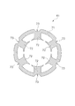
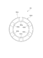
- FIG. 2 is a cross-sectional view of the stator taken along line II-II in FIG. It is a top view of the stator of a drive motor.
- FIG. 1 is a cross-sectional view of the stator taken along line II-II in FIG. It is a top view of the stator of a drive motor.
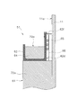
- FIG. 4 is a sectional view taken along line IV-IV in FIG. 3. It is a top view of an insulator. It is an enlarged view of the insulator shown by FIG. It is
- FIG. 10 is a cross-sectional view of the vicinity of an insulator according to Modification B.
- FIG. 10 is a cross-sectional view of the vicinity of an insulator according to Modification C.
- FIG. 10 is a cross-sectional view of the vicinity of an insulator according to Modification D.
- the compressor according to the present embodiment is a rotary compressor.
- the rotary compressor is a compressor that compresses the refrigerant circulating in the refrigerant circuit by rotating the piston eccentrically inside the cylinder and changing the volume of the space inside the cylinder.
- FIG. 1 is a longitudinal sectional view of a rotary compressor 101 according to this embodiment.
- the rotary compressor 101 mainly includes a casing 10, a compression mechanism 15, a drive motor 16, a crankshaft 17, a suction pipe 19, and a discharge pipe 20.
- a casing 10 mainly includes a casing 10, a compression mechanism 15, a drive motor 16, a crankshaft 17, a suction pipe 19, and a discharge pipe 20.
- each component of the rotary compressor 101 will be described.
- the casing 10 includes a substantially cylindrical trunk casing portion 11, a bowl-shaped upper wall portion 12 that is airtightly welded to the upper end portion of the trunk casing portion 11, and the trunk casing portion 11. And a bowl-shaped bottom wall portion 13 which is welded in an airtight manner to the lower end portion of the base plate.
- the casing 10 is formed of a rigid member that is unlikely to be deformed or damaged when pressure or temperature changes inside or outside the casing 10.
- the casing 10 is installed so that the substantially cylindrical axial direction of the body casing portion 11 is along the vertical direction.
- An oil storage part 10 a for storing lubricating oil is provided at the bottom of the casing 10.
- the lubricating oil is a refrigerating machine oil that is used to lubricate the sliding portion inside the rotary compressor 101.
- Casing 10 mainly accommodates compression mechanism 15, drive motor 16 disposed above compression mechanism 15, and crankshaft 17 disposed along the vertical direction.
- the compression mechanism 15 and the drive motor 16 are connected via a crankshaft 17.
- the suction pipe 19 and the discharge pipe 20 are joined to the casing 10 in an airtight manner.
- the compression mechanism 15 mainly includes a front head 23, a cylinder 24, a rear head 25, and a piston 21.
- the front head 23, the cylinder 24, and the rear head 25 are integrally fastened by laser welding.
- the space above the compression mechanism 15 is a high-pressure space S1 from which the refrigerant compressed by the compression mechanism 15 is discharged.
- the compression mechanism 15 has a compression chamber 40 that is a space surrounded by the front head 23, the cylinder 24, and the rear head 25.
- the compression chamber 40 is partitioned by the piston 21 into a suction chamber that communicates with the suction pipe 19 and a discharge chamber that communicates with the high-pressure space S1.
- the piston 21 is fitted to the eccentric shaft portion 17a of the crankshaft 17. Due to the rotation of the crankshaft 17, the piston 21 performs a revolving motion around the rotation shaft of the crankshaft 17 in the compression chamber 40. Due to the revolving motion of the piston 21, the volumes of the suction chamber and the discharge chamber of the compression chamber 40 change.
- the drive motor 16 is a brushless DC motor housed in the casing 10 and installed above the compression mechanism 15.
- the drive motor 16 mainly includes a stator 51 that is fixed to the inner peripheral surface of the casing 10 and a rotor 52 that is rotatably accommodated by providing an air gap inside the stator 51.
- the drive motor 16 is a three-phase motor having six concentrated winding coils, and is a variable speed motor driven by inverter control. Details of the configuration of the drive motor 16 will be described later.
- crankshaft 17 is arranged so that its central axis is along the vertical direction.
- the crankshaft 17 has an eccentric shaft portion 17a.
- the eccentric shaft portion 17 a of the crankshaft 17 is connected to the piston 21 of the compression mechanism 15.
- the end of the crankshaft 17 on the upper side in the vertical direction is connected to the rotor 52 of the drive motor 16.
- the crankshaft 17 is rotatably supported by the front head 23 and the rear head 25.
- the suction pipe 19 is a pipe that penetrates the body casing portion 11 of the casing 10. An end portion of the suction pipe 19 inside the casing 10 is fitted into the compression mechanism 15. The end of the suction pipe 19 outside the casing 10 is connected to the refrigerant circuit.
- the suction pipe 19 is a pipe for supplying a refrigerant from the refrigerant circuit to the compression mechanism 15.
- the discharge pipe 20 is a pipe that penetrates the upper wall portion 12 of the casing 10.
- the end of the discharge pipe 20 inside the casing 10 is located above the drive motor 16 in the high-pressure space S1.
- the end of the discharge pipe 20 outside the casing 10 is connected to the refrigerant circuit.
- the discharge pipe 20 is a pipe for supplying the refrigerant compressed by the compression mechanism 15 to the refrigerant circuit.
- FIG. 2 is a cross-sectional view of the stator 51 taken along line II-II in FIG.
- FIG. 3 is a top view of the stator 51 of the drive motor 16.
- 4 is a cross-sectional view taken along line IV-IV in FIG.
- the stator 51 includes a stator core 61 and a pair of insulators 62 and 63 attached to both end surfaces of the stator core 61 in the vertical direction.
- the insulator 62 is attached to the upper end surface of the stator core 61, and the insulator 63 is attached to the lower end surface of the stator core 61.
- stator core 61 is fixed to the casing 10. Specifically, the outer peripheral surface of the stator core 61 is welded to the inner peripheral surface of the casing 10. Three welding locations are provided at each of both ends of the stator core 61 in the vertical direction. The welding location may be appropriately determined depending on the weight of the stator core 61, the natural frequency, and the like.
- the stator core 61 may be fixed to the casing 10 by press fitting and shrink fitting.
- the stator core 61 has a cylindrical portion 71 and six teeth 72, as shown in FIG.
- Each tooth 72 protrudes from the inner peripheral surface of the cylindrical portion 71 toward the radially inner side of the cylindrical portion 71.
- the radial direction of the cylindrical portion 71 is in a horizontal plane orthogonal to the vertical direction.
- the six teeth 72 are arranged at equal intervals along the circumferential direction of the cylindrical portion 71.
- the six teeth 72 are arranged at positions that are six-fold symmetric with respect to the central axis of the cylindrical portion 71.
- each core cut 73 is a groove that is formed along the central axis of the cylindrical portion 71 from the upper end surface to the lower end surface of the cylindrical portion 71.
- Each core cut 73 is located on the radially outer side of the cylindrical portion 71 when viewed from the tooth 72.
- the six core cuts 73 are arranged at equal intervals along the circumferential direction of the cylindrical portion 71.
- the six core cuts 73 are arranged at positions that are six-fold symmetric with respect to the central axis of the cylindrical portion 71.
- the teeth 72 of the stator core 61 are wound with a conductor along with the insulator 62.
- a coil 72 a is formed on each tooth 72 of the stator core 61.
- the conductive wire wound around the teeth 72 and the insulator 62 is referred to as a winding 64.
- the winding 64 is individually wound around each tooth 72. That is, the coil 72a is a concentrated winding coil.
- the windings 64 of the teeth 72 are connected to each other via a jumper 65.
- An inter-coil space S2 is formed between the two adjacent coils 72a.
- the conducting wire corresponded to the neutral point of the coil 72a is accommodated in the insulation cap, and is inserted in the space S2 between coils which is the space between two adjacent coils 72a.
- FIG. 5 is a top view of the insulator 62 attached to the upper end surface of the stator core 61.
- the insulator 62 is an insulator attached to both end surfaces of the stator core 61 in the vertical direction.
- the insulator 62 is molded from a resin having high heat resistance such as liquid crystal polymer (LCP), polybutylene terephthalate (PBT), polyphenylene sulfide (PPS), polyimide, and polyester.
- LCP liquid crystal polymer
- PBT polybutylene terephthalate
- PPS polyphenylene sulfide
- polyester polyester
- the insulator 62 has an annular portion 62a and six projecting portions 62b.
- the annular portion 62 a contacts the upper end surface of the cylindrical portion 71 of the stator core 61.
- the protruding part 62b protrudes from the inner peripheral surface of the annular part 62a toward the radially inner side of the annular part 62a.
- Each protrusion 62 b comes into contact with the upper end surface of the tooth 72 of the stator core 61.
- the insulator 62 insulates the stator core 61 from the winding 64 of the coil 72a.
- the above description can also be applied to the insulator 63 attached to the lower end surface of the stator core 61.
- FIG. 6 is an enlarged view of the insulator 62 shown in FIG. FIG. 6 also shows the body casing portion 11 of the casing 10.
- the outer peripheral surface 62 d of the insulator 62 is in contact with the connecting wire 65.
- An insulating sheet 66 is installed between the outer peripheral surface 62 d of the insulator 62 and the inner peripheral surface 11 a of the body casing portion 11.
- the connecting wire 65 is located between the outer peripheral surface 62 d of the insulator 62 and the insulating sheet 66. That is, the insulating sheet 66 is installed between the crossover wire 65 and the casing 10, and prevents the crossover wire 65 and the casing 10 from being electrically connected.
- the crossover 65 and the insulating sheet 66 are shown as hatched areas.
- FIG. 7 is an external view of the insulating sheet 66.
- the insulating sheet 66 has a cylindrical shape.
- the material of the insulating sheet 66 is an insulator such as resin.
- the insulating sheet 66 is formed by rolling a rectangular resin film into a cylindrical shape.
- the thickness of the resin film is, for example, 0.1 mm to 1.0 mm.
- the cylindrical diameter of the insulating sheet 66 is set between the diameter of the outer peripheral surface 62 d of the insulator 62 and the diameter of the inner peripheral surface 11 a of the trunk casing portion 11.
- the insulating sheet 66 is installed between the insulator 62 attached to the upper end surface of the stator core 61 and the casing 10, but when the connecting wire 65 is installed below the stator core 61, It may be installed between the insulator 63 attached to the lower end face and the casing 10.
- the rotor 52 is connected to the crankshaft 17 passing through the rotation center in the vertical direction.
- the rotor 52 is connected to the compression mechanism 15 via the crankshaft 17.
- the rotor 52 includes a rotor core 52 a composed of a plurality of metal plates stacked in the vertical direction, and a plurality of magnets 52 b embedded in the rotor core 52 a.
- the magnets 52b are arranged at equal intervals along the circumferential direction of the rotor core 52a.
- the compressed high-pressure gas refrigerant is discharged from the discharge chamber to the high-pressure space S1.
- the discharged compressed refrigerant passes through an air gap that is a space between the stator 51 and the rotor 52 upward in the vertical direction. Thereafter, the compressed refrigerant is discharged from the discharge pipe 20 to the outside of the casing 10.
- the refrigerant compressed by the rotary compressor 101 is, for example, R410A, R22, R32, and carbon dioxide.
- the lubricating oil stored in the oil storage part 10a at the bottom of the casing 10 is supplied to the sliding part such as the compression mechanism 15.
- the lubricating oil supplied to the sliding portion of the compression mechanism 15 flows into the compression chamber 40.
- the lubricating oil becomes minute oil droplets and is mixed into the refrigerant gas. Therefore, the compressed refrigerant discharged from the compression mechanism 15 includes lubricating oil.
- Part of the lubricating oil contained in the compressed refrigerant is separated from the refrigerant by the centrifugal force caused by the refrigerant flow in the high-pressure space S ⁇ b> 1 above the drive motor 16, and adheres to the inner peripheral surface of the casing 10.
- the lubricating oil adhering to the inner peripheral surface of the casing 10 falls along the inner peripheral surface of the casing 10 and reaches the height position of the upper surface of the stator 51 of the drive motor 16. Then, the lubricating oil falls through the core cut 73 of the stator core 61. The lubricating oil that has dropped the core cut 73 finally returns to the oil reservoir 10a.
- the rotary compressor 101 includes a drive motor 16 having concentrated winding coils.
- the windings 64 of the coils 72 a are connected to each other via a jumper 65.
- the connecting wire 65 is installed so as to be wound around the insulator 62 while being in contact with the outer peripheral surface 62 d of the insulator 62 positioned above the stator 51.
- An insulating sheet 66 is installed between the body casing portion 11 of the casing 10 and the crossover 65.
- the cylindrical insulating sheet 66 is inserted and installed between the outer peripheral surface 62 d of the insulator 62 and the inner peripheral surface 11 a of the trunk casing portion 11.
- the insulating sheet 66 is an insulating member that prevents the connecting wire 65 and the casing 10 from being electrically connected.
- the connecting wire 65 and the casing 10 are appropriately insulated from each other. Therefore, the distance between the connecting wire 65 and the casing 10 should not be more than the distance specified by law. Don't be. In this case, it is difficult to make the back yoke, which is an annular portion outside the stator 51, thin.
- the distance between the crossover wire 65 and the casing 10 can be shortened by installing the insulating sheet 66 between the crossover wire 65 and the casing 10.
- the back yoke of the stator 51 can be made thin, and the drive motor 16 can be reduced in size. That is, by using the insulating sheet 66, the rotary compressor 101 can be reduced in size.
- the insulating sheet 66 is formed from a thin insulating member, and even if the temperature of the insulating sheet 66 rises during operation of the rotary compressor 101, the amount of heat that the insulating sheet 66 has is not large. Therefore, the insulating sheet 66 hardly affects the operation of the drive motor 16. Therefore, the rotary compressor 101 can achieve a reduction in size without reducing the efficiency of the drive motor 16.
- the insulating sheet 66 has a cylindrical shape having only side surfaces as shown in FIG. Therefore, the insulating sheet 66 is inserted into the gap between the outer peripheral surface 62d of the insulator 62 and the inner peripheral surface 11a of the trunk casing portion 11 from above the insulator 62, so that the connecting wire 65 and the casing 10 An insulating sheet 66 can be installed between them. Therefore, since the insulating sheet 66 can be easily installed, the rotary compressor 101 can easily achieve downsizing.
- the insulating sheet 66 is preferably molded from a heat-shrinkable material. That is, the insulating sheet 66 is preferably formed of an insulator having a property of contracting by heating. In this case, the insulating sheet 66 can be fixed to the insulator 62 by installing the cylindrical insulating sheet 66 between the crossover 65 and the casing 10 and then heating and contracting the insulating sheet 66. Therefore, the insulating sheet 66 can be easily fixed to the drive motor 16 by using the insulating sheet 66 that thermally contracts.
- the insulating sheet 66 has a cylindrical shape having only side surfaces as shown in FIG.
- FIG. 8 is an external view of the insulating sheet 66 in this modification.
- the insulating sheet 66 may have a cylindrical shape and may have a tab 66 a protruding from the lower end of the cylindrical shape.
- the tab 66 a of the insulating sheet 66 is a portion sandwiched between the stator 51 and the insulator 62.
- FIG. 9 is a diagram corresponding to FIG. 6 in the present modification.
- FIG. 9 shows an insulating sheet 66 having a tab 66 a sandwiched between the upper end surface of the stator 51 and the bottom surface of the insulator 62.
- the insulating sheet 66 is installed between the crossover 65 and the casing 10 with the tab 66a of the insulating sheet 66 being inserted between the stator 51 and the insulator 62. Since the tab 66 a of the insulating sheet 66 is sandwiched between the stator 51 and the insulator 62, the insulating sheet 66 is prevented from being detached from the stator 51. Therefore, in the present modification, the insulating sheet 66 can be easily fixed to the drive motor 16 by providing the insulating sheet 66 with the tab 66a.
- the insulating sheet 66 has a cylindrical shape having only side surfaces as shown in FIG.
- FIG. 10 is an external view of the insulating sheet 66 in this modification.
- the insulating sheet 66 may have an annular portion 66 b that is sandwiched between the stator 51 and the insulator 62 over the entire circumference of the stator 51.
- FIG. 10 is a development view of the insulating sheet 66 before being attached to the stator 51.
- the insulating sheet 66 has an annular portion 66b and a plurality of projecting portions 66c projecting outward from the annular portion 66b. As shown in FIG.
- the protrusion 66c may be formed by making a notch 66d along the radial direction of the annular portion 66b in a region outside the annular portion 66b.
- the cuts 66d are provided at equal intervals along the circumferential direction of the annular portion 66b.
- FIG. 11 is a diagram corresponding to FIG. 6 in the present modification. In FIG. 11, an insulating sheet 66 having an annular portion 66 b sandwiched between the upper end surface of the stator 51 and the bottom surface of the insulator 62 is shown.
- the insulating sheet 66 is inserted between the stator 51 and the insulator 62 and the insulating wire 66 is insulated between the crossover 65 and the casing 10.
- a protrusion 66c of the sheet 66 is installed.
- the protrusion 66 c of the insulating sheet 66 is located between the crossover wire 65 and the casing 10.
- the protruding part 66c stands upright with respect to the annular part 66b. Since the annular portion 66 b of the insulating sheet 66 is sandwiched between the stator 51 and the insulator 62, the insulating sheet 66 is prevented from being detached from the stator 51. Therefore, in this modification, the insulating sheet 66 can be easily fixed to the drive motor 16 by providing the insulating sheet 66 with the annular portion 66b and the protruding portion 66c.
- the notch 66d may not be formed in the insulating sheet 66.
- the insulating sheet 66 is attached to the drive motor 16 so that the annular portion 66b is sandwiched between the stator 51 and the insulator 62, and the protruding portion 66c is installed between the crossover 65 and the casing 10. Can be fixed to.
- the insulating sheet 66 is installed between the insulator 62 and the body casing portion 11 of the casing 10.
- FIG. 12 is a diagram corresponding to FIG. 6 in this modification.
- the insulator 62 may have a protrusion 62 e that protrudes toward the inner peripheral surface 11 a of the body casing portion 11.
- the insulating sheet 66 is disposed between the insulator 62 and the trunk casing portion 11 and between the stator 51 and the protrusion 62e.
- the insulating sheet 66 is installed between the insulator 62 and the trunk casing 11. As shown in FIG. 12, the insulating sheet 66 is installed below the protrusion 62 e of the insulator 62 and above the upper end surface of the stator 51. The protrusion 62e of the insulator 62 prevents the insulating sheet 66 from coming off from the gap between the insulator 62 and the body casing portion 11. Therefore, this modification can effectively suppress the insulating sheet 66 from being detached from the drive motor 16.
- FIG. 13 is a diagram corresponding to FIG. 6 in the present modification.
- a sheet fixing member 62 f may be installed between the insulator 62 and the body casing portion 11.
- the sheet fixing member 62f is a member independent of the insulator 62.
- the sheet fixing member 62f may be a member that can be attached to the insulator 62.
- the insulating sheet 66 is disposed between the insulator 62 and the body casing portion 11 and between the stator 51 and the sheet fixing member 62f.
- the insulating sheet 66 is installed between the insulator 62 and the trunk casing 11. As shown in FIG. 13, the insulating sheet 66 is installed below the sheet fixing member 62 f and above the upper end surface of the stator 51.
- the sheet fixing member 62 f prevents the insulating sheet 66 from coming off from the gap between the insulator 62 and the body casing portion 11. Therefore, this modification can effectively suppress the insulating sheet 66 from being detached from the drive motor 16.
- the insulating sheet 66 is composed of a single sheet, but may be composed of a plurality of sheets.
- a plurality of film-like insulating members constituting the insulating sheet 66 are inserted into the gap between the jumper wire 65 and the casing 10 from above the insulator 62, and the jumper wire 65 is connected to the casing 10 in the entire gap.
- An insulating sheet 66 may be installed so as to be insulated from the surface.
- the rotary compressor 101 is used as the compressor including the drive motor 16 in which the insulating sheet 66 is installed between the crossover 65 and the casing 10.
- a scroll compressor and a reciprocating compressor are used.
- a type compressor may be used.
- the drive motor 16 has a concentrated winding coil, but may have a distributed winding coil in which the winding of the coil is wound over a plurality of teeth 72.
- the compressor according to the present invention can achieve downsizing while maintaining the efficiency of the motor.
Landscapes
- Engineering & Computer Science (AREA)
- Power Engineering (AREA)
- Mechanical Engineering (AREA)
- General Engineering & Computer Science (AREA)
- Insulation, Fastening Of Motor, Generator Windings (AREA)
- Compressor (AREA)
- Applications Or Details Of Rotary Compressors (AREA)
Abstract
Description
図1は、本実施形態に係るロータリ圧縮機101の縦断面図である。ロータリ圧縮機101は、主として、ケーシング10と、圧縮機構15と、駆動モータ16と、クランク軸17と、吸入管19と、吐出管20とを備える。以下、ロータリ圧縮機101の各構成要素について説明する。
ケーシング10は、略円筒状の胴部ケーシング部11と、胴部ケーシング部11の上端部に気密状に溶接される椀状の上壁部12と、胴部ケーシング部11の下端部に気密状に溶接される椀状の底壁部13とを有する。ケーシング10は、ケーシング10の内部および外部において圧力や温度が変化した場合に、変形および破損が起こりにくい剛性部材で成型されている。ケーシング10は、胴部ケーシング部11の略円筒状の軸方向が鉛直方向に沿うように設置されている。ケーシング10の底部には、潤滑油が貯留される油貯留部10aが設けられている。潤滑油は、ロータリ圧縮機101内部の摺動部を潤滑するために用いられる冷凍機油である。
圧縮機構15は、主として、フロントヘッド23と、シリンダ24と、リアヘッド25と、ピストン21とから構成されている。フロントヘッド23、シリンダ24およびリアヘッド25は、レーザ溶接によって一体的に締結されている。圧縮機構15の上方の空間は、圧縮機構15によって圧縮された冷媒が吐出される高圧空間S1である。
駆動モータ16は、ケーシング10の内部に収容され、圧縮機構15の上方に設置されるブラシレスDCモータである。駆動モータ16は、主として、ケーシング10の内周面に固定されるステータ51と、ステータ51の内側にエアギャップを設けて回転自在に収容されるロータ52とから構成される。駆動モータ16は、6個の集中巻コイルを有する三相モータであり、インバータ制御によって駆動される可変速モータである。駆動モータ16の構成の詳細については、後述する。
クランク軸17は、その中心軸が鉛直方向に沿うように配置されている。クランク軸17は、偏心軸部17aを有している。クランク軸17の偏心軸部17aは、圧縮機構15のピストン21と連結している。クランク軸17の鉛直方向上側の端部は、駆動モータ16のロータ52と連結している。クランク軸17は、フロントヘッド23およびリアヘッド25によって、回転自在に支持されている。
吸入管19は、ケーシング10の胴部ケーシング部11を貫通する管である。ケーシング10の内部にある吸入管19の端部は、圧縮機構15に嵌め込まれている。ケーシング10の外部にある吸入管19の端部は、冷媒回路に接続されている。吸入管19は、冷媒回路から圧縮機構15に冷媒を供給するための管である。
吐出管20は、ケーシング10の上壁部12を貫通する管である。ケーシング10の内部にある吐出管20の端部は、高圧空間S1において駆動モータ16の上方に位置している。ケーシング10の外部にある吐出管20の端部は、冷媒回路に接続されている。吐出管20は、圧縮機構15によって圧縮された冷媒を冷媒回路に供給するための管である。
駆動モータ16の構成の詳細について説明する。図2は、図1の線分II-IIにおけるステータ51の断面図である。図3は、駆動モータ16のステータ51の上面図である。図4は、図3の線分IV-IVにおける断面図である。
ステータ51は、図4に示されるように、ステータコア61と、ステータコア61の鉛直方向の両端面に取り付けられる一対のインシュレータ62,63とを有する。インシュレータ62は、ステータコア61の上側の端面に取り付けられ、インシュレータ63は、ステータコア61の下側の端面に取り付けられる。
ステータコア61は、ケーシング10に固定されている。具体的には、ステータコア61の外周面は、ケーシング10の内周面に溶接されている。溶接箇所は、ステータコア61の鉛直方向の両端部のそれぞれに3ケ所ずつ設けられている。溶接箇所は、ステータコア61の重量および固有振動数等により、適宜に決定されてもよい。ステータコア61は、圧入および焼嵌めによって、ケーシング10に固定されてもよい。
図5は、ステータコア61の上側の端面に取り付けられるインシュレータ62の上面図である。インシュレータ62は、ステータコア61の鉛直方向の両端面に取り付けられる絶縁体である。インシュレータ62は、例えば、液晶ポリマー(LCP)、ポリブチレンテレフタレート(PBT)、ポリフェニレンサルファイド(PPS)、ポリイミドおよびポリエステル等の高い耐熱性を有する樹脂から成型される。
ロータ52は、その回転中心を鉛直方向に貫通するクランク軸17に連結されている。ロータ52は、クランク軸17を介して、圧縮機構15と接続されている。ロータ52は、図1に示されるように、鉛直方向に積層された複数の金属板から構成されるロータコア52aと、ロータコア52aに埋め込まれている複数の磁石52bとを有する。磁石52bは、ロータコア52aの周方向に沿って、等間隔に配置されている。
駆動モータ16が駆動すると、ロータ52が回転して、クランク軸17が軸回転する。クランク軸17の軸回転により、圧縮機構15のピストン21は、圧縮室40において、クランク軸17の回転軸を中心とする公転運動を行う。ピストン21の公転運動によって、圧縮室40の吸入室および吐出室の容積が変化する。これにより、低圧のガス冷媒は、吸入管19から圧縮室40の吸入室に吸入される。吸入室の容積は、ピストン21の公転運動によって減少し、その結果、冷媒は圧縮され、吸入室は吐出室となる。圧縮された高圧のガス冷媒は、吐出室から高圧空間S1に吐出される。吐出された圧縮冷媒は、鉛直方向上方に向かって、ステータ51とロータ52との間の空間であるエアギャップを通過する。その後、圧縮冷媒は、吐出管20からケーシング10の外部に吐出される。ロータリ圧縮機101で圧縮される冷媒は、例えば、R410A、R22、R32および二酸化炭素である。
ロータリ圧縮機101は、集中巻コイルを有する駆動モータ16を備えている。各コイル72aの巻線64は、渡り線65を介して互いに接続されている。渡り線65は、ステータ51の上方に位置するインシュレータ62の外周面62dに接しながら、インシュレータ62に巻かれるように設置されている。
(5-1)変形例A
本実施形態では、絶縁シート66は、図7に示されるように、側面のみを有する円筒形状を有している。図8は、本変形例における絶縁シート66の外観図である。図8に示されるように、絶縁シート66は、円筒形状を有し、かつ、円筒形状の下端から突出しているタブ66aを有してもよい。絶縁シート66のタブ66aは、ステータ51とインシュレータ62との間に挟まれる部分である。図9は、本変形例における、図6に相当する図である。図9には、ステータ51の上端面と、インシュレータ62の底面との間に挟まれているタブ66aを有する絶縁シート66が示されている。
本実施形態では、絶縁シート66は、図7に示されるように、側面のみを有する円筒形状を有している。図10は、本変形例における絶縁シート66の外観図である。図10に示されるように、絶縁シート66は、ステータ51の全周に亘って、ステータ51とインシュレータ62との間に挟まれる環状部66bを有してもよい。図10は、ステータ51に取り付ける前の絶縁シート66の展開図である。絶縁シート66は、環状部66bと、環状部66bから外側に向かって突出している複数の突出部66cとを有している。図10に示されるように、突出部66cは、環状部66bの外側の領域に、環状部66bの径方向に沿って切り込み66dを入れることで形成されてもよい。切り込み66dは、環状部66bの周方向に沿って等間隔に設けられている。図11は、本変形例における、図6に相当する図である。図11には、ステータ51の上端面と、インシュレータ62の底面との間に挟まれている環状部66bを有する絶縁シート66が示されている。
本実施形態では、絶縁シート66は、インシュレータ62と、ケーシング10の胴部ケーシング部11との間に設置されている。図12は、本変形例における、図6に相当する図である。図12に示されるように、インシュレータ62は、胴部ケーシング部11の内周面11aに向かって突き出ている突起部62eを有してもよい。絶縁シート66は、インシュレータ62と胴部ケーシング部11との間であって、ステータ51と突起部62eとの間に設置されている。
本実施形態では、絶縁シート66は、インシュレータ62と、ケーシング10の胴部ケーシング部11との間に設置されている。図13は、本変形例における、図6に相当する図である。図13に示されるように、インシュレータ62と胴部ケーシング部11との間に、シート固定部材62fが設置されてもよい。シート固定部材62fは、インシュレータ62から独立した部材である。シート固定部材62fは、インシュレータ62に取り付け可能な部材であってもよい。絶縁シート66は、インシュレータ62と胴部ケーシング部11との間であって、ステータ51とシート固定部材62fとの間に設置されている。
本実施形態では、絶縁シート66は、一枚のシートから構成されているが、複数のシートから構成されてもよい。例えば、絶縁シート66を構成する複数のフィルム状の絶縁部材を、インシュレータ62の上方から、渡り線65とケーシング10との間の隙間に挿入して、その隙間の全体において渡り線65がケーシング10から絶縁されるように、絶縁シート66を設置してもよい。
本実施形態では、渡り線65とケーシング10との間に絶縁シート66が設置されている駆動モータ16を備える圧縮機として、ロータリ圧縮機101が用いられているが、例えば、スクロール圧縮機およびレシプロ式圧縮機が用いられてもよい。
15 圧縮機構
16 駆動モータ(モータ)
51 ステータ
62 インシュレータ
62e 突起部
62f シート固定部材
64 巻線
65 渡り線
66 絶縁シート
66a タブ
66b 環状部
72 ティース
101 ロータリ圧縮機(圧縮機)
Claims (7)
- ケーシング(10)と、
前記ケーシングの内部に設置される圧縮機構(15)と、
前記ケーシングの内部に設置され、前記圧縮機構を駆動するモータ(16)と、
を備え、
前記モータは、複数のティース(72)を有するステータ(51)と、前記ステータに隣接するインシュレータ(62)とを有し、前記インシュレータを介して前記ティースに巻線(64)が巻かれた集中巻モータであり、
前記巻線の渡り線(65)と前記ケーシングとの間に、絶縁シート(66)が設置されている、
圧縮機(101)。 - 前記絶縁シートは、前記インシュレータと前記ケーシングとの間に設置され、円筒形状を有する、
請求項1に記載の圧縮機。 - 前記絶縁シートは、前記ステータと前記インシュレータとの間に挟まれるタブ(66a)を有する、
請求項2に記載の圧縮機。 - 前記絶縁シートは、熱収縮する材質で成形されている、
請求項2または3に記載の圧縮機。 - 前記絶縁シートは、前記インシュレータと前記ケーシングとの間に設置され、
前記絶縁シートは、前記ステータの全周に亘って、前記ステータと前記インシュレータとの間に挟まれる環状部(66b)を有する、
請求項1に記載の圧縮機。 - 前記インシュレータは、前記ケーシングに向かって突き出ている突起部(62e)を有し、
前記絶縁シートは、前記インシュレータと前記ケーシングとの間であって、前記ステータと前記突起部との間に設置されている、
請求項1から5のいずれか1項に記載の圧縮機。 - 前記インシュレータと前記ケーシングとの間に設置されるシート固定部材(62f)をさらに備え、
前記絶縁シートは、前記インシュレータと前記ケーシングとの間であって、前記ステータと前記シート固定部材との間に設置されている、
請求項1から5のいずれか1項に記載の圧縮機。
Priority Applications (6)
| Application Number | Priority Date | Filing Date | Title |
|---|---|---|---|
| ES14868338.6T ES2672008T3 (es) | 2013-12-02 | 2014-12-02 | Compresor |
| MX2016006881A MX351459B (es) | 2013-12-02 | 2014-12-02 | Compresor. |
| CN201480065368.4A CN105993114B (zh) | 2013-12-02 | 2014-12-02 | 压缩机 |
| US15/100,576 US9608490B2 (en) | 2013-12-02 | 2014-12-02 | Compressor |
| EP14868338.6A EP3079236B1 (en) | 2013-12-02 | 2014-12-02 | Compressor |
| BR112016012145-7A BR112016012145B1 (pt) | 2013-12-02 | 2014-12-02 | Compressor |
Applications Claiming Priority (2)
| Application Number | Priority Date | Filing Date | Title |
|---|---|---|---|
| JP2013-249160 | 2013-12-02 | ||
| JP2013249160A JP5831533B2 (ja) | 2013-12-02 | 2013-12-02 | 圧縮機 |
Publications (1)
| Publication Number | Publication Date |
|---|---|
| WO2015083687A1 true WO2015083687A1 (ja) | 2015-06-11 |
Family
ID=53273449
Family Applications (1)
| Application Number | Title | Priority Date | Filing Date |
|---|---|---|---|
| PCT/JP2014/081838 Ceased WO2015083687A1 (ja) | 2013-12-02 | 2014-12-02 | 圧縮機 |
Country Status (9)
| Country | Link |
|---|---|
| US (1) | US9608490B2 (ja) |
| EP (1) | EP3079236B1 (ja) |
| JP (1) | JP5831533B2 (ja) |
| CN (1) | CN105993114B (ja) |
| BR (1) | BR112016012145B1 (ja) |
| ES (1) | ES2672008T3 (ja) |
| MX (1) | MX351459B (ja) |
| MY (1) | MY164325A (ja) |
| WO (1) | WO2015083687A1 (ja) |
Cited By (1)
| Publication number | Priority date | Publication date | Assignee | Title |
|---|---|---|---|---|
| CN107528401A (zh) * | 2016-06-20 | 2017-12-29 | 马渊马达株式会社 | 定子及马达 |
Families Citing this family (6)
| Publication number | Priority date | Publication date | Assignee | Title |
|---|---|---|---|---|
| JP5831533B2 (ja) | 2013-12-02 | 2015-12-09 | ダイキン工業株式会社 | 圧縮機 |
| JP2015226330A (ja) * | 2014-05-26 | 2015-12-14 | 日立アプライアンス株式会社 | ポンプ駆動用モータとそれを用いたポンプ装置 |
| JP2020188640A (ja) * | 2019-05-17 | 2020-11-19 | パナソニックIpマネジメント株式会社 | 冷凍サイクル装置 |
| JP6844676B1 (ja) * | 2019-11-29 | 2021-03-17 | ダイキン工業株式会社 | スクロール圧縮機 |
| CN112701832B (zh) * | 2020-11-12 | 2022-07-19 | 奇瑞新能源汽车股份有限公司 | 定子绝缘罩、电机定子及电机 |
| CN114795658B (zh) * | 2022-03-11 | 2023-05-16 | 河北医科大学第二医院 | 一种带有负压装置的vsd贴 |
Citations (5)
| Publication number | Priority date | Publication date | Assignee | Title |
|---|---|---|---|---|
| JPH05146106A (ja) | 1991-11-18 | 1993-06-11 | Matsushita Seiko Co Ltd | 樹脂モールドモータの固定子 |
| JPH11178264A (ja) * | 1997-12-10 | 1999-07-02 | Fuji Electric Co Ltd | 低圧電気機械用の電機子巻線 |
| JP2002044892A (ja) | 2000-07-27 | 2002-02-08 | Matsushita Electric Ind Co Ltd | 電動機およびそれを搭載した電動圧縮機 |
| JP2009077477A (ja) * | 2007-09-19 | 2009-04-09 | Komatsu Ltd | 電動モータ |
| JP2009240119A (ja) * | 2008-03-28 | 2009-10-15 | Daikin Ind Ltd | ステータ、モータおよび圧縮機 |
Family Cites Families (8)
| Publication number | Priority date | Publication date | Assignee | Title |
|---|---|---|---|---|
| DE19902837C1 (de) * | 1999-01-20 | 2000-08-10 | Siemens Ag | Rotierende elektrische Maschine mit permanenterregtem Rotor |
| US6445095B1 (en) * | 2001-01-11 | 2002-09-03 | Ford Global Technologies, Inc. | Electric machine with laminated cooling rings |
| JP4270307B2 (ja) * | 2007-06-25 | 2009-05-27 | トヨタ自動車株式会社 | 渡り線モジュール |
| JP5273448B2 (ja) * | 2008-06-17 | 2013-08-28 | 日本電産株式会社 | モータ |
| CN201323475Y (zh) * | 2009-03-06 | 2009-10-07 | 黄石艾博科技发展有限公司 | 带外保护绝缘圈的定子 |
| JP2012196086A (ja) * | 2011-03-17 | 2012-10-11 | Daikin Ind Ltd | ステータ、モータ、圧縮機、および、ステータの組立方法 |
| JP5607708B2 (ja) * | 2012-12-04 | 2014-10-15 | ファナック株式会社 | 電動機の固定子 |
| JP5831533B2 (ja) | 2013-12-02 | 2015-12-09 | ダイキン工業株式会社 | 圧縮機 |
-
2013
- 2013-12-02 JP JP2013249160A patent/JP5831533B2/ja active Active
-
2014
- 2014-12-02 CN CN201480065368.4A patent/CN105993114B/zh active Active
- 2014-12-02 MX MX2016006881A patent/MX351459B/es active IP Right Grant
- 2014-12-02 EP EP14868338.6A patent/EP3079236B1/en active Active
- 2014-12-02 ES ES14868338.6T patent/ES2672008T3/es active Active
- 2014-12-02 US US15/100,576 patent/US9608490B2/en not_active Expired - Fee Related
- 2014-12-02 WO PCT/JP2014/081838 patent/WO2015083687A1/ja not_active Ceased
- 2014-12-02 BR BR112016012145-7A patent/BR112016012145B1/pt active IP Right Grant
- 2014-12-02 MY MYPI2016701937A patent/MY164325A/en unknown
Patent Citations (5)
| Publication number | Priority date | Publication date | Assignee | Title |
|---|---|---|---|---|
| JPH05146106A (ja) | 1991-11-18 | 1993-06-11 | Matsushita Seiko Co Ltd | 樹脂モールドモータの固定子 |
| JPH11178264A (ja) * | 1997-12-10 | 1999-07-02 | Fuji Electric Co Ltd | 低圧電気機械用の電機子巻線 |
| JP2002044892A (ja) | 2000-07-27 | 2002-02-08 | Matsushita Electric Ind Co Ltd | 電動機およびそれを搭載した電動圧縮機 |
| JP2009077477A (ja) * | 2007-09-19 | 2009-04-09 | Komatsu Ltd | 電動モータ |
| JP2009240119A (ja) * | 2008-03-28 | 2009-10-15 | Daikin Ind Ltd | ステータ、モータおよび圧縮機 |
Non-Patent Citations (1)
| Title |
|---|
| See also references of EP3079236A4 |
Cited By (1)
| Publication number | Priority date | Publication date | Assignee | Title |
|---|---|---|---|---|
| CN107528401A (zh) * | 2016-06-20 | 2017-12-29 | 马渊马达株式会社 | 定子及马达 |
Also Published As
| Publication number | Publication date |
|---|---|
| JP2015107019A (ja) | 2015-06-08 |
| MX351459B (es) | 2017-10-16 |
| EP3079236A4 (en) | 2017-02-01 |
| EP3079236B1 (en) | 2018-03-07 |
| BR112016012145A2 (pt) | 2017-08-08 |
| JP5831533B2 (ja) | 2015-12-09 |
| BR112016012145B1 (pt) | 2021-12-28 |
| MX2016006881A (es) | 2016-12-15 |
| CN105993114A (zh) | 2016-10-05 |
| ES2672008T3 (es) | 2018-06-12 |
| MY164325A (en) | 2017-12-15 |
| US20160315517A1 (en) | 2016-10-27 |
| US9608490B2 (en) | 2017-03-28 |
| CN105993114B (zh) | 2017-09-19 |
| EP3079236A1 (en) | 2016-10-12 |
Similar Documents
| Publication | Publication Date | Title |
|---|---|---|
| JP5831533B2 (ja) | 圧縮機 | |
| JP2008211873A (ja) | ステータ、モータおよび圧縮機 | |
| CN102301568A (zh) | 定子、电动机以及压缩机 | |
| JP2014031771A (ja) | 電動圧縮機 | |
| EP2040358A2 (en) | Interphase insulating sheet of rotating electric machine, method for manufacturing interphase insulating sheet, and electric compressor | |
| CN205725224U (zh) | 马达以及压缩机 | |
| JP2006183474A (ja) | 密閉型電動圧縮機および冷凍サイクル装置 | |
| WO2019039143A1 (ja) | 固定子、この固定子を備えるモータ、このモータを備える圧縮機、及びこの圧縮機を備える空気調和機 | |
| JP2018061420A (ja) | ステータ、その製造方法、そのステータを用いたモータ及び圧縮機 | |
| JP6094565B2 (ja) | ステータおよびモータ | |
| JP6395948B2 (ja) | 固定子鉄心、圧縮機及び冷凍サイクル装置 | |
| JP2016073137A (ja) | ステータおよびモータ | |
| JP2014050281A (ja) | ステータおよび圧縮機 | |
| CN111247719B (zh) | 定子、电动机和压缩机 | |
| JP2018011394A (ja) | インシュレータ、および、インシュレータの製造方法 | |
| JP5211713B2 (ja) | ステータ、モータおよび圧縮機 | |
| WO2022264318A1 (ja) | 圧縮機用電動機、圧縮機、冷凍サイクル装置及び圧縮機用電動機の製造方法 | |
| JP6362771B2 (ja) | 回転電動機及び圧縮機 | |
| JP6005296B2 (ja) | 電動機またはそれを用いた圧縮機 | |
| WO2025177674A1 (ja) | 電動機、電動機の製造方法、圧縮機、及び機器 | |
| WO2018163370A1 (ja) | 回転電機、圧縮機および冷凍サイクル装置 | |
| JP6531600B2 (ja) | 電動圧縮機 | |
| JP2021124016A (ja) | 圧縮機 | |
| JP6135632B2 (ja) | 圧縮機 | |
| WO2022113346A1 (ja) | ステータ、モータ、圧縮機および冷凍サイクル装置 |
Legal Events
| Date | Code | Title | Description |
|---|---|---|---|
| 121 | Ep: the epo has been informed by wipo that ep was designated in this application |
Ref document number: 14868338 Country of ref document: EP Kind code of ref document: A1 |
|
| WWE | Wipo information: entry into national phase |
Ref document number: MX/A/2016/006881 Country of ref document: MX |
|
| WWE | Wipo information: entry into national phase |
Ref document number: 15100576 Country of ref document: US |
|
| NENP | Non-entry into the national phase |
Ref country code: DE |
|
| REG | Reference to national code |
Ref country code: BR Ref legal event code: B01A Ref document number: 112016012145 Country of ref document: BR |
|
| REEP | Request for entry into the european phase |
Ref document number: 2014868338 Country of ref document: EP |
|
| WWE | Wipo information: entry into national phase |
Ref document number: 2014868338 Country of ref document: EP |
|
| WWE | Wipo information: entry into national phase |
Ref document number: IDP00201604386 Country of ref document: ID |
|
| ENP | Entry into the national phase |
Ref document number: 112016012145 Country of ref document: BR Kind code of ref document: A2 Effective date: 20160527 |