WO2015083699A1 - 車両 - Google Patents
車両 Download PDFInfo
- Publication number
- WO2015083699A1 WO2015083699A1 PCT/JP2014/081867 JP2014081867W WO2015083699A1 WO 2015083699 A1 WO2015083699 A1 WO 2015083699A1 JP 2014081867 W JP2014081867 W JP 2014081867W WO 2015083699 A1 WO2015083699 A1 WO 2015083699A1
- Authority
- WO
- WIPO (PCT)
- Prior art keywords
- vehicle
- mounted object
- extending
- drive device
- wheel drive
- Prior art date
- Legal status (The legal status is an assumption and is not a legal conclusion. Google has not performed a legal analysis and makes no representation as to the accuracy of the status listed.)
- Ceased
Links
Images


Classifications
-
- B—PERFORMING OPERATIONS; TRANSPORTING
- B60—VEHICLES IN GENERAL
- B60K—ARRANGEMENT OR MOUNTING OF PROPULSION UNITS OR OF TRANSMISSIONS IN VEHICLES; ARRANGEMENT OR MOUNTING OF PLURAL DIVERSE PRIME-MOVERS IN VEHICLES; AUXILIARY DRIVES FOR VEHICLES; INSTRUMENTATION OR DASHBOARDS FOR VEHICLES; ARRANGEMENTS IN CONNECTION WITH COOLING, AIR INTAKE, GAS EXHAUST OR FUEL SUPPLY OF PROPULSION UNITS IN VEHICLES
- B60K6/00—Arrangement or mounting of plural diverse prime-movers for mutual or common propulsion, e.g. hybrid propulsion systems comprising electric motors and internal combustion engines
- B60K6/20—Arrangement or mounting of plural diverse prime-movers for mutual or common propulsion, e.g. hybrid propulsion systems comprising electric motors and internal combustion engines the prime-movers consisting of electric motors and internal combustion engines, e.g. HEVs
- B60K6/22—Arrangement or mounting of plural diverse prime-movers for mutual or common propulsion, e.g. hybrid propulsion systems comprising electric motors and internal combustion engines the prime-movers consisting of electric motors and internal combustion engines, e.g. HEVs characterised by apparatus, components or means specially adapted for HEVs
- B60K6/26—Arrangement or mounting of plural diverse prime-movers for mutual or common propulsion, e.g. hybrid propulsion systems comprising electric motors and internal combustion engines the prime-movers consisting of electric motors and internal combustion engines, e.g. HEVs characterised by apparatus, components or means specially adapted for HEVs characterised by the motors or the generators
-
- B—PERFORMING OPERATIONS; TRANSPORTING
- B60—VEHICLES IN GENERAL
- B60K—ARRANGEMENT OR MOUNTING OF PROPULSION UNITS OR OF TRANSMISSIONS IN VEHICLES; ARRANGEMENT OR MOUNTING OF PLURAL DIVERSE PRIME-MOVERS IN VEHICLES; AUXILIARY DRIVES FOR VEHICLES; INSTRUMENTATION OR DASHBOARDS FOR VEHICLES; ARRANGEMENTS IN CONNECTION WITH COOLING, AIR INTAKE, GAS EXHAUST OR FUEL SUPPLY OF PROPULSION UNITS IN VEHICLES
- B60K1/00—Arrangement or mounting of electrical propulsion units
- B60K1/02—Arrangement or mounting of electrical propulsion units comprising more than one electric motor
-
- B—PERFORMING OPERATIONS; TRANSPORTING
- B60—VEHICLES IN GENERAL
- B60K—ARRANGEMENT OR MOUNTING OF PROPULSION UNITS OR OF TRANSMISSIONS IN VEHICLES; ARRANGEMENT OR MOUNTING OF PLURAL DIVERSE PRIME-MOVERS IN VEHICLES; AUXILIARY DRIVES FOR VEHICLES; INSTRUMENTATION OR DASHBOARDS FOR VEHICLES; ARRANGEMENTS IN CONNECTION WITH COOLING, AIR INTAKE, GAS EXHAUST OR FUEL SUPPLY OF PROPULSION UNITS IN VEHICLES
- B60K17/00—Arrangement or mounting of transmissions in vehicles
- B60K17/04—Arrangement or mounting of transmissions in vehicles characterised by arrangement, location or kind of gearing
- B60K17/043—Transmission unit disposed in on near the vehicle wheel, or between the differential gear unit and the wheel
- B60K17/046—Transmission unit disposed in on near the vehicle wheel, or between the differential gear unit and the wheel with planetary gearing having orbital motion
-
- B—PERFORMING OPERATIONS; TRANSPORTING
- B60—VEHICLES IN GENERAL
- B60K—ARRANGEMENT OR MOUNTING OF PROPULSION UNITS OR OF TRANSMISSIONS IN VEHICLES; ARRANGEMENT OR MOUNTING OF PLURAL DIVERSE PRIME-MOVERS IN VEHICLES; AUXILIARY DRIVES FOR VEHICLES; INSTRUMENTATION OR DASHBOARDS FOR VEHICLES; ARRANGEMENTS IN CONNECTION WITH COOLING, AIR INTAKE, GAS EXHAUST OR FUEL SUPPLY OF PROPULSION UNITS IN VEHICLES
- B60K6/00—Arrangement or mounting of plural diverse prime-movers for mutual or common propulsion, e.g. hybrid propulsion systems comprising electric motors and internal combustion engines
- B60K6/20—Arrangement or mounting of plural diverse prime-movers for mutual or common propulsion, e.g. hybrid propulsion systems comprising electric motors and internal combustion engines the prime-movers consisting of electric motors and internal combustion engines, e.g. HEVs
- B60K6/22—Arrangement or mounting of plural diverse prime-movers for mutual or common propulsion, e.g. hybrid propulsion systems comprising electric motors and internal combustion engines the prime-movers consisting of electric motors and internal combustion engines, e.g. HEVs characterised by apparatus, components or means specially adapted for HEVs
- B60K6/40—Arrangement or mounting of plural diverse prime-movers for mutual or common propulsion, e.g. hybrid propulsion systems comprising electric motors and internal combustion engines the prime-movers consisting of electric motors and internal combustion engines, e.g. HEVs characterised by apparatus, components or means specially adapted for HEVs characterised by the assembly or relative disposition of components
-
- B—PERFORMING OPERATIONS; TRANSPORTING
- B60—VEHICLES IN GENERAL
- B60K—ARRANGEMENT OR MOUNTING OF PROPULSION UNITS OR OF TRANSMISSIONS IN VEHICLES; ARRANGEMENT OR MOUNTING OF PLURAL DIVERSE PRIME-MOVERS IN VEHICLES; AUXILIARY DRIVES FOR VEHICLES; INSTRUMENTATION OR DASHBOARDS FOR VEHICLES; ARRANGEMENTS IN CONNECTION WITH COOLING, AIR INTAKE, GAS EXHAUST OR FUEL SUPPLY OF PROPULSION UNITS IN VEHICLES
- B60K6/00—Arrangement or mounting of plural diverse prime-movers for mutual or common propulsion, e.g. hybrid propulsion systems comprising electric motors and internal combustion engines
- B60K6/20—Arrangement or mounting of plural diverse prime-movers for mutual or common propulsion, e.g. hybrid propulsion systems comprising electric motors and internal combustion engines the prime-movers consisting of electric motors and internal combustion engines, e.g. HEVs
- B60K6/50—Architecture of the driveline characterised by arrangement or kind of transmission units
- B60K6/52—Driving a plurality of drive axles, e.g. four-wheel drive
-
- B—PERFORMING OPERATIONS; TRANSPORTING
- B60—VEHICLES IN GENERAL
- B60K—ARRANGEMENT OR MOUNTING OF PROPULSION UNITS OR OF TRANSMISSIONS IN VEHICLES; ARRANGEMENT OR MOUNTING OF PLURAL DIVERSE PRIME-MOVERS IN VEHICLES; AUXILIARY DRIVES FOR VEHICLES; INSTRUMENTATION OR DASHBOARDS FOR VEHICLES; ARRANGEMENTS IN CONNECTION WITH COOLING, AIR INTAKE, GAS EXHAUST OR FUEL SUPPLY OF PROPULSION UNITS IN VEHICLES
- B60K7/00—Disposition of motor in, or adjacent to, traction wheel
- B60K7/0007—Disposition of motor in, or adjacent to, traction wheel the motor being electric
-
- B—PERFORMING OPERATIONS; TRANSPORTING
- B62—LAND VEHICLES FOR TRAVELLING OTHERWISE THAN ON RAILS
- B62D—MOTOR VEHICLES; TRAILERS
- B62D21/00—Understructures, i.e. chassis frame on which a vehicle body may be mounted
- B62D21/15—Understructures, i.e. chassis frame on which a vehicle body may be mounted having impact absorbing means, e.g. a frame designed to permanently or temporarily change shape or dimension upon impact with another body
-
- B—PERFORMING OPERATIONS; TRANSPORTING
- B60—VEHICLES IN GENERAL
- B60K—ARRANGEMENT OR MOUNTING OF PROPULSION UNITS OR OF TRANSMISSIONS IN VEHICLES; ARRANGEMENT OR MOUNTING OF PLURAL DIVERSE PRIME-MOVERS IN VEHICLES; AUXILIARY DRIVES FOR VEHICLES; INSTRUMENTATION OR DASHBOARDS FOR VEHICLES; ARRANGEMENTS IN CONNECTION WITH COOLING, AIR INTAKE, GAS EXHAUST OR FUEL SUPPLY OF PROPULSION UNITS IN VEHICLES
- B60K1/00—Arrangement or mounting of electrical propulsion units
- B60K2001/001—Arrangement or mounting of electrical propulsion units one motor mounted on a propulsion axle for rotating right and left wheels of this axle
-
- B—PERFORMING OPERATIONS; TRANSPORTING
- B60—VEHICLES IN GENERAL
- B60K—ARRANGEMENT OR MOUNTING OF PROPULSION UNITS OR OF TRANSMISSIONS IN VEHICLES; ARRANGEMENT OR MOUNTING OF PLURAL DIVERSE PRIME-MOVERS IN VEHICLES; AUXILIARY DRIVES FOR VEHICLES; INSTRUMENTATION OR DASHBOARDS FOR VEHICLES; ARRANGEMENTS IN CONNECTION WITH COOLING, AIR INTAKE, GAS EXHAUST OR FUEL SUPPLY OF PROPULSION UNITS IN VEHICLES
- B60K6/00—Arrangement or mounting of plural diverse prime-movers for mutual or common propulsion, e.g. hybrid propulsion systems comprising electric motors and internal combustion engines
- B60K6/20—Arrangement or mounting of plural diverse prime-movers for mutual or common propulsion, e.g. hybrid propulsion systems comprising electric motors and internal combustion engines the prime-movers consisting of electric motors and internal combustion engines, e.g. HEVs
- B60K6/22—Arrangement or mounting of plural diverse prime-movers for mutual or common propulsion, e.g. hybrid propulsion systems comprising electric motors and internal combustion engines the prime-movers consisting of electric motors and internal combustion engines, e.g. HEVs characterised by apparatus, components or means specially adapted for HEVs
- B60K6/26—Arrangement or mounting of plural diverse prime-movers for mutual or common propulsion, e.g. hybrid propulsion systems comprising electric motors and internal combustion engines the prime-movers consisting of electric motors and internal combustion engines, e.g. HEVs characterised by apparatus, components or means specially adapted for HEVs characterised by the motors or the generators
- B60K2006/266—Arrangement or mounting of plural diverse prime-movers for mutual or common propulsion, e.g. hybrid propulsion systems comprising electric motors and internal combustion engines the prime-movers consisting of electric motors and internal combustion engines, e.g. HEVs characterised by apparatus, components or means specially adapted for HEVs characterised by the motors or the generators with two coaxial motors or generators
-
- B—PERFORMING OPERATIONS; TRANSPORTING
- B60—VEHICLES IN GENERAL
- B60K—ARRANGEMENT OR MOUNTING OF PROPULSION UNITS OR OF TRANSMISSIONS IN VEHICLES; ARRANGEMENT OR MOUNTING OF PLURAL DIVERSE PRIME-MOVERS IN VEHICLES; AUXILIARY DRIVES FOR VEHICLES; INSTRUMENTATION OR DASHBOARDS FOR VEHICLES; ARRANGEMENTS IN CONNECTION WITH COOLING, AIR INTAKE, GAS EXHAUST OR FUEL SUPPLY OF PROPULSION UNITS IN VEHICLES
- B60K7/00—Disposition of motor in, or adjacent to, traction wheel
- B60K2007/0046—Disposition of motor in, or adjacent to, traction wheel the motor moving together with the vehicle body, i.e. moving independently from the wheel axle
-
- B—PERFORMING OPERATIONS; TRANSPORTING
- B60—VEHICLES IN GENERAL
- B60K—ARRANGEMENT OR MOUNTING OF PROPULSION UNITS OR OF TRANSMISSIONS IN VEHICLES; ARRANGEMENT OR MOUNTING OF PLURAL DIVERSE PRIME-MOVERS IN VEHICLES; AUXILIARY DRIVES FOR VEHICLES; INSTRUMENTATION OR DASHBOARDS FOR VEHICLES; ARRANGEMENTS IN CONNECTION WITH COOLING, AIR INTAKE, GAS EXHAUST OR FUEL SUPPLY OF PROPULSION UNITS IN VEHICLES
- B60K7/00—Disposition of motor in, or adjacent to, traction wheel
- B60K2007/0092—Disposition of motor in, or adjacent to, traction wheel the motor axle being coaxial to the wheel axle
-
- B—PERFORMING OPERATIONS; TRANSPORTING
- B60—VEHICLES IN GENERAL
- B60Y—INDEXING SCHEME RELATING TO ASPECTS CROSS-CUTTING VEHICLE TECHNOLOGY
- B60Y2200/00—Type of vehicle
- B60Y2200/90—Vehicles comprising electric prime movers
- B60Y2200/91—Electric vehicles
-
- B—PERFORMING OPERATIONS; TRANSPORTING
- B60—VEHICLES IN GENERAL
- B60Y—INDEXING SCHEME RELATING TO ASPECTS CROSS-CUTTING VEHICLE TECHNOLOGY
- B60Y2200/00—Type of vehicle
- B60Y2200/90—Vehicles comprising electric prime movers
- B60Y2200/92—Hybrid vehicles
-
- B—PERFORMING OPERATIONS; TRANSPORTING
- B60—VEHICLES IN GENERAL
- B60Y—INDEXING SCHEME RELATING TO ASPECTS CROSS-CUTTING VEHICLE TECHNOLOGY
- B60Y2306/00—Other features of vehicle sub-units
- B60Y2306/01—Reducing damages in case of crash, e.g. by improving battery protection
-
- B—PERFORMING OPERATIONS; TRANSPORTING
- B60—VEHICLES IN GENERAL
- B60Y—INDEXING SCHEME RELATING TO ASPECTS CROSS-CUTTING VEHICLE TECHNOLOGY
- B60Y2400/00—Special features of vehicle units
- B60Y2400/42—Clutches or brakes
- B60Y2400/427—One-way clutches
-
- B—PERFORMING OPERATIONS; TRANSPORTING
- B60—VEHICLES IN GENERAL
- B60Y—INDEXING SCHEME RELATING TO ASPECTS CROSS-CUTTING VEHICLE TECHNOLOGY
- B60Y2400/00—Special features of vehicle units
- B60Y2400/82—Four wheel drive systems
-
- Y—GENERAL TAGGING OF NEW TECHNOLOGICAL DEVELOPMENTS; GENERAL TAGGING OF CROSS-SECTIONAL TECHNOLOGIES SPANNING OVER SEVERAL SECTIONS OF THE IPC; TECHNICAL SUBJECTS COVERED BY FORMER USPC CROSS-REFERENCE ART COLLECTIONS [XRACs] AND DIGESTS
- Y02—TECHNOLOGIES OR APPLICATIONS FOR MITIGATION OR ADAPTATION AGAINST CLIMATE CHANGE
- Y02T—CLIMATE CHANGE MITIGATION TECHNOLOGIES RELATED TO TRANSPORTATION
- Y02T10/00—Road transport of goods or passengers
- Y02T10/60—Other road transportation technologies with climate change mitigation effect
- Y02T10/72—Electric energy management in electromobility
-
- Y—GENERAL TAGGING OF NEW TECHNOLOGICAL DEVELOPMENTS; GENERAL TAGGING OF CROSS-SECTIONAL TECHNOLOGIES SPANNING OVER SEVERAL SECTIONS OF THE IPC; TECHNICAL SUBJECTS COVERED BY FORMER USPC CROSS-REFERENCE ART COLLECTIONS [XRACs] AND DIGESTS
- Y10—TECHNICAL SUBJECTS COVERED BY FORMER USPC
- Y10S—TECHNICAL SUBJECTS COVERED BY FORMER USPC CROSS-REFERENCE ART COLLECTIONS [XRACs] AND DIGESTS
- Y10S903/00—Hybrid electric vehicles, HEVS
- Y10S903/902—Prime movers comprising electrical and internal combustion motors
- Y10S903/903—Prime movers comprising electrical and internal combustion motors having energy storing means, e.g. battery, capacitor
- Y10S903/904—Component specially adapted for hev
- Y10S903/906—Motor or generator
-
- Y—GENERAL TAGGING OF NEW TECHNOLOGICAL DEVELOPMENTS; GENERAL TAGGING OF CROSS-SECTIONAL TECHNOLOGIES SPANNING OVER SEVERAL SECTIONS OF THE IPC; TECHNICAL SUBJECTS COVERED BY FORMER USPC CROSS-REFERENCE ART COLLECTIONS [XRACs] AND DIGESTS
- Y10—TECHNICAL SUBJECTS COVERED BY FORMER USPC
- Y10S—TECHNICAL SUBJECTS COVERED BY FORMER USPC CROSS-REFERENCE ART COLLECTIONS [XRACs] AND DIGESTS
- Y10S903/00—Hybrid electric vehicles, HEVS
- Y10S903/902—Prime movers comprising electrical and internal combustion motors
- Y10S903/903—Prime movers comprising electrical and internal combustion motors having energy storing means, e.g. battery, capacitor
- Y10S903/951—Assembly or relative location of components
Definitions
- the present invention relates to a vehicle having a load that is supported by a skeleton member via a support means.
- Electric vehicles such as electric vehicles and hybrid vehicles are equipped with an electric motor for driving the vehicle as a load. Since an electric motor for driving a vehicle is heavy, if it is displaced toward the occupant space at the time of a collision, there is a risk of adversely affecting mechanically.
- a technology for controlling the displacement of the vehicle load in the event of a collision has been proposed.
- a weak portion on the battery unit side is formed on a bracket that supports the battery unit side of the power unit on the vehicle body, and a weak portion on the opposite side is formed on the bracket that supports the opposite side of the battery unit on the vehicle body. Forming.
- the impact load input from one end of the vehicle body at the time of a collision on one end side in the vehicle longitudinal direction is applied to the weak part on the battery unit side.
- Break with a smaller impact load break the weak part on the opposite side at an earlier stage than the battery unit side bracket weak part breaks at the time of collision at one end of the vehicle longitudinal direction, and at the time of collision at the other end of the vehicle longitudinal direction
- the battery unit side bracket fragile portion is ruptured with a load larger than the impact load at which it breaks.
- the power unit is detached from the vehicle body in an inclined posture. It is described that, due to this inclined posture, even if the power unit reaches the battery unit, the power unit can be displaced while riding on the upper surface of the battery unit and can be prevented from colliding with the battery unit from the front.
- the present invention provides a vehicle capable of suppressing the displacement of the mounted object at the time of a collision and suppressing the falling of the mounted object.
- the present invention provides the following aspects.
- the first aspect is Support means (for example, brackets 81A and 81B and support portions 82A and 82B of the embodiments described later) for a skeleton member (for example, a subframe 13 of the embodiments described later) of a vehicle (for example, a vehicle 3 of the embodiments described later).
- a vehicle having a load (for example, a rear wheel drive device 1 according to an embodiment described later) supported via the vehicle,
- the load extends from the load in an inclined manner with respect to the vertical direction, or extends in the horizontal direction, and when the load is displaced by a predetermined amount or more when a predetermined external force is applied to the load, It has an extension part (for example, extension part 93A, 93B of the below-mentioned embodiment) formed so that it may contact the surface (for example, upper surface 13f of the below-mentioned embodiment) which faces the perpendicular direction upper part of a frame member.
- an extension part for example, extension part 93A, 93B of the below-mentioned embodiment
- the second aspect includes The mounted object is arranged to be biased to one side (for example, the rear side of an embodiment described later) with respect to the center in the front-rear direction of the vehicle,
- the skeleton member includes a pair of front and rear skeleton members (for example, sub-side frames 13A and 13B in the embodiments described later) that extend in the front-rear direction of the vehicle, and a pair of front-rear frames that extend in the left-right direction of the vehicle.
- the mounted object is disposed on the one side with respect to the left and right skeleton members,
- the extending portion extends from the mounted object to the other side in the front-rear direction (for example, the front side of an embodiment described later), and an external force greater than or equal to a predetermined value is applied to the mounted object from the one side. Is formed so as to come into contact with the surface of the left and right skeleton members facing upward in the vertical direction when displaced to the other side by a predetermined amount or more.
- the third aspect is It further includes another left and right skeletal member (for example, a rear cross frame 13D in an embodiment described later) provided so as to sandwich the mounted object in parallel with the left and right skeleton member and fixed to the pair of front and rear skeleton members.
- another left and right skeletal member for example, a rear cross frame 13D in an embodiment described later
- the support means includes first support means (for example, support portions 82A and 82B in embodiments described later) and second support means (for example, brackets 81A and 81B in embodiments described later),
- first support means for example, support portions 82A and 82B in embodiments described later
- second support means for example, brackets 81A and 81B in embodiments described later
- a first fixing portion for example, rear fixing portions 92A and 92B in the embodiments described later located closer to the one side is a second fixing portion (for example, a front fixing portion in embodiments described later).
- 91A, 91B and is higher in the vertical direction.
- the extension part includes two extension parts respectively arranged on the left side and the right side with respect to the center in the left-right direction of the mounted object.
- the sixth aspect includes The two extending portions are arranged so as to be substantially symmetrical with respect to the center in the left-right direction.
- the seventh aspect is
- the left and right skeleton members have another extending portion (for example, a joining flange 13e in an embodiment described later) extending from the left and right skeleton members toward the mounted object.
- the skeleton member has a pair of front and rear skeleton members (for example, sub-side frames 13A and 13B in the embodiments described later) extending in the front-rear direction of the vehicle,
- the extension portion includes a first extension portion (for example, an extension portion 93B in an embodiment described later) extending from the mounted object to the left side in the left-right direction of the vehicle, and a second extension extending to the right side in the left-right direction.
- An extension part (for example, an extension part 93A of an embodiment described later),
- the first extending portion and the second extending portion are configured such that when a predetermined external force is applied to the mounted object and the mounted object is displaced vertically downward by a predetermined amount or more, the vertical extension of the pair of front and rear skeleton members is performed. It forms so that it may contact
- the ninth aspect has the configuration described in any one of the first to eighth aspects,
- the extension part extends in a substantially horizontal direction.
- the tenth aspect includes The extending part has a protruding part (for example, a protruding part 94 in an embodiment described later) further extending from the tip.
- a protruding part for example, a protruding part 94 in an embodiment described later
- the eleventh aspect includes
- the mounted object is an electric motor (for example, first and second electric motors 2A and 2B of an embodiment to be described later) that drives a wheel of the vehicle (for example, a rear wheel Wr of an embodiment to be described later).
- an electric motor for example, first and second electric motors 2A and 2B of an embodiment to be described later
- a wheel of the vehicle for example, a rear wheel Wr of an embodiment to be described later.
- the extension portion contacts the surface facing the skeleton member, thereby suppressing the displacement of the mounted object. It is possible to suppress the load from falling off the skeleton member.
- the mounted object in the case where the mounted object is arranged to be biased to one side, a larger displacement is generated by the input of an external force from one side, so that an extending portion extending to the other side is formed.
- the load can be reliably brought into contact with the left and right skeleton members.
- the impact from the other side can be mitigated by the other left and right skeleton members. Furthermore, since the front, rear, left and right four faces are surrounded by the skeleton member, the rigidity in the vicinity of the mounted object is improved.
- a large external force may be applied when an external force is applied from one side of the electric motor.
- the posture (balance) of the mounted object is not easily lost after contact.
- the extending portion is disposed so as to be substantially mirror-symmetrical, the posture of the mounted object is not easily broken after contact.
- the extended portion of the load can easily come into contact with the left and right skeleton member.
- the mounted object can be reliably brought into contact with the front and rear skeleton members regardless of the amount of displacement in the front and rear direction. Moreover, since two front and rear skeleton members are provided on the left and right, it is difficult to break the posture of the mounted object after contact.
- the mounted object is more difficult to drop off after contact.
- the extended portion is easily caught by the skeleton member, and the mounted object is more difficult to drop off.
- FIG. 1 is a block diagram illustrating a schematic configuration of a hybrid vehicle according to an embodiment of the present invention. It is a longitudinal cross-sectional view of the rear-wheel drive device which has an electric motor.
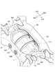
- FIG. 3 is an enlarged partial sectional view of an upper portion of the rear wheel drive device shown in FIG. 2. It is the perspective view which looked at the rear-wheel drive device supported with the support apparatus from the front diagonally downward. It is the perspective view which looked at the rear-wheel drive device supported by the support apparatus from diagonally upward on the rear side. It is sectional drawing of the rear-wheel drive device supported by the support apparatus. It is sectional drawing of the edge part of the rear-wheel drive device supported by the support apparatus. It is sectional drawing which simplified the side edge part of the rear-wheel drive device supported by the support device which concerns on a modification. It is the perspective view which looked at the rear-wheel drive device supported by the support device which concerns on another modification from diagonally upward on the rear side.
- a vehicle 3 shown in FIG. 1 is a hybrid vehicle having a drive device 6 (hereinafter referred to as a front wheel drive device) in which an internal combustion engine 4 and an electric motor 5 are connected in series at the front portion of the vehicle. While power is transmitted to the front wheels Wf via the transmission 7, a drive device 1 (hereinafter referred to as a rear wheel drive device) provided below the floor panel (not shown) at the rear of the vehicle separately from the front wheel drive device 6. Is transmitted to the rear wheels Wr (RWr, LWr).
- the rear wheel drive device 1 includes first and second electric motors 2A and 2B.
- the power of the first electric motor 2A is transmitted to the left rear wheel LWr, and the power of the second electric motor 2B is transmitted to the right rear wheel RWr.
- the electric motor 5 of the front wheel drive device 6 and the first and second electric motors 2A and 2B of the rear wheel drive device 1 are connected to the battery 9 so that power supply from the battery 9 and energy regeneration to the battery 9 are possible. Yes.
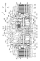
- FIG. 2 is a longitudinal sectional view of the entire rear wheel drive device 1
- FIG. 3 is an enlarged partial sectional view of the upper part of FIG.
- a case 11 that is a housing of the rear wheel drive device 1 includes a central case 11M disposed substantially in the vehicle width direction (hereinafter also referred to as a left-right direction of the vehicle) and left and right sides of the central case 11M so as to sandwich the central case 11M.
- the left side case 11 ⁇ / b> A and the right side case 11 ⁇ / b> B are arranged in a substantially cylindrical shape.
- axles 10A and 10B for the rear wheels Wr, first and second motors 2A and 2B for driving the axle, and first and second motors 2A and 2B for decelerating the driving rotation of the first and second motors 2A and 2B.
- First and second planetary gear speed reducers 12A and 12B as first and second transmissions are arranged side by side on the same rotation axis x.
- the axle 10A, the first electric motor 2A and the first planetary gear speed reducer 12A drive and control the left rear wheel LWr
- the axle 10B, the second electric motor 2B and the second planetary gear speed reducer 12B drive the right rear wheel RWr. Control.
- the axle 10A, the first electric motor 2A and the first planetary gear speed reducer 12A, and the axle 10B, the second electric motor 2B and the second planetary gear speed reducer 12B are arranged symmetrically in the vehicle width direction in the case 11. Yes.
- the side cases 11A and 11B are respectively provided with partition walls 18A and 18B extending radially inward on the central case 11M side. Between the side cases 11A and 11B and the partition walls 18A and 18B, first and first partitions are provided. Two electric motors 2A and 2B are arranged. Further, first and second planetary gear speed reducers 12A and 12B are arranged in a space surrounded by the central case 11M and the partition walls 18A and 18B. As shown in FIG. 2, in this embodiment, the left side case 11A and the central case 11M constitute a first case 11L that houses the first electric motor 2A and the first planetary gear type speed reducer 12A.
- the right side case 11B and the central case 11M constitute a second case 11R that accommodates the second electric motor 2B and the second planetary gear speed reducer 12B.
- the first case 11L includes a left reservoir RL that stores oil as a liquid medium that is used for lubrication and / or cooling of at least one of the first electric motor 2A and the power transmission path
- the second case 11R includes The second electric motor 2B and the right storage part RR that stores oil used for lubrication and / or cooling of at least one of the power transmission paths are provided.
- the rear wheel drive device 1 is provided with a breather device 40 that communicates the inside and outside of the case 11 so that the air inside the case 11 escapes to the outside through the breather chamber 41 so that the air does not become excessively high temperature and pressure.
- the breather chamber 41 is disposed at the upper part in the vertical direction of the case 11, and includes an outer wall of the central case 11M, a first cylindrical wall 43 extending substantially horizontally in the central case 11M on the left side case 11A side, and a right side case.
- a second cylindrical wall 44 extending substantially horizontally on the 11B side, a left and right dividing wall 45 connecting the inner ends of the first and second cylindrical walls 43, 44, and a left side case 11A of the first cylindrical wall 43.
- the first and second cylindrical walls 43, 44 and the left and right dividing walls 45 that form the lower surface of the breather chamber 41 are such that the first cylindrical wall 43 is positioned radially inward from the second cylindrical wall 44, and the left and right dividing walls 45 are A third cylinder that extends from the inner end of the second cylindrical wall 44 to the inner end of the first cylindrical wall 43 while being bent while reducing the diameter, and further extends radially inward and extends substantially horizontally.
- Reach wall 46 The third cylindrical wall 46 is located on the inner side of both outer end portions of the first cylindrical wall 43 and the second cylindrical wall 44 and substantially in the center thereof.
- baffle plates 47A and 47B are provided in the space between the first cylindrical wall 43 and the outer wall of the central case 11M or the space between the second cylindrical wall 44 and the outer wall of the central case 11M as the first planet. It is fixed so as to be separated from the gear type speed reducer 12A or the second planetary gear type speed reducer 12B.
- an external communication path 49 that connects the breather chamber 41 and the outside is connected to the central case 11M on the upper surface in the vertical direction of the breather chamber 41.
- the breather chamber side end portion 49a of the external communication passage 49 is arranged so as to be directed downward in the vertical direction. Accordingly, the oil is prevented from being discharged to the outside through the external communication passage 49.
- the stators 14A and 14B are fixed to the side cases 11A and 11B, respectively, and annular rotors 15A and 15B are provided on the inner peripheral sides of the stators 14A and 14B with respect to the stators 14A and 14B.
- Cylindrical shafts 16A and 16B surrounding the outer periphery of the axles 10A and 10B are coupled to the inner peripheral portions of the rotors 15A and 15B, and the cylindrical shafts 16A and 16B can be relatively rotated coaxially with the axles 10A and 10B.
- the side cases 11A and 11B are supported by end walls 17A and 17B and partition walls 18A and 18B via bearings 19A and 19B. Further, on the outer periphery of one end side of the cylindrical shafts 16A and 16B and on the end walls 17A and 17B, the rotational position information of the rotors 15A and 15B is sent to the controller of the first and second electric motors 2A and 2B (not shown). Resolvers 20A and 20B are provided for feedback.
- the first and second planetary gear speed reducers 12A and 12B mesh with the sun gears 21A and 21B, the ring gears 24A and 24B located on the outer peripheral side of the sun gears 21A and 21B, and the sun gears 21A and 21B and the ring gears 24A and 24B.
- a plurality of planetary gears 22A and 22B, and planetary carriers 23A and 23B that support these planetary gears 22A and 22B, and the driving forces of the first and second electric motors 2A and 2B are input from the sun gears 21A and 21B.
- the decelerated driving force is output to the axles 10A and 10B through the planetary carriers 23A and 23B.
- Sun gears 21A and 21B are formed integrally with cylindrical shafts 16A and 16B.
- the planetary gears 22A and 22B are double pinions having first pinions 26A and 26B having large diameters directly meshed with the sun gears 21A and 21B, and second pinions 27A and 27B having smaller diameters than the first pinions 26A and 26B.
- the first pinions 26A and 26B and the second pinions 27A and 27B are integrally formed in a state of being coaxial and offset in the axial direction.
- the planetary gears 22A and 22B are supported by the pinion shafts 32A and 32B of the planetary carriers 23A and 23B via needle bearings 31A and 31B, and the planetary carriers 23A and 23B have an axially inner end extending radially inward to the axle 10A. 10B and is supported by the partition walls 18A and 18B via bearings 33A and 33B.
- the ring gears 24A and 24B have gear portions 28A and 28B that are meshed with the second pinions 27A and 27B whose inner peripheral surfaces are small in diameter, and small diameters that are smaller than the gear portions 28A and 28B and are opposed to each other at an intermediate position of the case 11.
- the gear portions 28A and 28B face each other in the axial direction with the third cylindrical wall 46 formed at the inner diameter side end of the left and right dividing wall 45 of the central case 11M.
- the outer diameter surfaces of the small diameter portions 29A and 29B are spline-fitted to an inner race 51 of a one-way clutch 50, which will be described later, and the ring gears 24A and 24B are connected to each other so as to rotate integrally with the inner race 51 of the one-way clutch 50. Configured.
- a hydraulic brake constituting braking means for the ring gear 24B 60 is arranged so as to overlap with the first pinion 26B in the radial direction and overlap with the second pinion 27B in the axial direction.
- the hydraulic brake 60 includes a plurality of fixed plates 35 that are spline-fitted to the inner peripheral surface of the second cylindrical wall 44 and a plurality of rotary plates 36 that are spline-fitted to the outer peripheral surface of the gear portion 28B of the ring gear 24B. These plates 35 and 36 are arranged to be fastened and released by an annular piston 37.
- the piston 37 is accommodated in an annular cylinder chamber formed between the left and right dividing walls 45 of the central case 11M and the third cylindrical wall 46, and is further provided with a receiving provided on the outer peripheral surface of the third cylindrical wall 46.
- the elastic member 39 supported by the seat 38 is constantly urged in a direction to release the fixed plate 35 and the rotating plate 36.
- the working chamber S into which oil is directly introduced is defined between the left and right dividing walls 45 and the piston 37, and when the pressure of the oil introduced into the working chamber S exceeds the urging force of the elastic member 39, The piston 37 moves forward (to the right), and the fixed plate 35 and the rotating plate 36 are pressed against each other and fastened. When the urging force of the elastic member 39 exceeds the pressure of the oil introduced into the working chamber S, the piston 37 moves backward (leftward movement), and the fixed plate 35 and the rotating plate 36 are separated and released. .
- the hydraulic brake 60 is connected to an oil pump 70 (see FIG. 4).
- the fixed plate 35 is supported by the second cylindrical wall 44 extending from the left and right dividing walls 45 of the central case 11M constituting the case 11, while the rotating plate 36 is supported by the gear portion 28B of the ring gear 24B. Therefore, when the plates 35 and 36 are pressed by the piston 37, a braking force is applied to the ring gear 24B by the frictional engagement between the plates 35 and 36, and is fixed. When the fastening by the piston 37 is released from this state, the ring gear 24B is allowed to rotate freely.
- the braking force is also applied to the ring gear 24A when the hydraulic brake 60 is fastened, and the ring gear 24A is fixed when the hydraulic brake 60 is released. Free rotation is allowed.
- a space is secured between the coupling portions 30A and 30B of the ring gears 24A and 24B facing each other in the axial direction, and only power in one direction is transmitted to the ring gears 24A and 24B in the space to transmit power in the other direction.
- a one-way clutch 50 is arranged to be shut off.
- the one-way clutch 50 has a large number of sprags 53 interposed between an inner race 51 and an outer race 52.
- the inner race 51 is connected to the small diameter portions 29A, 29B of the ring gears 24A, 24B by spline fitting. It is configured to rotate integrally.
- the outer race 52 is positioned by the third cylindrical wall 46 and is prevented from rotating.
- the one-way clutch 50 is configured to engage and lock the rotation of the ring gears 24A and 24B when the vehicle 3 moves forward with the power of the first and second electric motors 2A and 2B. More specifically, in the one-way clutch 50, when the rotational power in the forward direction (the rotational direction when the vehicle 3 is advanced) on the first and second electric motors 2A, 2B side is input to the rear wheel Wr side. Is engaged, and the first and second electric motors 2A, 2B are in the non-engaged state when the reverse rotational power is input to the rear wheel Wr, and the forward rotational power is applied to the rear wheel Wr. Is disengaged when the first and second electric motors 2A and 2B are input, and the reverse rotational power on the rear wheel Wr side is input to the first and second electric motors 2A and 2B. Is engaged.
- an oil pump 70 as an auxiliary machine is fixed to the front side surface 11c of the central case 11M.
- the oil pump 70 is, for example, a trochoid pump, which is driven by an electric motor (not shown) such as a position sensorless / brushless DC motor and sucks oil stored in the left and right reservoirs RL, RR, and the case 11 and axles 10A, 10B, etc.
- an electric motor not shown
- Each part is lubricated and cooled via lubrication flow paths 79A and 79B provided in each of the mechanical parts.
- the one-way clutch 50 and the hydraulic brake 60 are provided in parallel on the power transmission path between the first and second electric motors 2A and 2B and the rear wheel Wr. . It should be noted that the hydraulic brake 60 is released, weakly engaged, or engaged by the pressure of oil supplied from the oil pump 70 according to the running state of the vehicle and the engaged / disengaged state of the one-way clutch 50. Be controlled.
- the one-way clutch 50 is engaged, so that power transmission is possible, but the hydraulic brake Since 60 is controlled to be in a weakly engaged state, the input of forward rotational power from the first and second electric motors 2A, 2B side temporarily decreases, and the one-way clutch 50 becomes disengaged. Even in this case, it becomes possible to prevent power transmission from being disabled between the first and second electric motors 2A and 2B and the rear wheel Wr.
- the one-way clutch 50 is disengaged and the hydraulic brake 60 is controlled to be in a released state, Over-rotation of the first and second electric motors 2A and 2B is prevented.
- the one-way clutch 50 is disengaged, so the hydraulic brake 60 is controlled to be in the engaged state, so that the reverse direction from the first and second electric motors 2A, 2B side is achieved. Rotational power is output to the rear wheel Wr side, or forward rotational power on the rear wheel Wr side is input to the first and second electric motors 2A, 2B.
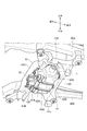
- the rear wheel drive device 1 is arranged to be deviated rearward with respect to the center of the vehicle 3 in the front-rear direction.
- the rear wheel drive device 1 is supported by a subframe 13 supported by a pair of side frames 80 ⁇ / b> A and 80 ⁇ / b> B extending in the front-rear direction.
- the sub-frame 13 includes a pair of sub-side frames 13A and 13B extending in the front-rear direction of the vehicle 3, a front cross frame 13C extending in the left-right direction of the vehicle 3 and fixed to the pair of sub-side frames 13A and 13B, and It is a substantially rectangular frame formed by the rear cross frame 13D, and a space in which the rear wheel drive device 1 is disposed is formed at the center.
- a pair of brackets 81 ⁇ / b> A and 81 ⁇ / b> B are fixed to the front cross frame 13 ⁇ / b> C with bolts at symmetrical positions from the center in the left-right direction of the vehicle 3. Further, support portions 82A and 82B penetrate through the rear cross frame 13D at positions corresponding to the pair of brackets 81A and 81B in the left-right direction.
- a mounting member 85 through which a bolt 84 is inserted via an elastic body 83 is fixed to the support portions 82A and 82B of the brackets 81A and 81B and the rear cross frame 13D.
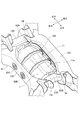
- the case 11 of the rear-wheel drive device 1 supported by the subframe 13 has front fixing portions 91A and 91B formed with female threads on the front side surface 11c so as to correspond to the pair of brackets 81A and 81B.
- Rear fixing portions 92A and 92B formed with female threads are formed on the rear side surface 11d so as to correspond to the support portions 82A and 82B of the rear cross frame 13D.
- two extending portions 93 ⁇ / b> A and 93 ⁇ / b> B extending in the substantially horizontal direction toward the front surface on the upper surface 11 e are provided at the left and right ends of the case 11 in the left and right direction of the rear wheel drive device 1.
- the protrusions 94 are provided so as to be substantially symmetrical with respect to the center, and the protrusions 94 formed at the tips of the extending portions 93A and 93B face the front cross frame 13C with a predetermined gap therebetween.
- a joint flange 13e extends substantially horizontally toward the rear wheel drive device 1 toward the rear wheel drive device 1, and the protrusion 94 is in the front-rear direction with respect to the upper surface 13f of the joint flange 13e, as will be described later. Is disposed on the rear side by the gap S1 and is disposed on the upper side by the gap S2.
- the vehicle 3 is positioned on the side where the rear wheel driving device 1 is disposed, that is, the rear side.
- the rear fixing portions 92A and 92B are formed at higher positions in the vertical direction than the front fixing portions 91A and 91B located on the front side.
- the rear-wheel drive device 1 is arrange
- the rear wheel drive device 1 is fixed to the subframe 13 by fastening the bolts 84 from the outside of the mounting member 85 so as to face the support portions 82A and 82B.
- the extending portions 93A and 93B formed in the case 11 are arranged such that the protruding portion 94 at the tip is rearward by a gap S1 with respect to the joining flange 13e of the front cross frame 13C. It is disposed above the upper surface 13f of the joining flange 13e by a gap S2 and is separated from the joining flange 13e.
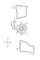
- the rear wheel drive device 1 fixed to the subframe 13 has an imaginary straight line y passing through the centers of the front fixing portions 91A and 91B (center of the bolt holes) and the centers of the rear fixing portions 92A and 92B (center of the bolt holes). Inclined from above to below (lower right in FIG. 6) from the rear side to the front side.
- the virtual straight line y is preferably inclined, for example, by 0.5 ° to 5 ° with respect to the horizontal plane.
- the rear wheel drive device 1 disposed on the rear side of the vehicle 3 is disposed so as to be inclined forward and downward from the rear side toward the front side, thereby greatly affecting the rear wheel drive device 1.
- a side collision hereinafter referred to as a rear collision
- a clockwise moment M shown in FIG. 6 is generated with the rear side facing upward and the front side facing downward.
- the rear wheel drive device 1 is displaced in the direction indicated by the arrow T in FIG. 6, that is, the direction away from the passenger space due to the external force and the moment M at the time of the rear collision.
- the extension portions 93A and 93B are arranged behind the joint flange 13e of the front cross frame 13C by a gap S1 in the front-rear direction and arranged upward by the gap S2.
- the protrusion 94 comes into contact with the upper surface 13f of the joining flange 13e.
- the displacement of the rear wheel drive device 1 is regulated by the joint flange 13e, and the rear wheel drive device 1 is supported by the brackets 81A and 81B and the joint flange 13e.
- the brackets 81A and 81B and the joint flange 13e can share the load from the rear wheel drive device 1, and the brackets 81A and 81B are prevented from being broken.
- the protrusions 94 of the extending portions 93A and 93B and the upper surface 13f of the joining flange 13e do not normally contact but contact only when the rear wheel drive device 1 is displaced by a predetermined amount or more. Vibration or the like of the driving device 1 is not unnecessarily transmitted to the front cross frame 13C on the vehicle side.
- the distance L1 from the rotation axis x of the first and second electric motors 2A and 2B to the tip ends of the rear fixing portions 92A and 92B is larger than the distance L2 from the rotation axis x to the tip portions of the front fixing portions 91A and 91B. Since it is shortened, even if a clockwise moment M occurs when the rear wheel drive device 1 moves, the long side is separated from the occupant space, so that the influence on the occupant space can be further suppressed.
- the extension portions 93A and 93B extending forward from the rear wheel drive device 1 are more than a predetermined amount from the rear side with respect to the rear wheel drive device 1 arranged to be biased to the rear side.
- the rear wheel drive device 1 is displaced more than a predetermined amount due to the external force applied, it is formed so as to contact the upper surface 13f of the joint flange 13e of the front cross frame 13C.
- the displacement of the rear wheel drive device 1 is suppressed, and the rear wheel drive device 1 is suppressed from falling off the subframe 13.
- the load from the rear-wheel drive device 1 can be shared with bracket 81A, 81B and the joining flange 13e, fracture
- the sub frame 13 includes a rear cross frame 13D fixed to the pair of sub side frames 13A and 13B in parallel with the front cross frame 13C. . Furthermore, since the front, rear, left and right four surfaces of the rear wheel drive device 1 are surrounded by the subframe 13, the rigidity in the vicinity of the rear wheel drive device 1 is improved.
- the rear fixing portions 92A and 92B of the rear wheel drive device 1 are formed at positions higher in the vertical direction than the front fixing portions 91A and 91B, the rear side is set to the upper side and the front side is set to the lower side at the time of the rear collision. Since the moment M is generated, the displacement direction of the rear wheel drive device 1 can be set to the direction away from the passenger space, and the safety performance at the time of collision can be improved.
- the two left and right extending portions 93A and 93B are provided on the left and right sides with respect to the center in the left-right direction of the rear wheel drive device 1, the rear wheels are moved after the extending portions 93A and 93B come into contact with the upper surface 13f of the joining flange 13e.
- the posture of the driving device 1 is not easily broken.
- the extension parts 93A and 93B are not limited to two, but may be one or three or more. By disposing the extending portions 93A and 93B so as to be substantially mirror-symmetric with respect to the left and right, the posture of the rear wheel drive device 1 is not easily broken after contact.
- the extending portions 93A and 93B extend in a substantially horizontal direction, the rear wheel drive device 1 is more difficult to drop off after contact. Furthermore, since the extending portions 93A and 93B have the protruding portions 94 that further extend from the tip, the extending portions 93A and 93B are easily caught by the front cross frame 13C, and the rear wheel drive device 1 is more difficult to drop off. Note that the extending portions 93A and 93B are not limited to the substantially horizontal direction, and may be inclined with respect to the vertical direction, and the protruding portion 94 may not be formed.
- the extension portions 93A and 93B of the rear wheel drive device 1 are arranged in the vertical direction of the front cross frame 13C at the time of a rear collision. You may arrange
- the extension portions 93A and 93B of the rear wheel drive device 1 are disposed behind the front cross frame 13C by a gap S1 in the front-rear direction, and the front cross frame 13C. It is disposed above the upper surface 13f by a gap S2 and is separated from the front cross frame 13C.
- the protrusion part 94 is not formed in extension part 93A, 93B is shown.
- the support structure of the rear wheel drive device 1 described above may be applied not only to the rear wheel drive device 1 but also to the front wheel drive device 6.
- extending portions 93A and 93B extending rearward are provided on the upper surface 11e, and the protrusions 94 formed on the leading ends or the leading end portions of the extending portions 93A and 93B are connected to the rear cross frame 13D via a predetermined gap. It arranges so that it may face.
- extension part 93A, 93B extended in the substantially horizontal direction toward the front was illustrated in the upper surface 11e of the left-right direction both ends of the case 11, two extension part 93A, 93B is shown in the left-right direction. You may extend in the mutually opposite direction. That is, as shown in FIG. 9, the extension portion 93B disposed at the left end portion of the case 11 is extended upward and then bent to the left to form a predetermined gap with respect to the sub-side frame 13B. The extension portion 93A disposed at the right end portion of the case 11 is extended upward and then bent rightward so as to be above the sub-side frame 13A by a predetermined gap. To be placed.
- extension portions 93A and 93B By forming the extension portions 93A and 93B in this way, when the rear wheel drive device 1 is displaced in the direction indicated by the arrow T in FIG. 6, that is, the direction away from the passenger space, due to the external force and the moment M at the time of the rear collision, As the rear wheel drive device 1 is displaced downward in the vertical direction, the extension portions 93A and 93B disposed above the sub-side frames 13A and 13B by a predetermined gap are formed on the upper surfaces of the sub-side frames 13A and 13B. Abut.
- bracket 81A, 81B and subside frame 13A, 13B the load from the rear-wheel drive device 1 can be shared by bracket 81A, 81B and subside frame 13A, 13B, and the fracture
- the rear wheel drive device 1 can be reliably brought into contact with the sub-side frames 13A and 13B regardless of the amount of displacement of the rear wheel drive device 1 in the front-rear direction. Further, since the sub-side frames 13A and 13B are provided on the left and right, the posture of the rear wheel drive device 1 is not easily lost after contact.
- this invention is not limited to embodiment mentioned above, A deformation
- a hybrid vehicle has been described as an applicable vehicle.
- the present invention is not limited to this, and may be, for example, an electric vehicle using only a motor as a drive source.
- the rear-wheel drive device 1 containing 1st and 2nd electric motor 2A, 2B and 1st and 2nd planetary gear type reduction gears 12A, 12B was illustrated as a load, one or two The above-described electric motor or transmission may be used, and there is no particular limitation as long as it is a load mounted on a vehicle.
Landscapes
- Engineering & Computer Science (AREA)
- Chemical & Material Sciences (AREA)
- Combustion & Propulsion (AREA)
- Transportation (AREA)
- Mechanical Engineering (AREA)
- Electric Propulsion And Braking For Vehicles (AREA)
- Arrangement Or Mounting Of Propulsion Units For Vehicles (AREA)
- Hybrid Electric Vehicles (AREA)
- Motor Power Transmission Devices (AREA)
Abstract
Description
第1態様は、
車両(例えば、後述の実施形態の車両3)の骨格部材(例えば、後述の実施形態のサブフレーム13)に対し支持手段(例えば、後述の実施形態のブラケット81A、81B、支持部82A、82B)を介して支持される搭載物(例えば、後述の実施形態の後輪駆動装置1)を有する車両であって、
該搭載物は、該搭載物から鉛直方向に対し傾斜して延出し、又は水平方向に延出し、該搭載物に対し所定以上の外力が加わって該搭載物が所定以上変位したときに、前記骨格部材の鉛直方向上方を向く面(例えば、後述の実施形態の上面13f)に当接するよう形成される延出部(例えば、後述の実施形態の延出部93A、93B)を有することを特徴とする。
前記搭載物は前記車両の前後方向中央に対し、一方側(例えば、後述の実施形態の後側)に偏倚して配置され、
前記骨格部材は、前記車両の前後方向に延在する一対の前後骨格部材(例えば、後述の実施形態のサブサイドフレーム13A、13B)と、前記車両の左右方向に延在し、前記一対の前後骨格部材に固定される左右骨格部材(例えば、後述の実施形態の前方クロスフレーム13C)を有し、
前記搭載物は、前記左右骨格部材よりも前記一方側に配置され、
前記延出部は、前記搭載物から前記前後方向の他方側(例えば、後述の実施形態の前側)に延出し、該搭載物に対し前記一方側から所定以上の外力が加わって、前記搭載物が前記他方側に所定以上変位したときに前記左右骨格部材の鉛直方向上方を向く面に当接するよう形成されることを特徴とする。
前記左右骨格部材と並列に前記搭載物を挟むように設けられ、前記一対の前後骨格部材に固定される他の左右骨格部材(例えば、後述の実施形態の後方クロスフレーム13D)を更に備えることを特徴とする。
前記支持手段は、第1支持手段(例えば、後述の実施形態の支持部82A、82B)と第2支持手段(例えば、後述の実施形態のブラケット81A、81B)を有し、
前記搭載物の、前記第1支持手段と前記第2支持手段に固定される固定部(例えば、後述の実施形態の後方固定部92A、92B、前方固定部91A、91B)のうち、相対的に前記一方側寄りに位置する第1固定部(例えば、後述の実施形態の後方固定部92A、92B)が、前記他方側寄りに位置する第2固定部(例えば、後述の実施形態の前方固定部91A、91B)よりも鉛直方向で高い位置に形成されることを特徴とする。
前記延出部は、前記搭載物の左右方向中央に対し、左側および右側にそれぞれ配置される二つの延出部を含むことを特徴とする。
前記二つの延出部は、前記左右方向中央に対し、略対称位置となるよう配置されることを特徴とする。
前記左右骨格部材は、該左右骨格部材から前記搭載物に向かって延出する他の延出部(例えば、後述の実施形態の接合フランジ13e)を有することを特徴とする。
前記骨格部材は、前記車両の前後方向に延在する一対の前後骨格部材(例えば、後述の実施形態のサブサイドフレーム13A、13B)を有し、
前記延出部は、前記搭載物から前記車両の左右方向左側に延出する第1延出部(例えば、後述の実施形態の延出部93B)と、左右方向右側に延出する第2延出部(例えば、後述の実施形態の延出部93A)と、を含み、
該第1延出部及び該第2延出部は、該搭載物に対し所定以上の外力が加わって該搭載物が所定以上鉛直方向下方に変位したときに、前記一対の前後骨格部材の鉛直方向上方を向く面にそれぞれ当接するよう形成されることを特徴とする。
前記延出部は、略水平方向に延出することを特徴とする。
前記延出部は、先端からさらに延出する突起部(例えば、後述の実施形態の突起部94)を有することを特徴とする。
前記搭載物は、前記車両の車輪(例えば、後述の実施形態の後輪Wr)を駆動する電動機(例えば、後述の実施形態の第1及び第2電動機2A、2B)であることを特徴とする。
図1に示す車両3は、内燃機関4と電動機5が直列に接続された駆動装置6(以下、前輪駆動装置と呼ぶ。)を車両前部に有するハイブリッド車両であり、この前輪駆動装置6の動力がトランスミッション7を介して前輪Wfに伝達される一方で、この前輪駆動装置6と別に、車両後部のフロアパネル(不図示)よりも下方に設けられた駆動装置1(以下、後輪駆動装置と呼ぶ。)の動力が後輪Wr(RWr、LWr)に伝達されるようになっている。後輪駆動装置1は、第1及び第2電動機2A、2Bを備え、第1電動機2Aの動力が左後輪LWrに伝達され、第2電動機2Bの動力が右後輪RWrに伝達される。前輪駆動装置6の電動機5と後輪駆動装置1の第1及び第2電動機2A、2Bは、バッテリ9に接続され、バッテリ9からの電力供給と、バッテリ9へのエネルギー回生が可能となっている。
後輪駆動装置1は、図1からも明らかなように、車両3の前後方向中央に対し、後側に偏倚して配置されており、後輪駆動装置1の前方かつ上方が乗員空間C(図6参照。)となっている。後輪駆動装置1は、図4及び図5に示すように、前後方向に延びる一対のサイドフレーム80A、80Bに支持されたサブフレーム13に支持されている。サブフレーム13は、車両3の前後方向に延在する一対のサブサイドフレーム13A、13Bと、車両3の左右方向に延在し一対のサブサイドフレーム13A、13Bに固定される前方クロスフレーム13C及び後方クロスフレーム13Dとにより形成された略矩形状の枠体であり、中央に後輪駆動装置1が配置される空間が形成される。
例えば、本実施形態では、適用車両としてハイブリッド車両について説明したが、本発明はこれに限定されるものでなく、例えば、モータのみを駆動源とする電気自動車であってもよい。
また、上記実施形態では、搭載物として第1及び第2電動機2A、2B及び第1及び第2遊星歯車式減速機12A、12Bを含む後輪駆動装置1を例示したが、1つ又は2つ以上の電動機であってもよく、変速機であってもよく、車両に搭載される搭載物であれば特に限定されるものではない。
2A 第1電動機(電動機)
2B 第2電動機(電動機)
3 車両
13 サブフレーム(骨格部材)
13e 接合フランジ
13A、13B サブサイドフレーム(前後骨格部材)
13C 前方クロスフレーム(左右骨格部材)
13D 後方クロスフレーム(他の左右骨格部材)
13f 上面
81A、81B ブラケット(第2支持手段)
82A、82B 支持部(第1支持手段)
91A、91B 前方固定部(第2固定部)
92A、92B 後方固定部(第1固定部)
93A、93B 延出部
94 突起部
Wr 後輪(車輪)
Claims (11)
- 車両の骨格部材に対し支持手段を介して支持される搭載物を有する車両であって、
該搭載物は、該搭載物から鉛直方向に対し傾斜して延出し、又は水平方向に延出し、該搭載物に対し所定以上の外力が加わって該搭載物が所定以上変位したときに、前記骨格部材の鉛直方向上方を向く面に当接するよう形成される延出部を有することを特徴とする車両。 - 前記搭載物は前記車両の前後方向中央に対し、一方側に偏倚して配置され、
前記骨格部材は、前記車両の前後方向に延在する一対の前後骨格部材と、前記車両の左右方向に延在し、前記一対の前後骨格部材に固定される左右骨格部材を有し、
前記搭載物は、前記左右骨格部材よりも前記一方側に配置され、
前記延出部は、前記搭載物から前記前後方向の他方側に延出し、該搭載物に対し前記一方側から所定以上の外力が加わって、前記搭載物が前記他方側に所定以上変位したときに前記左右骨格部材の鉛直方向上方を向く面に当接するよう形成されることを特徴とする請求項1に記載の車両。 - 前記左右骨格部材と並列に前記搭載物を挟むように設けられ、前記一対の前後骨格部材に固定される他の左右骨格部材を更に備えることを特徴とする請求項2に記載の車両。
- 前記支持手段は、第1支持手段と第2支持手段を有し、
前記搭載物の、前記第1支持手段と前記第2支持手段に固定される固定部のうち、相対的に前記一方側寄りに位置する第1固定部が、前記他方側寄りに位置する第2固定部よりも鉛直方向で高い位置に形成されることを特徴とする請求項3に記載の車両。 - 前記延出部は、前記搭載物の左右方向中央に対し、左側および右側にそれぞれ配置される二つの延出部を含むことを特徴とする請求項1~4のいずれか1項に記載の車両。
- 前記二つの延出部は、前記左右方向中央に対し、略対称位置となるよう配置されることを特徴とする請求項5に記載の車両。
- 前記左右骨格部材は、該左右骨格部材から前記搭載物に向かって延出する他の延出部を有することを特徴とする請求項2~4のいずれか1項に記載の車両。
- 前記骨格部材は、前記車両の前後方向に延在する一対の前後骨格部材を有し、
前記延出部は、前記搭載物から前記車両の左右方向左側に延出する第1延出部と、左右方向右側に延出する第2延出部と、を含み、
該第1延出部及び該第2延出部は、該搭載物に対し所定以上の外力が加わって該搭載物が所定以上鉛直方向下方に変位したときに、前記一対の前後骨格部材の鉛直方向上方を向く面にそれぞれ当接するよう形成されることを特徴とする請求項1に記載の車両。 - 前記延出部は、略水平方向に延出することを特徴とする請求項1~8のいずれか1項に記載の車両。
- 前記延出部は、先端からさらに延出する突起部を有することを特徴とする請求項1~9のいずれか1項に記載の車両。
- 前記搭載物は、前記車両の車輪を駆動する電動機であることを特徴とする請求項1~10のいずれか1項に記載の車両。
Priority Applications (7)
| Application Number | Priority Date | Filing Date | Title |
|---|---|---|---|
| US15/100,539 US9630486B2 (en) | 2013-12-02 | 2014-12-02 | Vehicle |
| MYPI2016701978A MY183774A (en) | 2013-12-02 | 2014-12-02 | Vehicle |
| JP2015551517A JP5938532B2 (ja) | 2013-12-02 | 2014-12-02 | 車両 |
| KR1020167014230A KR101953447B1 (ko) | 2013-12-02 | 2014-12-02 | 차량 |
| EP14868256.0A EP3078524B1 (en) | 2013-12-02 | 2014-12-02 | Vehicle |
| CA2931864A CA2931864A1 (en) | 2013-12-02 | 2014-12-02 | Vehicle |
| CN201480064773.4A CN105793082B (zh) | 2013-12-02 | 2014-12-02 | 车辆 |
Applications Claiming Priority (2)
| Application Number | Priority Date | Filing Date | Title |
|---|---|---|---|
| JP2013249617 | 2013-12-02 | ||
| JP2013-249617 | 2013-12-02 |
Publications (1)
| Publication Number | Publication Date |
|---|---|
| WO2015083699A1 true WO2015083699A1 (ja) | 2015-06-11 |
Family
ID=53273461
Family Applications (1)
| Application Number | Title | Priority Date | Filing Date |
|---|---|---|---|
| PCT/JP2014/081867 Ceased WO2015083699A1 (ja) | 2013-12-02 | 2014-12-02 | 車両 |
Country Status (8)
| Country | Link |
|---|---|
| US (1) | US9630486B2 (ja) |
| EP (1) | EP3078524B1 (ja) |
| JP (1) | JP5938532B2 (ja) |
| KR (1) | KR101953447B1 (ja) |
| CN (1) | CN105793082B (ja) |
| CA (1) | CA2931864A1 (ja) |
| MY (1) | MY183774A (ja) |
| WO (1) | WO2015083699A1 (ja) |
Families Citing this family (9)
| Publication number | Priority date | Publication date | Assignee | Title |
|---|---|---|---|---|
| US9821650B2 (en) * | 2013-03-15 | 2017-11-21 | Linamar Corporation | Hybrid axle assembly for a motor vehicle |
| JP6136949B2 (ja) * | 2014-01-24 | 2017-05-31 | トヨタ自動車株式会社 | ハイブリッド車の制御装置 |
| DE102016006536B4 (de) * | 2016-05-27 | 2018-03-15 | Audi Ag | Elektrische Antriebseinheit für ein Rad eines Kraftfahrzeugs sowie Radaufhängung für die Räder einer Achse eines Kraftfahrzeugs |
| DE102016224199B4 (de) * | 2016-12-06 | 2026-03-05 | Bayerische Motoren Werke Aktiengesellschaft | Hybridfahrzeug |
| JP6791076B2 (ja) * | 2017-09-19 | 2020-11-25 | トヨタ自動車株式会社 | 車両前部構造及び車両用ブラケット |
| WO2021076519A1 (en) * | 2019-10-14 | 2021-04-22 | Omron Robotics & Safety Technologies, Inc. | Mobile robot drive system |
| JP7375665B2 (ja) * | 2020-04-20 | 2023-11-08 | 日産自動車株式会社 | 車体構造 |
| DE102021101730A1 (de) * | 2021-01-27 | 2022-07-28 | Bayerische Motoren Werke Aktiengesellschaft | Strukturelement für ein Fahrgestell eines Kraftfahrzeuges |
| EP4434789A4 (en) * | 2021-11-17 | 2025-02-26 | Nissan Motor Co., Ltd. | ENGINE MOUNTING SYSTEM |
Citations (4)
| Publication number | Priority date | Publication date | Assignee | Title |
|---|---|---|---|---|
| JPH06278476A (ja) * | 1993-03-24 | 1994-10-04 | Toyota Motor Corp | 電気自動車のバッテリキャリア支持構造 |
| JP2009061915A (ja) | 2007-09-06 | 2009-03-26 | Mitsubishi Motors Corp | 電気自動車 |
| JP2011116251A (ja) * | 2009-12-03 | 2011-06-16 | Mitsubishi Motors Corp | ハイブリッド車の電動機の取付構造 |
| JP2013067327A (ja) * | 2011-09-26 | 2013-04-18 | Nissan Motor Co Ltd | 車体後部構造 |
Family Cites Families (47)
| Publication number | Priority date | Publication date | Assignee | Title |
|---|---|---|---|---|
| US4365681A (en) * | 1980-12-22 | 1982-12-28 | General Motors Corporation | Battery support structure |
| US4596299A (en) * | 1984-03-05 | 1986-06-24 | Gkn Automotive Components Inc. | Independent wheel suspension system using constant velocity universal joints in combination with a single prop shaft joint and mounted differentials |
| US4652009A (en) * | 1984-07-31 | 1987-03-24 | Mazda Motor Corporation | Rear suspension system for vehicle |
| JPS6278476A (ja) * | 1985-09-30 | 1987-04-10 | Yamaha Motor Co Ltd | 4サイクルエンジンの点火時期制御方法 |
| DE3710808A1 (de) * | 1987-03-31 | 1988-10-20 | Daimler Benz Ag | Abstuetzung von energieabsorbierend deformierten karosseriestrukturen an einem elastisch gelagerten frontmotor von kraftfahrzeugen |
| JPH0529934Y2 (ja) * | 1987-05-20 | 1993-07-30 | ||
| US5161638A (en) * | 1990-02-23 | 1992-11-10 | Nissan Motor Co., Ltd. | Final drive supporting structure for vehicle |
| US5555950A (en) * | 1992-03-04 | 1996-09-17 | Toyota Jidosha Kabushiki Kaisha | Body structure for electric vehicle |
| JPH0632247A (ja) * | 1992-07-15 | 1994-02-08 | Nissan Motor Co Ltd | 車体下部構造 |
| JP2932133B2 (ja) * | 1993-03-19 | 1999-08-09 | トヨタ自動車株式会社 | 電気自動車の補機部品配置構造 |
| JP2639300B2 (ja) | 1993-03-29 | 1997-08-06 | トヨタ自動車株式会社 | 各種車両の内燃機関の能動型防振装置における駆動制御装置 |
| JPH07117489A (ja) * | 1993-10-20 | 1995-05-09 | Mazda Motor Corp | 電気自動車のバッテリ取付構造 |
| JP3322043B2 (ja) * | 1994-12-14 | 2002-09-09 | トヨタ自動車株式会社 | 車両のパワートレーンの配置構造 |
| JP3381493B2 (ja) * | 1995-12-05 | 2003-02-24 | トヨタ自動車株式会社 | パワートレインの支持装置 |
| JP3698349B2 (ja) * | 1999-02-22 | 2005-09-21 | 本田技研工業株式会社 | 衝撃吸収ストッパ |
| JP3904864B2 (ja) * | 2001-08-28 | 2007-04-11 | 本田技研工業株式会社 | 車体後部構造 |
| JP4122887B2 (ja) * | 2002-08-05 | 2008-07-23 | 日産自動車株式会社 | 車体前部構造 |
| US7588117B2 (en) * | 2003-09-29 | 2009-09-15 | Nissan Motor Co., Ltd. | Structure and method for mounting drive motor |
| US7264277B2 (en) * | 2004-01-22 | 2007-09-04 | Honda Motor Co., Ltd. | Gaseous fuel vehicle rear structure |
| JP4649849B2 (ja) * | 2004-03-02 | 2011-03-16 | トヨタ自動車株式会社 | 蓄電機構の取付構造 |
| JP4779471B2 (ja) * | 2004-10-27 | 2011-09-28 | 日産自動車株式会社 | 車両の前部構造 |
| JP5141026B2 (ja) * | 2006-02-27 | 2013-02-13 | トヨタ自動車株式会社 | 蓄電パックの車載構造 |
| JP4935112B2 (ja) * | 2006-02-28 | 2012-05-23 | トヨタ自動車株式会社 | 蓄電パックの車載構造 |
| JP4092711B1 (ja) * | 2006-11-27 | 2008-05-28 | いすゞ自動車株式会社 | キャブオーバー型車両の前部構造 |
| JP5060220B2 (ja) * | 2007-09-06 | 2012-10-31 | 三菱自動車工業株式会社 | 電気自動車 |
| JP2009096331A (ja) * | 2007-10-17 | 2009-05-07 | Honda Motor Co Ltd | 車両用フロントサブフレーム |
| US8011695B2 (en) * | 2007-12-07 | 2011-09-06 | Toyota Jidosha Kabushiki Kaisha | Car body substructure |
| JP2009166558A (ja) * | 2008-01-11 | 2009-07-30 | Toyota Motor Corp | 車両構造 |
| JP5205073B2 (ja) * | 2008-02-06 | 2013-06-05 | 本田技研工業株式会社 | 自動車の後部車体構造 |
| JP4946969B2 (ja) * | 2008-05-16 | 2012-06-06 | トヨタ自動車株式会社 | 電源装置の保護構造 |
| JP4585585B2 (ja) * | 2008-08-06 | 2010-11-24 | 本田技研工業株式会社 | 車体構造 |
| US8132640B2 (en) * | 2008-08-07 | 2012-03-13 | Honda Motor Co., Ltd. | Frangible mount for a vehicle differential |
| US8632434B2 (en) * | 2009-03-31 | 2014-01-21 | Honda Motor Co., Ltd. | Drive device and vehicle with same |
| JP5077611B2 (ja) * | 2009-05-28 | 2012-11-21 | トヨタ自動車株式会社 | 燃料電池システムおよび車両 |
| DE112009004801B4 (de) * | 2009-05-28 | 2018-08-30 | Toyota Jidosha Kabushiki Kaisha | Brennstoffzellensystem und fahrzeug |
| DE102009042513A1 (de) * | 2009-09-22 | 2011-03-24 | GM Global Technology Operations, Inc., Detroit | Fahrzeug mit Energiespeicherbereich |
| JP5488117B2 (ja) * | 2010-03-30 | 2014-05-14 | マツダ株式会社 | 自動車の駆動力伝達装置およびこれを備えた自動車の下部車体構造 |
| JP5604971B2 (ja) * | 2010-05-17 | 2014-10-15 | 日産自動車株式会社 | 車両の衝突安全装置 |
| JP5071538B2 (ja) * | 2010-09-03 | 2012-11-14 | トヨタ自動車株式会社 | 車両用電池搭載構造 |
| JP5666386B2 (ja) * | 2011-06-08 | 2015-02-12 | 本田技研工業株式会社 | デファレンシャル装置及びそれを備えた車両 |
| JP2013103590A (ja) * | 2011-11-14 | 2013-05-30 | Honda Motor Co Ltd | 電気自動車の前部車体構造 |
| JP5525505B2 (ja) * | 2011-11-14 | 2014-06-18 | 本田技研工業株式会社 | 電動車両の電源装置 |
| JP5906689B2 (ja) * | 2011-11-22 | 2016-04-20 | トヨタ自動車株式会社 | 車両用電池搭載構造 |
| US8917000B2 (en) * | 2011-11-24 | 2014-12-23 | Honda Motor Co., Ltd. | Arrangement structure of connecting conductor connecting inside and outside conductors of motor |
| US8708401B2 (en) * | 2012-03-22 | 2014-04-29 | Ford Global Technologies, Llc | Crash brace for energy management |
| JP5979084B2 (ja) * | 2013-06-05 | 2016-08-24 | トヨタ自動車株式会社 | 車体前部構造 |
| JP6102954B2 (ja) * | 2015-01-16 | 2017-03-29 | マツダ株式会社 | 車両のサブフレーム構造 |
-
2014
- 2014-12-02 US US15/100,539 patent/US9630486B2/en active Active
- 2014-12-02 CA CA2931864A patent/CA2931864A1/en not_active Abandoned
- 2014-12-02 WO PCT/JP2014/081867 patent/WO2015083699A1/ja not_active Ceased
- 2014-12-02 MY MYPI2016701978A patent/MY183774A/en unknown
- 2014-12-02 EP EP14868256.0A patent/EP3078524B1/en not_active Not-in-force
- 2014-12-02 JP JP2015551517A patent/JP5938532B2/ja not_active Expired - Fee Related
- 2014-12-02 KR KR1020167014230A patent/KR101953447B1/ko not_active Expired - Fee Related
- 2014-12-02 CN CN201480064773.4A patent/CN105793082B/zh active Active
Patent Citations (4)
| Publication number | Priority date | Publication date | Assignee | Title |
|---|---|---|---|---|
| JPH06278476A (ja) * | 1993-03-24 | 1994-10-04 | Toyota Motor Corp | 電気自動車のバッテリキャリア支持構造 |
| JP2009061915A (ja) | 2007-09-06 | 2009-03-26 | Mitsubishi Motors Corp | 電気自動車 |
| JP2011116251A (ja) * | 2009-12-03 | 2011-06-16 | Mitsubishi Motors Corp | ハイブリッド車の電動機の取付構造 |
| JP2013067327A (ja) * | 2011-09-26 | 2013-04-18 | Nissan Motor Co Ltd | 車体後部構造 |
Non-Patent Citations (1)
| Title |
|---|
| See also references of EP3078524A4 |
Also Published As
| Publication number | Publication date |
|---|---|
| EP3078524A4 (en) | 2017-08-09 |
| EP3078524B1 (en) | 2019-08-07 |
| US20160297291A1 (en) | 2016-10-13 |
| KR20160093003A (ko) | 2016-08-05 |
| US9630486B2 (en) | 2017-04-25 |
| CN105793082A (zh) | 2016-07-20 |
| CN105793082B (zh) | 2018-09-14 |
| CA2931864A1 (en) | 2015-06-11 |
| KR101953447B1 (ko) | 2019-02-28 |
| JPWO2015083699A1 (ja) | 2017-03-16 |
| JP5938532B2 (ja) | 2016-06-22 |
| EP3078524A1 (en) | 2016-10-12 |
| MY183774A (en) | 2021-03-13 |
Similar Documents
| Publication | Publication Date | Title |
|---|---|---|
| JP5938532B2 (ja) | 車両 | |
| JP5768203B1 (ja) | 車両 | |
| JP5629842B2 (ja) | 車両用駆動装置 | |
| JP2013053737A (ja) | 遊星歯車機構の支持構造 | |
| JP2013147237A (ja) | 車両用駆動装置 | |
| JP5572779B2 (ja) | 車両用駆動装置及び車両用駆動装置の制御方法 | |
| JP5841991B2 (ja) | 輸送機関の駆動装置 | |
| JP2020093664A (ja) | 車両用電気駆動装置 | |
| JP2013215017A (ja) | 車両用駆動装置 | |
| CN105829773B (zh) | 运输机的驱动装置 | |
| JP5820904B2 (ja) | 遊星歯車機構の支持構造 | |
| JP5657068B2 (ja) | 車両用駆動装置 | |
| JP5927006B2 (ja) | 車両用駆動装置 | |
| JP5201080B2 (ja) | ハイブリッド車の駆動機構 | |
| JP2015127177A (ja) | 車両 |
Legal Events
| Date | Code | Title | Description |
|---|---|---|---|
| 121 | Ep: the epo has been informed by wipo that ep was designated in this application |
Ref document number: 14868256 Country of ref document: EP Kind code of ref document: A1 |
|
| ENP | Entry into the national phase |
Ref document number: 2015551517 Country of ref document: JP Kind code of ref document: A |
|
| ENP | Entry into the national phase |
Ref document number: 2931864 Country of ref document: CA |
|
| ENP | Entry into the national phase |
Ref document number: 20167014230 Country of ref document: KR Kind code of ref document: A |
|
| WWE | Wipo information: entry into national phase |
Ref document number: 15100539 Country of ref document: US |
|
| NENP | Non-entry into the national phase |
Ref country code: DE |
|
| REEP | Request for entry into the european phase |
Ref document number: 2014868256 Country of ref document: EP |
|
| WWE | Wipo information: entry into national phase |
Ref document number: 2014868256 Country of ref document: EP |