WO2015083722A1 - 液体材料塗布装置 - Google Patents
液体材料塗布装置 Download PDFInfo
- Publication number
- WO2015083722A1 WO2015083722A1 PCT/JP2014/081930 JP2014081930W WO2015083722A1 WO 2015083722 A1 WO2015083722 A1 WO 2015083722A1 JP 2014081930 W JP2014081930 W JP 2014081930W WO 2015083722 A1 WO2015083722 A1 WO 2015083722A1
- Authority
- WO
- WIPO (PCT)
- Prior art keywords
- control unit
- discharge
- liquid material
- discharge amount
- workpiece
- Prior art date
- Legal status (The legal status is an assumption and is not a legal conclusion. Google has not performed a legal analysis and makes no representation as to the accuracy of the status listed.)
- Ceased
Links
Images

Classifications
-
- G—PHYSICS
- G05—CONTROLLING; REGULATING
- G05D—SYSTEMS FOR CONTROLLING OR REGULATING NON-ELECTRIC VARIABLES
- G05D7/00—Control of flow
- G05D7/06—Control of flow characterised by the use of electric means
- G05D7/0617—Control of flow characterised by the use of electric means specially adapted for fluid materials
- G05D7/0629—Control of flow characterised by the use of electric means specially adapted for fluid materials characterised by the type of regulator means
- G05D7/0635—Control of flow characterised by the use of electric means specially adapted for fluid materials characterised by the type of regulator means by action on throttling means
-
- B—PERFORMING OPERATIONS; TRANSPORTING
- B05—SPRAYING OR ATOMISING IN GENERAL; APPLYING FLUENT MATERIALS TO SURFACES, IN GENERAL
- B05C—APPARATUS FOR APPLYING FLUENT MATERIALS TO SURFACES, IN GENERAL
- B05C11/00—Component parts, details or accessories not specifically provided for in groups B05C1/00 - B05C9/00
- B05C11/10—Storage, supply or control of liquid or other fluent material; Recovery of excess liquid or other fluent material
- B05C11/1002—Means for controlling supply, i.e. flow or pressure, of liquid or other fluent material to the applying apparatus, e.g. valves
- B05C11/1015—Means for controlling supply, i.e. flow or pressure, of liquid or other fluent material to the applying apparatus, e.g. valves responsive to a conditions of ambient medium or target, e.g. humidity, temperature ; responsive to position or movement of the coating head relative to the target
- B05C11/1023—Means for controlling supply, i.e. flow or pressure, of liquid or other fluent material to the applying apparatus, e.g. valves responsive to a conditions of ambient medium or target, e.g. humidity, temperature ; responsive to position or movement of the coating head relative to the target responsive to velocity of target, e.g. to web advancement rate
-
- B—PERFORMING OPERATIONS; TRANSPORTING
- B05—SPRAYING OR ATOMISING IN GENERAL; APPLYING FLUENT MATERIALS TO SURFACES, IN GENERAL
- B05C—APPARATUS FOR APPLYING FLUENT MATERIALS TO SURFACES, IN GENERAL
- B05C13/00—Means for manipulating or holding work, e.g. for separate articles
-
- B—PERFORMING OPERATIONS; TRANSPORTING
- B05—SPRAYING OR ATOMISING IN GENERAL; APPLYING FLUENT MATERIALS TO SURFACES, IN GENERAL
- B05C—APPARATUS FOR APPLYING FLUENT MATERIALS TO SURFACES, IN GENERAL
- B05C5/00—Apparatus in which liquid or other fluent material is projected, poured or allowed to flow on to the surface of the work
- B05C5/02—Apparatus in which liquid or other fluent material is projected, poured or allowed to flow on to the surface of the work the liquid or other fluent material being discharged through an outlet orifice by pressure, e.g. from an outlet device in contact or almost in contact, with the work
- B05C5/0208—Apparatus in which liquid or other fluent material is projected, poured or allowed to flow on to the surface of the work the liquid or other fluent material being discharged through an outlet orifice by pressure, e.g. from an outlet device in contact or almost in contact, with the work for applying liquid or other fluent material to separate articles
- B05C5/0212—Apparatus in which liquid or other fluent material is projected, poured or allowed to flow on to the surface of the work the liquid or other fluent material being discharged through an outlet orifice by pressure, e.g. from an outlet device in contact or almost in contact, with the work for applying liquid or other fluent material to separate articles only at particular parts of the articles
- B05C5/0216—Apparatus in which liquid or other fluent material is projected, poured or allowed to flow on to the surface of the work the liquid or other fluent material being discharged through an outlet orifice by pressure, e.g. from an outlet device in contact or almost in contact, with the work for applying liquid or other fluent material to separate articles only at particular parts of the articles by relative movement of article and outlet according to a predetermined path
-
- B—PERFORMING OPERATIONS; TRANSPORTING
- B05—SPRAYING OR ATOMISING IN GENERAL; APPLYING FLUENT MATERIALS TO SURFACES, IN GENERAL
- B05C—APPARATUS FOR APPLYING FLUENT MATERIALS TO SURFACES, IN GENERAL
- B05C5/00—Apparatus in which liquid or other fluent material is projected, poured or allowed to flow on to the surface of the work
- B05C5/02—Apparatus in which liquid or other fluent material is projected, poured or allowed to flow on to the surface of the work the liquid or other fluent material being discharged through an outlet orifice by pressure, e.g. from an outlet device in contact or almost in contact, with the work
- B05C5/0225—Apparatus in which liquid or other fluent material is projected, poured or allowed to flow on to the surface of the work the liquid or other fluent material being discharged through an outlet orifice by pressure, e.g. from an outlet device in contact or almost in contact, with the work characterised by flow controlling means, e.g. valves, located proximate the outlet
-
- B—PERFORMING OPERATIONS; TRANSPORTING
- B25—HAND TOOLS; PORTABLE POWER-DRIVEN TOOLS; MANIPULATORS
- B25J—MANIPULATORS; CHAMBERS PROVIDED WITH MANIPULATION DEVICES
- B25J11/00—Manipulators not otherwise provided for
-
- B—PERFORMING OPERATIONS; TRANSPORTING
- B25—HAND TOOLS; PORTABLE POWER-DRIVEN TOOLS; MANIPULATORS
- B25J—MANIPULATORS; CHAMBERS PROVIDED WITH MANIPULATION DEVICES
- B25J9/00—Program-controlled manipulators
- B25J9/16—Program controls
- B25J9/1656—Program controls characterised by programming, planning systems for manipulators
- B25J9/1664—Program controls characterised by programming, planning systems for manipulators characterised by motion, path, trajectory planning
-
- B—PERFORMING OPERATIONS; TRANSPORTING
- B25—HAND TOOLS; PORTABLE POWER-DRIVEN TOOLS; MANIPULATORS
- B25J—MANIPULATORS; CHAMBERS PROVIDED WITH MANIPULATION DEVICES
- B25J9/00—Program-controlled manipulators
- B25J9/16—Program controls
- B25J9/1679—Program controls characterised by the tasks executed
-
- B—PERFORMING OPERATIONS; TRANSPORTING
- B25—HAND TOOLS; PORTABLE POWER-DRIVEN TOOLS; MANIPULATORS
- B25J—MANIPULATORS; CHAMBERS PROVIDED WITH MANIPULATION DEVICES
- B25J9/00—Program-controlled manipulators
- B25J9/16—Program controls
- B25J9/20—Program controls fluidic
-
- G—PHYSICS
- G05—CONTROLLING; REGULATING
- G05B—CONTROL OR REGULATING SYSTEMS IN GENERAL; FUNCTIONAL ELEMENTS OF SUCH SYSTEMS; MONITORING OR TESTING ARRANGEMENTS FOR SUCH SYSTEMS OR ELEMENTS
- G05B19/00—Program-control systems
- G05B19/02—Program-control systems electric
- G05B19/18—Numerical control [NC], i.e. automatically operating machines, in particular machine tools, e.g. in a manufacturing environment, so as to execute positioning, movement or co-ordinated operations by means of program data in numerical form
- G05B19/416—Numerical control [NC], i.e. automatically operating machines, in particular machine tools, e.g. in a manufacturing environment, so as to execute positioning, movement or co-ordinated operations by means of program data in numerical form characterised by control of velocity, acceleration or deceleration
-
- B—PERFORMING OPERATIONS; TRANSPORTING
- B05—SPRAYING OR ATOMISING IN GENERAL; APPLYING FLUENT MATERIALS TO SURFACES, IN GENERAL
- B05C—APPARATUS FOR APPLYING FLUENT MATERIALS TO SURFACES, IN GENERAL
- B05C5/00—Apparatus in which liquid or other fluent material is projected, poured or allowed to flow on to the surface of the work
- B05C5/02—Apparatus in which liquid or other fluent material is projected, poured or allowed to flow on to the surface of the work the liquid or other fluent material being discharged through an outlet orifice by pressure, e.g. from an outlet device in contact or almost in contact, with the work
- B05C5/0208—Apparatus in which liquid or other fluent material is projected, poured or allowed to flow on to the surface of the work the liquid or other fluent material being discharged through an outlet orifice by pressure, e.g. from an outlet device in contact or almost in contact, with the work for applying liquid or other fluent material to separate articles
- B05C5/0212—Apparatus in which liquid or other fluent material is projected, poured or allowed to flow on to the surface of the work the liquid or other fluent material being discharged through an outlet orifice by pressure, e.g. from an outlet device in contact or almost in contact, with the work for applying liquid or other fluent material to separate articles only at particular parts of the articles
-
- G—PHYSICS
- G05—CONTROLLING; REGULATING
- G05B—CONTROL OR REGULATING SYSTEMS IN GENERAL; FUNCTIONAL ELEMENTS OF SUCH SYSTEMS; MONITORING OR TESTING ARRANGEMENTS FOR SUCH SYSTEMS OR ELEMENTS
- G05B2219/00—Program-control systems
- G05B2219/30—Nc systems
- G05B2219/45—Nc applications
- G05B2219/45065—Sealing, painting robot
-
- G—PHYSICS
- G05—CONTROLLING; REGULATING
- G05B—CONTROL OR REGULATING SYSTEMS IN GENERAL; FUNCTIONAL ELEMENTS OF SUCH SYSTEMS; MONITORING OR TESTING ARRANGEMENTS FOR SUCH SYSTEMS OR ELEMENTS
- G05B2219/00—Program-control systems
- G05B2219/30—Nc systems
- G05B2219/49—Nc machine tool, till multiple
- G05B2219/49056—Control of flow of fluid or temperature as function of speed for uniform coating
-
- Y—GENERAL TAGGING OF NEW TECHNOLOGICAL DEVELOPMENTS; GENERAL TAGGING OF CROSS-SECTIONAL TECHNOLOGIES SPANNING OVER SEVERAL SECTIONS OF THE IPC; TECHNICAL SUBJECTS COVERED BY FORMER USPC CROSS-REFERENCE ART COLLECTIONS [XRACs] AND DIGESTS
- Y02—TECHNOLOGIES OR APPLICATIONS FOR MITIGATION OR ADAPTATION AGAINST CLIMATE CHANGE
- Y02P—CLIMATE CHANGE MITIGATION TECHNOLOGIES IN THE PRODUCTION OR PROCESSING OF GOODS
- Y02P90/00—Enabling technologies with a potential contribution to greenhouse gas [GHG] emissions mitigation
- Y02P90/02—Total factory control, e.g. smart factories, flexible manufacturing systems [FMS] or integrated manufacturing systems [IMS]
Definitions
- the present invention provides a liquid material that can move a discharge device relative to a workpiece and can automatically generate a command for controlling a discharge amount of a coating device that performs a desired drawing coating (drawing coating) on the workpiece.
- the present invention relates to a coating apparatus.
- the drawing application in the present specification includes not only the case of applying and drawing a single continuous line, but also the case of applying and drawing by intermittent application.
- a discharge device In order to form a liquid material in a predetermined pattern at the time of manufacturing an electronic device, a discharge device called a dispenser is often used. Dispensers are widely used from large equipment to manufacture of small equipment. For example, phosphors and adhesives are linearly applied to flat panel displays typified by liquid crystal, organic EL, and plasma display panels (PDP). It is used for the process or the process of apply
- the application operation using the dispenser is performed by discharging a liquid material from the nozzle while relatively moving the nozzle and the work table according to the application pattern.
- a coating pattern having a corner portion there is a known problem that a line width drawn and disturbed due to a decrease in a relative movement speed in the corner portion when performing a drawing coating.
- an air-type dispenser in which air supplied from a compressed air source is applied to a liquid material in a storage container and discharged from a nozzle communicated with the storage container.
- an air-type dispenser that suppresses the collapse of the pattern at the corner portion during drawing application, for example, in Patent Document 1, in a coating method for drawing a rectangular pattern on a substrate, the nozzle and the substrate at the start point of the corner portion.
- An applicator is disclosed that can suppress the occurrence of vibrations at the corner and can apply an appropriate amount.
- the above control is performed based on pattern data stored in the RAM of the microcomputer, and the corner start and end positions are determined by measuring with a linear scale.
- a relative movement command for moving the relative movement robot in accordance with the coating pattern.
- a discharge amount control command for controlling the discharge amount at each application position on the application pattern.
- the discharge amount control command for example, weakens the air pressure for discharge, shortens the distance between the annular valve seat communicating with the discharge port and the valve body, or weakens the rotational speed of the screw that provides the discharge propulsion force. It is an instruction.
- the relative movement program may be programmed based on characters such as letters, numbers, and symbols, or may be automatically generated by drawing a figure using an applied CAD program.
- the applicant displays a step of displaying a text input screen, a step of displaying a graphic input screen, and movement information of a work device input from the text input screen on a two-dimensional plane on the graphic input screen. From the step of outputting the route and its height information in real time, from the text input screen and / or the figure input screen, the step of outputting the movement information of the work apparatus input from the drawing input screen in real time to the text input screen.
- an object of the present invention is to provide a liquid material coating apparatus capable of reducing the programming work for realizing a desired drawing coating (drawing coating).
- the present invention related to a liquid material application apparatus includes an ejection head for ejecting a liquid material, a work table on which a work is placed, a robot for relatively moving the ejection head and the work table in the XYZ directions, an arithmetic device, and an application program.
- a liquid material application apparatus that draws and applies a liquid material to the work while relatively moving the work and the discharge head.
- a first control unit that relatively moves the discharge head; and a second control unit that controls a discharge amount of the discharge head, wherein the first control unit is speed information on the workpiece of the discharge head. Is output at a predetermined timing, and the second control unit is configured to output the discharge amount based on the speed information output from the first control unit. And having a function of automatically controlled.
- the first control unit and the second control unit may be realized by one physically integrated control unit, or may be realized by two physically separated control units. In some cases.
- the speed information of the ejection head output by the first control unit is a scalar amount of a relative movement speed between the workpiece and the ejection head, and the first control unit or the second control
- the unit has a conversion unit that outputs discharge amount information corresponding to the scalar amount, and the second control unit has a function of automatically controlling the discharge amount based on the discharge amount information output from the conversion unit.
- the conversion unit may further include a conversion table in which discharge amount information corresponding to the scalar amount is defined, or the conversion unit calculates a discharge amount corresponding to the scalar amount. It is good also as providing the conversion type
- the conversion table defines five or more different discharge amounts.
- the said conversion part is a functional module implement
- the first control unit may have a function of synchronizing the discharge amount control of the discharge head by the second control unit and the relative movement of the discharge head.
- the first control unit may be mounted on the robot, and the second control unit may be connected to the robot via a cable.
- the coating apparatus 1 of the present invention includes a dispenser 10 and a robot 20 as main components. Below, each element is explained in detail.
- the dispenser 10 includes a dispense controller 40 and a dispense head 50 as main components.
- the dispense controller 40 includes a storage device and a computing device, and outputs a discharge operation command for controlling the discharge operation of the dispense head 50.
- the dispense head 50 includes a discharge unit 53 and a discharge amount control device 64, and discharges the liquid material from the discharge port 55 under a desired discharge condition based on the discharge operation command signal output from the dispense controller 40.
- the dispenser 10 illustrated in the embodiment is a plunger-type dispenser.
- the plunger system refers to a system in which a liquid material is discharged by the action of a plunger that reciprocates while sliding in the measuring tube.
- the plunger-type dispenser discharges the liquid material by reducing the volume in the measuring tube due to the advance operation of the plunger, and discharges the liquid material on the same principle as a syringe. It is.
- the discharge unit 53 provided in the dispense head 50 of the embodiment includes a measuring tube (not shown), a plunger (not shown), and a nozzle 54 having a discharge port 55 (see FIG. 2).
- the discharge amount control device 64 is a stepping motor (discharge motor) that reciprocates the plunger in the measuring tube. That is, the reciprocation of the plunger is controlled by the rotation of the discharge motor.
- the plunger is retracted to suck the liquid material from the syringe 56.
- the robot 20 is a desktop device that includes an X-axis moving device 21, a Y-axis moving device 22, a robot head 23, a gantry 24, and a robot controller 30.
- the X-axis moving device 21 is a portal device supported by two columns, and uses an X-axis drive source 61 as a drive source.
- a robot head 23 is disposed in the X-axis moving device 21, and the robot head 23 can move to arbitrary coordinates in the X direction.
- the Y-axis moving device 22 is laid on a gantry 24 and uses a Y-axis drive source 62 as a drive source.
- the Y-axis moving device 22 is provided with a table 25, and the table 25 can move to arbitrary coordinates in the Y direction.
- a work 26 is detachably held on the table 25.
- the robot head 23 includes a moving member 28 and a Z-axis drive source 63, and constitutes a Z-axis moving device using the Z-axis drive source 63 as a drive source. That is, the robot head 23 can move the moving member 28 to an arbitrary coordinate in the Z direction by the Z-axis drive source 63. Since the dispensing head 50 is detachably fixed to the moving member 28 made of a plate, the dispensing head 50 can also be moved to arbitrary coordinates in the Z direction by the Z-axis moving device.
- Each of the drive sources 61 to 63 is composed of, for example, a stepping motor, a servo motor, and a linear motor.
- the gantry 24 incorporates a robot controller 30 that controls the operation of the robot.
- the application pattern includes at least one location where the relative movement speed is changed while the liquid material is ejected from the dispense head 50.
- the control unit according to the embodiment includes a robot controller 30 and a dispense controller 40.
- the robot controller 30 is referred to as a first control unit 30, and the dispense controller 40 is referred to as a second control unit 40.
- the first control unit and the second control unit are realized by one control unit that is physically integrated. Sometimes it is done.
- the first control unit 30 includes a storage device 31 that stores a coating program in which a relative movement command is described, and an arithmetic device 32 that executes the coating program.
- the first control unit 30 executes the application program, and transmits a relative movement command to the X-axis moving device 21, the Y-axis moving device 22, and the Z-axis drive moving device 23 via the cable B81. A relative movement with the workpiece 26 is realized.
- the application program a command for moving the XYZ axis moving devices (21 to 23) linearly or curvedly to a specified coordinate, a moving speed setting command for the dispensing head 50, a discharge start command, a discharge end command, and the like are described. ing.
- the application program of the embodiment does not describe a command related to the discharge amount control.
- the application program of the embodiment is processed by an interpreter method.
- the second control unit 40 includes a storage device and an arithmetic device, and transmits a discharge operation command to the dispense head 50 via the cable C82.
- the discharge operation command includes a discharge start command, a discharge end command, and a discharge amount control command.
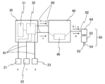
- the second control unit 40 includes a conversion unit 45 realized by software stored in the storage device.
- the conversion unit 45 of the embodiment has a relational expression or conversion table that represents the relationship between the moving speed V of the dispensing head 50 and the control amount D of the discharge amount control device 64.
- the conversion unit 45 applies the moving speed V to the relational expression or the conversion table, and calculates the control amount D for realizing the set line width.
- the moving speed V is a scalar amount of the relative moving speed between the work table 26 and the dispense head 50.
- the control amount D is the rotation speed of the motor (the number of rotations per unit time).
- the relational expression or conversion table needs to be created in advance based on theoretical values or experimental values.
- the relational expression or the conversion table preferably defines five or more different discharge amounts in stages. In order to realize a plurality of application line widths with one application apparatus 1, it is necessary to prepare the same number of relational expressions or conversion tables as the application line widths to be realized.
- the 1st control part 30 and the 2nd control part 40 are electrically connected by cable A80, and can communicate. From the first control unit 30, a discharge start / end command from the application program and the moving speed V of the dispensing head 50 are transmitted to the second control unit 40. Here, the movement speed V of the dispensing head 50 is transmitted to the second control unit 40 when a movement speed change command is issued from the coating program or at predetermined time intervals.
- the acquisition of the moving speed V by the second control unit 40 may be performed by a polling method in which a transmission request is made from the second control unit 40 to the first control unit 30.
- the second control unit 40 receives the moving speed of the dispensing head 50, the optimum control condition of the discharge amount control device 64 is obtained from the above-described relational expression or conversion table of the conversion unit 45.
- the upper part of FIG. 3 is an image diagram of a conversion table showing the control amounts D 1 to D n of the discharge amount control device 64 corresponding to the moving speeds V 1 to V n of the dispense head 50. Since the moving speeds V 1 to V n are described as scalar amounts (absolute values), the same conversion table can be used for acceleration and deceleration.
- the lower part of FIG. 3 is a graph indicating a discharge amount control when the movement speed of the dispensing head 50 is decelerated from V 1 to V n. In the initial state of FIG.
- the dispensing head 50 is moved at the moving speed V 1
- the discharge motor is a discharge amount control device 64 is controlled at a rotational speed of the D 1 per unit time.
- Information on the moving speed of the dispensing head 50 is sent from the first control unit 30 to the second control unit 40 every ⁇ t.
- the converting unit 45 included in the second control unit 40 calculates the corresponding control amount D based on the conversion table.
- the discharge amount control device 64 is decelerated until the rotational speed of the D 2.
- the moving speed decreases in order of V 3 , V 4 ,...
- V n ⁇ 1 a deceleration command is sequentially issued from the second controller 40 in response to this, and the discharge amount control device 64 is also D 3. , D 4 ... D n-1 and the rotational speed is reduced.
- the discharge amount control device 64 maintains the rotational speed D n.
- the discharge amount control device can be controlled by the same method as described above even when it changes nonlinearly.
- the control amount D of the discharge amount control device 64 corresponding to the moving speed V of the dispense head 50 may be selected from the conversion table, and the discharge amount control device 64 may be controlled by the control amount D. It is also possible to use the relational expression and the conversion table together, for example, to use the conversion table for a certain speed range, and to use the relational expression when deviating from the certain speed range.
- the coating apparatus 1 automatically performs a coating operation by executing a coating program created in advance.
- a coating program stored in the storage device 31 of the first control unit is read and executed by the arithmetic device 32, a relative movement command is sent to the X-axis moving device 21, the Y-axis moving device 22, and the Z-axis driving device 23. Is transmitted, and a discharge start / end command is transmitted to the second control unit 40.
- the application program may not include a discharge end command, and may be a specification that ends discharge after a lapse of a certain time from the discharge start command.
- information on the moving speed V of the dispensing head 50 is periodically transmitted to the second control unit 40.
- the information on the moving speed V means moving speed information on the XY plane realized by the X-axis moving device 21 and the Y-axis moving device 22 in the embodiment.
- the second control unit 40 When the second control unit 40 receives the discharge start / end command and the moving speed V information from the first control unit 30, the second control unit 40 transmits a discharge operation command to the dispense head 50.
- a discharge start / end command is described in the application program, but among the discharge operation commands, the discharge amount control command is not described in the application program. That is, the second control unit 40 dynamically generates a discharge amount control command based on the moving speed V of the dispense head 50 described in the application program.
- the discharge amount control device 64 is a stepping motor
- the discharge amount increase command is a command to increase the motor rotation speed (the number of rotations per unit time)
- the discharge amount decrease command is the motor rotation speed.
- the present invention is characterized in that the movement speed of the dispense head and the control of the discharge amount are controlled in real time, but the discharge amount control timing may be slightly shifted depending on the coating conditions. Therefore, the coating apparatus 1 according to a preferred embodiment has a synchronization function for changing the moving speed of the dispensing head and controlling the discharge amount. This synchronization function is realized by uniformly delaying the relative movement command transmitted from the arithmetic unit 32 to the XYZ axis moving devices (21 to 23) for a predetermined time.
- the second control unit 40 acquires information on the moving speed V of the dispense head 50, and a discharge amount control command is transmitted to the dispense head 50, so that the discharge amount actually starts to change. It takes time to complete.
- the calculation device 32 may prefetch the application program and transmit the discharge amount control command before a predetermined time when the moving speed V is changed.
- the discharge amount control device 64 is changed as follows depending on the type of dispenser.
- the discharge volume control device is a regulator, and the discharge volume control parameters are discharge pressure, discharge Pressure application time is reached.
- the discharge amount control device is a motor, and the discharge amount control parameters are the rotation direction, the rotation speed, and the rotation speed.
- the discharge amount control device is an electromagnetic valve, and the discharge amount control parameter is a discharge tact (opening / closing interval of the electromagnetic valve).
- the coating apparatus of the present invention described above, it is not necessary to describe the discharge amount control command according to the moving speed of the discharge apparatus held by the robot, so that the time for creating the coating program can be significantly reduced. It becomes.
- the code amount of the application program is also reduced as a whole, the number of factors causing program errors is reduced, and the debugging time is greatly reduced.
- the operator since the operator only needs to acquire knowledge necessary for programming the relative movement command that determines the operation of the robot, the operator's training period can be shortened.
Landscapes
- Engineering & Computer Science (AREA)
- Robotics (AREA)
- Mechanical Engineering (AREA)
- Physics & Mathematics (AREA)
- General Physics & Mathematics (AREA)
- Automation & Control Theory (AREA)
- Human Computer Interaction (AREA)
- Manufacturing & Machinery (AREA)
- Coating Apparatus (AREA)
- Spray Control Apparatus (AREA)
- Application Of Or Painting With Fluid Materials (AREA)
Abstract
Description
本明細書における線引塗布には、連続する一本の線を塗布描画する場合のみならず、間欠塗布により塗布描画する場合も含まれる。
ディスペンサを用いた塗布作業は、塗布パターンに従いノズルとワークテーブルとを相対移動しながら、ノズルから液体材料を吐出することにより行われる。コーナー部を有する塗布パターンにおいて、線引塗布を行う際には、コーナー部における相対移動速度の低下により、描画形成した線幅に乱れが生じる問題が知られている。
描画塗布時のコーナー部におけるパターンの崩れを抑制するエア式ディスペンサとしては、例えば特許文献1に、基板上に四角形状のパターンを描画する塗布方法において、コーナー部の開始点でノズルと基板との相対速度を減速すると同時にペーストの吐出圧を減圧し、コーナー部を通過後、コーナー部の終了点に至る前にノズルと基板との相対速度を加速すると同時にペーストの吐出圧を増圧することで、コーナー部において振動の発生を抑制し、適正な量の塗布ができる塗布機が開示されている。また上記の制御は、マイクロコンピュータのRAMに格納されたパターンデータに基づき行われ、コーナー開始および終了位置の判定は、リニアスケールにより計測して行われるとしている。
まず、相対移動ロボットを塗布パターンに従って相対移動させるための相対移動指令をプログラミングする必要がある。次に、塗布パターン上の各塗布位置における吐出量を制御する吐出量制御指令をプログラミングする必要がある。吐出量制御指令は、例えば、吐出のためのエア圧力を弱めたり、吐出口と連通する環状弁座と弁体との距離を近めたり、吐出推進力を与えるスクリューの回転速度を弱めたりする命令である。コーナー部などの相対移動速度が変化する場所のXY座標において吐出量を変えるためには、相対移動指令と連動して吐出量制御指令を送信する必要がある。
出願人は、特許文献3において、テキスト入力画面を表示するステップと、図形入力画面を表示するステップと、テキスト入力画面から入力された作業装置の移動情報を、図形入力画面に2次元平面上の経路およびその高さ情報としてリアルタイム出力するステップと、図面入力画面から入力された作業装置の移動情報を、テキスト入力画面にキャラクタベースでリアルタイム出力するステップと、テキスト入力画面および/または図形入力画面から入力された作業装置の移動情報に基づき、作業装置の移動情報を3次元空間上の経路として出力する3D表示画面を表示するステップと、入力された作業装置の(相対)移動プログラムを自動生成するステップとを備えるプログラムを提案している。
かかる課題は、他品種少量生産のニーズに対応する場合には、一層顕著なものとなる。
ここで、上記第一制御部と上記第二制御部とは、物理的に一体である一つの制御部で実現される場合もあれば、物理的に分離された二つの制御部で実現される場合もある。
ここで、上記変換部は、例えば、上記第一または第二制御部が有する記憶装置に格納されたソフトウェアにより実現される機能モジュールである。
上記液体材料塗布装置において、前記第一制御部が、前記ロボットに搭載され、前記第二制御部が、前記ロボットとケーブルを介して接続されることを特徴としてもよい。
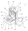
図1に示すように、本発明の塗布装置1は、ディスペンサ10と、ロボット20とを主要な構成要素とする。以下では、各要素を詳説する。
ディスペンサ10は、ディスペンスコントローラ40と、ディスペンスヘッド50とを主要な構成要素とする。
ディスペンスヘッド50は、吐出部53と、吐出量制御装置64とを備え、ディスペンスコントローラ40から出力された吐出動作指令信号に基づき吐出口55から所望の吐出条件で液体材料を吐出する。
実施形態例で例示するディスペンサ10は、プランジャー方式のディスペンサである。ここで、プランジャー方式とは、計量管内を摺動しながら往復移動するプランジャーの作用により液体材料を吐出する方式をいう。別の言い方をすれば、プランジャー方式のディスペンサは、計量管内の容積がプランジャーの進出動作により減少することにより液体材料を吐出するものであり、注射器と同様の原理で液体材料を吐出するものである。
実施形態例のディスペンスヘッド50が備える吐出部53は、図示しない計量管と、図示しないプランジャーと、吐出口55を有するノズル54とを備えている(図2参照)。吐出量制御装置64は、プランジャーを計量管内で往復移動させるステッピングモータ(吐出用モータ)である。すなわち、プランジャーの往復移動は吐出用モータの回転により制御される。より詳細には、吐出用モータの回転数が多くなるほど、プランジャーの進出移動距離が長くなり、吐出用モータの回転速度が速くなるほどプランジャーの前進移動の速度が速くなる。図示しない計量管には、プランジャーを後退させてシリンジ56から液体材料を吸入する。
ロボット20は、X軸移動装置21と、Y軸移動装置22と、ロボットヘッド23と、架台24と、ロボットコントローラ30とを備えた卓上型の装置である。
X軸移動装置21は二本の支柱に支えられた門形の装置であり、X軸駆動源61を駆動源とする。X軸移動装置21にはロボットヘッド23が配設されており、ロボットヘッド23はX方向の任意の座標に移動することが可能である。
Y軸移動装置22は架台24上に敷設されており、Y軸駆動源62を駆動源とする。Y軸移動装置22にはテーブル25が配設されており、テーブル25はY方向の任意の座標に移動することが可能である。テーブル25上にはワーク26が着脱自在に保持される。
各駆動源61~63は、例えば、ステッピングモータ、サーボモータ、リニアモータにより構成される。
架台24には、ロボットの動作を制御するロボットコントローラ30が内蔵されている。
ロボット20により、ディスペンスヘッド50とワーク26とを相対移動させることにより、所望の塗布パターンで塗布描画することが可能である。塗布パターンは、ディスペンスヘッド50から液体材料が吐出しながら相対移動速度を変化させる箇所を少なくとも一つ含んでいる。
実施形態例の制御部は、ロボットコントローラ30と、ディスペンスコントローラ40とから構成される。以下では、ロボットコントローラ30を第一制御部30と呼称し、ディスペンスコントローラ40を第二制御部40と呼称する。なお、第一制御部と第二制御部とが物理的に別体である実施形態例とは異なり、第一制御部と第二制御部とが物理的に一体である一つの制御部で実現される場合もある。
第一制御部30は、塗布プログラムを実行し、X軸移動装置21、Y軸移動装置22およびZ軸駆移動装置23にケーブルB81を介して相対移動指令を送信することで、ディスペンスヘッド50とワーク26との相対移動を実現する。
第二制御部40は、記憶装置と、演算装置とを備え、ケーブルC82を介してディスペンスヘッド50に吐出動作指令を送信する。吐出動作指令には、吐出開始指令、吐出終了指令、および、吐出量制御指令が含まれる。
実施形態例では、吐出量制御装置64が吐出用モータであることから、制御量Dはモータの回転速度(単位時間当たりの回転数)となる。関係式または変換テーブルは、理論値または実験値に基づき予め作成しておく必要がある。関係式または変換テーブルは、5つ以上の異なる吐出量を段階的に定めるものであることが好ましい。なお、一つの塗布装置1で複数の塗布線幅を実現するためには、実現する塗布線幅と同じ数の関係式または変換テーブルを用意することが必要である。
第二制御部40がディスペンスヘッド50の移動速度を受信すると、変換部45の有する前述の関係式または変換テーブルにより吐出量制御装置64の最適制御条件が求められる。
図3の上段は、ディスペンスヘッド50の移動速度V1~Vnに対応する吐出量制御装置64の制御量D1~Dnを示す変換テーブルのイメージ図である。移動速度V1~Vnはスカラー量(絶対値)で記述されているため、加速時と減速時とで同じ変換テーブルを使用することが可能である。
図3の下段は、ディスペンスヘッド50の移動速度がV1からVnに減速する際の吐出量制御を示すグラフである。
図3の初期状態においては、ディスペンスヘッド50が移動速度V1で移動し、吐出量制御装置64である吐出用モータは単位時間当たりD1の回転速度で制御されている。ディスペンスヘッド50の移動速度の情報は、Δt毎に第一制御部30から第二制御部40に送られる。第二制御部40が有する、変換部45は、移動速度Vに変化が生じた場合には、変換テーブルに基づき対応する制御量Dを算出する。
ディスペンスヘッド50の移動速度がV2に低下すると、第二制御部40から減速指令が出され、吐出量制御装置64はD2の回転速度まで減速する。同様に移動速度がV3、V4、・・・・Vn-1と順に低下すると、これに対応して第二制御部40から減速指令が順次出され、吐出量制御装置64もD3、D4・・・・Dn-1と回転速度を減速する。ディスペンスヘッド50の移動速度がVnに達し維持されると、第二制御部40から減速指令が出され、吐出量制御装置64も回転速度をDnに減速する。移動速度がVnを維持される間は、第二制御部40から速度変更指令が出されないので、吐出量制御装置64は回転速度Dnを維持する。
なお、関係式と変換テーブルを併用し、例えば一定の速度範囲には変換テーブルを使用し、一定の速度範囲を逸脱する場合には関係式を使用することも可能である。
塗布装置1は、予め作成された塗布プログラム実行することで自動で塗布作業を実施する。
第一制御部の記憶装置31に格納される塗布プログラムが読み出され、演算装置32で実行されると、X軸移動装置21、Y軸移動装置22およびZ軸駆移動装置23に相対移動指令が送信され、第二制御部40に吐出開始・終了指令が送信される。なお、塗布プログラムには吐出終了指令を含めず、吐出開始指令から一定時間経過後に吐出を終了させる仕様としてもよい。
本発明では、リアルタイム性をもってディスペンスヘッドの移動速度と吐出量の制御がコントロールされる点に特徴があるが、塗布条件によっては吐出量の制御のタイミングが僅かにズレる場合もある。そこで、好ましい形態の塗布装置1は、ディスペンスヘッドの移動速度変化と吐出量制御の同期機能を備えている。
この同期機能は、演算装置32からXYZ軸移動装置(21~23)に送信する相対移動指令を一様に所定時間だけ遅らせることにより実現される。ここで、同期に必要な遅延時間は、第二制御部40がディスペンスヘッド50の移動速度Vの情報を取得し、吐出量制御指令がディスペンスヘッド50に送信され、実際に吐出量が変化し始めるのに要する時間である。或いは、演算装置32が塗布プログラムを先読みし、移動速度Vが変更される所定時間前に吐出量制御指令を送信するようにしてもよい。
実施形態例では、吐出用モータによりプランジャーの進出量が制御されるディスペンサの例を説明したが、ディスペンサは様々な種類のものを使用することが可能である。そして、吐出量制御装置64は、ディスペンサの種類によって例えば次のように代わる。
貯留容器内の液体材料に調圧されたエアを所望時間だけ印加してノズルから吐出を行うエア式ディスペンサの場合は、吐出量制御装置はレギュレータで、吐出量の制御パラメータは、吐出圧力、吐出圧印加時間となる。
ロータリチュービング機構を有するチュービング式ディスペンサの場合は、吐出量制御装置はモータで、吐出量の制御パラメータは、回転方向、回転数、回転速度となる。
ノズルに連通する流路の端部に設けられた弁座に弁体を衝突させてまたは弁体を弁座に衝突する寸前に停止させて液体材料をノズル先端より飛翔吐出させるジェット式ディスペンサの場合は、吐出量制御装置は電磁弁で、吐出量の制御パラメータは、吐出タクト(電磁弁の開閉間隔)となる。
また、オペレータは、ロボットの動作を定める相対移動指令のプログラミングに必要な知識のみを習得すれば足りるので、オペレータの育成期間を短縮することも可能となる。
10:ディスペンサ
20:ロボット
21:X軸移動装置
22:Y軸移動装置
23:ロボットヘッド(Z軸移動装置)
24:架台
25:テーブル
26:ワーク
28:移動部材
30:ロボットコントローラ(第一制御部)
31:記憶装置
32:演算装置
40:ディスペンスコントローラ(第二制御部)
45:変換部
50:ディスペンスヘッド
53:吐出部
54:ノズル
55:吐出口
56:シリンジ
61:X軸駆動源
62:Y軸駆動源
63:Z軸駆動源
64:吐出量制御装置
80:ケーブルA
81:ケーブルB
82:ケーブルC
Claims (7)
- 液体材料を吐出する吐出ヘッドと、
ワークが載置されるワークテーブルと、
吐出ヘッドとワークテーブルとをXYZ方向に相対移動させるロボットと、
演算装置および塗布プログラムを記憶する記憶装置を有する制御部と、を備え、
ワークと吐出ヘッドとを相対移動しながらワークに液体材料を線引塗布する液体材料塗布装置において、
前記制御部が、塗布プログラムに基づき前記ワークと前記吐出ヘッドとを相対移動させる第一制御部と、前記吐出ヘッドの吐出量を制御する第二制御部と、を備えて構成され、
前記第一制御部が、前記吐出ヘッドのワークに対する速度情報を所定のタイミングで出力する機能を有し、
前記第二制御部が、前記第一制御部から出力された前記速度情報に基づき前記吐出量を自動制御する機能を有することを特徴とする液体材料塗布装置。 - 前記第一制御部が出力する前記吐出ヘッドの速度情報が、前記ワークと前記吐出ヘッドとの相対移動速度のスカラー量であり、
前記第一制御部または前記第二制御部が、前記スカラー量に対応する吐出量情報を出力する変換部を有し、
前記第二制御部が、前記変換部から出力された吐出量情報に基づき前記吐出量を自動制御する機能を有することを特徴とする請求項1に記載の液体材料塗布装置。 - 前記変換部が、前記スカラー量に対応する吐出量情報が定められた変換テーブルを備えることを特徴とする請求項2に記載の液体材料塗布装置。
- 前記変換テーブルが、5つ以上の異なる吐出量を定めることを特徴とする請求項3に記載の液体材料塗布装置。
- 前記変換部が、前記スカラー量に対応する吐出量を算出する変換式を備えることを特徴とする請求項2に記載の液体材料塗布装置。
- 前記第一制御部が、前記第二制御部による前記吐出ヘッドの吐出量の制御と前記吐出ヘッドの相対移動とを同期させる機能を有することを特徴とする請求項1ないし5のいずれかに記載の液体材料塗布装置。
- 前記第一制御部が、前記ロボットに搭載され、
前記第二制御部が、前記ロボットとケーブルを介して接続されることを特徴とする請求項1ないし5のいずれかに記載の液体材料塗布装置。
Priority Applications (11)
| Application Number | Priority Date | Filing Date | Title |
|---|---|---|---|
| EP20211442.7A EP3825013B1 (en) | 2013-12-06 | 2014-12-03 | Liquid material application device |
| MYPI2016702059A MY186551A (en) | 2013-12-06 | 2014-12-03 | Liquid material application device |
| US15/101,705 US9952602B2 (en) | 2013-12-06 | 2014-12-03 | Liquid material application device |
| KR1020167014872A KR102326590B1 (ko) | 2013-12-06 | 2014-12-03 | 액체 재료 도포 장치 |
| PL14868304T PL3078427T3 (pl) | 2013-12-06 | 2014-12-03 | Urządzenie do aplikacji ciekłego materiału |
| HK16110879.7A HK1222600B (zh) | 2013-12-06 | 2014-12-03 | 液体材料涂布装置 |
| KR1020217036654A KR102405912B1 (ko) | 2013-12-06 | 2014-12-03 | 액체 재료 도포 장치 |
| CN201480066594.4A CN105792946B (zh) | 2013-12-06 | 2014-12-03 | 液体材料涂布装置 |
| ES14868304T ES2864353T3 (es) | 2013-12-06 | 2014-12-03 | Dispositivo de aplicación de material líquido |
| EP14868304.8A EP3078427B1 (en) | 2013-12-06 | 2014-12-03 | Liquid material application device |
| JP2015551528A JP6622589B2 (ja) | 2013-12-06 | 2014-12-03 | 液体材料塗布装置 |
Applications Claiming Priority (2)
| Application Number | Priority Date | Filing Date | Title |
|---|---|---|---|
| JP2013253655 | 2013-12-06 | ||
| JP2013-253655 | 2013-12-06 |
Publications (1)
| Publication Number | Publication Date |
|---|---|
| WO2015083722A1 true WO2015083722A1 (ja) | 2015-06-11 |
Family
ID=53273484
Family Applications (1)
| Application Number | Title | Priority Date | Filing Date |
|---|---|---|---|
| PCT/JP2014/081930 Ceased WO2015083722A1 (ja) | 2013-12-06 | 2014-12-03 | 液体材料塗布装置 |
Country Status (11)
| Country | Link |
|---|---|
| US (1) | US9952602B2 (ja) |
| EP (2) | EP3825013B1 (ja) |
| JP (2) | JP6622589B2 (ja) |
| KR (2) | KR102405912B1 (ja) |
| CN (2) | CN110000050A (ja) |
| ES (2) | ES2864353T3 (ja) |
| HU (1) | HUE054627T2 (ja) |
| MY (2) | MY186551A (ja) |
| PL (2) | PL3078427T3 (ja) |
| TW (1) | TWI642485B (ja) |
| WO (1) | WO2015083722A1 (ja) |
Cited By (8)
| Publication number | Priority date | Publication date | Assignee | Title |
|---|---|---|---|---|
| JP6349480B1 (ja) * | 2017-05-25 | 2018-06-27 | 武蔵エンジニアリング株式会社 | 液体材料塗布装置および液体材料塗布方法 |
| WO2018199103A1 (ja) | 2017-04-28 | 2018-11-01 | 武蔵エンジニアリング株式会社 | ケーブルユニット、それを備える液体材料供給装置および塗布装置 |
| JP2018199130A (ja) * | 2018-06-04 | 2018-12-20 | 武蔵エンジニアリング株式会社 | 液体材料塗布装置および液体材料塗布方法 |
| WO2019088237A1 (ja) * | 2017-11-02 | 2019-05-09 | 武蔵エンジニアリング株式会社 | 液体材料塗布装置および塗布方法 |
| JP2019072719A (ja) * | 2019-01-21 | 2019-05-16 | 武蔵エンジニアリング株式会社 | 液体材料塗布装置および液体材料塗布方法 |
| WO2020079889A1 (ja) * | 2018-10-17 | 2020-04-23 | 株式会社大気社 | 自動描画システム及び自動描画システムの運転方法 |
| JP2022047709A (ja) * | 2020-09-14 | 2022-03-25 | セーレン株式会社 | インクジェット記録装置及びインクジェット記録装置の調整方法 |
| CN116690599A (zh) * | 2023-05-31 | 2023-09-05 | 中航西安飞机工业集团股份有限公司 | 一种飞机壁板自动涂胶系统和自动涂胶方法 |
Families Citing this family (21)
| Publication number | Priority date | Publication date | Assignee | Title |
|---|---|---|---|---|
| DE102016014946A1 (de) | 2016-12-14 | 2018-06-14 | Dürr Systems Ag | Druckkopf zur Applikation eines Beschichtungsmittels auf ein Bauteil |
| DE102016014944A1 (de) | 2016-12-14 | 2018-06-14 | Dürr Systems Ag | Beschichtungsverfahren und entsprechende Beschichtungseinrichtung |
| DE102016014947A1 (de) | 2016-12-14 | 2018-06-14 | Dürr Systems Ag | Druckkopf zur Applikation eines Beschichtungsmittels |
| DE102016014953A1 (de) | 2016-12-14 | 2018-06-14 | Dürr Systems Ag | Lackieranlage und entsprechendes Lackierverfahren |
| DE102016014952A1 (de) | 2016-12-14 | 2018-06-14 | Dürr Systems Ag | Beschichtungseinrichtung zur Beschichtung von Bauteilen |
| DE102016014919A1 (de) | 2016-12-14 | 2018-06-14 | Dürr Systems Ag | Applikationsvorrichtung und Verfahren zum Applizieren eines Beschichtungsmittels |
| DE102016014955A1 (de) | 2016-12-14 | 2018-06-14 | Dürr Systems Ag | Beschichtungseinrichtung und entsprechendes Beschichtungsverfahren |
| DE102016014948A1 (de) | 2016-12-14 | 2018-06-14 | Dürr Systems Ag | Druckkopf und zugehöriges Betriebsverfahren |
| DE102016014920A1 (de) | 2016-12-14 | 2018-06-14 | Dürr Systems Ag | Druckkopf mit Verschiebe- und/oder Drehmechanik für zumindest eine Düsenreihe |
| DE102016014943A1 (de) | 2016-12-14 | 2018-06-14 | Dürr Systems Ag | Druckkopf mit Temperiereinrichtung |
| DE102016014956A1 (de) | 2016-12-14 | 2018-06-14 | Dürr Systems Ag | Beschichtungseinrichtung und zugehöriges Betriebsverfahren |
| DE102016014951A1 (de) | 2016-12-14 | 2018-06-14 | Dürr Systems Ag | Beschichtungseinrichtung und zugehöriges Betriebsverfahren |
| JP2018192551A (ja) * | 2017-05-16 | 2018-12-06 | セイコーエプソン株式会社 | 制御装置、ロボットおよびロボットシステム |
| CN108580169A (zh) * | 2018-07-05 | 2018-09-28 | 深圳鸿力达智能科技有限公司 | 辊涂点胶机 |
| JP6859992B2 (ja) * | 2018-09-28 | 2021-04-14 | セイコーエプソン株式会社 | 制御方法、ロボット及びロボットシステム |
| CN109542130B (zh) * | 2018-11-07 | 2021-10-08 | 广东震仪智能装备股份有限公司 | 离子喷头流量控制系统及设备 |
| CN110538765B (zh) * | 2019-08-05 | 2021-06-04 | 逸美德科技股份有限公司 | 获得点胶针头的基准坐标的方法、校正方法及校正装置 |
| JP7424626B2 (ja) * | 2020-06-23 | 2024-01-30 | 武蔵エンジニアリング株式会社 | 液体材料吐出装置および液体材料塗布装置 |
| JP7608193B2 (ja) * | 2021-02-01 | 2025-01-06 | 株式会社ジャノメ | 卓上ロボット |
| CN114226164A (zh) * | 2021-12-18 | 2022-03-25 | 惠州市信宇人科技有限公司 | 电极材料的涂布方法、精密程控式涂布供料的呑吐阀及其涂布头 |
| CN114345639A (zh) * | 2022-02-09 | 2022-04-15 | 安徽瑞控智能科技有限公司 | 一种整车控制器的涂胶设备 |
Citations (6)
| Publication number | Priority date | Publication date | Assignee | Title |
|---|---|---|---|---|
| JPH05231546A (ja) * | 1991-03-07 | 1993-09-07 | Fanuc Ltd | 産業用ロボットによるシーリングにおけるシール材流量制御方法 |
| JPH05285434A (ja) * | 1992-04-14 | 1993-11-02 | Omron Corp | 液体吐出装置 |
| JPH11197571A (ja) * | 1998-01-12 | 1999-07-27 | Nordson Kk | 吐出ガンの弁機構の開閉速度制御方法及び装置並びに液状体の吐出塗布方法 |
| JP2001053089A (ja) * | 1999-08-05 | 2001-02-23 | Hitachi Ltd | 半導体装置の製造方法およびそれに使用されるレジン塗布装置 |
| JP2005218971A (ja) | 2004-02-06 | 2005-08-18 | Hitachi Industries Co Ltd | ペースト塗布機と塗布方法 |
| JP2009172452A (ja) | 2008-01-21 | 2009-08-06 | Nippo Kosan Kk | 自動塗布システム、および自動塗布システムの制御方法 |
Family Cites Families (33)
| Publication number | Priority date | Publication date | Assignee | Title |
|---|---|---|---|---|
| US4822647A (en) | 1986-04-23 | 1989-04-18 | Honda Giken Kogyo Kabushiki Kaisha | Coating agent to coating robot, including a method and arrangement for protecting the apparatus from damage due to improper pressures in a supply line |
| JPS62250966A (ja) * | 1986-04-23 | 1987-10-31 | Honda Motor Co Ltd | シ−ル剤塗布装置 |
| JPH0677710B2 (ja) * | 1986-05-15 | 1994-10-05 | 兵神装備株式会社 | 定量塗布装置 |
| JP2620882B2 (ja) * | 1989-06-14 | 1997-06-18 | ファナック株式会社 | シーリング剤塗布方式 |
| JP2711349B2 (ja) * | 1992-08-04 | 1998-02-10 | 川崎重工業株式会社 | 産業用ロボットの制御方法およびそれに用いる制御装置 |
| US5415693A (en) * | 1992-10-01 | 1995-05-16 | Hitachi Techno Engineering Co., Ltd. | Paste applicator |
| US5932012A (en) * | 1995-06-23 | 1999-08-03 | Hitachi Techno Engineering Co., Ltd. | Paste applicator having positioning means |
| JP4344063B2 (ja) * | 2000-03-08 | 2009-10-14 | 中外炉工業株式会社 | ダイコータを用いた塗布方法 |
| KR100506642B1 (ko) | 2001-12-19 | 2005-08-05 | 마츠시타 덴끼 산교 가부시키가이샤 | 디스플레이 패널의 패턴 형성방법 및 형성장치 |
| JP2003225877A (ja) * | 2002-01-30 | 2003-08-12 | Nachi Fujikoshi Corp | 産業用ロボット |
| JP4481576B2 (ja) * | 2003-02-28 | 2010-06-16 | 芝浦メカトロニクス株式会社 | ペースト塗布装置 |
| KR100540633B1 (ko) * | 2003-06-20 | 2006-01-11 | 주식회사 탑 엔지니어링 | 페이스트 도포기 및 그 제어 방법 |
| JP2006081954A (ja) * | 2004-09-14 | 2006-03-30 | Nachi Fujikoshi Corp | シーリング制御装置 |
| JP4497468B2 (ja) | 2004-09-14 | 2010-07-07 | 株式会社不二越 | シーリング・システム |
| ES2264892B1 (es) * | 2005-07-04 | 2007-12-16 | Index Servicios De Ingenieria, S.L. | Sistema automatico de aplicacion de un fluido solidificable. |
| TWI298268B (en) * | 2005-07-08 | 2008-07-01 | Top Eng Co Ltd | Paste dispenser and method of controlling the same |
| WO2007064036A1 (ja) * | 2005-11-30 | 2007-06-07 | Musashi Engineering, Inc. | 液体塗布装置のノズルクリアランス調整方法および液体塗布装置 |
| US8588958B2 (en) * | 2007-09-04 | 2013-11-19 | Musashi Engineering, Inc. | Moving program making-out program and device |
| KR20090031202A (ko) | 2007-09-21 | 2009-03-25 | 이수종 | 채널 화면 분할 방법 및 그 방법에 대한 컴퓨터 프로그램을저장한 기록매체 |
| JP5154879B2 (ja) * | 2007-10-01 | 2013-02-27 | 武蔵エンジニアリング株式会社 | 液体材料の塗布装置、塗布方法およびプログラム |
| DE102008015834A1 (de) * | 2008-03-27 | 2009-10-01 | Inos Automationssoftware Gmbh | Verfahren und Vorrichtung zum automatischen Einbringen oder Auftragen von zähflüssigem Material |
| WO2010146928A1 (ja) * | 2009-06-19 | 2010-12-23 | タツモ株式会社 | 基板用塗布装置 |
| JP5460172B2 (ja) * | 2009-08-11 | 2014-04-02 | 富士フイルム株式会社 | 線描画装置及び線描画方法 |
| JP5166468B2 (ja) * | 2010-03-23 | 2013-03-21 | 株式会社東芝 | ペースト塗布装置及びペースト塗布方法 |
| CN201760380U (zh) * | 2010-05-12 | 2011-03-16 | 常州市武进金顺机电有限公司 | 自动涂胶机 |
| DE102011011545B4 (de) * | 2011-02-17 | 2014-09-11 | Yaskawa Europe Gmbh | Verfahren und Vorrichtung zum Einbringen eines Fluids in eine Fuge |
| CN202010621U (zh) * | 2011-03-16 | 2011-10-19 | 深圳市恒力天科技有限公司 | 高效点胶机 |
| JP2012239962A (ja) * | 2011-05-18 | 2012-12-10 | Panasonic Corp | 塗布方法、および塗布装置 |
| US9962728B2 (en) * | 2012-09-20 | 2018-05-08 | Te Connectivity Corporation | Fluid dispensing machine and method of dispensing fluid |
| CN202800108U (zh) * | 2012-09-24 | 2013-03-20 | 龙岩烟草工业有限责任公司 | 上胶装置及卷烟机 |
| JP6111429B2 (ja) * | 2013-09-13 | 2017-04-12 | パナソニックIpマネジメント株式会社 | 粘性体塗布方法及び粘性体塗布装置 |
| US9374905B2 (en) * | 2013-09-30 | 2016-06-21 | Illinois Tool Works Inc. | Method and apparatus for automatically adjusting dispensing units of a dispenser |
| CN106102933B (zh) * | 2014-03-10 | 2021-03-12 | 武藏工业株式会社 | 涂布装置及涂布方法 |
-
2014
- 2014-12-03 ES ES14868304T patent/ES2864353T3/es active Active
- 2014-12-03 PL PL14868304T patent/PL3078427T3/pl unknown
- 2014-12-03 HU HUE14868304A patent/HUE054627T2/hu unknown
- 2014-12-03 US US15/101,705 patent/US9952602B2/en active Active
- 2014-12-03 MY MYPI2016702059A patent/MY186551A/en unknown
- 2014-12-03 KR KR1020217036654A patent/KR102405912B1/ko active Active
- 2014-12-03 CN CN201910131061.4A patent/CN110000050A/zh active Pending
- 2014-12-03 JP JP2015551528A patent/JP6622589B2/ja active Active
- 2014-12-03 PL PL20211442.7T patent/PL3825013T3/pl unknown
- 2014-12-03 KR KR1020167014872A patent/KR102326590B1/ko active Active
- 2014-12-03 ES ES20211442T patent/ES3056004T3/es active Active
- 2014-12-03 WO PCT/JP2014/081930 patent/WO2015083722A1/ja not_active Ceased
- 2014-12-03 CN CN201480066594.4A patent/CN105792946B/zh active Active
- 2014-12-03 EP EP20211442.7A patent/EP3825013B1/en active Active
- 2014-12-03 EP EP14868304.8A patent/EP3078427B1/en active Active
- 2014-12-03 MY MYPI2020004426A patent/MY203353A/en unknown
- 2014-12-05 TW TW103142348A patent/TWI642485B/zh active
-
2019
- 2019-11-22 JP JP2019211047A patent/JP6990931B2/ja active Active
Patent Citations (6)
| Publication number | Priority date | Publication date | Assignee | Title |
|---|---|---|---|---|
| JPH05231546A (ja) * | 1991-03-07 | 1993-09-07 | Fanuc Ltd | 産業用ロボットによるシーリングにおけるシール材流量制御方法 |
| JPH05285434A (ja) * | 1992-04-14 | 1993-11-02 | Omron Corp | 液体吐出装置 |
| JPH11197571A (ja) * | 1998-01-12 | 1999-07-27 | Nordson Kk | 吐出ガンの弁機構の開閉速度制御方法及び装置並びに液状体の吐出塗布方法 |
| JP2001053089A (ja) * | 1999-08-05 | 2001-02-23 | Hitachi Ltd | 半導体装置の製造方法およびそれに使用されるレジン塗布装置 |
| JP2005218971A (ja) | 2004-02-06 | 2005-08-18 | Hitachi Industries Co Ltd | ペースト塗布機と塗布方法 |
| JP2009172452A (ja) | 2008-01-21 | 2009-08-06 | Nippo Kosan Kk | 自動塗布システム、および自動塗布システムの制御方法 |
Cited By (29)
| Publication number | Priority date | Publication date | Assignee | Title |
|---|---|---|---|---|
| US11456564B2 (en) | 2017-04-28 | 2022-09-27 | Musashi Engineering, Inc. | Cable unit, and liquid material supply device and application device in which said cable unit is used |
| WO2018199103A1 (ja) | 2017-04-28 | 2018-11-01 | 武蔵エンジニアリング株式会社 | ケーブルユニット、それを備える液体材料供給装置および塗布装置 |
| JPWO2018199103A1 (ja) * | 2017-04-28 | 2020-03-12 | 武蔵エンジニアリング株式会社 | ケーブルユニット、それを備える液体材料供給装置および塗布装置 |
| KR20190139882A (ko) | 2017-04-28 | 2019-12-18 | 무사시 엔지니어링 가부시키가이샤 | 케이블 유닛, 이것을 구비하는 액체 재료 공급 장치 및 도포 장치 |
| KR101940598B1 (ko) | 2017-05-25 | 2019-01-21 | 무사시 엔지니어링 가부시키가이샤 | 액체 재료 도포 장치 및 액체 재료 도포 방법 |
| KR101972061B1 (ko) | 2017-05-25 | 2019-04-24 | 무사시 엔지니어링 가부시키가이샤 | 액체 재료 도포 장치 및 액체 재료 도포 방법 |
| KR20210016081A (ko) | 2017-05-25 | 2021-02-10 | 무사시 엔지니어링 가부시키가이샤 | 액체 재료 도포 장치 및 액체 재료 도포 방법 |
| JP6349480B1 (ja) * | 2017-05-25 | 2018-06-27 | 武蔵エンジニアリング株式会社 | 液体材料塗布装置および液体材料塗布方法 |
| TWI665021B (zh) * | 2017-05-25 | 2019-07-11 | Musashi Engineering, Inc. | 液體材料塗佈裝置及液體材料塗佈方法 |
| US20190358662A1 (en) * | 2017-05-25 | 2019-11-28 | Musashi Engineering, Inc. | Liquid material application apparatus and liquid material application method |
| US11396028B2 (en) | 2017-05-25 | 2022-07-26 | Musashi Engineering, Inc. | Liquid material application apparatus and liquid material application method |
| KR20200001594A (ko) | 2017-05-25 | 2020-01-06 | 무사시 엔지니어링 가부시키가이샤 | 액체 재료 도포 장치 및 액체 재료 도포 방법 |
| WO2018216183A1 (ja) * | 2017-05-25 | 2018-11-29 | 武蔵エンジニアリング株式会社 | 液体材料塗布装置および液体材料塗布方法 |
| DE112017000685B4 (de) | 2017-05-25 | 2024-08-29 | Musashi Engineering, Inc. | Flüssigmaterialaufbringungsvorrichtung und Flüssigmaterialaufbringungsverfahren |
| US12162027B2 (en) | 2017-05-25 | 2024-12-10 | Musashi Engineering, Inc. | Liquid material application apparatus and liquid material application method |
| US10786827B2 (en) | 2017-05-25 | 2020-09-29 | Musashi Engineering, Inc. | Liquid material application apparatus and liquid material application method |
| WO2019088237A1 (ja) * | 2017-11-02 | 2019-05-09 | 武蔵エンジニアリング株式会社 | 液体材料塗布装置および塗布方法 |
| JPWO2019088237A1 (ja) * | 2017-11-02 | 2020-11-12 | 武蔵エンジニアリング株式会社 | 液体材料塗布装置および塗布方法 |
| US11001085B2 (en) | 2017-11-02 | 2021-05-11 | Musashi Engineering, Inc. | Liquid material application device and application method |
| JP7098169B2 (ja) | 2017-11-02 | 2022-07-11 | 武蔵エンジニアリング株式会社 | 液体材料塗布装置および塗布方法 |
| JP2018199130A (ja) * | 2018-06-04 | 2018-12-20 | 武蔵エンジニアリング株式会社 | 液体材料塗布装置および液体材料塗布方法 |
| US11214087B2 (en) | 2018-10-17 | 2022-01-04 | Taikisha Ltd. | Automatic drawing system and method of operating automatic drawing system |
| JP2020062605A (ja) * | 2018-10-17 | 2020-04-23 | 株式会社大気社 | 自動描画システム及び自動描画システムの運転方法 |
| WO2020079889A1 (ja) * | 2018-10-17 | 2020-04-23 | 株式会社大気社 | 自動描画システム及び自動描画システムの運転方法 |
| JP2019072719A (ja) * | 2019-01-21 | 2019-05-16 | 武蔵エンジニアリング株式会社 | 液体材料塗布装置および液体材料塗布方法 |
| JP6990927B2 (ja) | 2019-01-21 | 2022-01-12 | 武蔵エンジニアリング株式会社 | 液体材料塗布装置および液体材料塗布方法 |
| JP7491790B2 (ja) | 2020-09-14 | 2024-05-28 | セーレン株式会社 | インクジェット記録装置及びインクジェット記録装置の調整方法 |
| JP2022047709A (ja) * | 2020-09-14 | 2022-03-25 | セーレン株式会社 | インクジェット記録装置及びインクジェット記録装置の調整方法 |
| CN116690599A (zh) * | 2023-05-31 | 2023-09-05 | 中航西安飞机工业集团股份有限公司 | 一种飞机壁板自动涂胶系统和自动涂胶方法 |
Also Published As
| Publication number | Publication date |
|---|---|
| MY203353A (en) | 2024-06-25 |
| EP3078427A1 (en) | 2016-10-12 |
| KR102326590B1 (ko) | 2021-11-12 |
| US9952602B2 (en) | 2018-04-24 |
| KR20210138150A (ko) | 2021-11-18 |
| EP3825013B1 (en) | 2025-09-17 |
| CN110000050A (zh) | 2019-07-12 |
| MY186551A (en) | 2021-07-26 |
| US20160306364A1 (en) | 2016-10-20 |
| ES2864353T3 (es) | 2021-10-13 |
| KR20160094963A (ko) | 2016-08-10 |
| HK1222600A1 (zh) | 2017-07-07 |
| EP3078427A4 (en) | 2017-07-26 |
| JP6622589B2 (ja) | 2019-12-18 |
| PL3825013T3 (pl) | 2026-01-05 |
| PL3078427T3 (pl) | 2021-05-31 |
| CN105792946B (zh) | 2019-03-22 |
| EP3825013A1 (en) | 2021-05-26 |
| ES3056004T3 (en) | 2026-02-17 |
| EP3078427B1 (en) | 2021-02-03 |
| CN105792946A (zh) | 2016-07-20 |
| KR102405912B1 (ko) | 2022-06-03 |
| TW201532675A (zh) | 2015-09-01 |
| JP6990931B2 (ja) | 2022-01-12 |
| JPWO2015083722A1 (ja) | 2017-03-16 |
| HUE054627T2 (hu) | 2021-09-28 |
| TWI642485B (zh) | 2018-12-01 |
| JP2020040066A (ja) | 2020-03-19 |
Similar Documents
| Publication | Publication Date | Title |
|---|---|---|
| JP6622589B2 (ja) | 液体材料塗布装置 | |
| KR102213687B1 (ko) | 액체 재료 도포 장치 및 액체 재료 도포 방법 | |
| CN201625615U (zh) | 精密点涂胶机 | |
| JP6467132B2 (ja) | ロボット、ロボットの制御方法、およびロボットの制御プログラム | |
| JP2009072776A (ja) | 流体材料の量を分注しながら流体ディスペンサを連続的に移動させる方法 | |
| JP6990927B2 (ja) | 液体材料塗布装置および液体材料塗布方法 | |
| HK40005515A (en) | Liquid material application device | |
| HK1222600B (zh) | 液体材料涂布装置 |
Legal Events
| Date | Code | Title | Description |
|---|---|---|---|
| 121 | Ep: the epo has been informed by wipo that ep was designated in this application |
Ref document number: 14868304 Country of ref document: EP Kind code of ref document: A1 |
|
| DPE1 | Request for preliminary examination filed after expiration of 19th month from priority date (pct application filed from 20040101) | ||
| ENP | Entry into the national phase |
Ref document number: 2015551528 Country of ref document: JP Kind code of ref document: A |
|
| REEP | Request for entry into the european phase |
Ref document number: 2014868304 Country of ref document: EP |
|
| WWE | Wipo information: entry into national phase |
Ref document number: 2014868304 Country of ref document: EP |
|
| ENP | Entry into the national phase |
Ref document number: 20167014872 Country of ref document: KR Kind code of ref document: A |
|
| WWE | Wipo information: entry into national phase |
Ref document number: 15101705 Country of ref document: US |
|
| NENP | Non-entry into the national phase |
Ref country code: DE |