WO2015087520A1 - ハンドルヒータ装置 - Google Patents
ハンドルヒータ装置 Download PDFInfo
- Publication number
- WO2015087520A1 WO2015087520A1 PCT/JP2014/006067 JP2014006067W WO2015087520A1 WO 2015087520 A1 WO2015087520 A1 WO 2015087520A1 JP 2014006067 W JP2014006067 W JP 2014006067W WO 2015087520 A1 WO2015087520 A1 WO 2015087520A1
- Authority
- WO
- WIPO (PCT)
- Prior art keywords
- handle
- heater
- terminal
- handle heater
- sensor circuit
- Prior art date
- Legal status (The legal status is an assumption and is not a legal conclusion. Google has not performed a legal analysis and makes no representation as to the accuracy of the status listed.)
- Ceased
Links
Images









Classifications
-
- B—PERFORMING OPERATIONS; TRANSPORTING
- B62—LAND VEHICLES FOR TRAVELLING OTHERWISE THAN ON RAILS
- B62D—MOTOR VEHICLES; TRAILERS
- B62D1/00—Steering controls, i.e. means for initiating a change of direction of the vehicle
- B62D1/02—Steering controls, i.e. means for initiating a change of direction of the vehicle vehicle-mounted
- B62D1/04—Hand wheels
- B62D1/06—Rims, e.g. with heating means; Rim covers
- B62D1/065—Steering wheels with heating and ventilating means
-
- B—PERFORMING OPERATIONS; TRANSPORTING
- B60—VEHICLES IN GENERAL
- B60L—PROPULSION OF ELECTRICALLY-PROPELLED VEHICLES; SUPPLYING ELECTRIC POWER FOR AUXILIARY EQUIPMENT OF ELECTRICALLY-PROPELLED VEHICLES; ELECTRODYNAMIC BRAKE SYSTEMS FOR VEHICLES IN GENERAL; MAGNETIC SUSPENSION OR LEVITATION FOR VEHICLES; MONITORING OPERATING VARIABLES OF ELECTRICALLY-PROPELLED VEHICLES; ELECTRIC SAFETY DEVICES FOR ELECTRICALLY-PROPELLED VEHICLES
- B60L1/00—Supplying electric power to auxiliary equipment of vehicles
- B60L1/02—Supplying electric power to auxiliary equipment of vehicles to electric heating circuits
-
- H—ELECTRICITY
- H05—ELECTRIC TECHNIQUES NOT OTHERWISE PROVIDED FOR
- H05B—ELECTRIC HEATING; ELECTRIC LIGHT SOURCES NOT OTHERWISE PROVIDED FOR; CIRCUIT ARRANGEMENTS FOR ELECTRIC LIGHT SOURCES, IN GENERAL
- H05B1/00—Details of electric heating devices
- H05B1/02—Automatic switching arrangements specially adapted to apparatus ; Control of heating devices
- H05B1/0227—Applications
- H05B1/023—Industrial applications
- H05B1/0236—Industrial applications for vehicles
-
- H—ELECTRICITY
- H05—ELECTRIC TECHNIQUES NOT OTHERWISE PROVIDED FOR
- H05B—ELECTRIC HEATING; ELECTRIC LIGHT SOURCES NOT OTHERWISE PROVIDED FOR; CIRCUIT ARRANGEMENTS FOR ELECTRIC LIGHT SOURCES, IN GENERAL
- H05B3/00—Ohmic-resistance heating
- H05B3/20—Heating elements having extended surface area substantially in a two-dimensional [2D] plane, e.g. plate-heater
- H05B3/34—Heating elements having extended surface area substantially in a two-dimensional [2D] plane, e.g. plate-heater flexible, e.g. heating nets or webs
-
- H—ELECTRICITY
- H05—ELECTRIC TECHNIQUES NOT OTHERWISE PROVIDED FOR
- H05B—ELECTRIC HEATING; ELECTRIC LIGHT SOURCES NOT OTHERWISE PROVIDED FOR; CIRCUIT ARRANGEMENTS FOR ELECTRIC LIGHT SOURCES, IN GENERAL
- H05B6/00—Heating by electric, magnetic or electromagnetic fields
- H05B6/02—Induction heating
-
- H—ELECTRICITY
- H05—ELECTRIC TECHNIQUES NOT OTHERWISE PROVIDED FOR
- H05B—ELECTRIC HEATING; ELECTRIC LIGHT SOURCES NOT OTHERWISE PROVIDED FOR; CIRCUIT ARRANGEMENTS FOR ELECTRIC LIGHT SOURCES, IN GENERAL
- H05B2203/00—Aspects relating to Ohmic resistive heating covered by group H05B3/00
- H05B2203/002—Heaters using a particular layout for the resistive material or resistive elements
- H05B2203/003—Heaters using a particular layout for the resistive material or resistive elements using serpentine layout
-
- H—ELECTRICITY
- H05—ELECTRIC TECHNIQUES NOT OTHERWISE PROVIDED FOR
- H05B—ELECTRIC HEATING; ELECTRIC LIGHT SOURCES NOT OTHERWISE PROVIDED FOR; CIRCUIT ARRANGEMENTS FOR ELECTRIC LIGHT SOURCES, IN GENERAL
- H05B2203/00—Aspects relating to Ohmic resistive heating covered by group H05B3/00
- H05B2203/002—Heaters using a particular layout for the resistive material or resistive elements
- H05B2203/007—Heaters using a particular layout for the resistive material or resistive elements using multiple electrically connected resistive elements or resistive zones
Definitions
- the present invention relates to a handle heater device provided in a steering handle.
- Patent Document 1 discloses a detection device that realizes contact detection of a hand on a handle using a change in the frequency of an oscillation circuit due to a change in capacitance.
- Patent Document 2 discloses a vehicle seat device that detects the presence or absence of a passenger seat using a seat heater.
- the seat heater and the seating detection electrode are used together, thereby eliminating the need for an oscillation circuit and reducing the cost.
- FIG. 12 is a schematic configuration diagram of a vehicle seat device in the prior art (see Patent Document 2).
- the seat heater 8 is provided in the seat of the vehicle seat device 1 and is connected to the seating detection circuit 14 via the coupling capacitor 22. Further, the seat heater 8 is supplied with electric power via the seat heater release switches 11 and 12.
- the seating detection operation by the seating detection circuit 14 is performed when the seat heater release switches 11 and 12 are off.
- the seating detection circuit 14 includes an AC power supply, a band pass filter, a detection / smoothing circuit, an amplifier circuit, an A / D converter, and a microcomputer.
- the band-pass filter can be constituted by a resonance filter that passes a predetermined frequency value output from the AC power supply.
- the AC voltage component extracted from the band-pass filter is detected and smoothed by a detection / smoothing circuit, increased to a predetermined amplitude by an amplifier circuit, converted to a digital signal by an A / D converter, and sent to a microcomputer. Is read.
- the microcomputer determines that the passenger is seated when the magnitude of the read digital signal becomes smaller than a predetermined threshold value.
- Patent Document 2 describes that a heater wire is used as one electrode of a capacitance for detecting seating.
- the electrode in order to use the heater wire as an electrode for detection, the electrode needs to be floating, and seat heater release switches 11 and 12 for disconnecting the seat heater 8 from GND (ground level) are provided. .
- the seat heater release switches 11 and 12 are normally turned on when the heater wire is heated, and are turned off when the seating detection circuit 14 is operated.
- the present invention provides a handle heater device that detects the presence or absence of human hand contact even when the handle heater is energized.
- a handle heater device includes a handle heater that is provided in a steering handle and includes an electrical resistor that generates heat by electrical energy, a first inductor, at least one switch, and a sensor circuit.
- the first inductor is connected in series to the first terminal of the handle heater.
- At least one switch turns the power supply to the handle heater on or off.
- the sensor circuit is electrically connected to the first terminal, and determines whether or not the handle heater is in contact with the detected object based on the capacitance of the handle heater.
- the at least one switch is at least one of a first switch connected in series to the first terminal of the handle heater via a first inductor and a second switch connected in series to the second terminal of the handle heater. is there.
- the power supply to the handle heater is turned on when all of the at least one switch is turned on.
- the impedance on the switch side viewed from the sensor circuit is high impedance in terms of alternating current. Therefore, even when the handle heater is energized, that is, even when the switch is turned on, it is possible to detect the presence or absence of contact of a detected object such as a human hand.
- FIG. 1 is a diagram illustrating an example of a steering handle provided with a handle heater that also serves as hand contact detection in the first embodiment.
- FIG. 2 is a block diagram illustrating a configuration example of the handle heater device according to the first embodiment.
- FIG. 3 is a time chart showing the operation timing of the handle heater device according to the first embodiment.
- FIG. 4 is a block diagram illustrating a configuration example of the sensor circuit according to the first embodiment.
- FIG. 5 is a diagram illustrating a first configuration example of the handle heater according to the first embodiment.
- FIG. 6 is a diagram illustrating a second configuration example of the handle heater according to the first embodiment.
- FIG. 7A is a block diagram illustrating a first modification of the handle heater device according to Embodiment 1.
- FIG. 1 is a diagram illustrating an example of a steering handle provided with a handle heater that also serves as hand contact detection in the first embodiment.
- FIG. 2 is a block diagram illustrating a configuration example of the handle heater device according to the first
- FIG. 7B is a block diagram illustrating another example of the first modification of the handle heater device according to Embodiment 1.
- FIG. 7C is a block diagram showing still another example of the first modification of the handle heater device in the first exemplary embodiment.
- FIG. 8 is a block diagram showing a second modification of the handle heater device in the first embodiment.
- FIG. 9 is a block diagram showing a third modification of the handle heater device in the first embodiment.
- FIG. 10 is a diagram illustrating an example of a steering handle provided with a handle heater that also serves as hand contact detection in the second embodiment.
- FIG. 11A is a block diagram illustrating a configuration example of a handle heater device according to Embodiment 2.
- FIG. 11B is a block diagram illustrating a first modification of the handle heater device according to Embodiment 2.
- FIG. 11C is a block diagram illustrating a second modification of the handle heater device according to Embodiment 2.
- FIG. 11D is a block diagram illustrating a third modification of the handle heater device according to Embodiment 2.
- FIG. 12 is a schematic longitudinal sectional view of a vehicle seat device in the prior art.
- FIG. 13 is an equivalent circuit diagram when the switch in the vehicle seat device in the prior art is off.
- the seating detection circuit 14 detects the magnitude of the electrostatic capacity of the seat heater 8 by applying an AC signal to the seat heater 8 via the coupling capacitance. If the seat heater release switch 12 is on, one end of the coupling capacitor 22 of the seat heater 8 is grounded. Therefore, the seating detection circuit 14 performs the detection operation only when the seat heater release switches 11 and 12 are off. In other words, there is a problem that detection cannot be performed when the seat heater release switches 11 and 12 are in an on state, that is, when the seat heater 8 is in an energized state.
- Patent Document 2 The technology that combines the seat heater in the prior art (Patent Document 2) with a circuit that detects the presence or absence of human contact is also used by the circuit that detects the presence or absence of contact with a human hand. Can be diverted.
- the seat heater / detection circuit is diverted to the handle heater / detection circuit, in addition to the already described problem that contact detection cannot be performed during heat generation of the handle heater, that is, when the handle heater is energized, The following issues arise anew.
- FIG. 13 is an equivalent circuit diagram when the switch in the vehicle seat device in the prior art is off.
- the figure shows the parasitic capacitance C11 when the seat heater release switch 11 is off, the parasitic capacitance C12 when the seat heater release switch 12 is off, and the capacitance C13 of the heater wire whose capacitance changes due to the proximity of the human body. It is shown.
- the seat heater 8 has a specification in which a large current flows in order to quickly warm it. Further, since the on / off control is frequently performed by switching the operation with the seating detection circuit 14, the seat heater 8 is configured by a semiconductor element having a low on-resistance Ron. It is common to be done. An element having a low on-resistance Ron generally has a large parasitic capacitance. In FIG. 13, the capacitance C13 that changes due to the proximity of the human body and the parasitic capacitance C12 of the seat heater release switch 12 are connected in parallel.
- the capacitance change due to the presence / absence of the seating seen from the seating detection circuit 14 is effectively reduced and the sensitivity is lowered.
- the contact area of the handle heater and the human hand is smaller than the contact area of the human body when seated, there is a problem that the sensitivity further decreases.
- the ratio of the capacitance C13 to the parasitic capacitance C12 is small (for example, about 1/10 to 1/100), the sensitivity is low, that is, the S / N ratio is inferior. .
- a handle heater device includes a handle heater that is provided in a steering handle and includes an electric resistor that generates heat by electric energy, a first inductor, It has at least one switch and a sensor circuit.
- the first inductor is connected in series to the first terminal of the handle heater.
- At least one switch turns the power supply to the handle heater on or off.
- the sensor circuit is electrically connected to the first terminal, and determines whether or not the handle heater is in contact with the detected object based on the capacitance of the handle heater.
- the at least one switch is at least one of a first switch connected in series to the first terminal of the handle heater via a first inductor and a second switch connected in series to the second terminal of the handle heater. is there.
- the first inductor is interposed between the connection point of the sensor circuit and the switch, the power supply to the handle heater is turned on by turning on all of the at least one switch.
- the impedance on the switch side viewed from the sensor circuit is high in terms of alternating current. Accordingly, even when the handle heater is energized, that is, even when the switch is turned on, it is possible to detect the presence or absence of contact of a detection object such as a human hand.
- the first inductor is interposed between the sensor circuit and the parasitic capacitance of the switch even when the switch is off, it is possible to suppress a decrease in sensitivity.
- the second terminal may be connected to a switch or a power line without interposing an inductor element.
- the handle heater itself may have a sufficiently large inductance component.
- the inductor element can be omitted, as described above, the second terminal may be connected to the switch or the power supply line without interposing the inductor element. According to this, since the inductor element is not provided between the second terminal and the switch or the power supply line, the configuration can be further simplified.
- the handle heater device further determines the presence or absence of contact between the handle heater and the detected object by a sensor circuit during an effective period synchronized with the power supply to the handle heater being on and off. You may provide the control part which determines an effective period and invalidates a sensor circuit in periods other than an effective period.
- control unit can eliminate the influence due to the transition between the ON state and the OFF state of the power supply to the handle heater, and more accurately detect the presence or absence of human hand contact. In other words, it is possible to eliminate the influence of the transition between the on state and the off state of the switch, and more accurately detect the presence or absence of human hand contact.
- control unit may set a period within a period in which power supply to the handle heater is in an on state as one of the effective periods. According to this, even if the power supply to the handle heater is in an ON state, it is possible to detect the presence or absence of contact of a detection object such as a human hand.
- control unit has an effective period except for a transition period until the power supply to the handle heater is switched from the off state to the stable on state and a transition period until the power supply to the handle heater is switched from the on state to the stable off state. You may make it. According to this, since the control unit operates the sensor circuit while avoiding a transient state due to switching of the power supply to the handle heater, it is possible to avoid the influence of transient noise.
- the handle heater may be configured to include a heating wire connected between the first terminal and the second terminal and wired in a plurality of times. According to this, since the handle heater itself has an inductance, the mounting of the second inductor can be omitted.
- the handle heater may include a planar electric resistor connected between the first terminal and the second terminal. According to this, since the electrostatic capacity of the planar electrical resistor becomes larger, it is possible to further improve the sensitivity to human hand contact.
- the handle heater device may be provided on the steering handle, and may include a plurality of handle heaters including the handle heater and a plurality of first inductors including a first inductor.
- the plurality of first inductors are connected in series to the first terminals of the plurality of handle heaters.
- At least one switch is connected to the first terminal of each of the plurality of handle heaters, to each of the first switch connected to each of the plurality of first inductors, and to each of the second terminals of the plurality of handle heaters. It may be at least one of the connected second switches. According to this, it is possible to detect the contact of a human hand not only during the entire circumference of the steering handle but also during the heating of the steering handle at an arbitrary portion.
- control unit may validate the sensor circuit while switching a plurality of handle heaters in a time division manner.
- the sensor circuit can be shared by a plurality of handle heaters.
- control unit may validate the sensor circuit so as to determine whether or not there is contact with at least two of the plurality of handle heaters at the same time. According to this, it is possible to simultaneously detect the presence or absence of human hand contact with respect to the plurality of handle heaters.
- the electric energy may be DC electric energy. According to this, supply of electric energy can be easily received from a vehicle carrying a battery such as an automobile.
- the sensor circuit outputs an alternating current signal to the steering wheel heater via the first terminal, and detects the level of the signal input from the steering wheel heater via the first terminal, thereby detecting the steering wheel and the detected object.
- the presence or absence of contact with the body may be determined.
- both output and input may be performed at one place of the first terminal, and it is not necessary to separate the input line and the output line, and the circuit configuration can be simplified.
- FIG. 1 is a diagram illustrating an example of a steering handle provided with a handle heater that also serves as hand contact detection in the first embodiment.
- the handle heater 103 is provided in a steering handle such as a vehicle, a ship, an aircraft, a spacecraft, and other vehicles, and is used for both heating of the steering handle and hand contact determination.
- the handle heater 103 is composed of an electric resistor that generates heat by electric energy supplied from the power source VDC.
- two steering wheel heaters 103 are provided for one steering handle, but there may be one or three or more.
- the handle heater 103 may be built in the steering handle or may be added as an option.
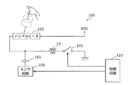
- FIG. 2 is a block diagram illustrating a configuration example of the handle heater device 100 according to the first embodiment.
- the handle heater device 100 includes a switch 101, an inductor La, an inductor Lb, a handle heater 103, a coupling capacitor 105, a sensor circuit 106, and a control circuit 107.
- the configuration example of FIG. 2 corresponds to one of the two handle heaters 103 of FIG. That is, in FIG. 1, it is assumed that two handle heater devices are provided.
- a switch 101 is a transistor switch that is connected in series to the first terminal of the handle heater 103 via the inductor Lb, and that turns on or off the power supply to the handle heater 103, and a switch control signal from the control circuit 107. Turn on and off according to.
- the inductor La is an inductive element (for example, a coil) having inductance, is connected in series to the second terminal of the handle heater 103, and is connected to the power line of the power source VDC.
- the power source VDC is a battery or the like of a vehicle (for example, an automobile) having a steering handle, and supplies direct current electric energy.
- the output voltage of the power source VDC is a DC voltage, for example, 12V or 24V.
- the inductor Lb is connected in series to the first terminal of the handle heater 103 and is connected to a non-grounded terminal of the switch 101.
- the handle heater 103 has inductors La and Lb connected in series at both ends thereof, and is supplied with DC power when the switch 101 is on.
- the handle heater 103 is, for example, a planar heating element that includes a heating wire that is wired in multiple turns and is wound around or incorporated in the steering handle.
- the coupling capacitor 105 is a capacitive element that cuts the direct current and electrically connects the first terminal of the handle heater 103 and the sensor circuit 106, that is, couples in an alternating manner.
- the sensor circuit 106 makes contact between the handle heater and the human hand based on the capacitance between the handle heater 103 and the human hand. The presence or absence of is determined. Specifically, the sensor circuit 106 outputs an AC signal (for example, a periodic pulse signal) to the handle heater 103 via the coupling capacitor 105, and as a result, the static between the handle heater 103 and the human hand is output. The presence or absence of contact between the handle heater 103 and a human hand is determined by determining the level of an AC signal (for example, a smoothed level) determined according to the magnitude of the electric capacity. The operation of the sensor circuit 106 is controlled by the control circuit 107 (for example, controlled by an enable signal).
- the control circuit 107 for example, controlled by an enable signal
- the inductor Lb is interposed between the sensor circuit 106 and the switch 101, even when the switch 101 is on, the impedance on the switch 101 side viewed from the sensor circuit 106 is high impedance in terms of alternating current. Therefore, even when the handle heater 103 is energized by the ON state of the switch 101, the sensor circuit 106 can detect the presence or absence of human hand contact.
- the sensor circuit 106 detects the presence or absence of a human hand contact.
- the inductor Lb is interposed between the sensor circuit 106 and the parasitic capacitance of the switch 101 when the switch 101 is off, a decrease in sensitivity can be suppressed.
- the control circuit 107 controls the operation of the switch 101 and the sensor circuit 106.
- the control circuit 107 controls the sensor circuit 106 to operate within a period in which the switch 101 is on and off.
- FIG. 3 is a time chart showing an operation timing example of the handle heater device 100 according to the first embodiment.
- the period indicated as ON means that the handle heater 103 is energized, and the period indicated as OFF means that the handle heater 103 is not energized.
- a signal indicating whether the handle heater 103 is energized or not energized is a switch control signal for controlling on / off of the switch 101.
- a period indicated as ON means that the sensor circuit 106 is operating, and a period indicated as OFF means that the sensor circuit is not operating.
- a signal indicating whether the sensor circuit 106 is operating or not operating is an enable signal for controlling the operation of the sensor circuit 106.
- the above switch control signal and enable signal are generated by the control circuit 107.
- the control circuit 107 switches from the OFF state to the stable ON state, the transition period until the output of the sensor circuit is stabilized, and the ON state to the stable OFF state.
- the sensor circuit 106 is controlled to operate except for a transition period until the output of the circuit is stabilized.
- control circuit 107 always operates the sensor circuit 106 regardless of the ON period or the OFF period, instead of controlling that the sensor circuit 106 is operating during the ON period and the sensor circuit is stopped during the OFF period.
- the determination result of the sensor circuit 106 may be validated during the ON period and invalidated during the OFF period. That is, the control circuit 107 may control a valid period (for example, the lower ON period in FIG. 3) in which the determination result of the sensor circuit 106 is valid without invalidating the control circuit 107. In other words, the control circuit 107 may perform control to invalidate or ignore the determination result of the sensor circuit 106 in a period other than the valid period (for example, the lower OFF period in FIG. 3).
- the enable signal is used as a mask signal that masks the determination result in a period other than the valid period and does not mask the determination result in the valid period.
- the control circuit 107 has an effective period synchronized with the ON state and the OFF state of the power supply to the handle heater 103 as shown in the lower part of FIG.
- An effective period for determining the presence or absence of contact with the detection body is determined.
- the control circuit 107 sets a period within the period in which the power supply to the handle heater 103 is on as one of the effective periods.
- the control circuit 107 is effective except for a transition period until the power supply to the handle heater 103 is switched from the off state to the stable on state and a transition period until the power supply to the handle heater 103 is switched from the on state to the stable off state. Period.
- the control circuit 107 invalidates the sensor circuit 106 during a period other than the valid period.
- the invalidation of the sensor circuit 106 may be control for stopping the operation of the sensor circuit 106, or control in which the control circuit 107 ignores the determination result even when the sensor circuit 106 is operating, that is, the determination result is Masking control may be used.
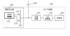
- FIG. 4 is a block diagram illustrating a configuration example of the sensor circuit 106 according to the first embodiment.
- the sensor circuit 106 includes a charge injection unit 130, a smoothing circuit 140, an analog-digital (AD) converter 150, and a determination unit 160.
- the charge injection unit 130 includes a pulse generator 131 and switches 132 and 133 and injects charges into the handle heater 103 via the coupling capacitor 105.
- the pulse generator 131 generates an AC signal.
- the switch 132 is repeatedly turned on and off according to a periodic pulse.
- the switch 133 is turned off when the switch 132 is turned on and turned on when the switch 132 is turned off.
- Smoothing circuit 140 smoothes the level of the AC signal.
- the AD converter 150 converts the smoothed signal level into a digital value.
- the determination unit 160 compares the digital value from the AD converter 150 with a threshold value. If the digital value exceeds the threshold value, that is, if the capacitance is small, the determination unit 160 determines that there is no contact. If the value does not exceed the threshold value, that is, if the capacitance is large, it is determined that the contact has occurred.
- the threshold value is determined in advance by experiments, actual measurements, and the like, and is updated to a new value from repeated contact and non-contact of a human hand and stored in the determination unit 160.
- the determination unit 160 determines the distance between the steering wheel and the human hand according to the difference between the digital value and the threshold value when there is no contact.
- a table indicating the correspondence between the digital value and the distance is created in advance and stored in the determination unit 160.
- the determination unit 160 performs determination as a contact sensor and determination as a proximity sensor.
- FIG. 5 is a diagram illustrating a first configuration example of the handle heater 103 according to the first embodiment.
- the handle heater 103 in the figure includes a support 111 and a heating wire 110 as an electric resistor.
- the support 111 is made of, for example, a nonwoven fabric.
- the handle heater 103 constitutes a flexible planar heating element by the support 111 and the heating wire 110, and is built in or added around the steering handle.
- the heating wire 110 is laid back and forth multiple times so as to generate heat in a planar shape.
- the handle heater 103 further includes a connection member 111a.
- the first terminal to which the inductor Lb is connected may be in the middle or the tip of the lead wire connected to the connection member 111a, or may be the connection member 111a.
- the inductor La can be omitted.
- FIG. 6 is a diagram illustrating a second configuration example of the handle heater 103 according to the first embodiment.
- the handle heater 103 in FIG. 6 includes a planar electrical resistor 112 as an electrical resistor instead of the heating wire 110 in FIG.
- the handle heater 103 can further improve the sensitivity with a larger electrostatic capacity than the configuration of FIG. 5.
- the inductor La may be connected without being omitted.
- FIG. 7A is a block diagram illustrating a first modification of the handle heater device 100 according to the first exemplary embodiment.
- the handle heater device 100 illustrated in FIG. 7A is different from that illustrated in FIG. 2 in that the inductor La is deleted and the second terminal of the handle heater 103 is connected to the power source VDC.
- the handle heater 103 has an inductance component, the inductor La does not have to be provided as shown in FIG. 7A.
- This first modification is suitable for the first configuration example of the handle heater having an inductance component, that is, the handle heater 103 shown in FIG.
- FIG. 7B is a block diagram illustrating another example of the first modification of the handle heater device 100 according to the first exemplary embodiment.
- the handle heater device 100 shown in FIG. 7B is different from that shown in FIG. 7A in that the switch 101 is deleted and a switch 102 connected in series to the second terminal of the handle heater 103 is added.
- Another example of the first modification is also suitable for the first configuration example of the handle heater 103 shown in FIG.
- FIG. 7C is a block diagram illustrating still another example of the first modification of the handle heater device 100 according to the first embodiment.
- the handle heater device 100 shown in FIG. 7C is different from that shown in FIG. 7A in that a switch 102 connected in series to the second terminal of the handle heater 103 is added.
- Another example of the first modification is also suitable for the first configuration example of the handle heater 103 shown in FIG.
- the handle heater device 100 only needs to include at least one switch. That is, at least one switch may be at least one of the switch 101 connected in series to the first terminal of the handle heater 103 via the inductor Lb and the switch 102 connected in series to the second terminal of the handle heater 103.
- the handle heater device 100 includes two switches 101 and 102, when supplying direct current to the handle heater 103, that is, when turning on the power supply to the handle heater 103, the control circuit 107 is Both the switch 101 and the switch 102 connected in series are turned on.
- the control circuit 107 when the direct current supplied to the handle heater 103 is cut off, that is, when the power supply to the handle heater 103 is turned off, the control circuit 107 includes the switch 101 and the switch 102 connected in series. Any one of the switches or all the switches may be turned off.
- the second terminal may be connected to a switch or a power line without interposing an inductor element. Further, the connection between the power source VDC and the ground may be reversed.
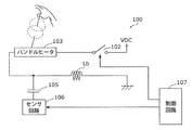
- FIG. 8 is a block diagram showing a second modification of the handle heater device in the first embodiment.
- the handle heater device 100 shown in FIG. 8 is different from FIG. 2 in that the connection between the power source VDC and the ground potential is reversed.
- This second modification is suitable for both the first and second configuration examples of the handle heater 103 shown in FIGS.
- FIG. 9 is a block diagram showing a third modification of the handle heater device in the first embodiment.
- the handle heater device 100 shown in FIG. 9 is different from the first modification shown in FIG. 7A in that the connection between the power source VDC and the ground potential is reversed.
- This third modification is suitable for the first configuration example of the handle heater 103 shown in FIG.
- the handle heater device includes the inductor La at the first terminal of the handle heater 103 and the inductor Lb at the second terminal as shown in FIG.
- a sensor circuit 106 that detects contact and proximity of a human hand is connected between one end of the handle heater 103 and the inductor Lb.
- the sensor circuit 106 applies, for example, an AC signal as a detection signal to the handle heater 103 to detect the magnitude or change of the coupling capacitance.
- the inductor Lb functions as a high impedance to the detection signal when the handle heater 103 is used as a sensor, that is, one electrode of capacitance, and therefore, regardless of whether the switch 101 is on or off, Enable detection.
- the inductor Lb reduces the influence of the parasitic capacitance of the switch 101.
- the inductance values of the inductors La and Lb values that can provide practically sufficient sensitivity with the detection signal output from the sensor circuit 106 may be selected. For example, when the frequency of the detection signal output from the sensor circuit 106 is 5 MHz, the inductance values of the inductors La and Lb can be selected to be 10 ⁇ H (microhenry).
- the inductor La on the side to which the sensor circuit 106 is not connected is the inductance component of the handle heater 103 itself. It can be substituted.
- control circuit 107 switches the switch 101 on or off based on the detection result of a temperature sensor that measures the temperature of the handle heater 103 (not shown) so as to maintain the temperature of the handle heater 103 at a constant temperature. You may control it.
- a temperature sensor that measures the temperature of the handle heater 103 (not shown) so as to maintain the temperature of the handle heater 103 at a constant temperature. You may control it.
- the switch 101 is turned on or off, a transient noise component other than the detection signal is detected by the sensor circuit 106. Therefore, the sensing component is temporarily stopped or the influence of the power supply component is reduced by performing data discarding or the like. It can be avoided. For this reason, as shown in FIG. 3, the ON / OFF of the sensor circuit 106 and the handle heater 103 is preferably synchronized by the control circuit 107.
- FIG. 10 is a diagram illustrating an example of a steering handle provided with a handle heater that also serves as hand contact detection in the second embodiment.
- the steering handle shown in the figure includes a plurality of handle heaters 103 at different positions.
- the plurality of handle heaters 103 may be arranged so as to cover the entire circumference of the steering handle, or may be arranged so as to cover main parts gripped by a person.
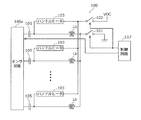
- ten handle heaters 103 are arranged so as to cover almost the entire circumference.
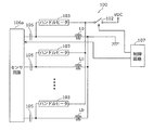
- FIG. 11A is a block diagram illustrating a configuration example of the handle heater device 100 according to the second embodiment.
- the configuration example in the figure corresponds to the plurality of handle heaters 103 shown in FIG.
- the handle heater device 100 shown in the figure has a plurality of sets each including a handle heater 103, an inductor La, an inductor Lb, and a coupling capacitor 105, and further includes a switch 101, a sensor circuit 106a, and a control circuit 107 that are shared by each set. .
- the number of sets is 10 when corresponding to FIG.
- the sensor circuit 106a may be configured to include the same number of sensor circuits 106 shown in FIG. 4 as the number of sets. Alternatively, the sensor circuit 106a may be configured to include at least one sensor circuit 106 illustrated in FIG. For example, when the sensor circuit 106a is configured to include the same number of sensor circuits 106 as the number of sets, the control circuit 107 performs control to sequentially enable each of the sensor circuits 106 in a time division manner during the ON period illustrated in FIG. do.
- the enabling may be a control for bringing the sensor circuit 106 from the stopped state to the operating state, or a control for fetching only the determination result of one sensor circuit while the plurality of sensor circuits 106 are in the operating state, that is, 1 It may be a control to obtain a determination result without masking only one sensor circuit.
- the control circuit 107 operates the sensor circuit 106a while switching the plurality of handle heaters 103 in a time division manner within the range of the time chart of FIG. Alternatively, the control circuit 107 may enable the sensor circuit 106a to determine whether or not there is contact with at least two of the plurality of handle heaters 103 at the same time.
- the plurality of handle heaters 103 are provided, it is possible to detect in detail where the steering handle is gripped. Further, it is possible to detect in detail the position where a human hand is close to the steering handle.
- the steering handle is held by both hands, only the right hand, or only the left hand, and where the position is. Further, by recording the gripping position together with the movement of the steering wheel as a history, it becomes possible to analyze the habits and tendencies of the operator during normal times and accidents.
- the history recording may be linked with the drive recorder.
- information related to gripping the steering wheel can be transmitted to the outside of the vehicle or the like on which the handle heater device 100 is mounted, and the information can be used by a device outside the vehicle or the like.
- FIG. 11B is a block diagram illustrating a first modification of the handle heater device according to the second exemplary embodiment.
- the handle heater device 100 shown in FIG. 11B is different from FIG. 11A in that a plurality of inductors La are deleted.
- the handle heater 103 has an inductance component, the inductor La does not have to be provided as shown in FIG. 11A.
- This first modification is suitable for the first configuration example of the handle heater having an inductance component, that is, the handle heater 103 shown in FIG.
- FIG. 11C is a block diagram illustrating a second modification of the handle heater device according to the second embodiment.
- the handle heater device 100 shown in FIG. 11C is different from that shown in FIG. 11B in that the switch 101 is deleted and a switch 102 connected in series to the second terminals of the plurality of handle heaters 103 is added.
- the second modification is also suitable for the first configuration example of the handle heater 103 shown in FIG.
- FIG. 11D is a block diagram illustrating a third modification of the handle heater device according to the second embodiment.
- the handle heater device 100 shown in FIG. 11D is different from FIG. 11B in that a switch 102 connected in series to the second terminals of the plurality of handle heaters 103 is added.
- Another example of the third modification is also suitable for the first configuration example of the handle heater 103 shown in FIG.
- the handle heater device 100 may include at least one switch. That is, at least one switch is connected to the first terminal of each of the plurality of handle heaters 103 to each of the switch 101 connected to each of the plurality of inductors Lb and each of the second terminals of the plurality of handle heaters 103. It may be at least one of the switched switches 102.
- the plurality of second terminals may be connected to a switch or a power line without interposing an inductor element. Further, the connection between the power source VDC and the ground may be reversed. Also in FIG. 11A, the connection between the power supply VDC and the ground may be reversed.
- all or part of the sensor circuits 106 and 106a may be constituted by a microcomputer or a one-chip LSI.
- the sensor circuits 106 and 106 a are connected to the first terminal of the handle heater 103 via the coupling capacitor 105, a configuration including a diode instead of the coupling capacitor 105 may be used.
- the anode of the diode is connected to the sensor circuit 106, and the cathode is connected to the first terminal.
- the coupling capacitor 105 may be deleted and the sensor circuit 106 may be directly connected.
- the handle heater device 100 according to one or a plurality of aspects has been described based on the embodiment, but the present invention is not limited to this embodiment. Unless it deviates from the gist of the present invention, various modifications conceived by those skilled in the art have been made in this embodiment, and forms constructed by combining components in different embodiments are also within the scope of one or more aspects. May be included.
- the power source VDC supplies direct-current electric energy.
- this “direct current” is not only a direct current in a narrow sense in which the voltage or current does not change, but also ripple, pulsating current, and the like. It is a concept that indicates a direct current in a broad sense including a minute change in electrical energy.
- the electric energy supplied to the handle heater 103 is described as DC.
- AC electric energy that changes in a long cycle that is, the frequency is low
- the handle heater 103 can be driven because it passes through the inductors La and Lb.
- the long period here is a period that is considerably longer than the period of the AC signal output from the sensor circuit 106, for example, a period that is three digits or more longer.
- determining whether or not the handle heater 103 is in contact with the human hand is described. However, if the capacitance of the handle heater 103 is changed, the presence or absence of contact is determined. The determination is possible, and the detection target as a determination target is not limited to a human hand.
- the present invention can be used as a handle heater device or the like that determines whether or not a detected object such as a human hand is in contact with a steering handle of a vehicle or the like.
Landscapes
- Engineering & Computer Science (AREA)
- Transportation (AREA)
- Mechanical Engineering (AREA)
- Power Engineering (AREA)
- Chemical & Material Sciences (AREA)
- Combustion & Propulsion (AREA)
- Physics & Mathematics (AREA)
- Electromagnetism (AREA)
- Steering Controls (AREA)
- Surface Heating Bodies (AREA)
Abstract
Description
このような課題を解決するために、本発明の一態様に係るハンドルヒータ装置は、操舵ハンドルに備えられ、電気エネルギにより発熱する電気抵抗体で構成されたハンドルヒータと、第1のインダクタと、少なくとも1つのスイッチと、センサ回路とを有する。第1のインダクタはハンドルヒータの第1端子に直列に接続されている。少なくとも1つのスイッチはハンドルヒータへの電力供給をオンまたはオフする。センサ回路は第1端子に電気的に接続され、ハンドルヒータの静電容量の大きさに基づいてハンドルヒータと被検出体との接触の有無を判定する。少なくとも1つのスイッチは、ハンドルヒータの第1端子に第1のインダクタを介して直列接続された第1のスイッチ、および、ハンドルヒータの第2端子に直列接続された第2のスイッチの少なくとも一方である。
図1は、実施の形態1における手の接触検知を兼ねるハンドルヒータを備える操舵ハンドルの例を示す図である。
図10は、実施の形態2における手の接触検知を兼ねるハンドルヒータを備える操舵ハンドルの例を示す図である。同図の操舵ハンドルは、複数のハンドルヒータ103をそれぞれ異なる位置に備える。複数のハンドルヒータ103は、操舵ハンドルの全周をカバーするように配置してもよいし、人が把持する主要な部分をカバーするように配置しても良い。同図では、ほぼ全周をカバーするように10個のハンドルヒータ103が配置されている。
101,102 スイッチ
103 ハンドルヒータ
105 結合容量
106,106a センサ回路
107 制御回路
111 支持体
111a 接続部材
110 電熱線
112 面状電気抵抗体
130 電荷注入部
131 パルス発生器
132,133 スイッチ
140 平滑回路
150 AD変換器
160 判定部
La,Lb インダクタ
Claims (13)
- 操舵ハンドルに備えられ、電気エネルギにより発熱する電気抵抗体で構成され、第1端子と第2端子とを有するハンドルヒータと、
前記ハンドルヒータの第1端子に直列に接続された第1のインダクタと、
前記ハンドルヒータへの電力供給をオンまたはオフする少なくとも1つのスイッチと、
前記第1端子に電気的に接続され、前記ハンドルヒータの静電容量の大きさに基づいて前記ハンドルヒータと被検出体との接触の有無を判定するセンサ回路と、を備え、
前記少なくとも1つのスイッチは、前記ハンドルヒータの前記第1端子に前記第1のインダクタを介して直列接続された第1のスイッチ、および、前記ハンドルヒータの前記第2端子に直列接続された第2のスイッチの少なくとも一方である、
ハンドルヒータ装置。 - 前記第2端子は、インダクタ素子を介在することなく、前記スイッチまたは電源線に接続される、
請求項1に記載のハンドルヒータ装置。 - 前記ハンドルヒータへの電力供給がオンの状態およびオフの状態に同期した有効期間であって、前記センサ回路により前記ハンドルヒータと被検出体との接触の有無を判定する有効期間を決定し、前記有効期間以外の期間では前記センサ回路を無効化する制御部をさらに備えた、
請求項1または2に記載のハンドルヒータ装置。 - 前記制御部は、前記ハンドルヒータへの電力供給がオンの状態である期間の範囲内の期間を、前記有効期間の1つとする、
請求項3に記載のハンドルヒータ装置。 - 前記制御部は、前記ハンドルヒータへの電力供給がオフ状態から安定的なオン状態に切り替わるまでの過渡期間と、オン状態から安定的なオフ状態に切り替わるまでの過渡期間とを除いて前記有効期間とする、
請求項3に記載のハンドルヒータ装置。 - 前記ハンドルヒータは、前記第1端子と前記第2端子間に接続されるとともに、複数回折り返し配線された電熱線を含む、
請求項1から5のいずれか1項に記載のハンドルヒータ装置。 - 前記ハンドルヒータは、前記第1端子と前記第2端子間に接続された面状電気抵抗体を含む、
請求項1から5のいずれか1項に記載のハンドルヒータ装置。 - 前記センサ回路は、前記ハンドルヒータに前記第1端子を介して交流信号を出力し、かつ、前記ハンドルヒータから前記第1端子を介して入力される信号のレベルを検出することによって、前記操舵ハンドルと前記被検出体との接触の有無を判定する、
請求項1から7のいずれか1項に記載のハンドルヒータ装置。 - 前記操舵ハンドルに備えられ、前記ハンドルヒータを含む複数のハンドルヒータと、
前記複数のハンドルヒータの第1端子のそれぞれに直列接続された、前記第1のインダクタを含む複数の第1のインダクタと、を備え、
前記少なくとも1つのスイッチは、前記複数のハンドルヒータそれぞれの前記第1端子に、前記複数の第1のインダクタのそれぞれを介して接続された第1のスイッチ、および、前記複数のハンドルヒータの第2端子のそれぞれに接続された第2のスイッチの少なくとも一方であり、
前記複数のハンドルヒータの前記第1端子のそれぞれには、前記センサ回路が電気的に接続される、
請求項1に記載のハンドルヒータ装置。 - 前記複数のハンドルヒータへの電力供給がオンの状態およびオフの状態に同期した有効期間であって、前記センサ回路により前記複数のハンドルヒータと被検出体との接触の有無を判定する有効期間を決定し、前記有効期間以外の期間では前記センサ回路を無効化する制御部をさらに備え、
前記制御部は、前記複数のハンドルヒータを時分割で切り替えながら前記センサ回路を有効化する、
請求項9に記載のハンドルヒータ装置。 - 前記複数のハンドルヒータへの電力供給がオンの状態およびオフの状態に同期した有効期間であって、前記センサ回路により前記複数のハンドルヒータと被検出体との接触の有無を判定する有効期間を決定し、前記有効期間以外の期間では前記センサ回路を無効化する制御部をさらに備え、
前記制御部は、前記複数のハンドルヒータのうち少なくとも2つに対して同時に前記接触の有無を判定するよう前記センサ回路を有効化する、
請求項9に記載のハンドルヒータ装置。 - 前記センサ回路は、前記複数のハンドルヒータのそれぞれに前記第1端子を介して交流信号を出力し、かつ、前記複数のハンドルヒータのそれぞれから前記第1端子を介して入力される信号のレベルを検出することによって、前記操舵ハンドルと前記被検出体との接触の有無を判定する、
請求項9から11のいずれか1項に記載のハンドルヒータ装置。 - 前記電気エネルギは、直流の電気エネルギである、
請求項1から12のいずれか1項に記載のハンドルヒータ装置。
Priority Applications (3)
| Application Number | Priority Date | Filing Date | Title |
|---|---|---|---|
| US14/890,148 US10449989B2 (en) | 2013-12-12 | 2014-12-04 | Steering wheel heater device |
| CN201480010578.3A CN105103649B (zh) | 2013-12-12 | 2014-12-04 | 方向盘加热器装置 |
| EP14864976.7A EP3082377B1 (en) | 2013-12-12 | 2014-12-04 | Steering-wheel heater device |
Applications Claiming Priority (4)
| Application Number | Priority Date | Filing Date | Title |
|---|---|---|---|
| JP2013-257403 | 2013-12-12 | ||
| JP2013257403 | 2013-12-12 | ||
| JP2014-150228 | 2014-07-23 | ||
| JP2014150228A JP5842104B2 (ja) | 2013-12-12 | 2014-07-23 | ハンドルヒータ装置 |
Publications (1)
| Publication Number | Publication Date |
|---|---|
| WO2015087520A1 true WO2015087520A1 (ja) | 2015-06-18 |
Family
ID=53370849
Family Applications (1)
| Application Number | Title | Priority Date | Filing Date |
|---|---|---|---|
| PCT/JP2014/006067 Ceased WO2015087520A1 (ja) | 2013-12-12 | 2014-12-04 | ハンドルヒータ装置 |
Country Status (5)
| Country | Link |
|---|---|
| US (1) | US10449989B2 (ja) |
| EP (1) | EP3082377B1 (ja) |
| JP (1) | JP5842104B2 (ja) |
| CN (1) | CN105103649B (ja) |
| WO (1) | WO2015087520A1 (ja) |
Cited By (1)
| Publication number | Priority date | Publication date | Assignee | Title |
|---|---|---|---|---|
| US10302794B2 (en) | 2016-10-17 | 2019-05-28 | Joyson Safety Systems Japan K. K. | Detection system for detecting a person on a seat |
Families Citing this family (30)
| Publication number | Priority date | Publication date | Assignee | Title |
|---|---|---|---|---|
| US10252741B2 (en) * | 2014-07-17 | 2019-04-09 | Panasonic Corporation | Electrostatic steering wheel hold detection device |
| DE102014117820A1 (de) | 2014-12-04 | 2016-06-09 | Valeo Schalter Und Sensoren Gmbh | Sensorsystem für ein Lenkrad eines Kraftfahrzeugs, Lenkrad mit einem solchen Sensorsystem und Verfahren zum Betrieb eines solchen Sensorsystems |
| US10946722B2 (en) * | 2015-08-27 | 2021-03-16 | Denso Corporation | Heater device |
| US10396584B2 (en) * | 2016-04-25 | 2019-08-27 | Visteon Global Technologies, Inc. | Wireless charging steering wheel |
| CN110891822B (zh) * | 2017-05-15 | 2023-01-06 | 乔伊森安全系统收购有限责任公司 | 加热车辆部件并感测与车辆部件的接近度的系统和方法 |
| US10947945B2 (en) * | 2017-10-20 | 2021-03-16 | Lee J. Santoro | Methods and systems for control of electric components |
| CN107911877B (zh) * | 2017-10-31 | 2020-07-28 | 安徽江淮汽车集团股份有限公司 | 方向盘加热控制系统及方法 |
| KR102019568B1 (ko) | 2017-12-19 | 2019-11-04 | 현대자동차주식회사 | 자율주행차량의 스티어링 휠 파지 감지 시스템 및 방법 |
| JP6596743B2 (ja) * | 2017-12-28 | 2019-10-30 | 本田技研工業株式会社 | 車両用ステアリング装置 |
| WO2019147800A2 (en) | 2018-01-24 | 2019-08-01 | Gentherm Inc. | Capacitive sensing and heating system for steering wheels or seats to sense presence of hand of occupant on steering wheel or occupant in seat |
| EP3575182B1 (de) * | 2018-05-31 | 2021-04-07 | Volkswagen AG | Beheizbarer berührungssensor und lenkrad aufweisend einen derartigen berührungssensor |
| CN112135766B (zh) * | 2018-06-06 | 2022-12-02 | 奥托立夫开发公司 | 方向盘、方向盘系统、控制方向盘的方法以及非临时计算机可读存储介质 |
| LU100985B1 (en) * | 2018-11-13 | 2020-05-13 | Iee Sa | System for Capacitive Object Detection |
| JP7155921B2 (ja) * | 2018-11-16 | 2022-10-19 | 株式会社アイシン | ステアリング装置 |
| CN111688546B (zh) * | 2019-03-13 | 2024-12-13 | 袁环珍 | 一种加热装置 |
| DE102019124294B4 (de) * | 2019-09-10 | 2022-05-25 | Valeo Schalter Und Sensoren Gmbh | Kombinierte, kapazitive Sensor- und Heizvorrichtung, Verfahren zum Betrieb einer Sensor- und Heizvorrichtung, Lenkradbaugruppe mit einer Sensor- und Heizvorrichtung und Fahrzeug mit einer Lenkradbaugruppe |
| DE102019128887A1 (de) * | 2019-10-25 | 2021-04-29 | Valeo Schalter Und Sensoren Gmbh | Kombinierte, kapazitive Sensor- und Heizvorrichtung, Verfahren zum Betrieb einer Sensor- und Heizvorrichtung, Lenkeingabevorrichtungs-Baugruppe mit einer Sensor- und Heizvorrichtung und Fahrzeug mit einer Lenkeingabevorrichtungs-Baugruppe |
| DE102019218348A1 (de) * | 2019-11-27 | 2021-05-27 | Eberspächer Catem Gmbh & Co. Kg | Elektrische heizvorrichtung für ein kraftfahrzeug |
| JP2021154850A (ja) * | 2020-03-26 | 2021-10-07 | 豊田合成株式会社 | ステアリングホイール |
| GB2596586B (en) * | 2020-07-03 | 2023-11-29 | Jaguar Land Rover Ltd | Control of functions of a vehicle steering wheel |
| US11505233B2 (en) | 2020-08-25 | 2022-11-22 | Ford Global Technologies, Llc | Heated vehicle steering wheel having multiple controlled heating zones |
| US11485399B2 (en) | 2020-09-10 | 2022-11-01 | Ford Global Technologies, Llc | Heated vehicle steering wheel having multiple heaters with integrated sensors |
| LU500033B1 (en) | 2021-04-12 | 2022-10-12 | Iee Sa | Low-Cost, Protected Capacitive Sensing Circuit for Loading Mode Operation of Capacitive Sensors Employing Heater Members |
| CN114523981A (zh) * | 2022-03-17 | 2022-05-24 | 上海科世达-华阳汽车电器有限公司 | 一种方向盘脱手检测电路和系统 |
| JP2024093933A (ja) * | 2022-12-27 | 2024-07-09 | パナソニックオートモーティブシステムズ株式会社 | 輻射ヒータおよび輻射ヒータ装置 |
| CN116552621B (zh) * | 2023-06-20 | 2025-09-09 | 中国第一汽车股份有限公司 | 车辆的方向盘的加热方法、装置、处理器和电子设备 |
| DE102023209657A1 (de) * | 2023-09-29 | 2025-04-03 | Benecke-Kaliko Aktiengesellschaft | System und Verfahren zur Regelung der Temperatur einer mehrschichtigen Verbundstruktur |
| CN120229100A (zh) * | 2023-12-28 | 2025-07-01 | 松下汽车电子系统株式会社 | 显示装置和显示方法 |
| WO2025238777A1 (ja) * | 2024-05-15 | 2025-11-20 | 日産自動車株式会社 | ステアリングのヒータの制御装置及び制御方法 |
| DE102024126310A1 (de) * | 2024-09-12 | 2026-03-12 | Marquardt Gmbh | Vorrichtung zur Beheizung und fehlersicheren Erkennung einer Berührung einer Fläche |
Citations (7)
| Publication number | Priority date | Publication date | Assignee | Title |
|---|---|---|---|---|
| JP2002340712A (ja) | 2001-05-04 | 2002-11-27 | Robert Bosch Gmbh | 手と操舵ハンドルとの間の接触の検出方法および装置 |
| JP2003535341A (ja) * | 2000-05-26 | 2003-11-25 | オートモーティブ システムズ ラボラトリー インコーポレーテッド | 乗員センサ |
| JP2005297704A (ja) * | 2004-04-09 | 2005-10-27 | Matsushita Electric Ind Co Ltd | ステアリングホイール |
| JP2007284033A (ja) * | 2006-03-24 | 2007-11-01 | Matsushita Electric Ind Co Ltd | ステアリングホイール用面状発熱体 |
| JP2008024087A (ja) | 2006-07-19 | 2008-02-07 | Denso Corp | 車両用座席装置及びその製造方法 |
| US20110121618A1 (en) * | 2009-11-20 | 2011-05-26 | Delphi Technologies, Inc. | Seat occupant detection circuit isolation from seat heating circuit using a common mode choke |
| US20130098890A1 (en) * | 2011-09-21 | 2013-04-25 | Iee International Electronics & Engineering S.A. | Capacitive sensing system configured for using heating element as antenna electrode |
Family Cites Families (4)
| Publication number | Priority date | Publication date | Assignee | Title |
|---|---|---|---|---|
| WO2001064496A2 (en) * | 2000-02-28 | 2001-09-07 | Delphi Technologies, Inc. | Apparatus and method for heating a steering wheel |
| JP2010023699A (ja) * | 2008-07-22 | 2010-02-04 | Tokai Rika Co Ltd | タッチ操作判定装置 |
| US8138772B2 (en) * | 2008-08-15 | 2012-03-20 | Tk Holdings Inc. | Capacitive sensing and method |
| DE102011005551B4 (de) * | 2011-03-15 | 2012-12-27 | TAKATA Aktiengesellschaft | Belegungserkennungsvorrichtung zum Erkennen einer Belegung eines Sitzplatzes eines Kraftfahrzeuges |
-
2014
- 2014-07-23 JP JP2014150228A patent/JP5842104B2/ja not_active Expired - Fee Related
- 2014-12-04 CN CN201480010578.3A patent/CN105103649B/zh active Active
- 2014-12-04 WO PCT/JP2014/006067 patent/WO2015087520A1/ja not_active Ceased
- 2014-12-04 US US14/890,148 patent/US10449989B2/en active Active
- 2014-12-04 EP EP14864976.7A patent/EP3082377B1/en active Active
Patent Citations (7)
| Publication number | Priority date | Publication date | Assignee | Title |
|---|---|---|---|---|
| JP2003535341A (ja) * | 2000-05-26 | 2003-11-25 | オートモーティブ システムズ ラボラトリー インコーポレーテッド | 乗員センサ |
| JP2002340712A (ja) | 2001-05-04 | 2002-11-27 | Robert Bosch Gmbh | 手と操舵ハンドルとの間の接触の検出方法および装置 |
| JP2005297704A (ja) * | 2004-04-09 | 2005-10-27 | Matsushita Electric Ind Co Ltd | ステアリングホイール |
| JP2007284033A (ja) * | 2006-03-24 | 2007-11-01 | Matsushita Electric Ind Co Ltd | ステアリングホイール用面状発熱体 |
| JP2008024087A (ja) | 2006-07-19 | 2008-02-07 | Denso Corp | 車両用座席装置及びその製造方法 |
| US20110121618A1 (en) * | 2009-11-20 | 2011-05-26 | Delphi Technologies, Inc. | Seat occupant detection circuit isolation from seat heating circuit using a common mode choke |
| US20130098890A1 (en) * | 2011-09-21 | 2013-04-25 | Iee International Electronics & Engineering S.A. | Capacitive sensing system configured for using heating element as antenna electrode |
Cited By (1)
| Publication number | Priority date | Publication date | Assignee | Title |
|---|---|---|---|---|
| US10302794B2 (en) | 2016-10-17 | 2019-05-28 | Joyson Safety Systems Japan K. K. | Detection system for detecting a person on a seat |
Also Published As
| Publication number | Publication date |
|---|---|
| JP5842104B2 (ja) | 2016-01-13 |
| US10449989B2 (en) | 2019-10-22 |
| EP3082377B1 (en) | 2019-07-31 |
| US20160101805A1 (en) | 2016-04-14 |
| EP3082377A4 (en) | 2016-12-21 |
| CN105103649A (zh) | 2015-11-25 |
| CN105103649B (zh) | 2016-10-12 |
| JP2015131631A (ja) | 2015-07-23 |
| EP3082377A1 (en) | 2016-10-19 |
Similar Documents
| Publication | Publication Date | Title |
|---|---|---|
| JP5842104B2 (ja) | ハンドルヒータ装置 | |
| JP6327528B2 (ja) | ハンドルヒータ装置 | |
| US10308273B2 (en) | Steering wheel heater and steering wheel | |
| JP6398091B2 (ja) | 静電式把持検出装置 | |
| JP6280649B2 (ja) | 静電式ステアリングホイール把持検出装置 | |
| KR102526134B1 (ko) | 스티어링, 스티어링 시스템, 스티어링을 제어하는 방법 및 비일시적인 컴퓨터 판독가능 기억 매체 | |
| JP4721060B2 (ja) | 車両用座席装置 | |
| RU2020133207A (ru) | Индукционное нагревательное устройство | |
| JP6503913B2 (ja) | 車両用ドアハンドル駆動装置及び車両用通信装置 | |
| JP2011083132A5 (ja) | 電力供給システム、及びそのための可動体と固定体 | |
| JP2010023699A (ja) | タッチ操作判定装置 | |
| KR102406101B1 (ko) | 구성 요소 및 구성 요소의 점유 접촉을 식별하기 위한 방법 | |
| JP4311178B2 (ja) | 誘導加熱装置 | |
| JP2017187893A (ja) | 操作検出装置 | |
| US20130327758A1 (en) | Operating or adjusting device having user-specific switching and/or adjusting functionality | |
| JP2025132536A (ja) | ステアリングホイール把持検出装置 | |
| LU100985B1 (en) | System for Capacitive Object Detection | |
| CN108351372B9 (zh) | 用于检测测量传感器的测量电阻的电阻值的设备 | |
| JP4165186B2 (ja) | 面状採暖具 | |
| JP4904902B2 (ja) | 誘導加熱装置 | |
| JP2018051099A (ja) | 生体の皮膚抵抗検出装置 | |
| CN121666338A (zh) | 用于手离检测的电容感测装置 | |
| JP2015125500A (ja) | 有線接続された座標指示ペンを使用した静電容量結合型座標検出装置 | |
| JPH0272579A (ja) | 電気暖房器具の発熱体制御装置 |
Legal Events
| Date | Code | Title | Description |
|---|---|---|---|
| WWE | Wipo information: entry into national phase |
Ref document number: 201480010578.3 Country of ref document: CN |
|
| REEP | Request for entry into the european phase |
Ref document number: 2014864976 Country of ref document: EP |
|
| WWE | Wipo information: entry into national phase |
Ref document number: 2014864976 Country of ref document: EP |
|
| 121 | Ep: the epo has been informed by wipo that ep was designated in this application |
Ref document number: 14864976 Country of ref document: EP Kind code of ref document: A1 |
|
| WWE | Wipo information: entry into national phase |
Ref document number: 14890148 Country of ref document: US |
|
| NENP | Non-entry into the national phase |
Ref country code: DE |