WO2015087653A1 - 光学検査装置 - Google Patents
光学検査装置 Download PDFInfo
- Publication number
- WO2015087653A1 WO2015087653A1 PCT/JP2014/079865 JP2014079865W WO2015087653A1 WO 2015087653 A1 WO2015087653 A1 WO 2015087653A1 JP 2014079865 W JP2014079865 W JP 2014079865W WO 2015087653 A1 WO2015087653 A1 WO 2015087653A1
- Authority
- WO
- WIPO (PCT)
- Prior art keywords
- light
- unit
- optical inspection
- light detection
- detection unit
- Prior art date
- Legal status (The legal status is an assumption and is not a legal conclusion. Google has not performed a legal analysis and makes no representation as to the accuracy of the status listed.)
- Ceased
Links
Images



Classifications
-
- G—PHYSICS
- G01—MEASURING; TESTING
- G01N—INVESTIGATING OR ANALYSING MATERIALS BY DETERMINING THEIR CHEMICAL OR PHYSICAL PROPERTIES
- G01N21/00—Investigating or analysing materials by the use of optical means, i.e. using sub-millimetre waves, infrared, visible or ultraviolet light
- G01N21/84—Systems specially adapted for particular applications
- G01N21/88—Investigating the presence of flaws or contamination
- G01N21/8806—Specially adapted optical and illumination features
-
- G—PHYSICS
- G01—MEASURING; TESTING
- G01N—INVESTIGATING OR ANALYSING MATERIALS BY DETERMINING THEIR CHEMICAL OR PHYSICAL PROPERTIES
- G01N21/00—Investigating or analysing materials by the use of optical means, i.e. using sub-millimetre waves, infrared, visible or ultraviolet light
- G01N21/17—Systems in which incident light is modified in accordance with the properties of the material investigated
- G01N21/59—Transmissivity
-
- G—PHYSICS
- G01—MEASURING; TESTING
- G01N—INVESTIGATING OR ANALYSING MATERIALS BY DETERMINING THEIR CHEMICAL OR PHYSICAL PROPERTIES
- G01N21/00—Investigating or analysing materials by the use of optical means, i.e. using sub-millimetre waves, infrared, visible or ultraviolet light
- G01N21/84—Systems specially adapted for particular applications
- G01N21/88—Investigating the presence of flaws or contamination
- G01N21/90—Investigating the presence of flaws or contamination in a container or its contents
-
- G—PHYSICS
- G01—MEASURING; TESTING
- G01N—INVESTIGATING OR ANALYSING MATERIALS BY DETERMINING THEIR CHEMICAL OR PHYSICAL PROPERTIES
- G01N21/00—Investigating or analysing materials by the use of optical means, i.e. using sub-millimetre waves, infrared, visible or ultraviolet light
- G01N21/84—Systems specially adapted for particular applications
- G01N21/88—Investigating the presence of flaws or contamination
- G01N21/94—Investigating contamination, e.g. dust
-
- G—PHYSICS
- G01—MEASURING; TESTING
- G01N—INVESTIGATING OR ANALYSING MATERIALS BY DETERMINING THEIR CHEMICAL OR PHYSICAL PROPERTIES
- G01N21/00—Investigating or analysing materials by the use of optical means, i.e. using sub-millimetre waves, infrared, visible or ultraviolet light
- G01N21/84—Systems specially adapted for particular applications
- G01N21/88—Investigating the presence of flaws or contamination
- G01N21/95—Investigating the presence of flaws or contamination characterised by the material or shape of the object to be examined
-
- G—PHYSICS
- G01—MEASURING; TESTING
- G01N—INVESTIGATING OR ANALYSING MATERIALS BY DETERMINING THEIR CHEMICAL OR PHYSICAL PROPERTIES
- G01N21/00—Investigating or analysing materials by the use of optical means, i.e. using sub-millimetre waves, infrared, visible or ultraviolet light
- G01N21/84—Systems specially adapted for particular applications
- G01N2021/845—Objects on a conveyor
-
- G—PHYSICS
- G01—MEASURING; TESTING
- G01N—INVESTIGATING OR ANALYSING MATERIALS BY DETERMINING THEIR CHEMICAL OR PHYSICAL PROPERTIES
- G01N21/00—Investigating or analysing materials by the use of optical means, i.e. using sub-millimetre waves, infrared, visible or ultraviolet light
- G01N21/84—Systems specially adapted for particular applications
- G01N21/88—Investigating the presence of flaws or contamination
- G01N21/89—Investigating the presence of flaws or contamination in moving material, e.g. running paper or textiles
- G01N21/8901—Optical details; Scanning details
-
- G—PHYSICS
- G01—MEASURING; TESTING
- G01N—INVESTIGATING OR ANALYSING MATERIALS BY DETERMINING THEIR CHEMICAL OR PHYSICAL PROPERTIES
- G01N2201/00—Features of devices classified in G01N21/00
- G01N2201/06—Illumination; Optics
- G01N2201/062—LED's
Definitions
- the present invention relates to an optical inspection apparatus.
- Patent Document 1 discloses a gap between an upstream conveyance section and a downstream conveyance section that convey an article, and an upstream conveyance section and a downstream conveyance section.
- An optical inspection device is described that includes an illumination unit that irradiates an article with light from above and an imaging unit that images the article from below the gap.
- Patent Document 1 when the optical inspection apparatus described in Patent Document 1 is installed in an existing conveyance line that conveys articles, it is necessary to provide a space corresponding to the upstream conveyance unit and the downstream conveyance unit in the existing conveyance line.
- the layout has to be changed, and the work is complicated.
- an object of the present invention is to provide an optical inspection apparatus that can be easily installed on an existing conveyance line for conveying an article.
- An optical inspection apparatus includes a light irradiation unit that irradiates an article with light, a light detection unit that detects transmitted light of light irradiated on the article, and a cantilever of the light irradiation unit and the light detection unit. And an inspection region of the article by light is exposed to the ambient atmosphere.
- one side of the conveyance line is arranged so that the light irradiation unit and the light detection unit are opposed to the existing conveyance line that conveys the article with a gap between successive conveyance conveyors interposed therebetween. Therefore, the optical inspection device can be easily installed. Examples of light to be irradiated include visible light, ultraviolet light, near infrared light, and infrared light.
- the light detection unit may be disposed above the light irradiation unit. According to this configuration, it is possible to suppress the adhesion of dust to the light detection unit, which is likely to deteriorate the detection accuracy as compared with the case where dust adheres to the light irradiation unit. Furthermore, it is possible to suppress light such as illumination around the optical inspection apparatus from entering the light detection unit as disturbance light.
- the light irradiation unit and the light detection unit may be movable up and down integrally with the support unit. According to this structure, the position of the light irradiation part with respect to the existing conveyance line and the light detection part can be adjusted easily.
- the position of the light detection unit may be adjustable with respect to the light irradiation unit. According to this configuration, the position of the light detection unit can be adjusted with high accuracy.
- the light irradiation unit and the light detection unit may be rotatable integrally with the support unit. According to this configuration, for example, when the transport surface of a continuous transport conveyor is inclined in an existing transport line, the light irradiation unit and the light detection unit are opposed to each other in a direction perpendicular to the transport surface. In addition, the angles of the light irradiation unit and the light detection unit with respect to the existing conveyance line can be easily adjusted.
- the light irradiation unit and the light detection unit can rotate integrally with the support unit around a position where the distance from the light irradiation unit is smaller than the distance from the light detection unit. It may be. According to this configuration, since the rotation amount of the light irradiation unit is smaller than the rotation amount of the light detection unit, the light irradiation unit is disposed in the vicinity of the gap between the continuous conveyors to attenuate the light irradiated to the article. It is possible to suppress a decrease in detection sensitivity due to the light detection unit.
- the support portion includes a support column portion, one end portion fixed to the support column portion, a first beam portion supporting the light irradiation unit, and one end portion fixed to the support column portion. And a second beam portion that supports the detection unit.
- the support unit is prevented from interfering with the existing conveyance line, and the light is suppressed.
- the irradiation unit and the light detection unit can be arranged at desired positions.
- the light may be near infrared rays.
- near-infrared rays having a higher transmission power than visible light the state of the article can be inspected with high accuracy.
- An optical inspection apparatus acquires a light transmission image of an article in which contents are contained in a package from a light detection unit, and seals based on a pre-stored positional relationship of the sealing unit of the package. You may further provide the control part which sets the test
- an optical inspection apparatus that can be easily installed on an existing conveyance line for conveying an article.
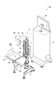
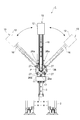
- FIG. 1 It is a perspective view of an optical inspection system provided with the optical inspection apparatus of one embodiment of the present invention. It is a perspective view of the optical inspection apparatus of FIG. It is a right view of the optical inspection apparatus of FIG. It is a right view of the optical inspection apparatus of FIG. It is a front view of the optical inspection apparatus of FIG. It is a top view of the articles
- the optical inspection apparatus 1 is an apparatus that is retrofitted to a portion of the existing conveyance line 100 that conveys an article 50 where a gap 103 between successive conveyors 101 and 102 exists. is there.
- the optical inspection apparatus 1 targets, for example, an article 50 having a package such as a film wrapping material and a content such as food contained in the package.
- a control device 30 is electrically connected to the optical inspection device 1 by wire or wirelessly, and the optical inspection device 1 and the control device 30 constitute an optical inspection system.
- the control device 30 includes a control box 31 that accommodates a computer, and an operation panel 32.
- the control device 30 controls the operation of the optical inspection device 1 and, on the basis of the detection signal output from the optical inspection device 1, a defect of the article 50 (for example, biting of the contents into the sealing portion of the package, The contents of the package are damaged, foreign matter is mixed in the package, etc., and the contents (mass, quantity, etc.) of the contents in the package are estimated.
- the optical inspection apparatus 1 includes a leg 2 installed on the floor surface and a quadrangular columnar main pillar 3 standing on the leg 2.
- a guide rail 4 extending in the vertical direction is provided on the front surface 3a of the main pillar 3 (the surface on the transport line 100 side).
- a belt 6 is stretched over the right side surface 3 c (right side surface when viewed from the conveyance line 100 side) and the left side surface 3 d of the main column 3 via the upper end portion of the main column 3.
- the inspection head 10 is attached to the guide rail 4 so as to be movable along the guide rail 4.
- One end of the belt 6 located on the right side surface 3 c of the main pillar 3 is fixed to the inspection head 10.
- a weight 7 is attached to the guide rail 5 so as to be movable along the guide rail 5.
- the other end portion of the belt 6 positioned on the left side surface 3d of the main pillar 3 is fixed to the weight 7.
- the weight 7 is lowered along the guide rail 5.
- the weight 7 is raised along the guide rail 5.
- the inspection head 10 is fixed to the main pillar 3 by the lever 8 after being arranged at a desired height.
- the vertical movement of the inspection head 10 relative to the main pillar 3 is facilitated by using the weight 7.
- the inspection head 10 includes a light irradiation unit 11 that irradiates the article 50 with light, a light detection unit 12 that detects transmitted light of the light irradiated on the article 50, the light irradiation unit 11, and And a support unit 13 that supports the light detection unit 12 in a cantilever manner.
- the light irradiation unit 11 is disposed below the gap 103 between the continuous conveyors 101 and 102, and the light detection unit 12 is disposed above the gap 103.
- the light path from the light irradiation unit 11 to the light detection unit 12 is exposed to the surrounding atmosphere. That is, the inspection area of the article 50 by light is not covered with a shield box or the like and is exposed to the surrounding atmosphere.
- a cover may be provided so as to cover at least a part of the inspection region in order to block disturbance light.
- the light irradiation unit 11 includes a plurality of LEDs arranged in the horizontal direction (the direction in which the gap 103 extends).
- the light irradiation unit 11 irradiates the article 50 with near infrared rays through the gap 103 when the article 50 passes over the gap 103 between the continuous conveyors 101 and 102.
- the wavelength of near infrared rays is 780 nm to 1100 nm.
- the light detection unit 12 is a line sensor and includes a plurality of PDs arranged in the horizontal direction (the direction in which the gap 103 extends).
- the light detection unit 12 detects near-infrared transmitted light irradiated on the article 50 when the article 50 passes through the gap 103 between the continuous conveyors 101 and 102, and outputs a detection signal to the control device 30. .
- the support unit 13 includes a column unit 16 including a first column unit 14 and a second column unit 15, a first beam unit 17, and a second beam unit 18.
- the first support column portion 14 is provided with a guide groove 14a extending in the vertical direction.
- a second support column portion 15 is attached to the guide groove 14a so as to be movable along the guide groove 14a.
- the first column portion 14 and the second column portion 15 are fixed to each other by a lever 21.
- a stopper bolt 22 with a buffer member is fixed to the lower end portion of the second support column portion 15 through a long hole 14 b formed in the first support column portion 14.
- the one end portion 17a of the first beam portion 17 is fixed to the lower end portion of the first column portion 14, and the other end portion 17b of the first beam portion 17 is a free end.
- the first beam portion 17 is provided with a concave portion 17c that opens upward, and the light irradiation portion 11 is accommodated in the concave portion 17c. That is, the light irradiation unit 11 is supported by the first beam unit 17 and is supported by the support unit 13 in a cantilever manner.
- the opening of the recess 17 c is covered by a light-transmitting cover 23 placed on the first beam portion 17.
- the cover 23 is made of, for example, a light transmissive resin.
- a portion corresponding to the one end portion 17 a of the first beam portion 17 is provided with a notch 23 a that opens to the opposite side of the other end portion 17 b of the first beam portion 17.
- a round hole 23 b is provided in a portion of the cover 23 corresponding to the other end portion 17 b of the first beam portion 17.
- the cover 23 has a pin 24a erected on one end 17a of the first beam portion 17 fitted in the notch 23a and a pin 24b erected on the other end 17b of the first beam portion 17 in the round hole 23b. By being fitted, the first beam portion 17 is positioned.
- the pins 24a and 24b are, for example, bolt heads.
- the one end portion 18a of the second beam portion 18 is fixed to the upper end portion of the second column portion 15, and the other end portion 18b of the second beam portion 18 is a free end.
- the light detection unit 12 is attached to the other end portion 18b of the second beam portion 18 which is a free end. That is, the light detection unit 12 is supported by the second beam unit 18 and is supported by the support unit 13 in a cantilever manner.
- the light detection portion 12 is raised and lowered integrally with the second column portion 15 and the second beam portion 18 with the lever 21 released. It is done. After the light detection unit 12 is disposed at a desired height, the first support column portion 14 and the second support column portion 15 are fixed to each other by the lever 21 to be fixed to the light irradiation unit 11.
- a rectangular plate-like first plate 25 and second plate 26 are attached to the lower end portion of the first support column portion 14.
- the first plate 25 is attached to the guide rail 4 so as to be movable along the guide rail 4.
- One end of the belt 6 located on the right side surface 3 c of the main column 3 is fixed to the first plate 25.
- the 2nd plate 26 is being fixed to the 1st plate 25 with the volt
- the lower end portion of the first column portion 14 is fixed to the second plate 26.
- the inspection head 10 is rotated in the range of the arc-shaped long hole 26a in a state where the bolt 27 is loosened.
- the position P that is the center of rotation of the inspection head 10 is the center position of the first plate 25 and the second plate 26 attached to the lower end of the first support column portion 14 (when viewed from the conveyance line 100 side). Center position).
- the distance from the light irradiation unit 11 to the position P is smaller than the distance from the light detection unit 12 to the position P.
- the light irradiation unit 11 and the light detection unit 12 are supported by the support unit 13 in a cantilever manner, and the inspection region of the article 50 by light is exposed to the ambient atmosphere. . Therefore, one of the conveyance lines 100 is arranged so that the light irradiation unit 11 and the light detection unit 12 face each other across the gap 103 between the continuous conveyance conveyors 101 and 102 with respect to the existing conveyance line 100 that conveys the article 50.
- the optical inspection apparatus 1 can be easily installed from the side.
- the light detection unit 12 is disposed on the upper side with respect to the light irradiation unit 11. According to this configuration, since the light detection unit 12 faces downward, it is possible to suppress the adhesion of dust to the light detection unit 12, which tends to deteriorate the detection accuracy as compared with the case where dust adheres to the light irradiation unit 11. Furthermore, it is possible to suppress light such as illumination around the optical inspection apparatus 1 from entering the light detection unit 12 as disturbance light. In addition, the light detection unit 12 can be easily cleaned in a wide space above the existing conveyance line 100.
- the light irradiation unit 11 disposed below the light detection unit 12 is covered with a light-transmitting cover 23.
- the cover 23 can be removed and the cover 23 can be cleaned or replaced with a new cover 23.
- the cover 23 since the cover 23 is positioned in the first beam portion 17 by the pin 24a being fitted in the notch 23a and the pin 24b being fitted in the round hole 23b, the existing conveyance line 100 and the first beam portion are arranged. Even when the distance from the first beam portion 17 is narrow, the cover 23 can be attached to and detached from the first beam portion 17 without using a tool or the like by sliding the cover 23 in the horizontal direction.
- the cover 23 may be provided with a lens function for condensing light emitted from the light irradiation unit 11 or may be provided with a filter function for blocking light of a predetermined wavelength.
- the distance between the conveyance surface of the existing conveyance line 100 and the light detection unit 12 needs to be equal to the focal distance, the distance between the conveyance surface and the light is suppressed from the viewpoint of suppressing attenuation of light irradiated to the article 50. It is preferable to reduce the distance from the irradiation unit 11.
- the optical inspection apparatus 1 since the light detection unit 12 is disposed on the upper side with respect to the light irradiation unit 11, even if the height of the conveyance surface of the existing conveyance line 100 is low, On the other hand, the optical inspection apparatus 1 can be easily installed.
- the light irradiation unit 11 and the light detection unit 12 can move up and down integrally with the support unit 13. According to this configuration, the positions of the light irradiation unit 11 and the light detection unit 12 with respect to the existing conveyance line 100 can be easily adjusted.
- the position of the light detection unit 12 can be adjusted with respect to the light irradiation unit 11. According to this configuration, the position of the light detection unit 12 can be adjusted with high accuracy, and the light detection unit 12 can be focused on the article 50.
- the light irradiation unit 11 and the light detection unit 12 can be rotated integrally with the support unit 13. According to this configuration, for example, when the transport surfaces of the continuous conveyors 101 and 102 in the existing transport line 100 are inclined, the light irradiation unit 11 and the light detection unit in a direction perpendicular to the transport surface. Thus, the angles of the light irradiation unit 11 and the light detection unit 12 with respect to the existing conveyance line 100 can be easily adjusted so as to face each other.
- the light irradiation unit 11 and the light detection unit 12 rotate together with the support unit 13 around the position P where the distance from the light irradiation unit 11 is smaller than the distance from the light detection unit 12. It is possible to move. According to this configuration, since the rotation amount of the light irradiation unit 11 is smaller than the rotation amount of the light detection unit 12, the light irradiation unit 11 is arranged in the vicinity of the gap 103 between the continuous conveyors 101 and 102, and the article It is possible to suppress a decrease in detection sensitivity in the light detection unit 12 due to the attenuation of the light irradiated to 50.
- the rotation amount of the light irradiation unit 11 located in the space below the existing conveyance line 100 is smaller than the rotation amount of the light detection unit 12 located in the space above the existing conveyance line 100. Therefore, it is possible to prevent the light irradiation unit 11 from interfering with any member of the transport line 100 in a narrow space below the existing transport line 100.
- the support portion 13 includes the support column portion 16, the first beam portion 17 whose one end portion 17 a is fixed to the support column portion 16, and the second beam whose one end portion 18 a is fixed to the support column portion 16.
- the first beam portion 17 supports the light irradiation unit 11, and the second beam portion 18 supports the light detection unit 12.
- the support unit 13 is prevented from interfering with the existing conveyance line 100.
- the light irradiation part 11 and the light detection part 12 can be arrange
- the light irradiated by the light irradiation unit 11 is near infrared.
- the state of the article 50 can be inspected with high accuracy by using near-infrared light having a higher transmission power than visible light.
- the inspection object is an article 50 in which, for example, an instant food additive is contained as a content 52 in each package 51 of a continuous package (one in which a plurality of sachets are connected).
- the biting of the contents 52 into the sealing portion is inspected as follows.
- Such a control device may be provided in the optical inspection device 1.
- a light transmission image of the article 50 is acquired based on the detection signal output from the optical inspection apparatus 1.
- a registration mark (mark) 51 a is detected in the light transmission image of the article 50.
- an inspection region 51b corresponding to the sealing portion is set based on the positional relationship of the sealing portion with respect to the registration mark 51a stored in advance.
- the biting of the contents 52 into the sealing portion of the package 51 is inspected.
- the inspection region 51b corresponding to the sealing portion can be easily and reliably set. If the inspection area 51b is limited by masking or the like, the processing speed can be increased.
- the package 51 is not limited to a continuous package, and may be a single package. Alternatively, the inspection region 51b corresponding to the sealing portion may be set based on the positional relationship of the sealing portion with respect to the outer edge of the package 51 stored in advance without using the registration mark 51a.
- the light detection unit of the present invention is not limited to a line sensor, and may be an area sensor or the like.
- the light detection unit of the present invention may be provided with a filter that blocks light of a predetermined wavelength.
- the light detection unit of the present invention may be provided with a filter that transmits near-infrared light and blocks visible light.
- the light irradiation unit of the present invention is not limited to the one that irradiates near infrared rays, and may be one that irradiates visible light, ultraviolet rays, infrared rays, or the like. It may be one that detects transmitted light.
- an optical inspection apparatus that can be easily installed on an existing conveyance line for conveying an article.
Landscapes
- Physics & Mathematics (AREA)
- Health & Medical Sciences (AREA)
- Life Sciences & Earth Sciences (AREA)
- Chemical & Material Sciences (AREA)
- Analytical Chemistry (AREA)
- Biochemistry (AREA)
- General Health & Medical Sciences (AREA)
- General Physics & Mathematics (AREA)
- Immunology (AREA)
- Pathology (AREA)
- Investigating Materials By The Use Of Optical Means Adapted For Particular Applications (AREA)
Abstract
光学検査装置1は、物品50に光を照射する光照射部11と、物品50に照射された光の透過光を検出する光検出部12と、光照射部11及び光検出部12を片持ちで支持する支持部13と、を備える。光による物品50の検査領域は、周囲雰囲気に露出している。
Description
本発明は、光学検査装置に関する。
フィルム包装材等のパッケージ内に食品等の内容物を収容して出荷するような物品の搬送ラインにおいては、不具合(例えば、パッケージの封止部への内容物の噛み込み、パッケージ内での内容物の破損、パッケージ内への異物の混入等)が発生した物品の出荷を防止するために、物品の状態を検査する必要がある。
このような物品の状態を検査するための装置として、例えば、特許文献1には、物品を搬送する上流側搬送部及び下流側搬送部と、上流側搬送部と下流側搬送部との間隙の上方から物品に光を照射する照明部と、当該間隙の下方から物品を撮像する撮像部と、を備える光学検査装置が記載されている。
しかしながら、物品を搬送する既設の搬送ラインに特許文献1記載の光学検査装置を設置する場合、上流側搬送部及び下流側搬送部に相当するスペースを既設の搬送ラインに設ける必要があり、搬送ラインのレイアウト変更等を行わなければならず、その作業が煩雑であった。
そこで、本発明は、物品を搬送する既設の搬送ラインに対して容易に設置することができる光学検査装置を提供することを目的とする。
本発明の一側面の光学検査装置は、物品に光を照射する光照射部と、物品に照射された光の透過光を検出する光検出部と、光照射部及び光検出部を片持ちで支持する支持部と、を備え、光による物品の検査領域は、周囲雰囲気に露出している。
この光学検査装置によれば、物品を搬送する既設の搬送ラインに対し、連続する搬送コンベアの間隙を挟んで光照射部と光検出部とが対向するように、当該搬送ラインの一方の側方から光学検査装置を容易に設置することができる。なお、照射する光としては、例えば可視光、紫外線、近赤外線、赤外線等がある。
本発明の一側面の光学検査装置では、光検出部は、光照射部に対して上側に配置されていてもよい。この構成によれば、光照射部に塵が付着する場合よりも検出精度を劣化させ易い光検出部への塵の付着を抑制することができる。更に、光学検査装置の周囲の照明等の光が外乱光として光検出部に入射するのを抑制することができる。
本発明の一側面の光学検査装置では、光照射部及び光検出部は、支持部と一体で上下動可能となっていてもよい。この構成によれば、既設の搬送ラインに対する光照射部及び光検出部の位置を容易に調整することができる。
本発明の一側面の光学検査装置では、光検出部は、光照射部に対して位置調整可能となっていてもよい。この構成によれば、光検出部の位置を精度良く調整することができる。
本発明の一側面の光学検査装置では、光照射部及び光検出部は、支持部と一体で回動可能となっていてもよい。この構成によれば、例えば、既設の搬送ラインにおいて連続する搬送コンベアの搬送面が傾斜しているような場合に、当該搬送面に垂直な方向において光照射部と光検出部とが対向するように、既設の搬送ラインに対する光照射部及び光検出部の角度を容易に調整することができる。
本発明の一側面の光学検査装置では、光照射部及び光検出部は、光照射部からの距離が光検出部からの距離よりも小さい位置を中心として、支持部と一体で回動可能となっていてもよい。この構成によれば、光照射部の回動量が光検出部の回動量よりも小さくなるため、連続する搬送コンベアの間隙の近傍に光照射部を配置して、物品に照射される光の減衰に起因する光検出部での検出感度の低下を抑制することができる。
本発明の一側面の光学検査装置では、支持部は、支柱部と、一端部が支柱部に固定され、光照射部を支持する第1梁部と、一端部が支柱部に固定され、光検出部を支持する第2梁部と、を有してもよい。この構成によれば、例えば、湾曲した形状の支持部によって光照射部及び光検出部が支持されているような場合に比べ、既設の搬送ラインに支持部が干渉するのを抑制しつつ、光照射部及び光検出部を所望の位置に配置することができる。
本発明の一側面の光学検査装置では、光は、近赤外線であってもよい。可視光に比べて透過力の高い近赤外線を用いることで、精度良く物品の状態を検査することができる。
本発明の一側面の光学検査装置は、パッケージに内容物が収容された物品の光透過像を光検出部から取得し、予め記憶されていたパッケージの封止部の位置関係に基づいて、封止部に対応する検査領域を設定し、検査領域を対象として、封止部への内容物の噛み込みを検査する制御部を更に備えてもよい。この構成によれば、封止部に対応する検査領域を容易に且つ確実に設定することができる。
本発明によれば、物品を搬送する既設の搬送ラインに対して容易に設置することができる光学検査装置を提供することが可能となる。
以下、本発明の好適な実施形態について、図面を参照して詳細に説明する。なお、各図において同一又は相当部分には同一符号を付し、重複する説明を省略する。
図1に示されるように、光学検査装置1は、物品50を搬送する既設の搬送ライン100のうち、連続する搬送コンベア101,102の間隙103が存在する部分に、後付けで設置される装置である。光学検査装置1は、例えば、フィルム包装材等のパッケージ、及び当該パッケージ内に収容された食品等の内容物を有する物品50を検査対象とする。光学検査装置1には、制御装置30が有線又は無線により電気的に接続されており、光学検査装置1及び制御装置30によって光学検査システムが構成されている。
制御装置30は、コンピュータを収容する制御ボックス31と、操作パネル32と、を備えている。制御装置30は、光学検査装置1の動作を制御する他、光学検査装置1から出力された検出信号に基づいて、物品50の不具合(例えば、パッケージの封止部への内容物の噛み込み、パッケージ内での内容物の破損、パッケージ内への異物の混入等)を発見したり、パッケージ内の内容物の内容量(質量、数量等)を推定したりする。
図2に示されるように、光学検査装置1は、床面に設置される脚部2と、脚部2に立設された四角柱状の主柱3と、を備えている。主柱3の前面3a(搬送ライン100側の面)には、上下方向に延在するガイドレール4が設けられている。主柱3の後面3bには、上下方向に延在するガイドレール5が設けられている。主柱3の右側面3c(搬送ライン100側から見た場合における右側の面)及び左側面3dには、主柱3の上端部を介して、ベルト6が掛け渡されている。
ガイドレール4には、ガイドレール4に沿って移動可能となるように検査ヘッド10が取り付けられている。検査ヘッド10には、主柱3の右側面3cに位置するベルト6の一端部が固定されている。ガイドレール5には、ガイドレール5に沿って移動可能となるように錘7が取り付けられている。錘7には、主柱3の左側面3dに位置するベルト6の他端部が固定されている。
この構成により、図3に示されるように、ガイドレール4に沿って検査ヘッド10が上昇すると、ガイドレール5に沿って錘7が下降する。一方、ガイドレール4に沿って検査ヘッド10が下降すると、ガイドレール5に沿って錘7が上昇する。検査ヘッド10は、所望の高さに配置された後、レバー8によって主柱3に対して固定される。このように、光学検査装置1では、錘7が利用されることで、主柱3に対する検査ヘッド10の上下動の円滑化が図られている。
図2に示されるように、検査ヘッド10は、物品50に光を照射する光照射部11と、物品50に照射された光の透過光を検出する光検出部12と、光照射部11及び光検出部12を片持ちで支持する支持部13と、を備えている。光照射部11は、連続する搬送コンベア101,102の間隙103の下方に配置され、光検出部12は、当該間隙103の上方に配置される。光照射部11から光検出部12に至る光の光路は、周囲雰囲気に露出している。つまり、光による物品50の検査領域は、シールドボックス等によって覆われておらず、周囲雰囲気に露出している。なお、外乱光を遮蔽するために、当該検査領域の少なくとも一部を覆うようにカバーを設けてもよい。
光照射部11は、水平方向(間隙103が延在する方向)に沿って配列された複数のLEDからなる。光照射部11は、連続する搬送コンベア101,102の間隙103上を物品50が通過する際に、間隙103を介して物品50に近赤外線を照射する。なお、近赤外線の波長は、780nm~1100nmである。
光検出部12は、ラインセンサであり、水平方向(間隙103が延在する方向)に沿って配列された複数のPDからなる。光検出部12は、連続する搬送コンベア101,102の間隙103上を物品50が通過する際に、物品50に照射された近赤外線の透過光を検出し、検出信号を制御装置30に出力する。
支持部13は、第1支柱部分14及び第2支柱部分15からなる支柱部16と、第1梁部17と、第2梁部18と、を有している。第1支柱部分14には、上下方向に延在するガイド溝14aが設けられている。ガイド溝14aには、ガイド溝14aに沿って移動可能となるように第2支柱部分15が取り付けられている。第1支柱部分14と第2支柱部分15とは、レバー21によって互いに固定される。第2支柱部分15の下端部には、第1支柱部分14に形成された長穴14bを介して、緩衝部材付きのストッパボルト22が固定されている。これにより、レバー21が解放された際に、不意に第2支柱部分15が下降しても、衝撃が吸収されつつ、第2支柱部分15の下降が停止させられる。
第1梁部17の一端部17aは、第1支柱部分14の下端部に固定されており、第1梁部17の他端部17bは、自由端となっている。第1梁部17には、上側に開口する凹部17cが設けられており、凹部17cには、光照射部11が収容されている。つまり、光照射部11は、第1梁部17に支持されることで、支持部13に片持ちで支持されている。
凹部17cの開口部は、第1梁部17に載置された光透過性のカバー23によって覆われている。カバー23は、例えば光透過性の樹脂からなる。カバー23において第1梁部17の一端部17aに対応する部分には、第1梁部17の他端部17bの反対側に開口する切欠き23aが設けられている。カバー23において第1梁部17の他端部17bに対応する部分には、丸穴23bが設けられている。カバー23は、第1梁部17の一端部17aに立設されたピン24aが切欠き23aに嵌められ且つ第1梁部17の他端部17bに立設されたピン24bが丸穴23bに嵌められることで、第1梁部17に位置決めされている。なお、ピン24a,24bは、例えばボルトの頭部である。
第2梁部18の一端部18aは、第2支柱部分15の上端部に固定されており、第2梁部18の他端部18bは、自由端となっている。自由端である第2梁部18の他端部18bには、光検出部12が取り付けられている。つまり、光検出部12は、第2梁部18に支持されることで、支持部13に片持ちで支持されている。
以上の支持部13の構成により、図4に示されるように、レバー21が解放された状態で、光検出部12は、第2支柱部分15及び第2梁部18と一体で上昇及び下降させられる。光検出部12は、所望の高さに配置された後、第1支柱部分14と第2支柱部分15とがレバー21によって互いに固定されることで、光照射部11に対して固定される。
図2に示されるように、第1支柱部分14の下端部には、矩形板状の第1プレート25及び第2プレート26が取り付けられている。第1プレート25は、ガイドレール4に沿って移動可能となるようにガイドレール4に取り付けられている。第1プレート25には、主柱3の右側面3cに位置するベルト6の一端部が固定されている。第2プレート26は、その4つの角部に設けられた円弧状の長穴26aのそれぞれに挿通されたボルト27によって第1プレート25に固定されている。第2プレート26には、第1支柱部分14の下端部が固定されている。
この構成により、図5に示されるように、ボルト27が緩められた状態で、検査ヘッド10は、円弧状の長穴26aの範囲で回動させられる。このとき、検査ヘッド10の回動の中心となる位置Pは、第1支柱部分14の下端部に取り付けられた第1プレート25及び第2プレート26の中心位置(搬送ライン100側から見た場合の中心位置)である。このように、光照射部11から位置Pまでの距離は、光検出部12から位置Pまでの距離よりも小さくなっている。検査ヘッド10は、所望の角度に配置された後、各ボルト27が閉められることで、主柱3に対して固定される。
以上、説明したように、光学検査装置1では、光照射部11及び光検出部12が支持部13に片持ちで支持されており、光による物品50の検査領域が周囲雰囲気に露出している。したがって、物品50を搬送する既設の搬送ライン100に対し、連続する搬送コンベア101,102の間隙103を挟んで光照射部11と光検出部12とが対向するように、搬送ライン100の一方の側方から光学検査装置1を容易に設置することができる。
また、光学検査装置1では、光検出部12が光照射部11に対して上側に配置されている。この構成によれば、光検出部12が下向きとなるため、光照射部11に塵が付着する場合よりも検出精度を劣化させ易い光検出部12への塵の付着を抑制することができる。更に、光学検査装置1の周囲の照明等の光が外乱光として光検出部12に入射するのを抑制することができる。しかも、既設の搬送ライン100の上方の広いスペースにおいて、光検出部12を容易に清掃することができる。
また、光学検査装置1では、光検出部12に対して下側に配置された光照射部11が、光透過性のカバー23によって覆われている。この構成によれば、カバー23に塵が付着した場合に、カバー23を取り外して、カバー23を清掃したり、新たなカバー23に交換したりすることができる。特に、カバー23は、ピン24aが切欠き23aに嵌められ且つピン24bが丸穴23bに嵌められることで、第1梁部17に位置決めされているため、既設の搬送ライン100と第1梁部17との間隔が狭くても、カバー23を水平方向にスライドさせるようにして、工具等を使用せずに、第1梁部17に対するカバー23の着脱を実施することができる。なお、カバー23に、光照射部11から出射された光を集光するレンズ機能を持たせてもよいし、所定波長の光を遮断するフィルタ機能を持たせてもよい。
また、既設の搬送ライン100の搬送面と光検出部12との距離は焦点距離分だけは必要であるのに対し、物品50に照射される光の減衰を抑制する観点から当該搬送面と光照射部11との距離は小さくすることが好ましい。光学検査装置1では、光検出部12が光照射部11に対して上側に配置されているので、既設の搬送ライン100の搬送面の高さが低い場合であっても、当該搬送ライン100に対して光学検査装置1を容易に設置することができる。
また、光学検査装置1では、光照射部11及び光検出部12が支持部13と一体で上下動可能となっている。この構成によれば、既設の搬送ライン100に対する光照射部11及び光検出部12の位置を容易に調整することができる。
また、光学検査装置1では、光検出部12が光照射部11に対して位置調整可能となっている。この構成によれば、光検出部12の位置を精度良く調整することができ、光検出部12の焦点を物品50に合わせることが可能となる。
また、光学検査装置1では、光照射部11及び光検出部12が支持部13と一体で回動可能となっている。この構成によれば、例えば、既設の搬送ライン100において連続する搬送コンベア101,102の搬送面が傾斜しているような場合に、当該搬送面に垂直な方向において光照射部11と光検出部12とが対向するように、既設の搬送ライン100に対する光照射部11及び光検出部12の角度を容易に調整することができる。
また、光学検査装置1では、光照射部11及び光検出部12が、光照射部11からの距離が光検出部12からの距離よりも小さい位置Pを中心として、支持部13と一体で回動可能となっている。この構成によれば、光照射部11の回動量が光検出部12の回動量よりも小さくなるため、連続する搬送コンベア101,102の間隙103の近傍に光照射部11を配置して、物品50に照射される光の減衰に起因する光検出部12での検出感度の低下を抑制することができる。更に、既設の搬送ライン100の下方のスペースに位置する光照射部11の回動量が、既設の搬送ライン100の上方のスペースに位置する光検出部12の回動量よりも小さくなる。そのため、既設の搬送ライン100の下方の狭いスペースにおいて、光照射部11が搬送ライン100の何らかの部材に干渉するのを抑制することができる。
また、光学検査装置1では、支持部13が、支柱部16と、一端部17aが支柱部16に固定された第1梁部17と、一端部18aが支柱部16に固定された第2梁部18と、を有している。そして、第1梁部17が光照射部11を支持しており、第2梁部18が光検出部12を支持している。この構成によれば、例えば、湾曲した形状の支持部によって光照射部11及び光検出部12が支持されているような場合に比べ、既設の搬送ライン100に支持部13が干渉するのを抑制しつつ、光照射部11及び光検出部12を所望の位置に配置することができる。
また、光学検査装置1では、光照射部11が照射する光が近赤外線である。このように、可視光に比べて透過力の高い近赤外線を用いることで、精度良く物品50の状態を検査することができる。
ここで、制御装置(制御部)30において実施される画像処理について説明する。図6に示されるように、検査対象は、連包(複数の小袋が繋がったもの)の各パッケージ51に例えばインスタント食品の加薬が内容物52として収容された物品50であり、パッケージ51の封止部への内容物52の噛み込みが、以下のように検査される。なお、このような制御装置は、光学検査装置1に設けられていてもよい。
まず、光学検査装置1から出力された検出信号に基づいて、物品50の光透過像が取得される。続いて、物品50の光透過像において、レジマーク(マーク)51aが検出される。続いて、予め記憶されていたレジマーク51aに対する封止部の位置関係に基づいて、封止部に対応する検査領域51bが設定される。続いて、検査領域51bを対象として、パッケージ51の封止部への内容物52の噛み込みが検査される。
このように、光の減衰が大きいレジマーク51aを利用することで、封止部に対応する検査領域51bを容易に且つ確実に設定することができる。なお、検査領域51bをマスク処理等で限定すれば、処理速度の高速化を図ることが可能となる。なお、パッケージ51は、連包品に限定されず、単包品であってもよい。また、レジマーク51aを利用せずに、予め記憶されていたパッケージ51の外縁に対する封止部の位置関係に基づいて、封止部に対応する検査領域51bを設定してもよい。
以上、本発明の一実施形態について説明したが、本発明は、上記実施形態に限定されるものではない。例えば、本発明の光検出部は、ラインセンサに限定されず、エリアセンサ等であってもよい。また、本発明の光検出部には、所定波長の光を遮断するフィルタが設けられていてもよい。一例として、本発明の光検出部には、近赤外線を通過させ且つ可視光を遮断するフィルタが設けられていてもよい。これにより、光照射部から光検出部に至る近赤外線の光路が周囲雰囲気に露出している場合に、周囲雰囲気からラインセンサ又はエリアセンサに可視光が入射し、当該可視光が外乱光となるのを防止することができる。また、本発明の光照射部は、近赤外線を照射するものに限定されず、可視光、紫外線、赤外線等を照射するものであってもよく、本発明の光検出部は、それらの光の透過光を検出するものであってもよい。
本発明によれば、物品を搬送する既設の搬送ラインに対して容易に設置することができる光学検査装置を提供することが可能となる。
1…光学検査装置、11…光照射部、12…光検出部、13…支持部、16…支柱部、17…第1梁部、17a…一端部、18…第2梁部、18a…一端部、30…制御装置(制御部)、50…物品、51…パッケージ、51b…検査領域、52…内容物。
Claims (9)
- 物品に光を照射する光照射部と、
前記物品に照射された前記光の透過光を検出する光検出部と、
前記光照射部及び前記光検出部を片持ちで支持する支持部と、を備え、
前記光による前記物品の検査領域は、周囲雰囲気に露出している、光学検査装置。 - 前記光検出部は、前記光照射部に対して上側に配置されている、請求項1記載の光学検査装置。
- 前記光照射部及び前記光検出部は、前記支持部と一体で上下動可能となっている、請求項1又は2記載の光学検査装置。
- 前記光検出部は、前記光照射部に対して位置調整可能となっている、請求項3記載の光学検査装置。
- 前記光照射部及び前記光検出部は、前記支持部と一体で回動可能となっている、請求項1~4のいずれか一項記載の光学検査装置。
- 前記光照射部及び前記光検出部は、前記光照射部からの距離が前記光検出部からの距離よりも小さい位置を中心として、前記支持部と一体で回動可能となっている、請求項5記載の光学検査装置。
- 前記支持部は、
支柱部と、
一端部が前記支柱部に固定され、前記光照射部を支持する第1梁部と、
一端部が前記支柱部に固定され、前記光検出部を支持する第2梁部と、を有する、請求項1~6のいずれか一項記載の光学検査装置。 - 前記光は、近赤外線である、請求項1~7のいずれか一項記載の光学検査装置。
- パッケージに内容物が収容された前記物品の光透過像を前記光検出部から取得し、予め記憶されていた前記パッケージの封止部の位置関係に基づいて、前記封止部に対応する検査領域を設定し、前記検査領域を対象として、前記封止部への前記内容物の噛み込みを検査する制御部を更に備える、請求項1~8のいずれか一項記載の光学検査装置。
Priority Applications (3)
| Application Number | Priority Date | Filing Date | Title |
|---|---|---|---|
| EP14869756.8A EP3081925B1 (en) | 2013-12-13 | 2014-11-11 | Optical inspection device |
| CN201480066961.0A CN105980836B (zh) | 2013-12-13 | 2014-11-11 | 光学检查装置 |
| US15/102,725 US9939387B2 (en) | 2013-12-13 | 2014-11-11 | Optical inspection device |
Applications Claiming Priority (2)
| Application Number | Priority Date | Filing Date | Title |
|---|---|---|---|
| JP2013258319A JP6335499B2 (ja) | 2013-12-13 | 2013-12-13 | 光学検査装置 |
| JP2013-258319 | 2013-12-13 |
Publications (1)
| Publication Number | Publication Date |
|---|---|
| WO2015087653A1 true WO2015087653A1 (ja) | 2015-06-18 |
Family
ID=53370968
Family Applications (1)
| Application Number | Title | Priority Date | Filing Date |
|---|---|---|---|
| PCT/JP2014/079865 Ceased WO2015087653A1 (ja) | 2013-12-13 | 2014-11-11 | 光学検査装置 |
Country Status (5)
| Country | Link |
|---|---|
| US (1) | US9939387B2 (ja) |
| EP (1) | EP3081925B1 (ja) |
| JP (1) | JP6335499B2 (ja) |
| CN (1) | CN105980836B (ja) |
| WO (1) | WO2015087653A1 (ja) |
Families Citing this family (6)
| Publication number | Priority date | Publication date | Assignee | Title |
|---|---|---|---|---|
| US9983736B1 (en) * | 2017-02-20 | 2018-05-29 | Peigen Jiang | Optical touch sensor |
| AT520798B1 (de) * | 2018-01-10 | 2024-08-15 | Insort Gmbh | Vorrichtung zum Ausschleusen von Schlechtprodukten aus einem Produktstrom |
| JP2019128289A (ja) * | 2018-01-25 | 2019-08-01 | セイコーエプソン株式会社 | 電子部品搬送装置および電子部品検査装置 |
| EP3803352B1 (en) | 2018-06-07 | 2023-07-12 | Wilco AG | Apparatus for detecting a gas in a headspace of a container |
| JP7143810B2 (ja) * | 2019-04-26 | 2022-09-29 | トヨタ紡織株式会社 | 検査装置 |
| TWI837051B (zh) * | 2023-08-04 | 2024-03-21 | 致茂電子股份有限公司 | 檢測系統的承載裝置 |
Citations (4)
| Publication number | Priority date | Publication date | Assignee | Title |
|---|---|---|---|---|
| JP2003197699A (ja) * | 2002-09-09 | 2003-07-11 | Hitachi Ltd | プロセス処理装置及びそのシステム |
| JP2004157027A (ja) * | 2002-11-07 | 2004-06-03 | Nippon Alum Co Ltd | 粉体検査装置 |
| JP2008076218A (ja) * | 2006-09-21 | 2008-04-03 | Olympus Corp | 外観検査装置 |
| JP2012189563A (ja) | 2011-03-10 | 2012-10-04 | System Square Inc | 光学検査装置 |
Family Cites Families (23)
| Publication number | Priority date | Publication date | Assignee | Title |
|---|---|---|---|---|
| US4031752A (en) * | 1976-07-19 | 1977-06-28 | Art Sanders | Web process control apparatus |
| US4707138A (en) * | 1985-06-03 | 1987-11-17 | Filper Industries, Inc. | Color measuring and control device |
| EP0426851B1 (en) * | 1988-10-07 | 1997-01-02 | Hitachi, Ltd. | Apparatus for detecting particular substance |
| US4995531A (en) * | 1989-06-14 | 1991-02-26 | Bridgestone/Firestone, Inc. | Ring dispenser |
| US6411377B1 (en) * | 1991-04-02 | 2002-06-25 | Hitachi, Ltd. | Optical apparatus for defect and particle size inspection |
| US6610953B1 (en) * | 1998-03-23 | 2003-08-26 | University Of Arkansas | Item defect detection apparatus and method |
| US5917602A (en) * | 1998-04-30 | 1999-06-29 | Inex Inc. | System and method for image acquisition for inspection of articles on a moving conveyor |
| ES2276670T3 (es) * | 1999-03-19 | 2007-07-01 | Titech Visionsort As | Inspeccion de materiales. |
| US6384421B1 (en) | 1999-10-07 | 2002-05-07 | Logical Systems Incorporated | Vision system for industrial parts |
| JP2001221747A (ja) * | 2000-02-03 | 2001-08-17 | Suntory Ltd | 液体充填用容器の撮像方法および装置 |
| US20050188859A1 (en) * | 2004-03-01 | 2005-09-01 | The Enhancers, Inc. | Production meat analysis system and method |
| JP2006084794A (ja) * | 2004-09-16 | 2006-03-30 | Olympus Corp | 焦点位置制御機構付き観察装置 |
| JP2008032621A (ja) * | 2006-07-31 | 2008-02-14 | Hitachi High-Technologies Corp | 表面検査装置およびその方法 |
| DE102006036281B4 (de) * | 2006-08-03 | 2014-12-11 | Siemens Aktiengesellschaft | Verfahren zur Erzeugung von Stereobildpaaren eines Untersuchungsobjektes mit einem Röntgensystem und Röntgensystem |
| US8355581B2 (en) * | 2007-03-06 | 2013-01-15 | Advanced Vision Technology (Avt) Ltd. | System and method for detecting the contour of an object on a moving conveyor belt |
| JP5241245B2 (ja) * | 2008-01-11 | 2013-07-17 | 株式会社日立ハイテクノロジーズ | 検査装置及び検査方法 |
| BR112012002166B1 (pt) * | 2009-07-29 | 2019-07-30 | American Science And Engineering, Inc. | Sistema de inspeção para inspecionar um objeto |
| NO336546B1 (no) * | 2010-09-24 | 2015-09-21 | Tomra Sorting As | Apparat og fremgangsmåte for inspeksjon av materie |
| JP5720029B2 (ja) * | 2012-10-17 | 2015-05-20 | 株式会社 システムスクエア | 包装体の検査装置 |
| JP6058977B2 (ja) * | 2012-11-15 | 2017-01-11 | シャープ株式会社 | 蛍光検出装置 |
| NL2009980C2 (en) * | 2012-12-13 | 2014-06-16 | Ct Voor Tech Informatica B V | A method of producing glass products from glass product material and an assembly for performing said method. |
| JP6126230B2 (ja) * | 2013-09-18 | 2017-05-10 | 株式会社イシダ | 検査装置 |
| JP5720028B1 (ja) * | 2013-10-03 | 2015-05-20 | 株式会社 システムスクエア | 包装体の検査装置 |
-
2013
- 2013-12-13 JP JP2013258319A patent/JP6335499B2/ja not_active Expired - Fee Related
-
2014
- 2014-11-11 CN CN201480066961.0A patent/CN105980836B/zh not_active Expired - Fee Related
- 2014-11-11 EP EP14869756.8A patent/EP3081925B1/en active Active
- 2014-11-11 WO PCT/JP2014/079865 patent/WO2015087653A1/ja not_active Ceased
- 2014-11-11 US US15/102,725 patent/US9939387B2/en not_active Expired - Fee Related
Patent Citations (4)
| Publication number | Priority date | Publication date | Assignee | Title |
|---|---|---|---|---|
| JP2003197699A (ja) * | 2002-09-09 | 2003-07-11 | Hitachi Ltd | プロセス処理装置及びそのシステム |
| JP2004157027A (ja) * | 2002-11-07 | 2004-06-03 | Nippon Alum Co Ltd | 粉体検査装置 |
| JP2008076218A (ja) * | 2006-09-21 | 2008-04-03 | Olympus Corp | 外観検査装置 |
| JP2012189563A (ja) | 2011-03-10 | 2012-10-04 | System Square Inc | 光学検査装置 |
Also Published As
| Publication number | Publication date |
|---|---|
| CN105980836A (zh) | 2016-09-28 |
| US9939387B2 (en) | 2018-04-10 |
| US20170023488A1 (en) | 2017-01-26 |
| EP3081925A4 (en) | 2017-07-19 |
| JP6335499B2 (ja) | 2018-05-30 |
| EP3081925A1 (en) | 2016-10-19 |
| CN105980836B (zh) | 2019-01-01 |
| JP2015114277A (ja) | 2015-06-22 |
| EP3081925B1 (en) | 2020-01-01 |
Similar Documents
| Publication | Publication Date | Title |
|---|---|---|
| JP6335499B2 (ja) | 光学検査装置 | |
| US8576279B2 (en) | Inspection device and inspection method for detecting foreign bodies in a filled container | |
| US9665933B2 (en) | Method and apparatus for inspecting containers, such as bottles or similar containers | |
| US10012598B2 (en) | Multi-wavelength laser check detection tool | |
| EP2871465B1 (en) | Vehicle-mounted radiation inspection system | |
| JP5896840B2 (ja) | 卵を詰めたパック商品の検査装置 | |
| KR101482580B1 (ko) | 유리병 검사 장치 및 텔레센트릭 렌즈 유닛 | |
| KR102866743B1 (ko) | 케이스 물품 검사 시스템 및 방법 | |
| JP2006505787A (ja) | X線及びこれを用いた装置により、充填された容器を検査するための装置 | |
| US20110007148A1 (en) | Device and method for inspecting bottles or similar containers | |
| JP2005017004A (ja) | ガラス瓶の異物検査システム | |
| JP5344792B2 (ja) | 対象物の欠陥を検出する測定システム及び方法 | |
| KR101998038B1 (ko) | 운송물 안착 검사장치 및 그 검사방법 | |
| JP6110512B2 (ja) | 近赤外線検査装置 | |
| WO2024140912A1 (zh) | 衍射检测装置、检查设备、检查方法以及检查系统 | |
| JP2012137324A (ja) | 液面浮遊異物検査方法及び装置 | |
| KR20180020046A (ko) | 다각도 커버 글라스 분석 장치 | |
| KR20170129077A (ko) | 투과 광학계 검사 장치 및 이를 이용한 결함 검사 방법 | |
| JP2018112456A (ja) | 物品検査装置及び物品検査方法 | |
| JP2004317184A (ja) | X線異物検査装置 | |
| JP7829755B2 (ja) | 検査装置 | |
| JP2008096187A (ja) | 端部傷検査装置 | |
| JP7296193B2 (ja) | キャップ不良検査装置、及び、キャップ不良検査方法 | |
| WO2017064917A1 (ja) | 容器検査方法及び装置 | |
| JP5228776B2 (ja) | 穴欠陥検出装置及び穴欠陥検出方法 |
Legal Events
| Date | Code | Title | Description |
|---|---|---|---|
| 121 | Ep: the epo has been informed by wipo that ep was designated in this application |
Ref document number: 14869756 Country of ref document: EP Kind code of ref document: A1 |
|
| WWE | Wipo information: entry into national phase |
Ref document number: 15102725 Country of ref document: US |
|
| NENP | Non-entry into the national phase |
Ref country code: DE |
|
| REEP | Request for entry into the european phase |
Ref document number: 2014869756 Country of ref document: EP |
|
| WWE | Wipo information: entry into national phase |
Ref document number: 2014869756 Country of ref document: EP |