WO2015087717A1 - コネクタ - Google Patents
コネクタ Download PDFInfo
- Publication number
- WO2015087717A1 WO2015087717A1 PCT/JP2014/081532 JP2014081532W WO2015087717A1 WO 2015087717 A1 WO2015087717 A1 WO 2015087717A1 JP 2014081532 W JP2014081532 W JP 2014081532W WO 2015087717 A1 WO2015087717 A1 WO 2015087717A1
- Authority
- WO
- WIPO (PCT)
- Prior art keywords
- inverter
- motor
- terminal
- support surface
- side terminal
- Prior art date
- Legal status (The legal status is an assumption and is not a legal conclusion. Google has not performed a legal analysis and makes no representation as to the accuracy of the status listed.)
- Ceased
Links
Images


Classifications
-
- H—ELECTRICITY
- H01—ELECTRIC ELEMENTS
- H01R—ELECTRICALLY-CONDUCTIVE CONNECTIONS; STRUCTURAL ASSOCIATIONS OF A PLURALITY OF MUTUALLY-INSULATED ELECTRICAL CONNECTING ELEMENTS; COUPLING DEVICES; CURRENT COLLECTORS
- H01R13/00—Details of coupling devices of the kinds covered by groups H01R12/70 or H01R24/00 - H01R33/00
- H01R13/62—Means for facilitating engagement or disengagement of coupling parts or for holding them in engagement
- H01R13/629—Additional means for facilitating engagement or disengagement of coupling parts, e.g. aligning or guiding means, levers, gas pressure electrical locking indicators, manufacturing tolerances
- H01R13/631—Additional means for facilitating engagement or disengagement of coupling parts, e.g. aligning or guiding means, levers, gas pressure electrical locking indicators, manufacturing tolerances for engagement only
- H01R13/6315—Additional means for facilitating engagement or disengagement of coupling parts, e.g. aligning or guiding means, levers, gas pressure electrical locking indicators, manufacturing tolerances for engagement only allowing relative movement between coupling parts, e.g. floating connection
-
- B—PERFORMING OPERATIONS; TRANSPORTING
- B60—VEHICLES IN GENERAL
- B60L—PROPULSION OF ELECTRICALLY-PROPELLED VEHICLES; SUPPLYING ELECTRIC POWER FOR AUXILIARY EQUIPMENT OF ELECTRICALLY-PROPELLED VEHICLES; ELECTRODYNAMIC BRAKE SYSTEMS FOR VEHICLES IN GENERAL; MAGNETIC SUSPENSION OR LEVITATION FOR VEHICLES; MONITORING OPERATING VARIABLES OF ELECTRICALLY-PROPELLED VEHICLES; ELECTRIC SAFETY DEVICES FOR ELECTRICALLY-PROPELLED VEHICLES
- B60L3/00—Electric devices on electrically-propelled vehicles for safety purposes; Monitoring operating variables, e.g. speed, deceleration or energy consumption
-
- B—PERFORMING OPERATIONS; TRANSPORTING
- B60—VEHICLES IN GENERAL
- B60L—PROPULSION OF ELECTRICALLY-PROPELLED VEHICLES; SUPPLYING ELECTRIC POWER FOR AUXILIARY EQUIPMENT OF ELECTRICALLY-PROPELLED VEHICLES; ELECTRODYNAMIC BRAKE SYSTEMS FOR VEHICLES IN GENERAL; MAGNETIC SUSPENSION OR LEVITATION FOR VEHICLES; MONITORING OPERATING VARIABLES OF ELECTRICALLY-PROPELLED VEHICLES; ELECTRIC SAFETY DEVICES FOR ELECTRICALLY-PROPELLED VEHICLES
- B60L53/00—Methods of charging batteries, specially adapted for electric vehicles; Charging stations or on-board charging equipment therefor; Exchange of energy storage elements in electric vehicles
- B60L53/10—Methods of charging batteries, specially adapted for electric vehicles; Charging stations or on-board charging equipment therefor; Exchange of energy storage elements in electric vehicles characterised by the energy transfer between the charging station and the vehicle
- B60L53/14—Conductive energy transfer
- B60L53/16—Connectors, e.g. plugs or sockets, specially adapted for charging electric vehicles
-
- H—ELECTRICITY
- H02—GENERATION; CONVERSION OR DISTRIBUTION OF ELECTRIC POWER
- H02K—DYNAMO-ELECTRIC MACHINES
- H02K5/00—Casings; Enclosures; Supports
- H02K5/04—Casings or enclosures characterised by the shape, form or construction thereof
- H02K5/22—Auxiliary parts of casings not covered by groups H02K5/06-H02K5/20, e.g. shaped to form connection boxes or terminal boxes
- H02K5/225—Terminal boxes or connection arrangements
-
- H—ELECTRICITY
- H01—ELECTRIC ELEMENTS
- H01R—ELECTRICALLY-CONDUCTIVE CONNECTIONS; STRUCTURAL ASSOCIATIONS OF A PLURALITY OF MUTUALLY-INSULATED ELECTRICAL CONNECTING ELEMENTS; COUPLING DEVICES; CURRENT COLLECTORS
- H01R12/00—Structural associations of a plurality of mutually-insulated electrical connecting elements, specially adapted for printed circuits, e.g. printed circuit boards [PCB], flat or ribbon cables, or like generally planar structures, e.g. terminal strips, terminal blocks; Coupling devices specially adapted for printed circuits, flat or ribbon cables, or like generally planar structures; Terminals specially adapted for contact with, or insertion into, printed circuits, flat or ribbon cables, or like generally planar structures
- H01R12/70—Coupling devices
- H01R12/91—Coupling devices allowing relative movement between coupling parts, e.g. floating or self aligning
-
- H—ELECTRICITY
- H01—ELECTRIC ELEMENTS
- H01R—ELECTRICALLY-CONDUCTIVE CONNECTIONS; STRUCTURAL ASSOCIATIONS OF A PLURALITY OF MUTUALLY-INSULATED ELECTRICAL CONNECTING ELEMENTS; COUPLING DEVICES; CURRENT COLLECTORS
- H01R13/00—Details of coupling devices of the kinds covered by groups H01R12/70 or H01R24/00 - H01R33/00
- H01R13/02—Contact members
- H01R13/28—Contacts for sliding cooperation with identically-shaped contact, e.g. for hermaphroditic coupling devices
-
- H—ELECTRICITY
- H01—ELECTRIC ELEMENTS
- H01R—ELECTRICALLY-CONDUCTIVE CONNECTIONS; STRUCTURAL ASSOCIATIONS OF A PLURALITY OF MUTUALLY-INSULATED ELECTRICAL CONNECTING ELEMENTS; COUPLING DEVICES; CURRENT COLLECTORS
- H01R13/00—Details of coupling devices of the kinds covered by groups H01R12/70 or H01R24/00 - H01R33/00
- H01R13/46—Bases; Cases
- H01R13/52—Dustproof, splashproof, drip-proof, waterproof, or flameproof cases
- H01R13/5202—Sealing means between parts of housing or between housing part and a wall, e.g. sealing rings
-
- H—ELECTRICITY
- H01—ELECTRIC ELEMENTS
- H01R—ELECTRICALLY-CONDUCTIVE CONNECTIONS; STRUCTURAL ASSOCIATIONS OF A PLURALITY OF MUTUALLY-INSULATED ELECTRICAL CONNECTING ELEMENTS; COUPLING DEVICES; CURRENT COLLECTORS
- H01R13/00—Details of coupling devices of the kinds covered by groups H01R12/70 or H01R24/00 - H01R33/00
- H01R13/56—Means for preventing chafing or fracture of flexible leads at outlet from coupling part
- H01R13/562—Bending-relieving
-
- H—ELECTRICITY
- H01—ELECTRIC ELEMENTS
- H01R—ELECTRICALLY-CONDUCTIVE CONNECTIONS; STRUCTURAL ASSOCIATIONS OF A PLURALITY OF MUTUALLY-INSULATED ELECTRICAL CONNECTING ELEMENTS; COUPLING DEVICES; CURRENT COLLECTORS
- H01R13/00—Details of coupling devices of the kinds covered by groups H01R12/70 or H01R24/00 - H01R33/00
- H01R13/56—Means for preventing chafing or fracture of flexible leads at outlet from coupling part
- H01R13/565—Torsion-relieving
-
- H—ELECTRICITY
- H01—ELECTRIC ELEMENTS
- H01R—ELECTRICALLY-CONDUCTIVE CONNECTIONS; STRUCTURAL ASSOCIATIONS OF A PLURALITY OF MUTUALLY-INSULATED ELECTRICAL CONNECTING ELEMENTS; COUPLING DEVICES; CURRENT COLLECTORS
- H01R13/00—Details of coupling devices of the kinds covered by groups H01R12/70 or H01R24/00 - H01R33/00
- H01R13/58—Means for relieving strain on wire connection, e.g. cord grip, for avoiding loosening of connections between wires and terminals within a coupling device terminating a cable
-
- H—ELECTRICITY
- H01—ELECTRIC ELEMENTS
- H01R—ELECTRICALLY-CONDUCTIVE CONNECTIONS; STRUCTURAL ASSOCIATIONS OF A PLURALITY OF MUTUALLY-INSULATED ELECTRICAL CONNECTING ELEMENTS; COUPLING DEVICES; CURRENT COLLECTORS
- H01R2201/00—Connectors or connections adapted for particular applications
- H01R2201/26—Connectors or connections adapted for particular applications for vehicles
-
- Y—GENERAL TAGGING OF NEW TECHNOLOGICAL DEVELOPMENTS; GENERAL TAGGING OF CROSS-SECTIONAL TECHNOLOGIES SPANNING OVER SEVERAL SECTIONS OF THE IPC; TECHNICAL SUBJECTS COVERED BY FORMER USPC CROSS-REFERENCE ART COLLECTIONS [XRACs] AND DIGESTS
- Y02—TECHNOLOGIES OR APPLICATIONS FOR MITIGATION OR ADAPTATION AGAINST CLIMATE CHANGE
- Y02T—CLIMATE CHANGE MITIGATION TECHNOLOGIES RELATED TO TRANSPORTATION
- Y02T10/00—Road transport of goods or passengers
- Y02T10/60—Other road transportation technologies with climate change mitigation effect
- Y02T10/64—Electric machine technologies in electromobility
-
- Y—GENERAL TAGGING OF NEW TECHNOLOGICAL DEVELOPMENTS; GENERAL TAGGING OF CROSS-SECTIONAL TECHNOLOGIES SPANNING OVER SEVERAL SECTIONS OF THE IPC; TECHNICAL SUBJECTS COVERED BY FORMER USPC CROSS-REFERENCE ART COLLECTIONS [XRACs] AND DIGESTS
- Y02—TECHNOLOGIES OR APPLICATIONS FOR MITIGATION OR ADAPTATION AGAINST CLIMATE CHANGE
- Y02T—CLIMATE CHANGE MITIGATION TECHNOLOGIES RELATED TO TRANSPORTATION
- Y02T10/00—Road transport of goods or passengers
- Y02T10/60—Other road transportation technologies with climate change mitigation effect
- Y02T10/70—Energy storage systems for electromobility, e.g. batteries
-
- Y—GENERAL TAGGING OF NEW TECHNOLOGICAL DEVELOPMENTS; GENERAL TAGGING OF CROSS-SECTIONAL TECHNOLOGIES SPANNING OVER SEVERAL SECTIONS OF THE IPC; TECHNICAL SUBJECTS COVERED BY FORMER USPC CROSS-REFERENCE ART COLLECTIONS [XRACs] AND DIGESTS
- Y02—TECHNOLOGIES OR APPLICATIONS FOR MITIGATION OR ADAPTATION AGAINST CLIMATE CHANGE
- Y02T—CLIMATE CHANGE MITIGATION TECHNOLOGIES RELATED TO TRANSPORTATION
- Y02T10/00—Road transport of goods or passengers
- Y02T10/60—Other road transportation technologies with climate change mitigation effect
- Y02T10/7072—Electromobility specific charging systems or methods for batteries, ultracapacitors, supercapacitors or double-layer capacitors
-
- Y—GENERAL TAGGING OF NEW TECHNOLOGICAL DEVELOPMENTS; GENERAL TAGGING OF CROSS-SECTIONAL TECHNOLOGIES SPANNING OVER SEVERAL SECTIONS OF THE IPC; TECHNICAL SUBJECTS COVERED BY FORMER USPC CROSS-REFERENCE ART COLLECTIONS [XRACs] AND DIGESTS
- Y02—TECHNOLOGIES OR APPLICATIONS FOR MITIGATION OR ADAPTATION AGAINST CLIMATE CHANGE
- Y02T—CLIMATE CHANGE MITIGATION TECHNOLOGIES RELATED TO TRANSPORTATION
- Y02T90/00—Enabling technologies or technologies with a potential or indirect contribution to GHG emissions mitigation
- Y02T90/10—Technologies relating to charging of electric vehicles
- Y02T90/14—Plug-in electric vehicles
Definitions
- the present invention relates to a connector.
- the present invention was created in view of the above problems, and effectively absorbs that the relative position between both terminals is displaced in each direction when the terminals are fitted together.
- the purpose is to facilitate the connection between the motor and the motor.
- the connector of the present invention is a connector for connecting an inverter and a motor, the inverter side terminal block provided on the inverter side, the motor side terminal block provided on the motor side, and the inverter side terminal
- a first housing that is floatingly supported on a first support surface provided in the base, a second housing that is floatingly supported on a second support surface provided in the inverter-side terminal block, and in the first housing
- An inverter-side terminal that is held and supplies AC power from the inverter, a first terminal that is male-female-fitted in a direction orthogonal to the first support surface, and a motor-side terminal that is held in the second housing.
- a motor-side terminal provided on a base and a second terminal fitted male and female in a direction orthogonal to the second support surface; and having flexibility, and one end is the first end The other end is connected to the second terminal, and the conductive wire is slidably arranged in each of the direction along the first support surface and the direction along the second support surface.
- the first terminal is male-female fitted in the direction orthogonal to the first support surface with respect to the inverter side terminal, when fitting the first terminal and the inverter side terminal, When the relative position is displaced in the direction orthogonal to the first support surface, the displacement can be absorbed by changing the degree of fitting of the male and female fittings.
- the first housing is floatingly supported on the first support surface, and the conductive wire connected to the first terminal held in the first housing is slidable in the direction along the first support surface.
- the second terminal is male-female fitted in the direction orthogonal to the second support surface with respect to the motor-side terminal
- the relative position between the two terminals when the second terminal and the motor-side terminal are fitted is determined.
- the position shift can be absorbed by changing the degree of fitting of the male and female fittings.
- the second housing is floatingly supported on the second support surface, and the conductive wire connected to the second terminal held in the second housing is slidable in the direction along the second support surface.
- the second housing and the second terminal together with the conductive wires 2 It can slide in the direction along the support surface and absorb the displacement.
- the relative position between both terminals in each of the fitting between the inverter side terminal and the first terminal and the fitting between the motor side terminal and the second terminal, the relative position between both terminals when fitting between the terminals.
- the conductive wire may be arranged in the inverter terminal block, and the first support surface and the second support surface may be provided in parallel in the inverter side terminal block.
- the conductive wires can be easily arranged in the inverter terminal block.
- the connection between the inverter and the motor is facilitated by effectively absorbing that the relative position between the terminals is displaced in each direction. Can do.
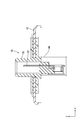
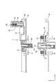
- FIG. 3 Top view of the fitting part between the inverter side terminal block and the motor side terminal block as seen from above Front view of the fitting part between the inverter side terminal block and the motor side terminal block as seen from the front FIG. 3 is a sectional view taken along the line III-III in FIG. Expanded cross section of the inverter side terminal block The expanded sectional view of the inverter side terminal block in the state where the first housing and the second housing are supported Enlarged sectional view of the motor side terminal block Sectional drawing showing the state before fitting an inverter side terminal block and a motor side terminal block Sectional drawing showing the state in the middle of fitting an inverter side terminal block and a motor side terminal block
- a connector 1 that electrically connects an inverter (not shown) and a motor (not shown) in a hybrid vehicle or an electric vehicle is illustrated.
- a part of each drawing shows an X axis, a Y axis, and a Z axis that are orthogonal to each other, and each axis direction is drawn in the direction shown in each drawing.
- the Z-axis direction coincides with the vertical direction with the upper side of the paper in FIGS.
- the upper side is the inverter side
- the lower side is the motor side
- the inverter is housed in the inverter case 10
- the motor is housed in the motor case 20.
- only the lower part covering the lower side of the inverter is illustrated for the inverter case 10
- only the upper part covering the upper side of the motor is illustrated for the motor case 20.
- the connector 1 of this embodiment is arranged in parallel in the Y-axis direction between the inverter side and the motor side, and connects between the two. Specifically, as shown in FIGS. 3 and 7, each connector 1 is arranged between an inverter-side terminal 82 and a motor-side terminal 92, which will be described later, and serves as a relay terminal that electrically connects the two. .
- the inverter-side terminal 82 is a male terminal that extends from the inverter side that is electrically connected to the inverter, and supplies AC power supplied from the inverter side to the motor. As shown in FIGS. 3 and 7, the inverter side terminal 82 is held in the inverter side housing 80 with the lower side as the connection side. The inverter-side housing 80 opens downward and is disposed above the lower portion of the inverter case 10.
- an inverter side rib 12 projecting downward in a rib shape and an inverter side opening surrounded by the inverter side rib 12 are formed in a part of the lower portion of the inverter case 10. 14 is provided.
- a motor-side rib 22 that protrudes upward in a rib shape and a motor-side opening 24 surrounded by the motor-side rib 22 are provided in a part of the upper portion of the motor case 20.
- the connector 1 includes an inverter-side terminal block 30, a motor-side terminal block 40, a first housing 50, a first terminal 52 held in the first housing 50, 2 housing 60, a second terminal 62 held in second housing 60, and a braided wire (an example of a conductive wire) 70 that connects between first terminal 52 and second terminal 62.
- the inverter side terminal block 30 is provided on the inverter side (upper side)
- the motor side terminal block 40 is provided on the motor side (lower side).
- the inverter-side terminal block 30 is a member that is smaller in size in plan view than the lower portion of the inverter case 10.
- the inverter side terminal block 30 is provided with a first attachment portion 32 and a second attachment portion 34.
- the 1st attachment part 32 has overlapped with the inverter side housing 80 in the up-down direction with the inverter side terminal block 30 as the lower side, and the second attachment part 34 will be described later with the inverter side terminal block 30 as the upper side. It overlaps with the motor-side housing 90 in the vertical direction.
- the first mounting portion 32 has a short cylindrical shape opening upward, and the surface of the lower opening edge is a first support surface 32A parallel to the XY plane.
- the second attachment portion 34 has a short cylindrical shape that opens downward, and an upper opening edge projects inward, and this projecting surface is a second support surface 34A that is parallel to the XY plane. Therefore, the first support surface 32A and the second support surface 34A are provided so as to be parallel to each other.
- the first housing 50 has a substantially cylindrical shape with the vertical direction as the cylinder axis direction. On the outer peripheral surface of the first housing 50 in the vicinity of the lower opening, there is provided a first projecting portion 51 projecting outward in parallel with the XY plane.
- a first terminal 52 On the upper opening side in the first housing 50, a first terminal 52, which is a female terminal, is held by a lance 54 that extends from the inner wall of the first housing 50 with its connection port facing upward. A part of the first terminal 52 opposite to the connection port extends to the vicinity of the lower opening along the inner wall of the first housing 50 and serves as a first connection portion 52A connected to a braided wire 70 described later. ing.
- the first housing 50 is attached to the first attachment portion 32 in such a manner that the first overhang portion 51 is addressed to the first support surface 32A of the first attachment portion 32, whereby the first support surface Floating supported with respect to 32A.
- the first housing 50 is slidably supported in the direction parallel to the first support surface 32A, that is, in the XY plane, by being floatingly supported on the first support surface 32A.
- the second housing 60 has substantially the same configuration as the first housing 50, and is attached to the second attachment portion 34 in an upside down posture with respect to the first housing 50. That is, the second housing 60 has a substantially cylindrical shape with the vertical direction as the cylinder axis direction, and a second tension projecting outward in parallel with the XY plane on the outer peripheral surface in the vicinity of the upper opening. A protruding portion 61 is provided.
- a second terminal 62 which is a female terminal, is held by a lance 64 extending from the inner wall of the second housing 60 on the lower opening side in the second housing 60 with its connection port facing downward. Yes.
- a part of the second terminal 62 opposite to the connection port extends to the vicinity of the upper opening along the inner wall of the second housing 60, and serves as a second connection portion 62A connected to a braided wire 70 described later. ing.
- the second overhanging portion 61 of the second housing 60 is addressed to the second support surface 34A of the second mounting portion 34. Further, an annular retainer member 72 is attached from the lower opening side of the second attachment portion 34 so that the second housing 60 is inserted inside the retainer member 72. Accordingly, the second housing 60 is attached to the second attachment portion 34 in such a manner that the second overhang portion 61 is sandwiched between the second support surface 34A and the retainer member 72, and the second support surface 34 Floating supported with respect to 34A.
- the second housing 60 is slidably supported in the direction parallel to the second support surface 34A, that is, in the XY plane, by being floatingly supported by the second support surface 34A.
- the braided wire 70 is a flexible conductive member and is slidable in the XY plane direction in the inverter side terminal block 30.
- the braided wire 70 is slidably arranged in the inverter-side terminal block 30 in each of the direction along the first support surface 32A and the direction along the second support surface 34A.
- the braided wire 70 is electrically connected to the first connection portion 52A of the first terminal 52 held at one end 70A in the first housing 50 and held at the other end 70B in the second housing 60.
- the second connection part 62 ⁇ / b> A of the second terminal 62 is electrically connected. Therefore, in the inverter side terminal block 30, the first terminal 52 and the second terminal 62 are electrically connected via the braided wire 70.
- the motor side terminal block 40 is arranged in a form to be placed on the upper portion of the motor case 20 as shown in FIGS. As shown in FIG. 7, the motor-side terminal block 40 is provided with a substantially plate-shaped main body portion 42 and a protruding portion 44 that protrudes vertically from a part of the main body portion 42.
- the motor-side terminal block 40 has a plate surface of the main body portion 42 placed on the motor-side rib 22 of the motor case 20 and a lower portion of the projecting portion 44 at the motor-side opening 24. In the inserted state, it is fixed to the motor case 20 by being fastened to the motor case 20 with a bolt B.
- a motor-side housing 90 that opens upward is provided on the upper portion of the protrusion 44 as shown in FIG.
- a motor side terminal 92 which is a male terminal is held with the upper side as a connection side.
- the motor side terminal 92 extends to the lower part of the motor side protruding portion 44 and is electrically connected to the motor, and supplies AC power converted by the inverter to the motor side.
- the connector 1 of the present embodiment has the above configuration, and the connection procedure will be described next.
- the main body of the motor side terminal block 40 is placed on the motor side rib 22 of the motor case 20 via the first seal member S1.
- the portion 42 is placed, and the lower side portion of the projecting portion 44 is inserted into the motor side opening 24 of the motor case 20 so that the motor side terminal block 40 is assembled to the motor case 20 and the space between the two is assembled. Fix it.
- the first seal member S ⁇ b> 1 is disposed between the main body portion 42 of the motor side terminal block 40 and the motor side rib 22. By doing so, the gap between the two is sealed. Thereby, it can prevent thru
- the first housing 50 is placed in the inverter side housing 80 from above the inverter side terminal block 30 with the first housing 50 and the second housing 60 attached in advance. Fit.
- the inverter-side terminal 82 and the first terminal 52 are male and female fitted in the vertical direction, and the two terminals are electrically connected.
- the lower surface of the inverter side terminal block 30 is directed to the lower inner wall of the inverter case 10, and the lower part of the second housing 60 is inserted into the inverter side opening 14 of the inverter case 10.
- the connector 1 is assembled
- the lower opening edge of the second mounting portion 34 coincides with the lower surface of the inverter-side terminal block 30 in the vertical direction. For this reason, when the connector 1 is assembled to the inverter case 10, the second mounting portion 34 does not interfere with the inverter case 10.
- the relative position in the XY plane direction between the inverter case 10 and the motor case 20 is determined.
- the inverter case 10 and the motor case 20 are each provided with a knock pin (not shown) and a bracket (not shown) on the other. By fitting these knock pins and brackets, the relative position in the XY plane direction between the inverter case 10 and the motor case 20 can be determined.
- the inverter side terminal block 30 assembled with the inverter case 10 is positioned between the inverter case 10 and the motor case 20, and then the motor side housing 90
- the second housing 60 is fitted into the bottom.
- the second terminal 62 and the motor side terminal 92 are male and female fitted in the vertical direction, and the two terminals are electrically connected.
- the second seal member S ⁇ b> 2 is disposed between the inverter side rib 12 and the main body 42 of the motor side terminal block 40. By doing so, seal between the two. Thereby, it is possible to prevent or suppress water or the like from entering between the inverter case 10 and the motor-side main body 42 (connection portion between the second terminal 62 and the motor-side terminal 92).
- the inverter-side terminal 82 and the motor-side terminal 92 are electrically connected via the connector 1, and AC power converted by the inverter is supplied to the motor.
- a downward force is applied to the motor side terminal block 40 due to the weight of the inverter side terminal block 30 itself. It is difficult for the motor-side terminal 92 to be disconnected in the vertical direction.
- both terminals 82 and 52 are caused due to component variations and assembly variations.
- the relative position between them may be displaced in the X-axis direction, the Y-axis direction, and the Z-axis direction.
- the inverter-side terminal 82 and the first terminal 52 are male-female fitted in a direction orthogonal to the first support surface 32A, that is, the Z-axis direction. By varying the degree, it is possible to absorb the positional deviation in the Z-axis direction.
- the first housing 50 in which the first terminal 52 is held is floatingly supported by the first support surface 32A, and the braided wire 70 connected to the first terminal 52 is the first support surface 32A. Since the first housing and the first terminal slide with the braided wire 70, the positional deviation in the X-axis direction and the Y-axis direction is possible. Can be absorbed.
- the motor side terminal 92 and the second terminal 62 are fitted, due to component variations and assembly variations, between the terminals 92 and 62. May shift in the X axis direction, the Y axis direction, and the Z axis direction.
- the motor-side terminal 92 and the second terminal 62 are male-female fitted in the direction orthogonal to the second support surface 34A, that is, the Z-axis direction. By varying the degree, it is possible to absorb the positional deviation in the Z-axis direction.
- the second housing 60 in which the second terminal 62 is held is floatingly supported by the second support surface 34A, and the braided wire 70 connected to the second terminal 62 is the second support surface 34A. Since the second housing 60 and the second terminal 62 slide together with the braided wire 70, the positions in the X-axis direction and the Y-axis direction are slidable in the direction along the X-Y plane. Misalignment can be absorbed.
- the X at the time of fitting in each of the fitting of the inverter side terminal 82 and the first terminal 52 and the fitting of the motor side terminal 92 and the second terminal 62 A positional shift in each of the axial direction, the Y-axis direction, and the Z-axis direction can be effectively absorbed.
- the relative position between the two terminals when the terminals are fitted to each other is Even if it is a position shift in each direction, between terminals can be satisfactorily fitted. As a result, the connection between the inverter and the motor can be facilitated.
- the braided wire 70 is disposed in the inverter side terminal block 30, and the first support surface 32 ⁇ / b> A and the second support surface 34 ⁇ / b> A are provided in parallel in the inverter side terminal block 30.
- the direction along the first support surface 32A and the direction along the second support surface 34A are the same direction, and therefore, in one plane direction (XY plane direction).
- the braided wire 70 may be slidably disposed only along the line, and the braided wire 70 can be easily disposed in the inverter-side terminal block 30.
- the inverter side terminal is a male terminal and the first terminal is a female terminal.
- the inverter side terminal is a female terminal, and the first terminal is a male terminal.
- mold terminal may be sufficient.
- the motor side terminal is a male terminal and the second terminal is a female terminal.
- the motor side terminal is a female terminal, and the second terminal is a male terminal.
- mold terminal may be sufficient.
- the braided wire is illustrated as an example of the conductive wire, but the configuration of the conductive wire is not limited.
Landscapes
- Engineering & Computer Science (AREA)
- Power Engineering (AREA)
- Transportation (AREA)
- Mechanical Engineering (AREA)
- Life Sciences & Earth Sciences (AREA)
- Sustainable Development (AREA)
- Sustainable Energy (AREA)
- Details Of Connecting Devices For Male And Female Coupling (AREA)
- Motor Or Generator Frames (AREA)
- Connector Housings Or Holding Contact Members (AREA)
- Inverter Devices (AREA)
Abstract
インバータ側端子台(30)内の第1支持面(32A)にフローティング支持される第1ハウジング(50)と、インバータ側端子台(30)内の第2支持面(34A)にフローティング支持される第2ハウジング(60)と、第1ハウジング(50)内に保持され、インバータ側端子(82)と第1支持面(32A)と直交する方向において雄雌嵌合される第1端子(52)と、第2ハウジング(60)内に保持され、モータ側端子台(40)に設けられたモータ側端子(92)と第2支持面(34A)と直交する方向において雄雌嵌合される第2端子(62)と、一端部が第1端子(52)と接続され、他端部が第2端子(62)と接続され、第1支持面(32A)に沿った方向と第2支持面(34A)に沿った方向との各々において摺動可能に配される編組線(70)と、を備える。
Description
本発明は、コネクタに関する。
従来、ハイブリッド自動車や電気自動車におけるインバータとモータとの間の接続において、パワーケーブル等のワイヤーハーネスを用いるものが知られている。また近年では、ワイヤーハーネスを用いることなく、インバータ側の端子とモータ側の端子とを嵌合させることで、インバータとモータとの間を直接接続するコネクタが知られている(特許文献1参照)。
ところで、上記特許文献1に記載されたコネクタのように、インバータとモータとの間を直接接続するコネクタにおいては、通常、インバータとモータとの間の相対位置が一旦位置決めされた後に、インバータ側の端子とモータ側の端子とが嵌合される。この場合、端子間を嵌合する際に、部品ばらつきや組付けばらつきに起因して、両端子間の相対位置が各方向に位置ずれすることがある。このような位置ずれが生じると、端子間を良好に嵌合し難いものとなり、端子間の接続が困難となる。
本発明は、上記の課題に鑑みて創作されたものであって、端子間を嵌合する際に両端子間の相対位置が各方向へ位置ずれすることを効果的に吸収することで、インバータとモータとの間の接続を容易にすることを目的とする。
本発明のコネクタは、インバータとモータとの間を接続するコネクタであって、前記インバータ側に設けられたインバータ側端子台と、前記モータ側に設けられたモータ側端子台と、前記インバータ側端子台内に設けられた第1支持面にフローティング支持される第1ハウジングと、前記インバータ側端子台内に設けられた第2支持面にフローティング支持される第2ハウジングと、前記第1ハウジング内に保持され、前記インバータからの交流電源を供給するインバータ側端子と前記第1支持面と直交する方向において雄雌嵌合される第1端子と、前記第2ハウジング内に保持され、前記モータ側端子台に設けられたモータ側端子と前記第2支持面と直交する方向において雄雌嵌合される第2端子と、可撓性を有し、一端部が前記第1端子と接続され、他端部が前記第2端子と接続されるとともに、前記第1支持面に沿った方向と前記第2支持面に沿った方向との各々において摺動可能に配される導電線と、を備えることを特徴とする。
上記のコネクタでは、第1端子がインバータ側端子に対して第1支持面と直交する方向において雄雌嵌合されるため、第1端子とインバータ側端子とを嵌合する際に両端子間の相対位置が第1支持面と直交する方向について位置ずれした場合、雄雌嵌合の嵌合の程度が変動することによってその位置ずれを吸収することができる。さらに、第1ハウジングが第1支持面にフローティング支持され、第1ハウジング内に保持された第1端子と接続された導電線が第1支持面に沿った方向に摺動可能とされている。このため、第1端子とインバータ側端子とを嵌合する際に両端子間の相対位置が第1支持面に沿った方向について位置ずれした場合、第1ハウジングと第1端子が導電線と共に第1支持面に沿った方向に摺動し、その位置ずれを吸収することができる。
一方、第2端子はモータ側端子に対して第2支持面と直交する方向において雄雌嵌合されるため、第2端子とモータ側端子とを嵌合する際に両端子間の相対位置が第2支持面と直交する方向について位置ずれした場合、雄雌嵌合の嵌合の程度が変動することによってその位置ずれを吸収することができる。さらに、第2ハウジングが第2支持面にフローティング支持され、第2ハウジング内に保持された第2端子と接続された導電線が第2支持面に沿った方向に摺動可能とされている。このため、第2端子とモータ側端子とを嵌合する際に両端子間の相対位置が第2支持面に沿った方向について位置ずれした場合、第2ハウジングと第2端子が導電線と共に第2支持面に沿った方向に摺動し、その位置ずれを吸収することができる。このように上記のコネクタでは、インバータ側端子と第1端子との嵌合、及びモータ側端子と第2端子との嵌合の各々において、端子間を嵌合する際に両端子間の相対位置が各方向へ位置ずれすることを効果的に吸収することで、インバータとモータとの間の接続を容易にすることができる。
上記のコネクタにおいて、前記導電線は前記インバータ端子台内に配され、前記インバータ側端子台において前記第1支持面と前記第2支持面とが平行に設けられていてもよい。
この構成によると、第1支持面に沿った方向と第2支持面に沿った方向とが同一方向となるため、インバータ端子台内において導電線を配し易いものとすることができる。
本発明によれば、端子間を嵌合する際に両端子間の相対位置が各方向へ位置ずれすることを効果的に吸収することで、インバータとモータとの間の接続を容易にすることができる。
図面を参照して実施形態を説明する。本実施形態では、例えばハイブリッド自動車や電気自動車において、図示しないインバータと図示しないモータとの間を電気的に接続するコネクタ1について例示する。なお、各図面の一部には、互いに直交するX軸、Y軸及びZ軸を示しており、各軸方向が各図面で示した方向となるように描かれている。このうちZ軸方向は、図2乃至図8における紙面上側を上方として、上下方向と一致している。
本実施形態では、上側をインバータ側とし、下側をモータ側として、インバータがインバータケース10内に収容され、モータがモータケース20内に収容される。なお、各図面では、インバータケース10についてはインバータの下側を覆う下側部分のみを図示しており、モータケース20についてはモータの上側を覆う上側部分のみを図示している。
本実施形態のコネクタ1は、図1及び図2に示すように、インバータ側とモータ側との間にY軸方向に沿って6つ並列した形で配され、両者の間を接続する。具体的には、各コネクタ1は、図3及び図7に示すように、後述するインバータ側端子82とモータ側端子92との間に配され、両者を電気的に接続する中継端子とされる。
先に、インバータ側端子82、インバータケース10、及びモータケース20の各構成について説明する。インバータ側端子82は、インバータと電気的に接続されたインバータ側から延びる雄型端子であり、インバータ側から供給された交流電源をモータへ供給する。インバータ側端子82は、図3及び図7に示すように、下側を接続側としてインバータ側ハウジング80内に保持されている。インバータ側ハウジング80は、下方に開口しており、インバータケース10の下側部分よりも上方に配されている。
インバータケース10の下側部分の一部には、図3及び図7に示すように、下方に向かってリブ状に突出するインバータ側リブ12と、このインバータ側リブ12によって囲まれるインバータ側開口部14とが設けられている。一方、モータケース20の上側部分の一部には、上方に向かってリブ状に突出するモータ側リブ22と、このモータ側リブ22によって囲まれるモータ側開口部24とが設けられている。
次にコネクタ1の構成について説明する。コネクタ1は、図3及び図7に示すように、インバータ側端子台30と、モータ側端子台40と、第1ハウジング50と、第1ハウジング50内に保持される第1端子52と、第2ハウジング60と、第2ハウジング60内に保持される第2端子62と、第1端子52と第2端子62との間を接続する編組線(導電線の一例)70と、を備える。このうちインバータ側端子台30はインバータ側(上側)に設けられ、モータ側端子台40はモータ側(下側)に設けられている。
インバータ側端子台30は、図1に示すように、平面に視た大きさがインバータケース10の下側部分よりも小さな部材とされる。インバータ側端子台30には、図4に示すように、第1取付部32と、第2取付部34とが設けられている。このうち第1取付部32は、インバータ側端子台30を下側として、インバータ側ハウジング80と上下方向において重畳しており、第2取付部34は、インバータ側端子台30を上側として、後述するモータ側ハウジング90と上下方向において重畳している。
図4に示すように、第1取付部32は、上方に開口する短い筒状をなしており、下部開口縁の面がX-Y平面に平行な第1支持面32Aとされている。一方、第2取付部34は、下方に開口する短い筒状をなすとともに上部開口縁が内側に張り出しており、この張り出し面がX-Y平面に平行な第2支持面34Aとされている。従って、第1支持面32Aと第2支持面34Aは、互いに平行となるように設けられている。
第1ハウジング50は、図5に示すように、上下方向を筒軸方向とする略筒状をなしている。第1ハウジング50の下部開口近傍の外周面には、外側に向かってX-Y平面に平行に張り出す第1張出部51が設けられている。
第1ハウジング50内における上部開口側には、雌型端子である第1端子52がその接続口を上方に向けた形で、当該第1ハウジング50の内壁から延びるランス54によって保持されている。第1端子52の上記接続口とは反対側の一部は、第1ハウジング50の内壁に沿って下部開口近傍まで延びており、後述する編組線70と接続される第1接続部52Aとされている。
第1ハウジング50は、その第1張出部51が第1取付部32の第1支持面32Aに宛がわれた形で第1取付部32に取り付けられており、これにより、第1支持面32Aに対してフローティング支持されている。第1ハウジング50は、第1支持面32Aにフローティング支持されることで、第1支持面32Aと平行な方向、即ちX-Y平面に摺動可能とされている。
第2ハウジング60は、図5に示すように、第1ハウジング50とほぼ同様の構成とされ、第1ハウジング50とは上下逆の姿勢で第2取付部34に取り付けられている。即ち、第2ハウジング60は、上下方向を筒軸方向とする略筒状をなしており、その上部開口近傍の外周面には、外側に向かってX-Y平面に平行に張り出す第2張出部61が設けられている。
そして、第2ハウジング60内における下部開口側には、雌型端子である第2端子62がその接続口を下方に向けた形で、当該第2ハウジング60の内壁から延びるランス64によって保持されている。第2端子62の上記接続口とは反対側の一部は、第2ハウジング60の内壁に沿って上部開口近傍まで延びており、後述する編組線70と接続される第2接続部62Aとされている。
第2ハウジング60は、その第2張出部61が第2取付部34の第2支持面34Aに宛がわれている。さらに、環状をなすリテーナ部材72が、その内側に第2ハウジング60が挿通される形で第2取付部34の下部開口側から取り付けられている。これにより、第2ハウジング60は、その第2張出部61が第2支持面34Aとリテーナ部材72との間に挟持された形で第2取付部34に取り付けられており、第2支持面34Aに対してフローティング支持されている。第2ハウジング60は、第2支持面34Aにフローティング支持されることで、第2支持面34Aと平行な方向、即ちX-Y平面に摺動可能とされている。
編組線70は、可撓性を有する導電部材であり、インバータ側端子台30内においてX-Y平面方向に摺動可能に引き回されている。換言すれば、編組線70は、インバータ側端子台30内において第1支持面32Aに沿った方向と第2支持面34Aに沿った方向との各々において摺動可能に配されている。
また、編組線70は、その一端部70Aが第1ハウジング50内に保持された第1端子52の第1接続部52Aと電気的に接続され、その他端部70Bが第2ハウジング60内に保持された第2端子62の第2接続部62Aと電気的に接続されている。従って、インバータ側端子台30内において、第1端子52と第2端子62の間は、編組線70を介して電気的に接続されている。
モータ側端子台40は、図1及び図2に示すように、モータケース20の上側部分に載置される形で配される。モータ側端子台40には、図7に示すように、略板状をなす本体部42と、本体部42の一部から上下方向に突出する突出部44と、が設けられている。
モータ側端子台40は、図2に示すように、本体部42の板面がモータケース20のモータ側リブ22上に載置されるとともに突出部44の下側部分がモータ側開口部24に挿通された状態で、ボルトBによってモータケース20と締結されることで、モータケース20に対して固定されている。
モータ側端子台40において突出部44の上側部分には、図6に示すように、上方に開口するモータ側ハウジング90が設けられている。モータ側ハウジング90内には、雄型端子であるモータ側端子92が上側を接続側として保持されている。モータ側端子92は、モータ側突出部44の下側部分まで延びてモータと電気的に接続されており、インバータで変換された交流電源をモータ側へ供給する。
本実施形態のコネクタ1は以上のような構成であり、続いてその接続手順について説明する。コネクタ1を用いてインバータとモータとの間を接続する場合、まず、図7に示すように、モータケース20のモータ側リブ22上に第1シール部材S1を介してモータ側端子台40の本体部42を載置するとともに、突出部44の下側部分をモータケース20のモータ側開口部24に挿通させることで、モータ側端子台40をモータケース20に対して組付け、両者の間を固定する。
なお、図3に示すように、モータ側端子台40をモータケース20に対して組付ける際、モータ側端子台40の本体部42とモータ側リブ22との間に第1シール部材S1を配することで、両者の間をシールする。これにより、モータ側本体部42とモータ側リブ22との間(モータケース20内)に水等が浸入することを防止ないし抑制することができる。
次に、図8に示すように、第1ハウジング50と第2ハウジング60とが予め取り付けられた状態のインバータ側端子台30に対して、インバータ側ハウジング80内に第1ハウジング50をその上方から嵌め入れる。これにより、インバータ側端子82と第1端子52とが上下方向において雄雌嵌合され、両端子間が電気的に接続される。
次に、図8に示すように、インバータ側端子台30の下面をインバータケース10の下部内壁に宛がうとともに、第2ハウジング60の下側部分をインバータケース10のインバータ側開口部14に挿通させることで、コネクタ1をインバータケース10に対して組付け、両者の間を固定する。なお、インバータ側端子台30では、第2取付部34の下部開口縁がインバータ側端子台30の下面と上下方向において一致している。このため、コネクタ1をインバータケース10に対して組付ける際、第2取付部34がインバータケース10と干渉しないものとなっている。
次に、インバータケース10とモータケース20との間のX-Y平面方向の相対位置について位置決めをする。ここで本実施形態では、インバータケース10とモータケース20について、いずれか一方に図示しないノックピンが設けられ、いずれか他方に図示しないブラケットが設けられている。これらのノックピンとブラケットを嵌合させることで、インバータケース10とモータケース20との間のX-Y平面方向の相対位置について位置決めをすることができる。
次に、図3に示すように、インバータケース10と組付けられた状態のインバータ側端子台30について、上記インバータケース10とモータケース20との間の位置決めを行った後、モータ側ハウジング90内に第2ハウジング60をその下方から嵌め入れる。これにより、第2端子62とモータ側端子92とが上下方向に雄雌嵌合され、両端子間が電気的に接続される。
なお、図3に示すように、第2端子62とモータ側端子92とを接続する際、インバータ側リブ12とモータ側端子台40の本体部42との間に第2シール部材S2を配することで、両者の間をシールする。これにより、インバータケース10とモータ側本体部42との間(第2端子62とモータ側端子92との接続部分)に水等が浸入することを防止ないし抑制することができる。
以上のような接続手順により、インバータ側端子82とモータ側端子92との間がコネクタ1を介して電気的に接続され、インバータで変換された交流電源がモータに供給される。なお、第2端子62とモータ側端子92との間が接続された状態では、インバータ側端子台30自体の重みによってモータ側端子台40に対して下向きの力が加わるため、第2端子62とモータ側端子92との間が上下方向において外れ難いものとされる。
以上説明した本実施形態に係るコネクタ1では、上記の接続手順において、インバータ側端子82と第1端子52とを嵌合する際、部品ばらつきや組付けばらつきに起因して、両端子82、52間の相対位置がX軸方向、Y軸方向、及びZ軸方向の各方向に位置ずれすることがある。この点、本実施形態では、インバータ側端子82と第1端子52とが第1支持面32Aと直交する方向、即ちZ軸方向において雄雌嵌合されるため、雄雌嵌合の嵌合の程度が変動することによって、Z軸方向における位置ずれを吸収することができる。さらに本実施形態では、内部に第1端子52が保持された第1ハウジング50が第1支持面32Aにフローティング支持され、かつ、第1端子52と接続された編組線70が第1支持面32Aに沿った方向、即ちX-Y平面方向に摺動可能とされているため、第1ハウジングと第1端子が編組線70と共に摺動することによって、X軸方向及びY軸方向についての位置ずれを吸収することができる。
さらに、本実施形態に係るコネクタ1において、上記の接続手順では、モータ側端子92と第2端子62とを嵌合する際、部品ばらつきや組付けばらつきに起因して、両端子92、62間の相対位置がX軸方向、Y軸方向、及びZ軸方向の各方向に位置ずれすることがある。この点、本実施形態では、モータ側端子92と第2端子62とが第2支持面34Aと直交する方向、即ちZ軸方向において雄雌嵌合されるため、雄雌嵌合の嵌合の程度が変動することによって、Z軸方向における位置ずれを吸収することができる。さらに本実施形態では、内部に第2端子62が保持された第2ハウジング60が第2支持面34Aにフローティング支持され、かつ、第2端子62と接続された編組線70が第2支持面34Aに沿った方向、即ちX-Y平面方向に摺動可能とされているため、第2ハウジング60第2端子62が編組線70と共に摺動することによって、X軸方向及びY軸方向についての位置ずれを吸収することができる。
以上のように本実施形態のコネクタ1では、インバータ側端子82と第1端子52との嵌合、及びモータ側端子92と第2端子62との嵌合の各々において、嵌合する際におけるX軸方向、Y軸方向、及びZ軸方向の各方向への位置ずれを効果的に吸収することができる。このため、インバータ側端子82と第1端子52との嵌合、及びモータ側端子92と第2端子62との嵌合の各々において、端子間を嵌合する際に両端子間の相対位置が各方向に位置ずれした場合であっても、端子間を良好に嵌合させることができる。その結果、インバータとモータとの間の接続を容易にすることができる。
また、本実施形態のコネクタ1では、編組線70がインバータ側端子台30内に配され、インバータ側端子台30において第1支持面32Aと第2支持面34Aとが平行に設けられている。このような構成とされていることで、第1支持面32Aに沿った方向と第2支持面34Aに沿った方向とが同一方向となるため、一つの平面方向(X-Y平面方向)に沿ってのみ編組線70を摺動可能に配すればよく、インバータ側端子台30内において編組線70を配し易いものとすることができる。
上記の実施形態の変形例を以下に列挙する。
(1)上記の実施形態では、インバータ側端子台において第1支持面と第2支持面とが平行に設けられた構成を例示したが、インバータ側端子台において第1支持面と第2支持面とが非平行に設けられた構成であってもよい。
(1)上記の実施形態では、インバータ側端子台において第1支持面と第2支持面とが平行に設けられた構成を例示したが、インバータ側端子台において第1支持面と第2支持面とが非平行に設けられた構成であってもよい。
(2)上記の実施形態では、インバータ側端子が雄型端子とされ、第1端子が雌型端子とされた構成を例示したが、インバータ側端子が雌型端子とされ、第1端子が雄型端子とされた構成であってもよい。
(3)上記の実施形態では、モータ側端子が雄型端子とされ、第2端子が雌型端子とされた構成を例示したが、モータ側端子が雌型端子とされ、第2端子が雄型端子とされた構成であってもよい。
(4)上記の実施形態では、インバータ側端子台において第2ハウジングがリテーナ部材によって支持される構成を例示したが、インバータ側端子台における第1ハウジング及び第2ハウジングの支持態様については限定されない。
(5)上記の実施形態では、導電線の一例として編組線を例示したが、導電線の構成については限定されない。
以上、本発明の各実施形態について詳細に説明したが、これらは例示に過ぎず、特許請求の範囲を限定するものではない。特許請求の範囲に記載の技術には、以上に例示した具体例を様々に変形、変更したものが含まれる。
1…コネクタ
10…インバータケース
20…モータケース
30…インバータ側端子台
32…第1取付部
32A…第1支持面
34…第2取付部
34A…第2支持面
40…モータ側端子台
50…第1ハウジング
52…第1端子
60…第2ハウジング
62…第2端子
70…編組線
72…リテーナ部材
80…インバータ側ハウジング
82…インバータ側端子
90…モータ側ハウジング
92…モータ側端子
10…インバータケース
20…モータケース
30…インバータ側端子台
32…第1取付部
32A…第1支持面
34…第2取付部
34A…第2支持面
40…モータ側端子台
50…第1ハウジング
52…第1端子
60…第2ハウジング
62…第2端子
70…編組線
72…リテーナ部材
80…インバータ側ハウジング
82…インバータ側端子
90…モータ側ハウジング
92…モータ側端子
Claims (2)
- インバータとモータとの間を接続するコネクタであって、
前記インバータ側に設けられたインバータ側端子台と、
前記モータ側に設けられたモータ側端子台と、
前記インバータ側端子台内に設けられた第1支持面にフローティング支持される第1ハウジングと、
前記インバータ側端子台内に設けられた第2支持面にフローティング支持される第2ハウジングと、
前記第1ハウジング内に保持され、前記インバータからの交流電源を供給するインバータ側端子と前記第1支持面と直交する方向において雄雌嵌合される第1端子と、
前記第2ハウジング内に保持され、前記モータ側端子台に設けられたモータ側端子と前記第2支持面と直交する方向において雄雌嵌合される第2端子と、
可撓性を有し、一端部が前記第1端子と接続され、他端部が前記第2端子と接続されるとともに、前記第1支持面に沿った方向と前記第2支持面に沿った方向との各々において摺動可能に配される導電線と、
を備えることを特徴とするコネクタ。 - 前記導電線は前記インバータ端子台内に配され、
前記インバータ側端子台において前記第1支持面と前記第2支持面とが平行に設けられていることを特徴とする請求項1に記載のコネクタ。
Priority Applications (3)
| Application Number | Priority Date | Filing Date | Title |
|---|---|---|---|
| CN201480065911.0A CN105814755B (zh) | 2013-12-13 | 2014-11-28 | 连接器 |
| EP14870032.1A EP3082201B1 (en) | 2013-12-13 | 2014-11-28 | Connector |
| US15/038,481 US9698528B2 (en) | 2013-12-13 | 2014-11-28 | Connector for directly connecting an inverter and a motor |
Applications Claiming Priority (2)
| Application Number | Priority Date | Filing Date | Title |
|---|---|---|---|
| JP2013-257780 | 2013-12-13 | ||
| JP2013257780A JP5967063B2 (ja) | 2013-12-13 | 2013-12-13 | コネクタ |
Publications (1)
| Publication Number | Publication Date |
|---|---|
| WO2015087717A1 true WO2015087717A1 (ja) | 2015-06-18 |
Family
ID=53371028
Family Applications (1)
| Application Number | Title | Priority Date | Filing Date |
|---|---|---|---|
| PCT/JP2014/081532 Ceased WO2015087717A1 (ja) | 2013-12-13 | 2014-11-28 | コネクタ |
Country Status (5)
| Country | Link |
|---|---|
| US (1) | US9698528B2 (ja) |
| EP (1) | EP3082201B1 (ja) |
| JP (1) | JP5967063B2 (ja) |
| CN (1) | CN105814755B (ja) |
| WO (1) | WO2015087717A1 (ja) |
Cited By (3)
| Publication number | Priority date | Publication date | Assignee | Title |
|---|---|---|---|---|
| CN107634379A (zh) * | 2016-07-19 | 2018-01-26 | 住友电装株式会社 | 连接器 |
| JPWO2021124491A1 (ja) * | 2019-12-18 | 2021-06-24 | ||
| DE102018208334B4 (de) | 2017-06-02 | 2023-08-03 | Yazaki Corporation | Verbindungseinrichtungsmontagestruktur und anschlussstufe |
Families Citing this family (12)
| Publication number | Priority date | Publication date | Assignee | Title |
|---|---|---|---|---|
| CN106299781B (zh) * | 2016-08-10 | 2018-12-28 | 深圳市深台帏翔电子有限公司 | 连接器 |
| DE102017207215A1 (de) * | 2017-04-28 | 2018-10-31 | Zf Friedrichshafen Ag | Anschlusseinrichtung |
| JP6317844B1 (ja) * | 2017-05-30 | 2018-04-25 | イリソ電子工業株式会社 | コネクタ |
| JP6848722B2 (ja) * | 2017-06-27 | 2021-03-24 | 住友電装株式会社 | コネクタ及びコネクタの取付構造 |
| JP6822922B2 (ja) | 2017-08-14 | 2021-01-27 | トヨタ自動車株式会社 | 電子機器の車載構造 |
| BE1026231B1 (de) * | 2018-04-24 | 2019-11-25 | Phoenix Contact Gmbh & Co | Elektrischer verbinder |
| DE102020200584A1 (de) | 2020-01-20 | 2021-07-22 | Continental Teves Ag & Co. Ohg | Stecksystem zur elektrischen Verbindung von elektronischen Baugruppen und Druckbereitstellungseinrichtung mit einem Stecksystem |
| CN113745905B (zh) * | 2020-05-29 | 2024-03-29 | 庆虹电子(苏州)有限公司 | 连接器装置及连接器浮动模块 |
| CN114336117B (zh) * | 2020-09-30 | 2024-05-31 | 台达电子工业股份有限公司 | 转接连接器 |
| JP2022071603A (ja) * | 2020-10-28 | 2022-05-16 | 住友電装株式会社 | コネクタ |
| JP7563269B2 (ja) * | 2021-03-26 | 2024-10-08 | マツダ株式会社 | 電動車両の下部構造 |
| JP2025062858A (ja) * | 2023-10-03 | 2025-04-15 | 株式会社オートネットワーク技術研究所 | 中継コネクタ、端子台モジュール、コイルエンドモジュール及び接続モジュール |
Citations (5)
| Publication number | Priority date | Publication date | Assignee | Title |
|---|---|---|---|---|
| WO2011016272A1 (ja) * | 2009-08-03 | 2011-02-10 | 矢崎総業株式会社 | コネクタ |
| WO2011055806A1 (ja) * | 2009-11-06 | 2011-05-12 | 矢崎総業株式会社 | モータケースに設置されたインバータ端子台 |
| JP2011187224A (ja) | 2010-03-05 | 2011-09-22 | Yazaki Corp | モータケースに設置されたインバータ端子台 |
| WO2012056909A1 (ja) * | 2010-10-25 | 2012-05-03 | 矢崎総業株式会社 | 機器接続用コネクタ構造 |
| WO2012137766A1 (ja) * | 2011-04-05 | 2012-10-11 | 株式会社オートネットワーク技術研究所 | コネクタ |
Family Cites Families (5)
| Publication number | Priority date | Publication date | Assignee | Title |
|---|---|---|---|---|
| JP3984579B2 (ja) * | 2003-09-16 | 2007-10-03 | 株式会社オートネットワーク技術研究所 | インバータ用コネクタ装置 |
| FR2897206B1 (fr) * | 2006-02-03 | 2008-03-21 | Mge Ups Systems Soc Par Action | Dispositif de branchement en parallele d'une pluralite d'appareils d'alimentation electrique |
| JP4665848B2 (ja) * | 2006-03-15 | 2011-04-06 | 日立電線株式会社 | コネクタ構造 |
| JP4840671B2 (ja) * | 2008-10-29 | 2011-12-21 | アイシン・エィ・ダブリュ株式会社 | 電気的接続構造 |
| DE102009029545A1 (de) * | 2009-09-17 | 2011-03-31 | Robert Bosch Gmbh | Steckverbindung |
-
2013
- 2013-12-13 JP JP2013257780A patent/JP5967063B2/ja not_active Expired - Fee Related
-
2014
- 2014-11-28 EP EP14870032.1A patent/EP3082201B1/en not_active Not-in-force
- 2014-11-28 US US15/038,481 patent/US9698528B2/en not_active Expired - Fee Related
- 2014-11-28 WO PCT/JP2014/081532 patent/WO2015087717A1/ja not_active Ceased
- 2014-11-28 CN CN201480065911.0A patent/CN105814755B/zh not_active Expired - Fee Related
Patent Citations (5)
| Publication number | Priority date | Publication date | Assignee | Title |
|---|---|---|---|---|
| WO2011016272A1 (ja) * | 2009-08-03 | 2011-02-10 | 矢崎総業株式会社 | コネクタ |
| WO2011055806A1 (ja) * | 2009-11-06 | 2011-05-12 | 矢崎総業株式会社 | モータケースに設置されたインバータ端子台 |
| JP2011187224A (ja) | 2010-03-05 | 2011-09-22 | Yazaki Corp | モータケースに設置されたインバータ端子台 |
| WO2012056909A1 (ja) * | 2010-10-25 | 2012-05-03 | 矢崎総業株式会社 | 機器接続用コネクタ構造 |
| WO2012137766A1 (ja) * | 2011-04-05 | 2012-10-11 | 株式会社オートネットワーク技術研究所 | コネクタ |
Cited By (5)
| Publication number | Priority date | Publication date | Assignee | Title |
|---|---|---|---|---|
| CN107634379A (zh) * | 2016-07-19 | 2018-01-26 | 住友电装株式会社 | 连接器 |
| DE102018208334B4 (de) | 2017-06-02 | 2023-08-03 | Yazaki Corporation | Verbindungseinrichtungsmontagestruktur und anschlussstufe |
| JPWO2021124491A1 (ja) * | 2019-12-18 | 2021-06-24 | ||
| WO2021124491A1 (ja) * | 2019-12-18 | 2021-06-24 | トヨタ自動車株式会社 | 電線側コネクタ |
| JP7273189B2 (ja) | 2019-12-18 | 2023-05-12 | トヨタ自動車株式会社 | 電線側コネクタ |
Also Published As
| Publication number | Publication date |
|---|---|
| EP3082201A1 (en) | 2016-10-19 |
| EP3082201A4 (en) | 2016-11-30 |
| JP2015115251A (ja) | 2015-06-22 |
| CN105814755A (zh) | 2016-07-27 |
| JP5967063B2 (ja) | 2016-08-10 |
| CN105814755B (zh) | 2018-02-13 |
| US9698528B2 (en) | 2017-07-04 |
| US20160301160A1 (en) | 2016-10-13 |
| EP3082201B1 (en) | 2019-11-27 |
Similar Documents
| Publication | Publication Date | Title |
|---|---|---|
| JP5967063B2 (ja) | コネクタ | |
| JP6135502B2 (ja) | コネクタ | |
| JP6247604B2 (ja) | 防水コネクタ | |
| JP6225836B2 (ja) | コネクタ構造 | |
| JP5067199B2 (ja) | 車載用の電気接続箱 | |
| JP5978106B2 (ja) | コネクタ間の接続構造 | |
| JP2014086349A (ja) | コネクタ | |
| JP6936970B2 (ja) | 筐体内回路体に対するワイヤハーネスの接続構造 | |
| CN107302277B (zh) | 电动机的防水结构 | |
| US20160233609A1 (en) | Connector | |
| WO2015098512A1 (ja) | 導電部材 | |
| JP6209997B2 (ja) | 車載電気機器 | |
| JP6520425B2 (ja) | 機器用弾性シールド部材 | |
| JP2016213053A (ja) | パッキン、コネクタ及びワイヤハーネス | |
| JP6052155B2 (ja) | コネクタ | |
| JP2014054035A (ja) | 電気接続箱の防水部材 | |
| JP7107659B2 (ja) | 電気接続箱 | |
| JP2015115252A (ja) | コネクタ | |
| JP6499142B2 (ja) | 接続装置 | |
| JP2017103155A (ja) | コネクタ | |
| JP2014235969A (ja) | 中継用コネクタユニット | |
| JP2013080633A (ja) | ケーブル用コネクタ |
Legal Events
| Date | Code | Title | Description |
|---|---|---|---|
| 121 | Ep: the epo has been informed by wipo that ep was designated in this application |
Ref document number: 14870032 Country of ref document: EP Kind code of ref document: A1 |
|
| REEP | Request for entry into the european phase |
Ref document number: 2014870032 Country of ref document: EP |
|
| WWE | Wipo information: entry into national phase |
Ref document number: 2014870032 Country of ref document: EP |
|
| WWE | Wipo information: entry into national phase |
Ref document number: 15038481 Country of ref document: US |
|
| NENP | Non-entry into the national phase |
Ref country code: DE |