WO2015087975A1 - 風向調整装置 - Google Patents
風向調整装置 Download PDFInfo
- Publication number
- WO2015087975A1 WO2015087975A1 PCT/JP2014/082863 JP2014082863W WO2015087975A1 WO 2015087975 A1 WO2015087975 A1 WO 2015087975A1 JP 2014082863 W JP2014082863 W JP 2014082863W WO 2015087975 A1 WO2015087975 A1 WO 2015087975A1
- Authority
- WO
- WIPO (PCT)
- Prior art keywords
- fin
- fins
- air blowing
- blowing mode
- link mechanism
- Prior art date
- Legal status (The legal status is an assumption and is not a legal conclusion. Google has not performed a legal analysis and makes no representation as to the accuracy of the status listed.)
- Ceased
Links
Images







Classifications
-
- F—MECHANICAL ENGINEERING; LIGHTING; HEATING; WEAPONS; BLASTING
- F24—HEATING; RANGES; VENTILATING
- F24F—AIR-CONDITIONING; AIR-HUMIDIFICATION; VENTILATION; USE OF AIR CURRENTS FOR SCREENING
- F24F13/00—Details common to, or for air-conditioning, air-humidification, ventilation or use of air currents for screening
- F24F13/08—Air-flow control members, e.g. louvres, grilles, flaps or guide plates
- F24F13/10—Air-flow control members, e.g. louvres, grilles, flaps or guide plates movable, e.g. dampers
- F24F13/14—Air-flow control members, e.g. louvres, grilles, flaps or guide plates movable, e.g. dampers built up of tilting members, e.g. louvre
- F24F13/15—Air-flow control members, e.g. louvres, grilles, flaps or guide plates movable, e.g. dampers built up of tilting members, e.g. louvre with parallel simultaneously tiltable lamellae
-
- B—PERFORMING OPERATIONS; TRANSPORTING
- B60—VEHICLES IN GENERAL
- B60H—ARRANGEMENTS OF HEATING, COOLING, VENTILATING OR OTHER AIR-TREATING DEVICES SPECIALLY ADAPTED FOR PASSENGER OR GOODS SPACES OF VEHICLES
- B60H1/00—Heating, cooling or ventilating devices
- B60H1/34—Nozzles; Air-diffusers
-
- B—PERFORMING OPERATIONS; TRANSPORTING
- B60—VEHICLES IN GENERAL
- B60H—ARRANGEMENTS OF HEATING, COOLING, VENTILATING OR OTHER AIR-TREATING DEVICES SPECIALLY ADAPTED FOR PASSENGER OR GOODS SPACES OF VEHICLES
- B60H1/00—Heating, cooling or ventilating devices
- B60H1/00642—Control systems or circuits; Control members or indication devices for heating, cooling or ventilating devices
- B60H1/00814—Control systems or circuits characterised by their output, for controlling particular components of the heating, cooling or ventilating installation
- B60H1/00821—Control systems or circuits characterised by their output, for controlling particular components of the heating, cooling or ventilating installation the components being ventilating, air admitting or air distributing devices
- B60H1/00871—Air directing means, e.g. blades in an air outlet
-
- B—PERFORMING OPERATIONS; TRANSPORTING
- B60—VEHICLES IN GENERAL
- B60H—ARRANGEMENTS OF HEATING, COOLING, VENTILATING OR OTHER AIR-TREATING DEVICES SPECIALLY ADAPTED FOR PASSENGER OR GOODS SPACES OF VEHICLES
- B60H1/00—Heating, cooling or ventilating devices
- B60H1/34—Nozzles; Air-diffusers
- B60H1/3407—Nozzles; Air-diffusers providing an air stream in a fixed direction, e.g. using a grid or porous panel
-
- B—PERFORMING OPERATIONS; TRANSPORTING
- B60—VEHICLES IN GENERAL
- B60H—ARRANGEMENTS OF HEATING, COOLING, VENTILATING OR OTHER AIR-TREATING DEVICES SPECIALLY ADAPTED FOR PASSENGER OR GOODS SPACES OF VEHICLES
- B60H1/00—Heating, cooling or ventilating devices
- B60H1/34—Nozzles; Air-diffusers
- B60H1/3414—Nozzles; Air-diffusers with means for adjusting the air stream direction
-
- B—PERFORMING OPERATIONS; TRANSPORTING
- B60—VEHICLES IN GENERAL
- B60H—ARRANGEMENTS OF HEATING, COOLING, VENTILATING OR OTHER AIR-TREATING DEVICES SPECIALLY ADAPTED FOR PASSENGER OR GOODS SPACES OF VEHICLES
- B60H1/00—Heating, cooling or ventilating devices
- B60H1/34—Nozzles; Air-diffusers
- B60H1/3414—Nozzles; Air-diffusers with means for adjusting the air stream direction
- B60H1/3421—Nozzles; Air-diffusers with means for adjusting the air stream direction using only pivoting shutters
-
- B—PERFORMING OPERATIONS; TRANSPORTING
- B60—VEHICLES IN GENERAL
- B60H—ARRANGEMENTS OF HEATING, COOLING, VENTILATING OR OTHER AIR-TREATING DEVICES SPECIALLY ADAPTED FOR PASSENGER OR GOODS SPACES OF VEHICLES
- B60H1/00—Heating, cooling or ventilating devices
- B60H1/34—Nozzles; Air-diffusers
- B60H1/345—Nozzles; Air-diffusers with means for adjusting divergence, convergence or oscillation of air stream
-
- F—MECHANICAL ENGINEERING; LIGHTING; HEATING; WEAPONS; BLASTING
- F24—HEATING; RANGES; VENTILATING
- F24F—AIR-CONDITIONING; AIR-HUMIDIFICATION; VENTILATION; USE OF AIR CURRENTS FOR SCREENING
- F24F13/00—Details common to, or for air-conditioning, air-humidification, ventilation or use of air currents for screening
- F24F13/02—Ducting arrangements
- F24F13/06—Outlets for directing or distributing air into rooms or spaces, e.g. ceiling air diffuser
-
- F—MECHANICAL ENGINEERING; LIGHTING; HEATING; WEAPONS; BLASTING
- F24—HEATING; RANGES; VENTILATING
- F24F—AIR-CONDITIONING; AIR-HUMIDIFICATION; VENTILATION; USE OF AIR CURRENTS FOR SCREENING
- F24F13/00—Details common to, or for air-conditioning, air-humidification, ventilation or use of air currents for screening
- F24F13/02—Ducting arrangements
- F24F13/06—Outlets for directing or distributing air into rooms or spaces, e.g. ceiling air diffuser
- F24F13/075—Outlets for directing or distributing air into rooms or spaces, e.g. ceiling air diffuser having parallel rods or lamellae directing the outflow, e.g. the rods or lamellae being individually adjustable
-
- F—MECHANICAL ENGINEERING; LIGHTING; HEATING; WEAPONS; BLASTING
- F24—HEATING; RANGES; VENTILATING
- F24F—AIR-CONDITIONING; AIR-HUMIDIFICATION; VENTILATION; USE OF AIR CURRENTS FOR SCREENING
- F24F13/00—Details common to, or for air-conditioning, air-humidification, ventilation or use of air currents for screening
- F24F13/08—Air-flow control members, e.g. louvres, grilles, flaps or guide plates
- F24F13/10—Air-flow control members, e.g. louvres, grilles, flaps or guide plates movable, e.g. dampers
- F24F13/14—Air-flow control members, e.g. louvres, grilles, flaps or guide plates movable, e.g. dampers built up of tilting members, e.g. louvre
- F24F13/1426—Air-flow control members, e.g. louvres, grilles, flaps or guide plates movable, e.g. dampers built up of tilting members, e.g. louvre characterised by actuating means
-
- B—PERFORMING OPERATIONS; TRANSPORTING
- B60—VEHICLES IN GENERAL
- B60H—ARRANGEMENTS OF HEATING, COOLING, VENTILATING OR OTHER AIR-TREATING DEVICES SPECIALLY ADAPTED FOR PASSENGER OR GOODS SPACES OF VEHICLES
- B60H1/00—Heating, cooling or ventilating devices
- B60H1/34—Nozzles; Air-diffusers
- B60H2001/3471—Details of actuators
Definitions
- the present invention relates to a wind direction adjusting device that changes the flow of air toward a front opening through fins in a cooling / heating facility, an air conditioning facility, and the like, and more particularly, to a wind direction adjusting device in which fins are changed through a link mechanism. .
- FIG. 16 (a) and 16 (b) show the vehicle wind direction adjusting device disclosed in FIGS. 1 and 2 of Patent Document 1.
- FIG. In this structure, the case (frame) 10 set so as to blow air out from the front opening, the support 10 (second connecting element) 44 opposed to each other in the case 10 is arranged substantially in parallel, and both left and right sides 5 fins 12, 14, 16, 18, 20, which are pivotally supported by a pin 42 so as to be pivotable on one end side in the plate width direction, respectively, and four of the fins 12, 14, 18, A link mechanism for interlocking 20, and a button 54, an operating element 52, and the like as switches linked to the link mechanism, and the fins are substantially parallel to each other;
- the first and second fins 14 and 18 and the second fins 12 and 20 sandwiching the fin 16 can be adjusted and switched to the diffusion air blowing mode of FIG. That.
- the link mechanism is interposed between the first connecting element 24 arranged to move forward against the urging force of the return spring 40 and the fins 12, 14, 16, 18, 20. Yes. That is, in this example, the link mechanism includes a pin 22 provided on one side surface of each fin and substantially in the middle of the plate width direction, and a slot provided on the first connecting element 24 and fitted with the pin 22. Link 26, 28, 30, 32, 34. The links 26 and 28 and the links 32 and 34 are formed in arc grooves inclined in the opposite directions. Then, to switch from the parallel air blowing mode of FIG. 16A to the diffused air blowing mode of FIG. 16B, when the button 54 is pressed, the first connecting element 24 resists the biasing force of the spring 40 by the operating element 52.
- each of the fins 12, 14, 16, 18, and 20 is guided to the groove shape of the link 26, 28, 30, 32, and 34 to which each pin 22 corresponds, and is switched to the diffusion air blowing mode.
- the latch mechanism 56 releases the push button.
- the first connecting element 24 is returned to the original position by the biasing force of the spring 40, and each fin 22 is linked to the link 26 to which each pin 22 corresponds. , 28, 30, 32, and 34, so that it is switched to the parallel air blowing mode.
- Patent Document 1 discloses two modified examples in which the link mechanism is changed in the above structure. Among them, the link mechanism disclosed in FIG. 3 and FIG. 4 of Patent Document 1 is not shown, but the lower fins 12 and 14 are connected to the first connecting element 24 via respective arms pivotally supported by a common pin 62. The upper fins 18 and 20 are pivotally connected to each other via respective arms pivotally supported by a common pin 62 with respect to the first connection element 24, and the intermediate fin 16 is the first fin.
- a slot-like link 30 provided in the connecting element 24 is fitted via a pin 22.
- the lower fins 12 and 14 are rotatably connected to the first connecting element 24 via the links 60 and 70, and the upper fin 18.
- And 20 are rotatably connected to the first connecting element 24 via links 60 and 70, and the two intermediate fins 16 are connected by the link and are provided in the first connecting element 24 in a slot shape.
- the link 30 is fitted via a pin 22.
- each fin has a relatively large first coupling element coupled via a link mechanism, and the first coupling element is incorporated so as to be movable with respect to the frame.
- a button and an actuating element for moving the element forward against the biasing force of the spring and a latch mechanism for maintaining the state after the movement are required, which makes it complicated and difficult to reduce the weight.
- a link mechanism is a structure which connects a 1st connection element and each fin by any structure, and when forming a some slot-shaped link in the 1st connection element of FIG.1 and FIG.2 of patent document 1. It is difficult to maintain a good operation.
- the number of dedicated links is large in addition to the first connection element, which is complicated and heavy. Heavier.
- An object of the present invention is to solve the above-described problems and not only be excellent in wind direction adjustment, but also to facilitate a simple configuration and weight reduction. Other objects will be clarified in the following description.
- a case set to blow air out from a front opening, a substantially parallel to an opposing support in the case, and left and right A plurality of fins pivotably supported at one end in the plate width direction, a link mechanism for interlocking the fins, and a switch linked to the link mechanism.
- a wind direction adjusting device capable of adjusting and switching a parallel air blowing mode in which two or more of the fins are rotated in opposite directions to each other via the switch.
- the plurality of fins are movably assembled to intermediate fins arranged in the middle, and the link mechanism is arranged at the other end side in the plate width direction of the first fins arranged on both sides of the intermediate fins.
- a wind direction adjusting device having two first links that respectively connect corresponding one end sides so as to be rotatable and connect corresponding other end sides to each of the switches.
- the upper and lower ends are pivotally supported so as to be rotatable with respect to the case set to blow air out from the front opening and the opposed support portions in the case.
- a wind direction adjusting device capable of adjusting and switching between a diffused air blowing mode via the knob, wherein the knob is movable forward and backward and left and right in a state of being connected to an intermediate fin arranged in the middle of the plurality of fins.
- the link mechanism rotatably connects one end side corresponding to the first fin arranged on both sides of the intermediate fin, and the other end side corresponding to the intermediate fin.
- Wind direction adjustment device is provided which is characterized by having two first links that movably connected.
- the “intermediate fin” means the fin except the lowermost fin in the wind direction adjusting device according to the first aspect of the present invention.
- the third fin has a five-plate configuration, it is a fin other than the lowermost step, that is, any of the second to fourth fins from the bottom, and if it has a six-plate configuration, any of the fins other than the lowermost step, that is, any of the second to fifth fins from the bottom It is used to mean.
- the intermediate fins can also be configured with two sheets with reference to FIGS.
- “one end side” and “the other end side” are not meant to be strictly one end or the other end, but are used to include a configuration displaced from one end or the other end to the middle side.
- the plurality of fins have second fins arranged on the opposite side to the intermediate fins on both sides of the first fin, and
- the link mechanism has two second links that rotatably connect different end portions to the other end side of the second fin in the plate width direction and the other end side of the first fin in the plate width direction. It is the composition which is.
- the number of fins is at least five as in the embodiment, and in this case, two additional links may be added, so that a total of five members can be implemented.
- the switch moves backward in the plate width direction of the intermediate fin by a pressing operation, and the first fin or the first fin and the second fin. Is switched from the parallel air blowing mode to the diffusion air blowing mode via the link mechanism.
- the switch is assembled so as to be movable back and forth in the plate width direction of the intermediate fin. Therefore, the switch itself can be easily made compact, and the arrangement space for the switch can be minimized.
- the switch is moved backward in the plate width direction of the intermediate fin by a pulling operation in the state of moving backward, or the first fin or the
- the configuration can be switched from the diffusion air blowing mode to the parallel air blowing mode by directly rotating the second fin.
- the switch in the state where the switch is pushed and moved backward, that is, in the diffused air blowing mode of the first fin or the second fin, the switch is pulled or operated, or the first fin or the second fin is moved directly. Since it can be switched to the parallel air blowing mode even if it is rotated, it is easy to use.
- the first fin and the second fin form a shaft portion that fits into a shaft hole provided in the first link or the second link.
- the intermediate fin is configured to form a cutout portion in which the corresponding end portion of the first link is movably disposed instead of the shaft portion.
- the arrangement space for the connecting portion is minimized by setting the horizontal blowing mode in a state where the connecting portion between the other end of the first link and the switch is arranged in the notch portion of the intermediate fin. be able to.
- the plurality of fins are adjacent to the second fin and the second fin disposed on the opposite side of the intermediate fin among the adjacent to the first fin.
- the third fin disposed on the opposite side of the first fin, and the link mechanism rotatably connects the first fin, the second fin, and the third fin.
- the left and right end sides of the second support part facing each other in the case have pivotal fins pivotally supported, and the knob is in relation to the lateral fins.
- the first fin, the first fin and the second fin, or the third fin from the first fin through the link mechanism is supported by being moved forward and backward and left and right.
- the configuration is switched from the parallel air blowing mode to the diffusion air blowing mode.
- the support structure of the knob can be simplified, and the horizontal fin can be brought into a posture by simply supporting the horizontal fin in a rotatable manner. Accordingly, the air blowing mode can be changed.
- the knob is moved forward, and the first fin or the first fin and the second fin are pushed backward.
- the first fin to the third fin are switched from the diffusion air blowing mode to the parallel air blowing mode substantially parallel to the support portion through the link mechanism, and in that state, the left fin or the right fin is moved.
- Each fin is rotated in substantially the same direction to switch to an inclined air blowing mode that is not parallel to the support portion.
- the parallel air blowing mode and the diffuse air blowing mode can be switched by the front / rear movement operation of the knob, and the parallel air blowing mode and the inclined air blowing mode can be switched by the lateral movement operation of the knob.
- Various air blowing modes can be realized.
- a parallel air blowing mode including a link mechanism that interlocks two or more fins among a plurality of fins and a switch linked to the link mechanism, and the fins are substantially parallel to each other;
- a structure enabling adjustment and switching between the diffused air blowing mode in which two or more fins are rotated in opposite directions a structure in which the switch is movably assembled to the intermediate fin and a link mechanism arranged on both sides of the intermediate fin
- One end side corresponding to one fin can be pivotally connected to each other, and the other end side corresponding to one fin can be pivotally connected to each switch.
- a parallel air blowing mode including a link mechanism and an operation knob for interlocking two or more fins among a plurality of fins, the fins being substantially parallel to each other, and two or more
- a structure that enables adjustment and switching between the diffused air blowing mode in which the fins are rotated in opposite directions a structure in which the knob is connected to the intermediate fin, and a first fin disposed on both sides of the intermediate fin as a link mechanism It can be implemented by a configuration of two first links in which one end side is rotatably connected and the corresponding other end side is rotatably connected to the intermediate fin.
- the two links constituting the link mechanism may be pivotally connected to a single switch. It can be implemented with three members.
- a single knob connected to the intermediate fin, the intermediate fin and the fins on both sides thereof constitute a link mechanism. Since it is only necessary to connect the two links, it can be implemented with a total of three members.
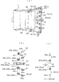
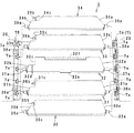
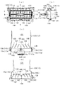
- FIG. 2B is an enlarged view of a main part showing the relationship between the fin of FIG. 2A, the link mechanism, and the switch, and FIG. It is a side view which shows four links currently performed.
- 3A is a schematic cross-sectional view taken along the line A1-A1 of FIG. 3B
- FIG. 3B is an enlarged view of the main part showing the relationship between the fins of FIG. 3A, the link mechanism, and the switch
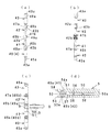
- FIG. It is a side view which shows four links which are present.
- FIG. 6 is a schematic view of the wind direction adjusting device as viewed from the direction of arrow C in FIG. 5B (and the alternate long and short dash line fins 30, 31, 33, and 34 are viewed from the direction of arrow C1 in FIG.
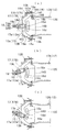
- FIG. 10 shows the wind direction adjusting device of FIG. 10 in a parallel air blowing mode state, where (a) is a front view, (b) is a schematic cross-sectional view along line AA in (a), and (c) and (d) are B in (a).
- FIG. 10 shows the wind direction adjusting device of FIG. 10 in a diffused air blowing mode state, where (a) is a front view, (b) is a schematic cross-sectional view along line AA in (a), and (c) and (d) are B in (a).
- -B line schematic cross-sectional view and CC line schematic cross-sectional view. 10 shows the wind direction adjusting device of FIG.
- FIG. 10 in an inclined air blowing mode state, where (a) is a front view, (b) is a schematic cross-sectional view along the line AA of (a), and (c) and (d) are B of (a). -B line schematic cross-sectional view and CC line schematic cross-sectional view.
- (A) is an enlarged view of FIG.13 (b), (b) and (c) are typical sectional drawings which show the state which rotated the horizontal fin in the different direction via the knob from the state of (a).
- (A) And (b) is a figure which shows the structure disclosed in FIG.1 and FIG.2 of patent document 1.
- Embodiment 1 and Embodiment 2 of the present invention will be described with reference to the accompanying drawings.
- the main operation will be referred to.
- the configuration excluding the essential part of the invention is omitted or simplified.
- the wind direction adjusting device 1 of Embodiment 1 includes a case 2 set to blow out air from the inside, and a front side in the case 2.
- One end side in the plate width direction which is disposed substantially parallel to the left and right bearing brackets 7A, 7B (7) in the vicinity of the opening and is located on the left and right sides 30a to 34a and 30b to 34b (see FIG. 8).
- the case 2 is arranged substantially parallel to the bearing brackets 9A and 9B (9) facing the upper and lower sides on the back side of the front opening, and is pivotally supported on both upper and lower side surfaces so as to be able to rotate substantially in the middle.
- a plurality of (5 in this example) vertical fins 6A to 6E (6 When, and a connecting member 9C (see Fig. 4) and operating the operating member 8 for interlocking the fins 6A ⁇ 6E.
- the vertical fin 6 can be adjusted and switched by rotating the fins 6A to 6E by a predetermined angle to the left and right via the operation member 8.
- a parallel air blowing mode in which the fins 30 to 34 are substantially parallel to each other, two or more fins (in this example, the fins 31 and 33 which are the first fins, and the fins 30 and 34 which are the second fins).
- the diffusion fan mode in which the fins 3 and 3 are configured as fins 31 and 33, which are the first fins, is rotated in opposite directions, and can be adjusted and switched via the switch 5. .
- the main part is that the switch 5 is movably assembled to the intermediate fin 32 arranged in the middle of the plurality of fins 3, and the link mechanism 4 is arranged on both sides of the intermediate fin 32.
- One end 42a, 41a side (refer to FIG. 9B) corresponding to the other end side of the first fins 31, 33 in the plate width direction is rotatably connected, and the corresponding other end 42b, 41b side. (Refer to FIG. 9 (a)) is provided with two first links 41 and 42 that are rotatably connected to the switch 5, respectively, and a plurality of fins 3 of the first fins 31 and 33.
- the second fins 30, 34 arranged on the opposite side of the intermediate fin 32, and the two second links for synchronizing or synchronizing the fin 30 with the first fin 31 and the fin 34 with the first fin 33. 40, 43 It lies in the fact you are. In the following description, since the structure other than the main part can be changed, it will be briefly described.
- the connecting members 9C are all resin products, but other than resins may be used.
- the case 2 has an inner space 24 with a front frame 25 as a decorative frame attached to the front side of the main body 20. Is formed.
- the main body 20 has engaging portions 21a and 21b provided on the rear side, positioning portions 22a and 22b provided on the front and rear portions, an attachment portion 23, and the like on the outer surface. It is attached to the installation part.
- the inner space 24 is opened in the front-rear direction, and the front frame 25 side is set as an air outlet and the rear end side is set as an air inlet.
- the front frame 25 has a flange portion 26 integrated around the frame, and is attached to the main body 20 via an engagement hole 27, engagement piece portions 28a and 28b provided in the flange portion 26, and the like. .
- each of the fins 6A to 6E has a shaft portion 6a projecting from the upper and lower ends, and is supported rotatably with respect to the brackets 9A and 9B in a state where each shaft portion 6a is fitted in the corresponding shaft hole 9a. Is done.
- Each of the fins 6A to 6E has a shaft portion 6b provided at a step portion on the upper end side and arranged one step below the shaft portion 6a.
- the shaft portion 6b is provided on an arm-shaped connecting member 9C.
- the shaft holes 9b are respectively fitted to the corresponding shaft holes 9b so as to be rotatable.
- each of the fins 6A to 6E has a base 8B attached to the operation member 8, that is, the intermediate fin 6C, and a knob 8A connected to the base 8B in a state of being slidably assembled to the intermediate fin 32 described later. When it is moved to the right and left via the connecting member 9C, everything is integrally linked via the connecting member 9C.
- the brackets 7A and 7B are formed with five shaft holes 7a facing each other as shown in FIG. 4, FIG. 7 and FIG.
- the fins 30 to 34 have shaft portions 35a to 39a protruding from the side surfaces of the right end portions 30a to 34a and the left end portions 30b to 34b, respectively, and these shaft portions 35a to 39a correspond to the brackets 7A and 7B.
- the bracket In a state of being fitted into the shaft hole 7a, the bracket is disposed substantially in parallel between the brackets and is rotatably supported.
- the fins 30 to 34 have notches 30c to 34c provided at the left end portions 30b to 34b.
- the cutout portions 30c to 34c the cutout portions 30c and 31c and the cutout portions 33c and 34c are substantially parallel to the shaft portions 35a and 36a and the shaft portions 38a and 39a and slightly smaller shaft portions 35b and 36b and shaft portions 38b and 39b. Is provided.
- the notch portion 32c of the intermediate fin 32 is formed larger than the notch portions 30c, 31c, 33c, and 34c, and the shaft portion corresponding to the shaft portions 35b, 36b, 38b, and 39b is not provided. That is, the notch 32c is a place where the corresponding end portions 41b and 42b of the first links 41 and 42 described later (and the connecting portion 51 of the switch 5 connected to the end portions 41b and 42b) are movably disposed. Used.
- the intermediate fin 32 connects the recess 32 d provided in the peripheral portion corresponding to the notch 32 c in the left end portion 32 b and the shaft portions 37 a on both sides in the left and right intermediate portions.
- the guide groove 32e is provided on one side close to the line, and the guide groove 32f is provided on the other side and faces the guide groove 32.
- the concave portion 32d constitutes a guide means when the switch 5 (described later) slides in the front-rear direction by fitting with the protrusion 56 (see FIG. 9D) on the switch 5 side.
- the guide grooves 32e and 32f are used for assembling the knob 8A of FIG. 4 so as to be slidable by a predetermined distance in the left-right direction.
- the knob 8A is coupled to the above-described base 8B in a state where it is assembled to the intermediate fin 32 via the guide grooves 32e and 32f.
- the link mechanism 4 has a total of four links, that is, the first links 41 and 42 and the second links 40 and 43 as shown in FIGS. 5A to 5C and FIGS. 9A to 9D. ing. However, as for the link mechanism 4, the second link 40, 43 is omitted if the device structure is a configuration of three fins 31 to 33 with respect to the embodiment. One link will be added.
- the lowermost link 40 is the first link, and a shaft hole 45a provided in one end 40a and a shaft hole provided in the stepped portion of the other end 40b. 45b.
- the link 41 is a second link, and includes a shaft hole 46a provided in the one end 41a and communicating with the shaft hole 45b, and a shaft portion 49b provided in the step portion of the other end 41b.
- the link 42 is a third link, and includes a shaft hole 47a provided in the one end portion 42a, and a shaft portion 49a provided in a stepped portion of the other end portion 42b and arranged back to back with the shaft portion 49b.
- the uppermost link 43 is the fourth link, and has a shaft hole 48a provided in the one end portion 43a and a shaft hole 48b provided in the step portion of the other end portion 41b and communicating with the shaft hole 47a. is doing.
- the first links 41 and 42 can rotate the shaft portion 36b of the fin 31 constituting the first fin in the shaft hole 46a.
- the other end portions 41b and 42b are connected to the connecting portion 51 of the switch 5 described later.
- the fins 31 and 33 can be adjusted and switched via the switch 5 between a parallel air blowing mode arranged substantially parallel to the intermediate fin 32 and a diffuse air blowing mode rotated in the opposite direction.
- the shaft portion 36b of the fin 31 constituting the first fin is rotatably fitted in the shaft holes 45a and 46a.
- the shaft portion 38b of the fin 33 constituting the first fin is rotatably fitted in the shaft holes 48b and 47a, and the shaft portion 35b of the fin 30 constituting the second fin is further fitted into the shaft hole.
- the shaft portion 39b of the fin 34 constituting the second fin is rotatably fitted in the shaft hole 48a. Accordingly, the fins 30 and 31 and the fins 33 and 34 can be adjusted and switched via the switch 5 between a parallel air blowing mode arranged substantially parallel to the intermediate fin 32 and a diffusion air blowing mode rotated in the opposite direction. It becomes.
- the above switch 5 is substantially U-shaped as shown in FIGS. 4, 5A to 5C, and FIGS. 9A to 9D, and the left end portion 32b of the intermediate fin 32 is disposed inside. It consists of a main body 50 and a connecting portion 51 integrated on the front side of the main body 50. Among these, the main body 50 has convex portions 56 that are respectively provided on U-shaped opposed inner surfaces and fit into the concave portions 32 d of the intermediate fins 32. The convex portion 56 constitutes a guide means for moving the switch 5 back and forth with the concave portion 32d.
- the connecting portion 51 forms link sandwiching pieces 53 and 54 that are divided into two via a longitudinal groove 52 in the middle of the left and right.
- Each pinching piece 53, 54 is provided with a lateral axial hole 53a, 54a on a coaxial line.
- the corresponding shaft portions 49a and 49b are fitted in the shaft holes 53a and 54a in a state where the links 41 and 42 overlap the other ends 41b and 42b.
- the first fins 31 and 33 are connected to each other via the switch 5 by the first links 41 and 42 (the second link 41 and the third link 42). It is possible to switch between the parallel blowing mode (c) and the diffusion blowing mode shown in FIGS. 6 (a) to 6 (c).
- FIGS. 1 (a), 2 (a) and 2 (b), and FIGS. 5 (a) to 5 (c) are states of a parallel air blowing mode in which the fins 30 to 34 are substantially parallel to each other.
- the links 40 to 43 are arranged in a straight line, and the switch 5 is moved in a direction protruding outward.
- the switch 5 in the parallel air blowing mode, the switch 5 is set to be smaller than the protruding amount of the knob 8A in consideration of safety.
- FIG. 1 (b), FIG. 3 (a), (b) and FIG. 6 (a) to (c) show that the switch 5 is maximum in the direction of the arrow in FIG.
- the fins 30 and 31 and the fins 33 and 34 are in the diffused air blowing mode in which they are pushed in the opposite directions.
- the first links 41 and 42 that are operatively connected to the switch 5 by fitting the shaft holes 54a and 53a and the shaft portions 49a and 49b are shown in the middle of FIG.
- the second links 40 and 43 that are horizontally moved in the direction, that is, rearward and operatively connected to the links 41 or 42 are vertically moved in the directions of the arrows drawn on the upper and lower sides of FIG.
- the rotation angles of the fins 30 and 31 and the fins 33 and 34 are in proportion to the movement amount of the switch 5, and various diffused air blowing modes are obtained.
- the shape of the convex portion 56 of the above-described switch is gradually lowered from the connecting portion 51 side toward the rear end portion 50a, or the convex portion 56 is formed.
- the switch 5 is located at the initial position in FIGS. 5 (a) to 5 (c) and in the pushed-in position after the movement in FIGS. 6 (a) to 6 (c). It is devised so that it does not rattle against 32. However, these can be omitted or changed.
- the switch 5 since the switch 5 is assembled so as to be movable back and forth in the plate width direction of the intermediate fin 32, the switch itself is flat and easy to make compact, and the space for arranging the switch 5 is minimized. Can be suppressed. Moreover, it is also excellent in that it is easy to add simple guide means such as irregularities 32d and 56 between the switch 5 and the intermediate fin 32 described above.
- the intermediate fin 32 has a relatively large cutout portion 32c in which the corresponding end portions 41b and 42b of the first links 41 and 42 are movably disposed.
- the connecting portion 51 between the other ends 41b, 42b of the one link 41, 42 and the switch 5 is placed in the notch 32c in the state shown in FIG. To the limit.
- the wind direction adjusting device 10 of the embodiment 2 includes a case 12 set to blow air from the inside to the outside, and a front opening in the case 12 and the vicinity thereof.
- Horizontal fins 13 pivotally supported with respect to bearing brackets 17A and 17B (17) facing left and right, and bearing brackets 19A facing the upper and lower sides of the front opening in the case 12
- a mechanism 14 and an operation knob 18 are provided.
- the horizontal fin 13 can be adjusted and switched by rotating the rear side up and down by a predetermined angle with the front side of the plate width as a fulcrum as shown in FIGS. 15 (a) to 15 (c).
- a parallel air blowing mode see FIGS. 12 (a) to (d)
- the fin 16A, which are the third fins which are the third fins.
- the diffused air blowing mode see FIGS.
- the main part is supported by the horizontal fin 13 and is movable forward and backward and left and right while being connected to the intermediate fin 16D among the vertical fins 16.
- two first links 14B and 14C in which the link mechanism 14 rotatably connects the intermediate fin 16D and the first fins 16C and 16E disposed on both sides of the intermediate fin 16D, respectively.
- the second fins 16B and 16F disposed on the opposite side of the intermediate fin 16D and the third fins 16A and 16F disposed outside the second fins 16B and 16F.
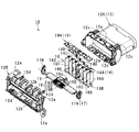
- the main body 12A and the front frame 12B constituting the case 12, the horizontal fin 13, the fins 16A to 16G constituting the vertical fin 16, and the links 14A to 14A constituting the link mechanism 14.
- 14D the upper knob 18A and the lower knob 18B constituting the knob 18, the left and right brackets 17A and 17B (17) as the support portions, and the upper and lower brackets 19A and 19B (19) as the second support portions. All are resin products, but other resins are acceptable.
- the case 12 defines an inner space 12C by a substantially cylindrical main body 12A and a front frame 12B which is a decorative frame attached to the front side of the main body 12A.
- the main body 12A and the front frame 12B are positioned by engaging the front frame side piece 12b with the main body side receiving part 12a, and the front frame side connecting piece 12d is connected to the main body side locking part 12c.
- the case 12 becomes an integral body.
- the case 12 is attached to an installation part such as a vehicle using an attachment part 12e provided on the front frame 12B.
- the inner space 12C is opened in the front-rear direction, and the front frame 12B side is set as an air outlet and the rear end side is set as an air inlet.
- horizontal fin brackets 17A and 17B are mounted on the left and right inner surfaces of the main body, and vertical fin brackets 19A and 19B are mounted on the upper and lower inner surfaces of the main body.
- the brackets 17A, 17B are respectively provided with a shaft hole 17a on the front side (side for blowing air outward) and a circular groove 17b on the rear side (back side of the inner space) (see FIG. 11).
- the arc groove 17b has a loose arc shape with the shaft hole 17 as the center.
- seven shaft holes 19a to 19g are formed in the brackets 19A and 19B so as to face each other vertically.
- the shaft holes 19a to 19b are provided at substantially equal intervals.
- the shaft holes 19a to 19c and the shaft holes 19e to 19g are simple through holes.
- the intermediate shaft hole 19d is formed in a substantially concave groove shape, that is, a dovetail shape capable of moving a shaft portion 16a of an intermediate fin 16D described later in the bracket plate width direction.
- the fins 16A to 16G are provided with a shaft 16a projecting on the same axis in the middle of the plate width direction on the upper and lower end surfaces, and a lower step on the rear surface on the upper end surface that does not project the shaft 16a. And a shaft portion 16b that protrudes from the step.
- the upper and lower shaft portions 16a of the fins 16A to 16C and 16E to 16G are formed in a simple convex shape.
- the upper and lower shaft portions 16a of the intermediate fin 16D have small necks that can move along the dovetail shape of the shaft hole 19d.
- the fins 16A to 16C and 16E to 16G are rotatably supported in a state where the upper and lower shaft portions 16a are fitted in the corresponding circular shaft holes 19a to 19g of the brackets 19A and 19B.
- the intermediate fin 16D the upper and lower shaft portions 16a are supported by the dovetail-shaped shaft holes 19d of the brackets 19A and 19B so as to be rotatable and movable back and forth.
- the fins 16A to 16G are operatively connected by four links 14A to 14D constituting the link mechanism 14.
- the intermediate fin 16D located in the middle of the left and right and the first fins 16C and 16E arranged on both sides of the intermediate fin 16D are rotatably connected by two first links 14B and 14C.
- One first fin 16C and the second fin 16B outside the first fin 16C and the third fin 16A outside the second fin 16B are rotatably connected by the second link 14A.
- the other first fin 16E and the second fin 16F outside the first fin 16E and the third fin 16G outside the second fin 16F are rotatably connected by a second link 14D.
- the intermediate fan 16D has a circular groove 16d on the front side in the plate width direction and provided in the vertical direction, and a piece 16c that can be gripped between the circular groove 16d and the front edge portion.
- the front edges of the first fins 16C and 16E and the piece 16c are formed in an arc shape.
- first links 14B and 14C have shaft holes 14a and 14a provided on both ends.
- One of the first links 14B has one end-side shaft hole 14a fitted with the shaft portion 16b of the first fin 16C, and the other end-side shaft hole 14a fitted with the shaft portion 16b of the intermediate fin 16D. Yes.
- the shaft hole 14a on one end side is fitted to the shaft portion 16b of the intermediate fin 16D, and the shaft hole 14a on the other end side is fitted to the shaft portion 16b of the first fin 16E.
- 2nd link 14A, 14D is longer than 1st link 14B, 14C, and has the three axial holes 14a provided in the both ends side and the middle, respectively.
- one end side shaft hole 14a is fitted to the shaft portion 16b of the third fin 16A, and the other end side shaft hole 14a is fitted to the shaft portion 16b of the first fin 16C.
- the intermediate shaft hole 14a is fitted to the shaft portion 16b of the second fin 16B.
- the shaft hole 14a on one end side is fitted with the shaft portion 16b of the third fin 16G, and the shaft hole 14a on the other end side is fitted on the shaft portion 16b of the first fin 16E.
- the shaft hole 14a is engaged with the shaft portion 16b of the second fin 16F.
- the above-described horizontal fin 13 is rotatably supported between the brackets 17A and 17B. That is, the horizontal fin 13 includes the shaft portion 13a and the shaft portion 13b projecting from the left and right side surfaces respectively, and the relief opening 13c and the opening 13c provided at the rear side at the left and right intermediate portions. Including the restricting portion 13d that is formed with a one-tier thickness on the front side, and a hole portion 13e provided in the middle of the restricting portion 13d.
- the horizontal fin 13 is disposed substantially parallel between the brackets 17A and 17B with the shaft portions 13a on both sides fitted in the corresponding shaft holes 17a, and the shaft portions on both sides. 13b is fitted in the arcuate guide hole 17b.
- the horizontal fin 13 is supported so that the rear side in the plate width direction can be turned up and down by a predetermined angle according to the arc-shaped guide hole 17b with the shaft portion 13a as a fulcrum.
- An elastic body (not shown) is attached to the hole 13e as necessary.
- the elastic body is a member that prevents the knob 18 from being inadvertently displaced due to vibration or the like by appropriately pressing against an operation knob 18 described later.
- the knob 18 is assembled to the horizontal fin 13 so that the knob 18 can be moved back and forth by a predetermined dimension and can be moved laterally by a predetermined dimension at the foremost position.
- the knob 18 includes an upper knob 18A and a lower knob 18B that sandwich the fin 13 from above and below, and a decorative knob 18C that is mounted between the knobs 18A and 18B and is mounted on the front side.
- the upper and lower knobs 18A and 18B include a substantially L-shaped piece 18a projecting in the middle of the left and right of the rear edge, and a step 18b that is provided on the opposing inner surface to escape the restricting portion 13d and restrict the movement range of the knob 18.
- the above knob 18 is attached, for example, with the decorative knob 18C engaging both ends of the retaining wall 18c with the lower knob 18B. Thereafter, when the upper and lower knobs 18A and 18B are stacked so as to sandwich the fin 13 from above and below, the lower knob side claw portion 18e and the engaging portion 18f are respectively engaged with the corresponding portions of the upper knob 18A. .
- this knob is assembled, as shown in FIG. 12C, each piece 18a of the upper and lower knobs is disposed in the arc groove 16d of the intermediate fin 16D. For this reason, the knob 18 constrains the piece 16c of the intermediate fin 16D inside each piece 18a in a state where the upper and lower knobs 18A and 18B are integrated, and is connected or linked to the intermediate fin 16D according to the restriction mode. ing.
- FIGS. 12 (a) to 12 (d) and FIGS. 15 (a) to 15 (c) show the state of the parallel air blowing mode in which the fins 16A to 16G are substantially parallel to the bracket 17 and substantially parallel to each other. It is. In this state, the links 14A to 14D are arranged linearly, and the knob 18 is arranged substantially in the middle of the horizontal fin 13 on the left and right. In other words, in the parallel air blowing mode, the knob 18 is located at the normal position of FIGS. 12A to 12D with respect to the horizontal fin 13, that is, at the intermediate portion where the stepped portion 18b is elongated in the lateral direction. It is in the state where the horizontal part is located.
- the knob 18 is pulled to the maximum in the direction of the arrow in FIG. 13B from the state of the parallel air blowing mode, so that the fins 16A to 16C and the fins 16E to 16G It is the state of the diffuse ventilation mode rotated in the opposite direction.
- the knob 18 is regulated at the forefront position in FIG. 13B, which is the front side from the normal position in FIGS. 12A to 12D with respect to the horizontal fin 13, that is, the rear end surface of the step portion 18b.
- the intermediate fin 16D is pulled by the knob 18 and moved forward along the dovetail shape of the shaft hole 19d.
- the intermediate fin 16D moves forward, the intermediate fin 16D maintains a state substantially parallel to the bracket 17, and the piece 16c or the front side enters the opening 13c and is released.
- the other fins 16A to 16C are spread through the first link 14B and the second link 14A, and the fins 16E to 16G are spread through the first link 14C and the second link 14E, respectively, in the opposite directions.
- Switch to blower mode Of course, the rotation angles of the fins 16A to 16C and the fins 16E to 16G are proportional to the pulling amount of the knob 18, and various diffused air blowing modes are obtained.
- FIGS. 14A to 14D show that the knob 18 is laterally moved to the maximum in the direction of the arrow in FIG. And a state of an inclined air blowing mode that is rotated in substantially the same direction and inclined.
- the knob 18 in the state of the parallel air blowing mode that is the normal position, the knob 18 is in the lateral direction right or left side, that is, until the end surface of the portion extending to the left and right of the stepped portion 18b hits the front corresponding end surface of the restricting portion 13d.
- the intermediate fin 16 ⁇ / b> D is rotated in a direction corresponding to the moving direction of the knob 18 with the upper and lower shaft portions 16 b as fulcrums, and is in an inclined state that is not parallel to the bracket 17.
- each fin 16A to 16G rotates in the same direction as the fin 16D through the first link 14B and the second link 14A
- the fins 16E to 16G rotate in the same direction as the fin 16D through the first link 14C and the second link 14E, respectively.
- This inclined air blowing mode is sometimes referred to as a swing air blowing mode because each fin 16A to 16G has an angle corresponding to the degree of lateral movement of the knob 18 or the degree of rotation of each fin 16.
- FIG. 15B shows a state in which the fin 13 is pushed downward as indicated by the arrow in FIG.
- the fin 13 is rotated counterclockwise with the shaft portion 13a as a fulcrum until the shaft portion 13b abuts against the bracket 17 on both sides and the shaft portion 13b hits the inner upper end of the arc groove 17b. It is in an upwardly inclined state.
- 15C shows a state in which the fin 13 is pushed downward, which is the arrow direction in FIG.
- the fin 13 is rotated clockwise with the shaft portion 13a as a fulcrum until the shaft portion 13b abuts against the bracket 17 on both sides and the shaft portion 13b hits the inner bottom end of the arc groove 17b and is regulated.
- the state is inclined downward.
- the fin 13 is lightly applied to an arcuate curved surface provided on the front edge side of the first fins 16C and 16E and the intermediate fin 16D (a part 16c thereof) in both the upward inclined state and the downward inclined state. Since the state is maintained by touching, it is returned to the horizontal state of FIG.
- the wind direction adjusting device of this invention should just be provided with the structure specified by an independent claim, and a detail can be changed and developed with reference to the above description.
- a configuration in which the front frame is retrofitted to the main body has been shown as the case, but the front frame is abolished, and the main body shape and front frame shape are also arbitrary.
- the vertical fins can be omitted, and in the second embodiment, the horizontal fins can be made non-movable.
Landscapes
- Engineering & Computer Science (AREA)
- Mechanical Engineering (AREA)
- Physics & Mathematics (AREA)
- Thermal Sciences (AREA)
- Chemical & Material Sciences (AREA)
- Combustion & Propulsion (AREA)
- General Engineering & Computer Science (AREA)
- Air-Flow Control Members (AREA)
- Air-Conditioning For Vehicles (AREA)
Abstract
Description
(1)本発明の第1観点による風向調整装置において、前記複数のフィンは前記第1フィンの両隣のうち、前記中間フィンと反対側に配置された第2フィンを有していると共に、前記リンク機構は前記第2フィンの板幅方向の他端側と前記第1フィンの板幅方向の他端側に異なる端部をそれぞれ回動自在に連結している2つの第2リンクを有している構成である。この好ましい態様によれば、フィンが形態例のごとく少なくとも5枚であり、その場合は更に2つのリンクを追加すればよいため合計5つの部材にて実施できる。加えて、特許文献1のようなケース内をばねの付勢力に抗して移動する部材やラッチ機構なども不要となるため、簡易構成それによる良好な作動を実現でき、軽量化も図り易いものとなる。
(2)本発明の第1観点による風向調整装置において、前記スイッチは、押し操作により前記中間フィンの板幅方向である後方移動して前記第1フィン、又は、前記第1フィン及び第2フィンを前記リンク機構を介して平行送風モードから拡散送風モードに切り換える構成である。この好ましい態様によれば、スイッチを中間フィンの板幅方向に前後動可能に組み付けるため、スイッチ自体をコンパクト化し易く、更にスイッチ用配置空間を最小限に抑えることができる。
(4)上記(1)乃至(3)の好ましい態様において、前記第1フィン及び前記第2フィンは前記第1リンクや前記第2リンクに設けられた軸孔に嵌合する軸部を形成していると共に、前記中間フィンは前記軸部に代えて前記第1リンクの対応する端部を移動可能に配置する切欠部を形成している構成である。この好ましい態様によれば、例えば、第1リンクの他端とスイッチとの連結部を中間フィンの切欠部に配した状態で水平送風モードとすることで連結部用の配置空間を最小限に抑えることができる。
(6)上記(5)の好ましい態様において、前記ケース内の対向した第2支持部に対し左右の両端側が回動可能に枢支された横型フィンを有し、前記ノブは前記横型フィンに対し前後及び左右に移動可能に支持されており、前方移動操作により前記第1フィン、又は、前記第1フィン及び前記第2フィン、又は、前記第1フィンから前記第3フィンを前記リンク機構を介して平行送風モードから拡散送風モードに切り換える構成である。この好ましい態様によれば、ノブが横型フィンに対し前後及び左右に移動可能に支持されているためノブの支持構造を簡略化でき、横型フィンを回動可能に支持するだけで横型フィンの姿勢に応じて更に送風態様を変化可能となる。
(7)上記(5)又は(6)の好ましい態様において、前記ノブは、前記前方移動した状態にて、後方への押し操作により前記第1フィン、又は、前記第1フィン及び前記第2フィン、又は、前記第1フィンから前記第3フィンを前記リンク機構を介して拡散送風モードから前記支持部と略平行となる平行送風モードに切り換えると共に、その状態にて左又は右側への移動操作により前記各フィンを略同方向へ回動して前記支持部と非平行となる傾斜送風モードに切り換える構成である。この好ましい態様によれば、平行送風モードと拡散送風モードとをノブの前後移動操作により切換可能、かつ、平行送風モードと傾斜送風モードとをノブの横移動操作により切換可能なことから、少ない部品で多様な送風モードを実現できる。
(1)、図1(a)と図2(a)(b)及び図5(a)~(c)は、各フィン30~34が互いに略平行となる平行送風モードの状態である。この状態では、各リンク40~43が直線状に配置されていると共に、スイッチ5が外側へ突出する方向へ移動されている。この構造では、平行送風モードにおいて、スイッチ5が安全性に対する配慮からノブ8Aの突出量よりも小さく設定されている。
(1)、図12(a)~(d)及び図15(a)~(c)は、各フィン16A~16Gがブラケット17に略平行となり、かつ、互いに略平行となる平行送風モードの状態である。この状態では、各リンク14A~14Dが直線状に配置されていると共に、ノブ18が横型フィン13の略左右中間に配置されている。換言すると、平行送風モードでは、ノブ18が横型フィン13に対して図12(a)~(d)の通常位置、つまり段差部18bの横方向に長くなった中間箇所に規制部13dの手間側横部分を位置した状態となっている。
2013年12月12日に出願された日本国特願2013-256623号の明細書、特許請求の範囲、図面及び要約書の全内容をここに引用し、本発明の明細書の開示として、取り入れるものである。
Claims (9)
- 空気を前側開口部より外へ吹き出すよう設定されたケースと、前記ケース内の対向した支持部に対し略平行に配置され、かつ左右の両側面にあって板幅方向の一端側を回動可能に枢支された複数のフィンと、前記フィンの2以上を連動させるリンク機構及び前記リンク機構に連携されたスイッチとを備え、前記フィンが互いに略平行となる平行送風モードと、前記フィンの2以上を互いに反対方向に回動した拡散送風モードとを前記スイッチを介して調整切換可能な風向調整装置であって、
前記スイッチは前記複数のフィンのうち中間に配置された中間フィンに移動可能に組み付けられると共に、前記リンク機構は前記中間フィンの両隣に配されている第1フィンの板幅方向の他端側に対応する一端側をそれぞれ回動自在に連結し、かつ対応する他端側を前記スイッチにそれぞれ回動自在に連結している2つの第1リンクを有していることを特徴とする風向調整装置。 - 空気を前側開口部より外へ吹き出すよう設定されたケースと、前記ケース内の対向した支持部に対し上下の両端側を回動可能に枢支された複数のフィンと、前記フィンの2以上を連動させるリンク機構及び操作用ノブとを備え、前記フィンが互いに略平行となる平行送風モードと、前記フィンの2以上を互いに反対方向に回動した拡散送風モードとを前記ノブを介して調整切換可能な風向調整装置であって、
前記ノブは前記複数のフィンのうち中間に配置された中間フィンに連結された状態で前後及び左右に移動可能に支持されると共に、前記リンク機構は前記中間フィンの両隣に配されている第1フィンに対応する一端側をそれぞれ回動自在に連結し、かつ対応する他端側を前記中間フィンにそれぞれ回動自在に連結している2つの第1リンクを有していることを特徴とする風向調整装置。 - 前記複数のフィンは前記第1フィンの両隣のうち、前記中間フィンと反対側に配置された第2フィンを有していると共に、前記リンク機構は前記第2フィンの板幅方向の他端側と前記第1フィンの板幅方向の他端側に異なる端部をそれぞれ回動自在に連結している2つの第2リンクを有していることを特徴とする請求項1に記載の風向調整装置。
- 前記スイッチは、押し操作により前記中間フィンの板幅方向である後方移動して前記第1フィン、又は、前記第1フィン及び第2フィンを前記リンク機構を介して平行送風モードから拡散送風モードに切り換えることを特徴とする請求項1又は3に記載の風向調整装置。
- 前記スイッチは、前記後方移動した状態にて、引き操作により前記中間フィンの板幅方向である前方移動することで、或いは、前記第1フィン又は前記第2フィンを直に回動することでも拡散送風モードから平行送風モードに切換可能であることを特徴とする請求項4に記載の風向調整装置。
- 前記第1フィン及び前記第2フィンは前記第1リンクや前記第2リンクに設けられた軸孔に嵌合する軸部を形成していると共に、前記中間フィンは前記軸部に代えて前記第1リンクの対応する端部を移動可能に配置する切欠部を形成していることを特徴とする請求項3から5の何れか1に記載の風向調整装置。
- 前記複数のフィンは前記第1フィンの両隣のうち、前記中間フィンと反対側に配置された第2フィンと、前記第2フィンの両隣のうち、前記第1フィンと反対側に配置された第3フィンとを有し、
前記リンク機構は前記第1フィンと、前記第2フィンと、前記第3フィンとをそれぞれ回動自在に連結している2つの第2リンクを有していることを特徴とする請求項2に記載の風向調整装置。 - 前記ケース内の対向した第2支持部に対し左右の両端側が回動可能に枢支された横型フィンを有し、前記ノブは前記横型フィンに対し前後及び左右に移動可能に支持されており、前方移動操作により前記第1フィン、又は、前記第1フィン及び前記第2フィン、又は、前記第1フィンから前記第3フィンを前記リンク機構を介して平行送風モードから拡散送風モードに切り換えることを特徴とする請求項7に記載の風向調整装置。
- 前記ノブは、前記前方移動した状態にて、後方への押し操作により前記第1フィン、又は、前記第1フィン及び前記第2フィン、又は、前記第1フィンから前記第3フィンを前記リンク機構を介して拡散送風モードから前記支持部と略平行となる平行送風モードに切り換えると共に、その状態にて左又は右側への移動操作により前記各フィンを略同方向へ回動して前記支持部と非平行となる傾斜送風モードに切り換えることを特徴とする請求項7又は8に記載の風向調整装置。
Priority Applications (5)
| Application Number | Priority Date | Filing Date | Title |
|---|---|---|---|
| KR1020167017338A KR101928633B1 (ko) | 2013-12-12 | 2014-12-11 | 풍향조정장치 |
| US15/104,058 US10254004B2 (en) | 2013-12-12 | 2014-12-11 | Airflow-direction adjustment device |
| EP14870499.2A EP3081412B1 (en) | 2013-12-12 | 2014-12-11 | Airflow direction adjustment device |
| CN201480067337.2A CN105813872B (zh) | 2013-12-12 | 2014-12-11 | 风向调节装置 |
| JP2015552514A JP6120992B2 (ja) | 2013-12-12 | 2014-12-11 | 風向調整装置 |
Applications Claiming Priority (2)
| Application Number | Priority Date | Filing Date | Title |
|---|---|---|---|
| JP2013256623 | 2013-12-12 | ||
| JP2013-256623 | 2013-12-12 |
Publications (1)
| Publication Number | Publication Date |
|---|---|
| WO2015087975A1 true WO2015087975A1 (ja) | 2015-06-18 |
Family
ID=53371274
Family Applications (1)
| Application Number | Title | Priority Date | Filing Date |
|---|---|---|---|
| PCT/JP2014/082863 Ceased WO2015087975A1 (ja) | 2013-12-12 | 2014-12-11 | 風向調整装置 |
Country Status (6)
| Country | Link |
|---|---|
| US (1) | US10254004B2 (ja) |
| EP (1) | EP3081412B1 (ja) |
| JP (1) | JP6120992B2 (ja) |
| KR (2) | KR20150068900A (ja) |
| CN (1) | CN105813872B (ja) |
| WO (1) | WO2015087975A1 (ja) |
Cited By (6)
| Publication number | Priority date | Publication date | Assignee | Title |
|---|---|---|---|---|
| JP2017088088A (ja) * | 2015-11-16 | 2017-05-25 | 豊田合成株式会社 | 空調用レジスタ |
| JP2017100467A (ja) * | 2015-11-30 | 2017-06-08 | 株式会社ニフコ | 風向調整装置 |
| CN107009850A (zh) * | 2015-12-30 | 2017-08-04 | 佛吉亚内部空间系统有限公司 | 出口设备 |
| WO2018088399A1 (ja) * | 2016-11-10 | 2018-05-17 | 株式会社ニフコ | 風向調整装置 |
| CN110103676A (zh) * | 2019-04-19 | 2019-08-09 | 浙江吉利控股集团有限公司 | 一种车载空调出风调节装置及具有该调节装置的车辆 |
| WO2023124764A1 (zh) * | 2021-12-30 | 2023-07-06 | 延锋国际汽车技术有限公司 | 用于交通工具的通风口装置 |
Families Citing this family (19)
| Publication number | Priority date | Publication date | Assignee | Title |
|---|---|---|---|---|
| WO2015084100A1 (en) * | 2013-12-06 | 2015-06-11 | Nifco Korea Inc. | Structure for mounting wing knob for vehicle air vent |
| JP6260543B2 (ja) * | 2015-01-13 | 2018-01-17 | トヨタ自動車株式会社 | レジスタ |
| JP6534526B2 (ja) * | 2015-01-13 | 2019-06-26 | 豊和化成株式会社 | レジスタ用操作ノブ |
| KR101683508B1 (ko) | 2015-06-26 | 2016-12-07 | 현대자동차 주식회사 | 차량용 에어 벤트 장치 |
| KR101684192B1 (ko) * | 2015-12-10 | 2016-12-07 | 현대자동차주식회사 | 자동차용 에어벤트 |
| US10752088B2 (en) * | 2016-12-09 | 2020-08-25 | Tesla, Inc. | Infotainment system with air-vent control |
| JP2019038390A (ja) | 2017-08-25 | 2019-03-14 | 豊田合成株式会社 | 空調用レジスタ |
| KR102394803B1 (ko) * | 2017-09-25 | 2022-05-04 | 현대자동차주식회사 | 자동차용 슬림형 에어벤트 장치 |
| US10807443B2 (en) * | 2017-10-31 | 2020-10-20 | Honda Motor Co., Ltd. | Air vent for a vehicle HVAC system |
| CN107856502B (zh) * | 2017-11-09 | 2019-12-31 | 安徽江淮汽车集团股份有限公司 | 空调出风口组件 |
| IT201800002534A1 (it) * | 2018-02-09 | 2019-08-09 | Plastic Components And Modules Automotive S P A | Diffusore di aerazione per veicoli. |
| KR102598528B1 (ko) * | 2018-05-16 | 2023-11-03 | 현대자동차주식회사 | 자동차용 전동식 에어벤트 장치 |
| KR102359587B1 (ko) * | 2019-04-04 | 2022-02-07 | 현대자동차주식회사 | 에어벤트 장치 |
| CN110341439B (zh) * | 2019-07-09 | 2021-03-26 | 比亚迪股份有限公司 | 一种出风口导风结构及其安装方法 |
| CN110588292A (zh) * | 2019-07-27 | 2019-12-20 | 浙江智动汽车部件有限公司 | 一种新型的出风口叶片结构 |
| CN110500756B (zh) * | 2019-09-07 | 2023-08-22 | 珠海格力电器股份有限公司 | 一种出风组件、控制方法及空调 |
| DE102020207151A1 (de) * | 2020-06-08 | 2021-12-09 | Volkswagen Aktiengesellschaft | Luftausströmer für ein Kraftfahrzeug |
| US11940171B2 (en) * | 2021-01-19 | 2024-03-26 | Air Distribution Technologies Ip, Llc | Diffuser adjustment assembly systems and methods |
| CN113212116B (zh) * | 2021-06-03 | 2022-06-14 | 宁波均胜群英汽车系统股份有限公司 | 一种联动控制的出风口 |
Citations (7)
| Publication number | Priority date | Publication date | Assignee | Title |
|---|---|---|---|---|
| JPS5754935U (ja) * | 1980-09-17 | 1982-03-31 | ||
| JPS5972440U (ja) * | 1982-11-06 | 1984-05-17 | トヨタ自動車株式会社 | 空気吹出しグリル装置 |
| JPS5991531U (ja) * | 1982-12-10 | 1984-06-21 | トヨタ自動車株式会社 | 空気吹出しグリル装置 |
| JPS60178741U (ja) * | 1984-05-07 | 1985-11-27 | 株式会社日立ホームテック | 風向切替装置 |
| JPH0387155U (ja) * | 1989-12-22 | 1991-09-04 | ||
| JPH0461247U (ja) * | 1990-10-01 | 1992-05-26 | ||
| JP2002277040A (ja) | 2001-01-16 | 2002-09-25 | Trw Automot Electronics & Components Gmbh & Co Kg | 空気ベント、特に車輛空調用空気ベント |
Family Cites Families (7)
| Publication number | Priority date | Publication date | Assignee | Title |
|---|---|---|---|---|
| US5364303A (en) * | 1993-07-09 | 1994-11-15 | Summit Polymers, Inc. | Air vent adjustable vanes for controlling air flow direction |
| FR2710879B1 (fr) | 1993-10-06 | 1996-01-05 | Peugeot | Aérateur perfectionné, notamment pour planche de bord de véhicule automobile. |
| US5690550A (en) | 1996-04-24 | 1997-11-25 | Manchester Plastics, Inc. | Diffuser outlet assembly |
| JP4379188B2 (ja) * | 2004-04-22 | 2009-12-09 | 豊田合成株式会社 | 空調用レジスタ |
| JP4890203B2 (ja) * | 2006-11-20 | 2012-03-07 | 豊和化成株式会社 | 車室内用空気吹出装置 |
| JP5404713B2 (ja) * | 2011-08-11 | 2014-02-05 | 三菱電機株式会社 | 左右風向調整装置およびこれを装備した空気調和機の室内機 |
| DE102011115178B4 (de) | 2011-09-28 | 2014-10-09 | Audi Ag | Luftausströmer eines Lüftungs- und Heizungsmoduls für Kraftfahrzeuge mit einer Umschaltung zwischen einer Spotstellung und einer Diffusstellung |
-
2014
- 2014-11-26 KR KR1020140166098A patent/KR20150068900A/ko not_active Ceased
- 2014-12-11 EP EP14870499.2A patent/EP3081412B1/en active Active
- 2014-12-11 CN CN201480067337.2A patent/CN105813872B/zh active Active
- 2014-12-11 JP JP2015552514A patent/JP6120992B2/ja active Active
- 2014-12-11 KR KR1020167017338A patent/KR101928633B1/ko active Active
- 2014-12-11 WO PCT/JP2014/082863 patent/WO2015087975A1/ja not_active Ceased
- 2014-12-11 US US15/104,058 patent/US10254004B2/en active Active
Patent Citations (7)
| Publication number | Priority date | Publication date | Assignee | Title |
|---|---|---|---|---|
| JPS5754935U (ja) * | 1980-09-17 | 1982-03-31 | ||
| JPS5972440U (ja) * | 1982-11-06 | 1984-05-17 | トヨタ自動車株式会社 | 空気吹出しグリル装置 |
| JPS5991531U (ja) * | 1982-12-10 | 1984-06-21 | トヨタ自動車株式会社 | 空気吹出しグリル装置 |
| JPS60178741U (ja) * | 1984-05-07 | 1985-11-27 | 株式会社日立ホームテック | 風向切替装置 |
| JPH0387155U (ja) * | 1989-12-22 | 1991-09-04 | ||
| JPH0461247U (ja) * | 1990-10-01 | 1992-05-26 | ||
| JP2002277040A (ja) | 2001-01-16 | 2002-09-25 | Trw Automot Electronics & Components Gmbh & Co Kg | 空気ベント、特に車輛空調用空気ベント |
Cited By (10)
| Publication number | Priority date | Publication date | Assignee | Title |
|---|---|---|---|---|
| JP2017088088A (ja) * | 2015-11-16 | 2017-05-25 | 豊田合成株式会社 | 空調用レジスタ |
| JP2017100467A (ja) * | 2015-11-30 | 2017-06-08 | 株式会社ニフコ | 風向調整装置 |
| WO2017094619A1 (ja) * | 2015-11-30 | 2017-06-08 | 株式会社ニフコ | 風向調整装置 |
| CN108290476A (zh) * | 2015-11-30 | 2018-07-17 | 株式会社利富高 | 风向调整装置 |
| CN108290476B (zh) * | 2015-11-30 | 2021-07-13 | 株式会社利富高 | 风向调整装置 |
| CN107009850A (zh) * | 2015-12-30 | 2017-08-04 | 佛吉亚内部空间系统有限公司 | 出口设备 |
| WO2018088399A1 (ja) * | 2016-11-10 | 2018-05-17 | 株式会社ニフコ | 風向調整装置 |
| JP2018075988A (ja) * | 2016-11-10 | 2018-05-17 | 株式会社ニフコ | 風向調整装置 |
| CN110103676A (zh) * | 2019-04-19 | 2019-08-09 | 浙江吉利控股集团有限公司 | 一种车载空调出风调节装置及具有该调节装置的车辆 |
| WO2023124764A1 (zh) * | 2021-12-30 | 2023-07-06 | 延锋国际汽车技术有限公司 | 用于交通工具的通风口装置 |
Also Published As
| Publication number | Publication date |
|---|---|
| KR101928633B1 (ko) | 2018-12-12 |
| JP6120992B2 (ja) | 2017-04-26 |
| EP3081412B1 (en) | 2020-07-01 |
| US20160313025A1 (en) | 2016-10-27 |
| KR20150068900A (ko) | 2015-06-22 |
| US10254004B2 (en) | 2019-04-09 |
| KR20160091415A (ko) | 2016-08-02 |
| CN105813872A (zh) | 2016-07-27 |
| EP3081412A4 (en) | 2017-11-15 |
| EP3081412A1 (en) | 2016-10-19 |
| CN105813872B (zh) | 2019-02-05 |
| JPWO2015087975A1 (ja) | 2017-03-16 |
Similar Documents
| Publication | Publication Date | Title |
|---|---|---|
| JP6120992B2 (ja) | 風向調整装置 | |
| JP5772775B2 (ja) | 空調用レジスタ | |
| JP6385007B2 (ja) | 風向調整装置 | |
| JP6536395B2 (ja) | 空調用レジスタ | |
| WO2017141839A1 (ja) | 空気調和機 | |
| JP2002277040A (ja) | 空気ベント、特に車輛空調用空気ベント | |
| JP6217556B2 (ja) | 空調用レジスタ | |
| JP5724852B2 (ja) | 空調用レジスタ | |
| JP6229631B2 (ja) | 空調用レジスタ | |
| JP2013112256A (ja) | 空調用レジスタ | |
| JP6499609B2 (ja) | 車両用レジスタ装置 | |
| JP6500235B2 (ja) | 空調用レジスタ | |
| JP6629168B2 (ja) | 風向調整装置 | |
| JP2016052815A (ja) | レジスタ | |
| JP4720871B2 (ja) | 空気調和機の室内機 | |
| JP2017177979A (ja) | レジスタ | |
| JP5028349B2 (ja) | レジスタ | |
| JP3829691B2 (ja) | 風向調整装置 | |
| JP2019130991A (ja) | 風向調整装置 | |
| JP5680478B2 (ja) | 風向調整装置 | |
| JP6958501B2 (ja) | 空調用レジスタ | |
| JP3341748B2 (ja) | 車両用ベンチレータ | |
| JP6800465B2 (ja) | 空調用レジスタ | |
| JP7119855B2 (ja) | 空調用レジスタ | |
| WO2013125025A1 (ja) | 換気装置 |
Legal Events
| Date | Code | Title | Description |
|---|---|---|---|
| 121 | Ep: the epo has been informed by wipo that ep was designated in this application |
Ref document number: 14870499 Country of ref document: EP Kind code of ref document: A1 |
|
| ENP | Entry into the national phase |
Ref document number: 2015552514 Country of ref document: JP Kind code of ref document: A |
|
| NENP | Non-entry into the national phase |
Ref country code: DE |
|
| WWE | Wipo information: entry into national phase |
Ref document number: 15104058 Country of ref document: US |
|
| REEP | Request for entry into the european phase |
Ref document number: 2014870499 Country of ref document: EP |
|
| WWE | Wipo information: entry into national phase |
Ref document number: 2014870499 Country of ref document: EP |
|
| ENP | Entry into the national phase |
Ref document number: 20167017338 Country of ref document: KR Kind code of ref document: A |