WO2015092895A1 - 空気調和装置 - Google Patents
空気調和装置 Download PDFInfo
- Publication number
- WO2015092895A1 WO2015092895A1 PCT/JP2013/084003 JP2013084003W WO2015092895A1 WO 2015092895 A1 WO2015092895 A1 WO 2015092895A1 JP 2013084003 W JP2013084003 W JP 2013084003W WO 2015092895 A1 WO2015092895 A1 WO 2015092895A1
- Authority
- WO
- WIPO (PCT)
- Prior art keywords
- temperature
- humidity
- indoor
- operation mode
- mode
- Prior art date
- Legal status (The legal status is an assumption and is not a legal conclusion. Google has not performed a legal analysis and makes no representation as to the accuracy of the status listed.)
- Ceased
Links
Images


Classifications
-
- F—MECHANICAL ENGINEERING; LIGHTING; HEATING; WEAPONS; BLASTING
- F24—HEATING; RANGES; VENTILATING
- F24F—AIR-CONDITIONING; AIR-HUMIDIFICATION; VENTILATION; USE OF AIR CURRENTS FOR SCREENING
- F24F11/00—Control or safety arrangements
- F24F11/30—Control or safety arrangements for purposes related to the operation of the system, e.g. for safety or monitoring
-
- F—MECHANICAL ENGINEERING; LIGHTING; HEATING; WEAPONS; BLASTING
- F24—HEATING; RANGES; VENTILATING
- F24F—AIR-CONDITIONING; AIR-HUMIDIFICATION; VENTILATION; USE OF AIR CURRENTS FOR SCREENING
- F24F11/00—Control or safety arrangements
- F24F11/62—Control or safety arrangements characterised by the type of control or by internal processing, e.g. using fuzzy logic, adaptive control or estimation of values
-
- F—MECHANICAL ENGINEERING; LIGHTING; HEATING; WEAPONS; BLASTING
- F24—HEATING; RANGES; VENTILATING
- F24F—AIR-CONDITIONING; AIR-HUMIDIFICATION; VENTILATION; USE OF AIR CURRENTS FOR SCREENING
- F24F11/00—Control or safety arrangements
- F24F11/62—Control or safety arrangements characterised by the type of control or by internal processing, e.g. using fuzzy logic, adaptive control or estimation of values
- F24F11/63—Electronic processing
-
- F—MECHANICAL ENGINEERING; LIGHTING; HEATING; WEAPONS; BLASTING
- F24—HEATING; RANGES; VENTILATING
- F24F—AIR-CONDITIONING; AIR-HUMIDIFICATION; VENTILATION; USE OF AIR CURRENTS FOR SCREENING
- F24F11/00—Control or safety arrangements
- F24F11/62—Control or safety arrangements characterised by the type of control or by internal processing, e.g. using fuzzy logic, adaptive control or estimation of values
- F24F11/63—Electronic processing
- F24F11/65—Electronic processing for selecting an operating mode
-
- F—MECHANICAL ENGINEERING; LIGHTING; HEATING; WEAPONS; BLASTING
- F24—HEATING; RANGES; VENTILATING
- F24F—AIR-CONDITIONING; AIR-HUMIDIFICATION; VENTILATION; USE OF AIR CURRENTS FOR SCREENING
- F24F11/00—Control or safety arrangements
- F24F11/70—Control systems characterised by their outputs; Constructional details thereof
- F24F11/72—Control systems characterised by their outputs; Constructional details thereof for controlling the supply of treated air, e.g. its pressure
- F24F11/74—Control systems characterised by their outputs; Constructional details thereof for controlling the supply of treated air, e.g. its pressure for controlling air flow rate or air velocity
- F24F11/77—Control systems characterised by their outputs; Constructional details thereof for controlling the supply of treated air, e.g. its pressure for controlling air flow rate or air velocity by controlling the speed of ventilators
-
- F—MECHANICAL ENGINEERING; LIGHTING; HEATING; WEAPONS; BLASTING
- F24—HEATING; RANGES; VENTILATING
- F24F—AIR-CONDITIONING; AIR-HUMIDIFICATION; VENTILATION; USE OF AIR CURRENTS FOR SCREENING
- F24F11/00—Control or safety arrangements
- F24F11/70—Control systems characterised by their outputs; Constructional details thereof
- F24F11/72—Control systems characterised by their outputs; Constructional details thereof for controlling the supply of treated air, e.g. its pressure
- F24F11/79—Control systems characterised by their outputs; Constructional details thereof for controlling the supply of treated air, e.g. its pressure for controlling the direction of the supplied air
-
- F—MECHANICAL ENGINEERING; LIGHTING; HEATING; WEAPONS; BLASTING
- F24—HEATING; RANGES; VENTILATING
- F24F—AIR-CONDITIONING; AIR-HUMIDIFICATION; VENTILATION; USE OF AIR CURRENTS FOR SCREENING
- F24F11/00—Control or safety arrangements
- F24F11/70—Control systems characterised by their outputs; Constructional details thereof
- F24F11/80—Control systems characterised by their outputs; Constructional details thereof for controlling the temperature of the supplied air
- F24F11/83—Control systems characterised by their outputs; Constructional details thereof for controlling the temperature of the supplied air by controlling the supply of heat-exchange fluids to heat-exchangers
-
- F—MECHANICAL ENGINEERING; LIGHTING; HEATING; WEAPONS; BLASTING
- F24—HEATING; RANGES; VENTILATING
- F24F—AIR-CONDITIONING; AIR-HUMIDIFICATION; VENTILATION; USE OF AIR CURRENTS FOR SCREENING
- F24F11/00—Control or safety arrangements
- F24F11/70—Control systems characterised by their outputs; Constructional details thereof
- F24F11/80—Control systems characterised by their outputs; Constructional details thereof for controlling the temperature of the supplied air
- F24F11/83—Control systems characterised by their outputs; Constructional details thereof for controlling the temperature of the supplied air by controlling the supply of heat-exchange fluids to heat-exchangers
- F24F11/84—Control systems characterised by their outputs; Constructional details thereof for controlling the temperature of the supplied air by controlling the supply of heat-exchange fluids to heat-exchangers using valves
-
- F—MECHANICAL ENGINEERING; LIGHTING; HEATING; WEAPONS; BLASTING
- F24—HEATING; RANGES; VENTILATING
- F24F—AIR-CONDITIONING; AIR-HUMIDIFICATION; VENTILATION; USE OF AIR CURRENTS FOR SCREENING
- F24F11/00—Control or safety arrangements
- F24F11/70—Control systems characterised by their outputs; Constructional details thereof
- F24F11/80—Control systems characterised by their outputs; Constructional details thereof for controlling the temperature of the supplied air
- F24F11/83—Control systems characterised by their outputs; Constructional details thereof for controlling the temperature of the supplied air by controlling the supply of heat-exchange fluids to heat-exchangers
- F24F11/85—Control systems characterised by their outputs; Constructional details thereof for controlling the temperature of the supplied air by controlling the supply of heat-exchange fluids to heat-exchangers using variable-flow pumps
-
- F—MECHANICAL ENGINEERING; LIGHTING; HEATING; WEAPONS; BLASTING
- F24—HEATING; RANGES; VENTILATING
- F24F—AIR-CONDITIONING; AIR-HUMIDIFICATION; VENTILATION; USE OF AIR CURRENTS FOR SCREENING
- F24F2110/00—Control inputs relating to air properties
- F24F2110/10—Temperature
-
- F—MECHANICAL ENGINEERING; LIGHTING; HEATING; WEAPONS; BLASTING
- F24—HEATING; RANGES; VENTILATING
- F24F—AIR-CONDITIONING; AIR-HUMIDIFICATION; VENTILATION; USE OF AIR CURRENTS FOR SCREENING
- F24F2110/00—Control inputs relating to air properties
- F24F2110/20—Humidity
-
- Y—GENERAL TAGGING OF NEW TECHNOLOGICAL DEVELOPMENTS; GENERAL TAGGING OF CROSS-SECTIONAL TECHNOLOGIES SPANNING OVER SEVERAL SECTIONS OF THE IPC; TECHNICAL SUBJECTS COVERED BY FORMER USPC CROSS-REFERENCE ART COLLECTIONS [XRACs] AND DIGESTS
- Y02—TECHNOLOGIES OR APPLICATIONS FOR MITIGATION OR ADAPTATION AGAINST CLIMATE CHANGE
- Y02B—CLIMATE CHANGE MITIGATION TECHNOLOGIES RELATED TO BUILDINGS, e.g. HOUSING, HOUSE APPLIANCES OR RELATED END-USER APPLICATIONS
- Y02B30/00—Energy efficient heating, ventilation or air conditioning [HVAC]
- Y02B30/70—Efficient control or regulation technologies, e.g. for control of refrigerant flow, motor or heating
Definitions
- the present invention relates to an air conditioner using a refrigerant circuit having a function of performing a dehumidifying operation.
- Patent Document 1 discloses an air conditioner in which the compressor and the indoor fan are stopped during the dehumidifying operation, and when the re-operation is performed, the compressor is operated and then the fan is operated at a low speed. Is disclosed.
- Patent Document 1 even when the control for repeatedly operating and stopping the compressor is performed, when the outside air temperature is low, the processing capacity of the air conditioner against the sensible heat load entering from the outside becomes high, and the temperature is increased. It falls too much. Further, even when the temperature and humidity are sufficiently low, the dehumidifying operation is continued, so that the motor input increases. Furthermore, when the outside air temperature is high, the processing capacity of the air conditioner is low with respect to the sensible heat load entering from the outside, and the temperature rises.
- An object of the present invention is to provide an air conditioner that can comfortably suppress power consumption by dehumidification in accordance with an indoor environment.
- the air conditioning apparatus of the present invention includes a refrigerant circuit in which a compressor, a condenser, a decompression device, and an evaporator are connected by a refrigerant pipe, and a humidity sensor that measures the humidity of a conditioned room in which air conditioning is performed by the evaporator as indoor humidity. And a temperature sensor that measures the temperature of the conditioned room as the room temperature, an operation control means that controls the refrigerant circuit to perform a dehumidifying operation in which cold air is supplied from the evaporator, and a humidity sensor and a temperature sensor.
- a continuous operation mode in which the refrigerant circuit operates continuously As an operation mode controlled by the operation control means during the dehumidifying operation based on the indoor humidity and the indoor temperature, a continuous operation mode in which the refrigerant circuit operates continuously, an intermittent operation mode in which the refrigerant circuit operates intermittently, and a refrigerant
- the circuit includes mode selection means for selecting an operation stop mode, and the mode selection means is a first temperature threshold at which the room temperature is set in the continuous operation mode.
- the mode selection means is a first temperature threshold at which the room temperature is set in the continuous operation mode.
- the operation mode is switched to the intermittent operation mode, and the intermittent operation mode is higher than the first set threshold value.
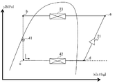
- FIG. 2 is a ph diagram during cooling operation of the air conditioner of FIG. 1.
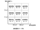
- FIG. 4 is a schematic diagram showing classification of operation modes based on room temperature and relative humidity in the continuous operation mode in the dehumidifying operation of the air-conditioning apparatus of FIG. 3.
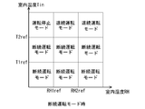
- FIG. 4 is a schematic diagram showing classification of operation modes based on room temperature and relative humidity in the intermittent operation mode in the dehumidifying operation of the air-conditioning apparatus of FIG. 3.
- FIG. 4 is a schematic diagram showing classification of operation modes based on room temperature and relative humidity in the intermittent operation mode in the dehumidifying operation of the air-conditioning apparatus of FIG. 3.
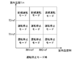
- FIG. 4 is a schematic diagram showing classification of operation modes based on room temperature and relative humidity in the operation stop mode in the dehumidifying operation of the air-conditioning apparatus of FIG. 3. It is a graph which shows the relationship between the temperature in the same absolute humidity, and relative humidity. In the air conditioning apparatus of FIG. 1, it is a graph which shows the time-dependent change of relative humidity at the time of carrying out intermittent operation and continuous operation. It is a flowchart which shows the operation example of the air conditioning apparatus of FIG.
- FIG. 1 is a schematic configuration diagram showing an example of a refrigerant circuit configuration of an air-conditioning apparatus according to an embodiment of the present invention.
- the air conditioner 1 of FIG. 1 is installed in a building, a condominium, etc., for example, and is used for cooling and heating of the air-conditioning object area
- the relationship of the size of each component may be different from the actual one.
- the air conditioner 1 mainly includes an outdoor unit 2 as a heat source unit, and indoor units 4A and 4B as a plurality of utilization units connected in parallel to the outdoor unit 2.
- indoor units 4A and 4B as a plurality of utilization units connected in parallel to the outdoor unit 2.
- FIG. 1 the case where two indoor units 4A and 4B are connected is illustrated, but one indoor unit may be connected, or three or more units may be connected. Also good.
- the air conditioning apparatus 1 has the refrigerant circuit 10 with which the outdoor unit 2 and indoor unit 4A, 4B were connected by refrigerant
- the indoor units 4A and 4B are embedded units embedded in the ceiling of a room such as a building, suspended hanging types, or wall-mounted type indoor units that are hung on the wall surface of the room. In response to the supply of cold heat, cooling air is supplied to each of the conditioned rooms.
- FIG. 1 the case where indoor unit 4A, 4B has the respectively same structure is illustrated.
- Each of the indoor units 4A and 4B includes an expansion device 41 as an expansion mechanism, an evaporator 42 as a use side heat exchanger connected in series to the expansion device 41, an indoor fan 43 that blows air to the evaporator 42, And a vane 44 that adjusts the blowing angle of the fan 43 into the conditioned room.
- the expansion device 41 is installed on the liquid side of the evaporator 42 and expands the refrigerant by decompressing it in order to adjust the flow rate of the refrigerant flowing in the indoor refrigerant circuit.
- the expansion device 41 is constituted by, for example, an electronic expansion valve whose opening degree can be variably controlled.
- the evaporator 42 is an indoor heat exchanger that is installed indoors, for example, and performs heat exchange between a heat medium (for example, air or water) and a refrigerant to cool indoor air.
- the type of the evaporator 42 is not particularly limited.
- the evaporator 42 may be constituted by a cross fin type fin-and-tube heat exchanger composed of heat transfer tubes and a large number of fins.
- the indoor fan 43 is supplied to the room as supply air after heat exchange with the refrigerant in the evaporator 42.
- the indoor fan 43 can change the air volume of the air supplied to the evaporator 42, and is composed of, for example, a centrifugal fan or a multiblade fan driven by a DC fan motor.
- the evaporator 42 may perform heat exchange with a heat medium (for example, water or brine) different from the refrigerant and air.
- the vane 44 adjusts the blowing angle of the air blown from the indoor fan 43 through the evaporator 42 into the conditioned room.
- the outdoor unit 2 has a function of supplying cold or warm heat to the indoor units 4A and 4B, and is installed outside a building or the like, for example.
- the outdoor unit 2 is connected to the indoor units 4 ⁇ / b> A and 4 ⁇ / b> B by a refrigerant pipe and constitutes a part of the refrigerant circuit 10. That is, the outdoor unit 2 and the indoor units 4A and 4B are configured to allow refrigerant to flow through the refrigerant pipe.
- a compressor 21 and a condenser 23 as a heat source side heat exchanger are connected in series.
- the compressor 21 sucks refrigerant and compresses the refrigerant to bring it into a high temperature / high pressure state.
- the compressor 21 can vary its operating capacity, and may be composed of a positive displacement compressor driven by a motor whose frequency is controlled by an inverter, for example.
- the present invention is not limited thereto, and two or more compressors 21 are extended in parallel according to the number of indoor units 4A and 4B. May be installed.
- the condenser 23 is, for example, an outdoor heat exchanger installed outdoors, and performs heat exchange between a heat medium (for example, air or water) and a refrigerant to condense and liquefy the refrigerant.
- the condenser 23 is not particularly limited in its form, and is composed of, for example, a cross fin type fin-and-tube heat exchanger composed of heat transfer tubes and a large number of fins.
- the outdoor unit 2 has an outdoor fan 24 as a blower for sucking outdoor air into the unit and exchanging heat with the refrigerant in the condenser 23 and then discharging it to the outside.
- the outdoor fan 24 can change the air volume of the air supplied to the condenser 23, and includes, for example, a propeller fan driven by a motor including a DC fan motor.
- the condenser 23 is not limited to the above configuration, and may perform heat exchange with a heat medium (for example, water or brine) different from the refrigerant and air.
- FIG. 2 is a graph showing a ph diagram during the cooling operation of the air conditioner of FIG. 1, and an operation example of the air conditioner will be described with reference to FIGS.
- the low-temperature and low-pressure refrigerant is compressed by the compressor 21 and discharged as a high-temperature and high-pressure gas refrigerant (point a shown in FIG. 2).
- the high-temperature and high-pressure gas refrigerant discharged from the compressor 21 flows into the condenser 23.
- the refrigerant flowing into the condenser 23 is condensed and liquefied while dissipating heat to the outdoor air by the blowing action of the outdoor fan 24 (point b shown in FIG. 2).
- the high-pressure liquid refrigerant flowing out of the condenser 23 is decompressed by the expansion device 41 to become a low-pressure gas-liquid two-phase refrigerant (point c shown in FIG. 2), and flows out of the outdoor unit 2.
- the low-pressure gas refrigerant that has flowed out of the outdoor unit 2 flows into the indoor units 4A and 4B, flows into the evaporator 42, and is converted into evaporative gas by absorbing heat from the air by the blowing action of the indoor fan 43 (point d shown in FIG. 2). ).
- the conditioned room is cooled by the evaporator 42 and the indoor fan 43.
- the refrigerant flows into the outdoor unit 2 and is sucked into the compressor 21 again.
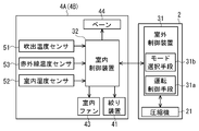
- FIG. 3 is a block diagram showing a configuration of the air conditioner of FIG.
- the outdoor unit 2 is provided with an outdoor control device 31 that controls the operation of each device in the outdoor unit 2.
- the indoor units 4A and 4B each have an indoor unit 4A.
- An indoor control device 32 that controls the operation of each device in 4B is provided.
- the outdoor control device 31 and the indoor control device 32 are connected so as to be able to transmit information, and the outdoor control device 31 and the indoor control device 32 cooperate to perform operation control of the entire air conditioner 1. Yes.
- the outdoor control device 31 and the indoor control device 32 perform control based on outputs from various sensors. Specifically, on the indoor air intake side of the indoor units 4A and 4B, the blowout temperature sensor 51 that detects the temperature of the air sucked into the evaporator 42 as the suction temperature T1, and the evaporator 42 sucks the air.
- An indoor humidity sensor 52 that detects the humidity of the air as the indoor humidity RH, and an infrared temperature that is installed on the ceiling surface of the conditioned room and measures the surface temperature of the indoor wall surface, floor surface, or person in the room as the infrared temperature T2 from above. And a sensor 53.
- a set temperature of the conditioned room is set in the indoor control device 32, and the indoor control device 32 controls the suction temperature T1 or the infrared temperature T2 (room temperature Tin) to be the set temperature. Further, a refrigerant inlet temperature sensor 54 and a refrigerant outlet temperature sensor 55 are provided at the inlet and outlet of the evaporator 42, respectively, so that the degree of superheat at the outlet of the evaporator 42 can be calculated.
- the air conditioner 1 has a function of performing a dehumidifying operation for dehumidifying the conditioned room in addition to the above-described cooling operation (see FIG. 2). At this time, the air conditioner 1 performs a weak cooling and dehumidifying operation in which the refrigerant flow is the same as that in the cooling operation, but the sensible heat ratio (SHF) is lower than that in the cooling operation. Further, during the dehumidifying operation, the outdoor control device 31 and the indoor control device 32 control the operation according to the state of the conditioned room.
- SHF sensible heat ratio
- the outdoor control device 31 and the indoor control device 32 are classified into three states of a conditioned room, a high temperature state, a low temperature and high humidity state, and a low temperature and low humidity state based on the indoor temperature Tin and the indoor humidity RH.
- the control of the compressor 21, the expansion device 41, the indoor fan 43, and the like is changed according to the state, and control is performed so as to perform an operation with a small compressor input while maintaining a comfortable state.
- the outdoor control device 31 has operation control means 31a and mode selection means 31b.
- the operation control means 31a controls the operations of the outdoor unit 2 and the refrigerant circuit 10 and controls the operations of the indoor units 4A and 4B via the indoor control device 32.
- the operation control means 31a determines the increase rate of the compressor frequency based on the temperature difference between the indoor temperature Tin and the set temperature, and determines the frequency of the compressor 21. Further, when performing the dehumidifying operation, the operation control means 31a lowers the evaporation temperature in the refrigerant circuit than during the cooling operation and performs the weak cooling and dehumidifying operation so that the sensible heat ratio is lower than that during the cooling operation. To control.
- the mode selection means 31b performs the dehumidifying operation in any one of the continuous operation mode, the intermittent operation mode or the operation stop mode based on the indoor temperature Tin and the indoor humidity RH when performing the dehumidifying operation described above. To choose. Then, the operation control unit 31a performs control according to the operation mode selected by the mode selection unit 31b.
- the continuous operation mode is a dehumidifying operation mode in a state where the indoor temperature Tin is high, and is a mode in which the refrigerant circuit 10 continuously operates.
- the intermittent operation mode is a dehumidification operation mode in a state where the room temperature is low and the humidity is high, and the refrigerant circuit 10 periodically repeats operation and stop.
- the operation stop mode is a mode in which the operation of the refrigerant circuit 10 is stopped when the humidity is low and dehumidification is not necessary.
- the mode selection means 31b compares the suction temperature T1 and the infrared temperature T2 and applies the higher one as the room temperature Tin.
- the dehumidifying operation following the load can be realized by installing the infrared temperature sensor 53 on the ceiling surface and grasping the temperature state of the lower part of the room. That is, in the past, there was a temperature sensor only at the suction port on the ceiling surface of the room, so in a conference room or the like, when the number of people increased rapidly, the sensor measurement value could not follow the increased load, and the uncomfortable state continued There is. Therefore, the mode selection means 31b can compare the suction temperature T1 and the infrared temperature T2, apply the higher one as the room temperature Tin, and realize a dehumidifying operation that immediately follows the load. Yes.
- the mode selection means 31b has a first temperature threshold value T1ref, a second temperature threshold value T2ref, and a humidity threshold value (lower limit humidity threshold value RH1ref and upper limit humidity threshold value RH2ref).
- the operation mode is selected according to the region to which the room temperature Tin and the room humidity RH of the harmony room belong.
- the mode selection means 31b selects the continuous operation mode at the start of the dehumidifying operation.
- the lower limit humidity threshold RH1ref is set to, for example, 40% relative humidity
- the upper limit humidity threshold RH2ref is set to, for example, 60% relative humidity.
- the relative humidity is set to 40% and 60% as the set humidity thresholds RH1ref and RH2, but the humidity is not limited to this. It is sufficient if the humidity is set so as to create a clean space.
- FIG. 4 is a schematic diagram showing classification of operation modes based on room temperature and relative humidity in the continuous operation mode in the dehumidifying operation of the air conditioning apparatus of FIG.
- the mode selection unit 31b selects the continuous operation mode regardless of the room humidity RH. Then, the mode selection means 31b switches from the continuous operation mode to the intermittent operation mode or the operation stop mode when the room temperature Tin becomes equal to or lower than the first temperature threshold value T1ref during the continuous operation mode. Specifically, the mode selection means 31b selects the intermittent operation mode when the indoor humidity RH is larger than the lower limit humidity threshold RH1ref (relative humidity 40%). On the other hand, the mode selection unit 31b selects an operation stop mode in which the operation of the refrigerant circuit 10 is stopped when the indoor humidity RH is equal to or lower than the lower limit humidity threshold value RH1ref (relative humidity 40%).
- FIG. 5 is a schematic diagram showing classification of operation modes based on room temperature and relative humidity in the intermittent operation mode in the dehumidifying operation of the air conditioning apparatus of FIG.
- the mode selection means 31b continues the intermittent operation mode when the room temperature Tin is equal to or lower than the second temperature threshold value T2ref higher than the first temperature threshold value T1ref. That is, even if the room temperature Tin becomes higher than the first temperature threshold value T1ref, the operation mode is not switched and the intermittent operation mode is continued.
- the mode selection unit 31b selects the continuous operation mode again.
- FIG. 6 is a schematic diagram showing classification of operation modes based on room temperature and relative humidity in the operation stop mode in the dehumidifying operation of the air conditioning apparatus of FIG.
- the mode selection unit 31b determines that the indoor humidity RH is higher than the upper limit humidity threshold RH2ref (relative humidity 60%) when the indoor temperature Tin is higher than the second temperature threshold T2ref.
- the continuous operation mode with high latent heat capability is selected, and when the room humidity RH is lower than the upper limit humidity threshold RH2ref (relative humidity 60%), the intermittent operation mode is selected.
- a comfortable space suitable for the state can be formed with low power consumption, and hunting when the operation is switched can be prevented. That is, when the refrigerant circuit 10 performs the dehumidifying operation in the intermittent operation mode, a comfortable environment can be obtained while suppressing a decrease in the indoor temperature Tin. Further, since the relative humidity is likely to decrease during the intermittent operation mode, it is easy to shift to the operation stop mode that is a low-temperature and low-humidity state, and power consumption can be suppressed.
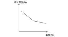
- FIG. 7 is a graph showing the relationship between temperature and relative humidity at the same absolute humidity.
- the relative humidity decreases as the temperature increases under the same absolute humidity.
- the continuous operation mode the room temperature decreases and the relative humidity increases.
- the relative humidity is lowered although the absolute humidity is higher than that in the continuous operation.
- the intermittent operation mode even when the indoor temperature Tin becomes higher than the first temperature threshold value T1ref, the intermittent operation mode is continued, and when the indoor temperature Tin becomes higher than the second temperature threshold value T2ref, It switches to continuous operation mode again. As a result, it is possible to suppress power consumption by promoting a decrease in relative humidity accompanying an increase in the room temperature Tin.
- the mode selection unit 31b selects the operation stop mode.
- FIG. 8 is a graph showing changes in relative humidity and absolute humidity over time when the compressor frequency is fixed and when it is continuously operated and when it is intermittently operated. As shown in FIG. 8, the time until the relative humidity reaches 40% is 35 minutes for intermittent operation and 90 minutes for continuous operation. Further, even in the intermittent operation mode, it is possible to suppress a decrease in the room temperature Tin even in a low humidity state where the air conditioner is stopped.
- the operation control means 31a controls the air volume of the indoor fan 43 to be smaller in the intermittent operation mode than in the continuous operation mode.
- the operation control means 31a controls the indoor fan 43 to output a minimum air volume via the indoor control device 32.
- the driving frequency of the compressor 21 is determined by the temperature difference between the indoor temperature Tin and the set temperature. When the conditioned room is in a low temperature state, the driving frequency of the compressor 21 is lower and the evaporation temperature is higher than in the high temperature state. Become.
- the operation control means 31a performs control so that the aperture amount of the expansion device 41 is smaller in the intermittent operation mode than in the continuous operation mode.
- the operation control means 31a controls the expansion device 41 so that the outlet superheat degree of the evaporator 42 becomes 10 ° C.
- the amount of dehumidification is increased and the power consumption is reduced when the opening degree of the expansion device 41 is reduced as compared with the continuous operation mode in the room to be conditioned. be able to.
- the operation control means 31a has a function of controlling the area of the outlet by changing the angle of the vane 44 in accordance with the air volume of the indoor fan 43 in order to obtain a comfortable space with a low input. Specifically, the operation control means 31a sets the vane angle to the most open state when the fan air volume is maximum, changes the vane angle according to the decrease in the fan air volume, and closes the outlet when the fan stops. To control.
- the air blowing control means changes the angle of the vane 44 according to the air volume of the indoor fan 43 to change the area of the outlet. Thereby, the speed of the blown air is stabilized, and the occurrence of condensation and dew jumping can be prevented.
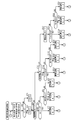
- FIG. 9 is a flowchart showing an operation example of the air conditioner of FIG. 1, and an operation example of the air conditioner 1 will be described with reference to FIGS.
- the suction temperature T1, the indoor humidity RH, and the infrared temperature T2 are measured by the blowing temperature sensor 51, the indoor humidity sensor 52, and the infrared temperature sensor 53 (step ST1). .
- the suction temperature T1 and the infrared temperature T2 are compared (step ST2), and the higher temperature among the suction temperature T1 and the infrared temperature T2 is determined as the indoor temperature Tin (steps ST3 and ST4).
- step ST5 it is determined whether or not the dehumidifying operation mode is the continuous operation mode (step ST5).
- the continuous operation mode is selected at the start of the dehumidifying operation.
- the operation mode is the continuous operation mode
- it is determined whether the room temperature Tin is higher than the first temperature threshold value T1ref (see step ST6, FIG. 4).
- the continuous operation mode is continued (step ST7).
- the dehumidifying operation in the continuous operation mode is performed, the indoor temperature Tin and the indoor humidity RH gradually decrease. Then, the continuous operation mode is continued until the room temperature Tin becomes equal to or lower than the first temperature threshold value T1ref (step ST1 to step ST7).
- step ST8 when the room temperature Tin becomes equal to or lower than the first temperature threshold value T1ref, it is determined whether or not the room humidity RH is larger than the lower limit humidity threshold value RH1ref (step ST8).
- the operation stop mode is selected on the assumption that the dehumidification has been sufficiently performed until it becomes comfortable, and the operation of the refrigerant circuit 10 is stopped (step ST9).
- the indoor humidity RH is larger than the lower limit humidity threshold RH1ref
- the intermittent operation mode is selected and the intermittent operation mode is performed because the low temperature and high humidity state is set (step ST10). Then, the room temperature Tin increases as compared with the continuous operation mode, and the relative humidity decreases accordingly.
- step ST11 it is determined whether or not the room temperature Tin is lower than the second temperature threshold value T2ref (step ST12).
- the intermittent operation mode is continued (step ST13). At this time, the room temperature Tin of the conditioned room increases, the indoor humidity RH decreases, and the comfort of the conditioned room improves while suppressing power consumption.
- step ST12 When the room temperature Tin becomes equal to or higher than the second temperature threshold value T2ref (step ST12), it is determined whether the room humidity RH is higher than the lower limit humidity threshold value RH1ref (step ST14).
- the operation stop mode is selected on the assumption that the dehumidification has been sufficiently performed until it becomes comfortable, and the operation of the refrigerant circuit 10 is stopped (step ST15).
- the intermittent operation mode is switched to the continuous operation mode again (step ST16).
- step ST17 the room temperature Tin and the room humidity RH are constantly monitored, and the operation continues to stop while the room temperature Tin is smaller than the second temperature threshold value T2ref (step ST19).
- step ST18 when the room temperature Tin becomes equal to or higher than the second temperature threshold value T2ref (step ST18), the continuous operation mode or the intermittent operation mode is resumed again.
- the indoor humidity RH is larger than the upper limit humidity threshold RH2ref (step ST20)
- step ST21 the indoor humidity RH is less than or equal to the upper limit humidity threshold RH2ref.
- the intermittent operation mode is selected (step ST22).
- the intermittent operation mode is performed after the indoor temperature Tin is lowered to the first temperature threshold value T1ref in the continuous operation mode, and the indoor temperature Tin rises to the second temperature threshold value T2, or the indoor humidity RH is the lower limit.
- the humidity threshold value falls below RH1ref
- comfort can be improved by utilizing the decrease in relative humidity due to temperature rise, thus creating a comfortable space while suppressing power consumption.
- Dehumidification can be performed.
- the dehumidification amount is increased in the intermittent operation mode when the conditioned room is in a low temperature and high humidity state. Can be suppressed. Furthermore, by controlling so that the throttle amount of the expansion device 41 is smaller in the intermittent operation mode than in the continuous operation mode, the dehumidification amount in the intermittent operation mode can be increased and the power consumption can be suppressed.
- the angle of the vane 44 is changed according to the air volume of the indoor fan 43 to control the area of the air outlet, thereby preventing the air outlet from being dewed or jumping out. can do.
- the embodiment of the present invention is not limited to the above embodiment.
- the air conditioner 1 that performs the cooling operation is illustrated, but the heating operation may be performed as well as the cooling operation.
- a flow path switch composed of a four-way valve or the like is provided on the discharge side of the compressor 21 so that the cooling flow path during the cooling operation and the heating flow path during the heating operation can be switched.
- FIG 3 illustrates the case where the operation control means 31a and the mode selection means 31b are provided on the outdoor control device 31 side, but may be provided on the indoor control device 32 side or an outdoor unit. 2 and the indoor unit 4 may be provided on the control unit side of the air-conditioning apparatus 1 formed separately.
Landscapes
- Engineering & Computer Science (AREA)
- Chemical & Material Sciences (AREA)
- Combustion & Propulsion (AREA)
- Mechanical Engineering (AREA)
- General Engineering & Computer Science (AREA)
- Signal Processing (AREA)
- Physics & Mathematics (AREA)
- Fuzzy Systems (AREA)
- Mathematical Physics (AREA)
- Fluid Mechanics (AREA)
- Air Conditioning Control Device (AREA)
Abstract
Description
図1の空気調和装置1は、たとえばビルやマンション等に設置され、蒸気圧縮式の冷媒回路運転を行なうことによって、設置される空調対象域の冷房や暖房に使用されるものである。なお、図1を含め、以下の図面では各構成部材の大きさの関係が実際のものとは異なる場合がある。
空気調和装置1は、主として、熱源機としての室外機2と、室外機2に並列に接続された複数台の利用ユニットとしての室内機4A、4Bとを有している。なお、図1において、2台の室内機4A、4Bが接続されている場合について例示しているが、1台接続されたものであってもよいし、3台以上接続されたものであってもよい。そして、空気調和装置1は、室外機2と室内機4A、4Bとが冷媒配管により接続された冷媒回路10を有している。
Claims (8)
- 圧縮機、凝縮器、減圧装置及び蒸発器を冷媒配管により接続した冷媒回路と、
前記蒸発器による空気調和が行われる被調和室の湿度を室内湿度として計測する湿度センサと、
前記被調和室の温度を室内温度として計測する温度センサと、
前記蒸発器から冷気が供給される除湿運転を行うように前記冷媒回路を制御する運転制御手段と、
前記湿度センサ及び前記温度センサにおいて計測された室内湿度及び室内温度に基づいて、前記除湿運転時に前記運転制御手段において制御される運転モードとして、前記冷媒回路が連続的に運転する連続運転モードと、前記冷媒回路が断続的に運転する断続運転モードと、前記冷媒回路が停止する運転停止モードとを選択するモード選択手段と
を備え、
前記モード選択手段は、
前記連続運転モード時において室内温度が設定された第1温度しきい値以下であって室内湿度が設定された湿度しきい値より大きい場合には前記断続運転モードを選択し、
前記断続運転モード時において室内温度が、前記第1温度しきい値よりも高く設定された第2温度しきい値以下であって、室内湿度が設定された湿度しきい値以下の場合、前記運転停止モードを選択するものである
ことを特徴とする空気調和装置。 - 前記モード選択手段は、前記連続運転モード時において、
室内温度が前記第1温度しきい値以下であって室内湿度が湿度しきい値以下である場合、前記連続運転モードから前記運転停止モードに切り替えることを特徴とする請求項1に記載の空気調和装置。 - 前記モード選択手段は、前記断続運転モード時において、
室内温度が前記第2温度しきい値以下であって室内湿度が設定された湿度しきい値より大きい場合、前記断続運転モードから前記連続運転モードに切り替えることを特徴とする請求項1又は2に記載の空気調和装置。 - 前記モード選択手段は、前記運転停止モード時において、
室内温度が前記第2温度しきい値以下の場合は前記運転停止モードを継続し、
室内温度が前記第2温度しきい値より大きく室内湿度が設定された湿度しきい値より大きい場合、前記断続運転モードから前記連続運転モードに切り替え、
室内温度が前記第2温度しきい値より大きく室内湿度が設定された湿度しきい値より小さい場合、前記断続運転モードから前記連続運転モードに切り替えるものである
ことを特徴とする請求項1~3のいずれか1項に記載の空気調和装置。 - 前記蒸発器に送風を行う室内ファンをさらに有し、
前記運転制御手段は、断続運転時の送風量が連続運転時の総風量に比べて小さくなるように前記室内ファンを制御することを特徴とする請求項1~4のいずれか1項に記載の空気調和装置。 - 前記室内ファンによる送風の吹出し角度を調整するベーンをさらに備え、
前記運転制御手段は、前記室内ファンの風量に応じて吹出し開口部面積を小さくなるように前記ベーンの角度を調整する機能を有することを特徴とする請求項5に記載の空気調和装置。 - 前記運転制御手段は、前記断続運転モード時の開度が前記連続運転モード時の開度よりも小さくなるように前記減圧装置を制御するものであることを特徴とする請求項1~6のいずれか1項に記載の空気調和装置。
- 前記蒸発器の吸込口に設置され、前記蒸発器に吸い込まれる空気の温度を吸込温度として計測する吸込温度センサと、
前記被調和室内に設けられ、前記被調和室の温度を赤外線温度として計測する赤外線温度センサと
をさらに有し、
前記モード選択手段は、前記赤外線温度が前記吸込温度よりも高い場合、前記赤外線温度を室内温度として用い、前記吸込温度が前記赤外線温度よりも高い場合、前記吸込温度を室内温度として用いることを特徴とする請求項1~7のいずれか1項に記載の空気調和装置。
Priority Applications (5)
| Application Number | Priority Date | Filing Date | Title |
|---|---|---|---|
| CN201380081304.9A CN105814369B (zh) | 2013-12-19 | 2013-12-19 | 空调装置 |
| EP13899861.2A EP3086048B1 (en) | 2013-12-19 | 2013-12-19 | Air-conditioning device |
| PCT/JP2013/084003 WO2015092895A1 (ja) | 2013-12-19 | 2013-12-19 | 空気調和装置 |
| JP2015553283A JP6017068B2 (ja) | 2013-12-19 | 2013-12-19 | 空気調和装置 |
| US15/035,365 US10151505B2 (en) | 2013-12-19 | 2013-12-19 | Air-conditioning apparatus |
Applications Claiming Priority (1)
| Application Number | Priority Date | Filing Date | Title |
|---|---|---|---|
| PCT/JP2013/084003 WO2015092895A1 (ja) | 2013-12-19 | 2013-12-19 | 空気調和装置 |
Publications (1)
| Publication Number | Publication Date |
|---|---|
| WO2015092895A1 true WO2015092895A1 (ja) | 2015-06-25 |
Family
ID=53402290
Family Applications (1)
| Application Number | Title | Priority Date | Filing Date |
|---|---|---|---|
| PCT/JP2013/084003 Ceased WO2015092895A1 (ja) | 2013-12-19 | 2013-12-19 | 空気調和装置 |
Country Status (5)
| Country | Link |
|---|---|
| US (1) | US10151505B2 (ja) |
| EP (1) | EP3086048B1 (ja) |
| JP (1) | JP6017068B2 (ja) |
| CN (1) | CN105814369B (ja) |
| WO (1) | WO2015092895A1 (ja) |
Cited By (7)
| Publication number | Priority date | Publication date | Assignee | Title |
|---|---|---|---|---|
| EP3299732A1 (en) * | 2016-09-23 | 2018-03-28 | Daikin Industries, Limited | System for air-conditioning and hot-water supply |
| JP2018071794A (ja) * | 2016-10-24 | 2018-05-10 | 株式会社竹中工務店 | 空調システム |
| WO2019146377A1 (ja) * | 2018-01-23 | 2019-08-01 | ダイキン工業株式会社 | 空気調和装置 |
| WO2019146355A1 (ja) * | 2018-01-23 | 2019-08-01 | ダイキン工業株式会社 | 空気調和装置 |
| JP2020034183A (ja) * | 2018-08-27 | 2020-03-05 | シャープ株式会社 | 空気調和機 |
| JP2020532700A (ja) * | 2017-09-04 | 2020-11-12 | 海尓集団公司 | 空気調和機を制御する方法、及び装置 |
| JP7822530B1 (ja) * | 2025-02-17 | 2026-03-02 | 三菱電機株式会社 | 空気調和機、及び制御方法 |
Families Citing this family (11)
| Publication number | Priority date | Publication date | Assignee | Title |
|---|---|---|---|---|
| US10837670B2 (en) * | 2016-08-09 | 2020-11-17 | Mitsubishi Electric Corporation | Air-conditioning apparatus |
| CN107101286B (zh) * | 2017-06-01 | 2022-09-30 | 广东申菱环境系统股份有限公司 | 一种蒸发冷却除湿空调机组及其控制方法 |
| CN109386937A (zh) * | 2017-08-07 | 2019-02-26 | 大连新明华电子科技有限公司 | 恒温恒湿高性能红酒柜控制方法 |
| CN107676924B (zh) * | 2017-08-17 | 2020-09-01 | 深圳市艾特智能科技有限公司 | 除湿机的控制方法、系统、可读存储介质及智能设备 |
| EP3677852B1 (en) * | 2017-09-04 | 2025-10-08 | Haier Group Corporation | Control method and apparatus for self-cleaning of air conditioner, and air conditioner |
| JP6687663B2 (ja) * | 2018-04-12 | 2020-04-28 | ファナック株式会社 | 筐体の内部の熱を外部に放出する熱移動装置を備えるレーザ装置 |
| CN110094856A (zh) * | 2019-04-15 | 2019-08-06 | 青岛海尔空调电子有限公司 | 空调器及其送风控制方法 |
| CN113465156A (zh) * | 2020-03-30 | 2021-10-01 | 广东美的制冷设备有限公司 | 制冷装置的控制方法及制冷装置 |
| CN113915745B (zh) * | 2020-07-09 | 2023-08-04 | 海信空调有限公司 | 一种空调器和预睡眠模式的控制方法 |
| US11781766B2 (en) * | 2020-11-25 | 2023-10-10 | Research Products Corporation | System and method for humidification temperature compensation |
| KR20250123583A (ko) * | 2024-02-08 | 2025-08-18 | 엘지전자 주식회사 | 냉장고 및 이의 제어 방법 |
Citations (7)
| Publication number | Priority date | Publication date | Assignee | Title |
|---|---|---|---|---|
| JPS61173045A (ja) * | 1985-01-24 | 1986-08-04 | Toshiba Corp | 空気調和機 |
| JPH0424611B2 (ja) | 1983-04-08 | 1992-04-27 | Hitachi Ltd | |
| JP2001021196A (ja) * | 1999-07-05 | 2001-01-26 | Matsushita Electric Ind Co Ltd | 空気調和機の除湿制御方法 |
| JP2002005492A (ja) * | 2000-06-20 | 2002-01-09 | Fujitsu General Ltd | 加湿器 |
| JP2008175490A (ja) * | 2007-01-19 | 2008-07-31 | Mitsubishi Heavy Ind Ltd | 空気調和装置 |
| JP2009068729A (ja) * | 2007-09-11 | 2009-04-02 | Toyotomi Co Ltd | 熱交換器温度検出に依存する空気調和機の制御方法 |
| JP2012122629A (ja) * | 2010-12-06 | 2012-06-28 | Mitsubishi Electric Corp | 空気調和機 |
Family Cites Families (13)
| Publication number | Priority date | Publication date | Assignee | Title |
|---|---|---|---|---|
| JPH0424611A (ja) | 1990-05-18 | 1992-01-28 | Seiko Instr Inc | コントラスト自動調整機能付液晶表示装置 |
| US5743103A (en) * | 1995-10-23 | 1998-04-28 | Mitsubishi Jokogyo Kabushiki Kaisha | Air conditioner |
| US6070110A (en) * | 1997-06-23 | 2000-05-30 | Carrier Corporation | Humidity control thermostat and method for an air conditioning system |
| JP3964059B2 (ja) * | 1998-09-25 | 2007-08-22 | 清記 須山 | 室内自動換気システム |
| CN1242219C (zh) * | 2001-12-18 | 2006-02-15 | 乐金电子(天津)电器有限公司 | 空调器的定温除湿运行方式 |
| GB0307910D0 (en) * | 2003-04-05 | 2003-05-14 | Ebac Ltd | Dehumidifier control system |
| JP4719538B2 (ja) * | 2004-10-12 | 2011-07-06 | 株式会社日立製作所 | 空気調和システム |
| US9347676B2 (en) * | 2006-10-26 | 2016-05-24 | Lennox Industries Inc. | Enhanced dehumidification control with variable condenser reheat |
| US8459053B2 (en) * | 2007-10-08 | 2013-06-11 | Emerson Climate Technologies, Inc. | Variable speed compressor protection system and method |
| US20110198404A1 (en) * | 2010-02-18 | 2011-08-18 | Hans Dropmann | Automatic air duct register |
| CN102252367B (zh) * | 2010-05-17 | 2014-04-30 | 海尔集团公司 | 出风口在下部的空调器以及空调器的除霜和除湿方法 |
| JP5085716B2 (ja) * | 2010-11-02 | 2012-11-28 | 株式会社東芝 | サーバ室管理用の空調システム、およびこれを利用したサーバ管理用システム、空調制御方法 |
| CN102767873B (zh) * | 2012-08-02 | 2015-01-21 | 广东芬尼克兹节能设备有限公司 | 健康舒适节能空调器及对空气的处理方法 |
-
2013
- 2013-12-19 EP EP13899861.2A patent/EP3086048B1/en not_active Not-in-force
- 2013-12-19 US US15/035,365 patent/US10151505B2/en active Active
- 2013-12-19 CN CN201380081304.9A patent/CN105814369B/zh not_active Expired - Fee Related
- 2013-12-19 JP JP2015553283A patent/JP6017068B2/ja not_active Expired - Fee Related
- 2013-12-19 WO PCT/JP2013/084003 patent/WO2015092895A1/ja not_active Ceased
Patent Citations (7)
| Publication number | Priority date | Publication date | Assignee | Title |
|---|---|---|---|---|
| JPH0424611B2 (ja) | 1983-04-08 | 1992-04-27 | Hitachi Ltd | |
| JPS61173045A (ja) * | 1985-01-24 | 1986-08-04 | Toshiba Corp | 空気調和機 |
| JP2001021196A (ja) * | 1999-07-05 | 2001-01-26 | Matsushita Electric Ind Co Ltd | 空気調和機の除湿制御方法 |
| JP2002005492A (ja) * | 2000-06-20 | 2002-01-09 | Fujitsu General Ltd | 加湿器 |
| JP2008175490A (ja) * | 2007-01-19 | 2008-07-31 | Mitsubishi Heavy Ind Ltd | 空気調和装置 |
| JP2009068729A (ja) * | 2007-09-11 | 2009-04-02 | Toyotomi Co Ltd | 熱交換器温度検出に依存する空気調和機の制御方法 |
| JP2012122629A (ja) * | 2010-12-06 | 2012-06-28 | Mitsubishi Electric Corp | 空気調和機 |
Non-Patent Citations (1)
| Title |
|---|
| See also references of EP3086048A4 |
Cited By (13)
| Publication number | Priority date | Publication date | Assignee | Title |
|---|---|---|---|---|
| JP2019529857A (ja) * | 2016-09-23 | 2019-10-17 | ダイキン工業株式会社 | 空調給湯システム |
| WO2018056179A1 (en) * | 2016-09-23 | 2018-03-29 | Daikin Industries, Ltd. | System for air-conditioning and hot-water supply |
| EP3299732A1 (en) * | 2016-09-23 | 2018-03-28 | Daikin Industries, Limited | System for air-conditioning and hot-water supply |
| US11867414B2 (en) | 2016-09-23 | 2024-01-09 | Daikin Industries, Ltd. | System for air-conditioning and hot-water supply |
| JP2018071794A (ja) * | 2016-10-24 | 2018-05-10 | 株式会社竹中工務店 | 空調システム |
| JP7033652B2 (ja) | 2017-09-04 | 2022-03-10 | 海尓集団公司 | 空気調和機を制御する方法、及び装置 |
| JP2020532700A (ja) * | 2017-09-04 | 2020-11-12 | 海尓集団公司 | 空気調和機を制御する方法、及び装置 |
| WO2019146377A1 (ja) * | 2018-01-23 | 2019-08-01 | ダイキン工業株式会社 | 空気調和装置 |
| JP2019128075A (ja) * | 2018-01-23 | 2019-08-01 | ダイキン工業株式会社 | 空気調和装置 |
| JP2019128076A (ja) * | 2018-01-23 | 2019-08-01 | ダイキン工業株式会社 | 空気調和装置 |
| WO2019146355A1 (ja) * | 2018-01-23 | 2019-08-01 | ダイキン工業株式会社 | 空気調和装置 |
| JP2020034183A (ja) * | 2018-08-27 | 2020-03-05 | シャープ株式会社 | 空気調和機 |
| JP7822530B1 (ja) * | 2025-02-17 | 2026-03-02 | 三菱電機株式会社 | 空気調和機、及び制御方法 |
Also Published As
| Publication number | Publication date |
|---|---|
| US20160290669A1 (en) | 2016-10-06 |
| EP3086048A1 (en) | 2016-10-26 |
| EP3086048A4 (en) | 2017-08-09 |
| JPWO2015092895A1 (ja) | 2017-03-16 |
| CN105814369A (zh) | 2016-07-27 |
| CN105814369B (zh) | 2019-02-05 |
| JP6017068B2 (ja) | 2016-10-26 |
| EP3086048B1 (en) | 2019-08-28 |
| US10151505B2 (en) | 2018-12-11 |
Similar Documents
| Publication | Publication Date | Title |
|---|---|---|
| JP6017068B2 (ja) | 空気調和装置 | |
| JP5858061B2 (ja) | 換気装置 | |
| JP6906311B2 (ja) | 空気調和装置 | |
| KR20040069613A (ko) | 냉난방기의 절전 제습 운전방법 | |
| CN101149168A (zh) | 定温除湿空调器及其控制方法 | |
| JP5984964B2 (ja) | 空気調和システム | |
| KR20100110423A (ko) | 공기 조화기 및 공기 조화기의 제어 방법 | |
| JP5447360B2 (ja) | 空気調和装置の制御方法 | |
| JP2012141113A (ja) | 空気調和温水機器システム | |
| JP6897848B2 (ja) | 空調システム | |
| CN208765103U (zh) | 热泵系统 | |
| JP3994607B2 (ja) | 空気調和方法 | |
| CN105940275A (zh) | 空调装置 | |
| US11698203B2 (en) | Air-conditioning system | |
| JP6938950B2 (ja) | 空気調和システム | |
| JP2010091209A (ja) | 空調装置 | |
| JP5439792B2 (ja) | 空調装置 | |
| CN113639443A (zh) | 空调器及其控制方法 | |
| JP2017015318A (ja) | 空調調和機 | |
| JP2006275509A (ja) | 空気調和装置の制御方法 | |
| JP2006275507A (ja) | 空気調和装置 | |
| JP7316759B2 (ja) | 空気調和装置及び空気調和システム | |
| JP2001304652A (ja) | 空調機とその制御方法 | |
| JP5435161B2 (ja) | 空調装置 | |
| JP6745895B2 (ja) | 空調システム |
Legal Events
| Date | Code | Title | Description |
|---|---|---|---|
| 121 | Ep: the epo has been informed by wipo that ep was designated in this application |
Ref document number: 13899861 Country of ref document: EP Kind code of ref document: A1 |
|
| ENP | Entry into the national phase |
Ref document number: 2015553283 Country of ref document: JP Kind code of ref document: A |
|
| WWE | Wipo information: entry into national phase |
Ref document number: 15035365 Country of ref document: US |
|
| REEP | Request for entry into the european phase |
Ref document number: 2013899861 Country of ref document: EP |
|
| WWE | Wipo information: entry into national phase |
Ref document number: 2013899861 Country of ref document: EP |
|
| NENP | Non-entry into the national phase |
Ref country code: DE |