WO2015092919A1 - 空気調和機 - Google Patents
空気調和機 Download PDFInfo
- Publication number
- WO2015092919A1 WO2015092919A1 PCT/JP2013/084273 JP2013084273W WO2015092919A1 WO 2015092919 A1 WO2015092919 A1 WO 2015092919A1 JP 2013084273 W JP2013084273 W JP 2013084273W WO 2015092919 A1 WO2015092919 A1 WO 2015092919A1
- Authority
- WO
- WIPO (PCT)
- Prior art keywords
- air conditioner
- fixing
- upper structure
- fixed
- hanging
- Prior art date
- Legal status (The legal status is an assumption and is not a legal conclusion. Google has not performed a legal analysis and makes no representation as to the accuracy of the status listed.)
- Ceased
Links
Images


Classifications
-
- F—MECHANICAL ENGINEERING; LIGHTING; HEATING; WEAPONS; BLASTING
- F24—HEATING; RANGES; VENTILATING
- F24F—AIR-CONDITIONING; AIR-HUMIDIFICATION; VENTILATION; USE OF AIR CURRENTS FOR SCREENING
- F24F13/00—Details common to, or for air-conditioning, air-humidification, ventilation or use of air currents for screening
- F24F13/32—Supports for air-conditioning, air-humidification or ventilation units
-
- F—MECHANICAL ENGINEERING; LIGHTING; HEATING; WEAPONS; BLASTING
- F24—HEATING; RANGES; VENTILATING
- F24F—AIR-CONDITIONING; AIR-HUMIDIFICATION; VENTILATION; USE OF AIR CURRENTS FOR SCREENING
- F24F1/00—Room units for air-conditioning, e.g. separate or self-contained units or units receiving primary air from a central station
- F24F1/0007—Indoor units, e.g. fan coil units
- F24F1/0043—Indoor units, e.g. fan coil units characterised by mounting arrangements
- F24F1/0047—Indoor units, e.g. fan coil units characterised by mounting arrangements mounted in the ceiling or at the ceiling
Definitions
- Embodiment of this invention is related with the air conditioner provided with the indoor unit of the ceiling hanging type, for example.
- the indoor unit In an air conditioner in which an indoor unit containing a blower and an indoor heat exchanger is arranged on the back of the ceiling, the indoor unit is suspended from a beam on the back of the ceiling via a plurality of suspension bolts, for example.
- a plurality of suspension fittings are fixed to the side surface of the unit main body constituting the outline of the indoor unit with screws.
- the suspension fitting projects horizontally from the side surface of the unit body in all directions, and the lower end of the suspension bolt is connected to the tip of the suspension fitting.
- the air conditioner of this embodiment is suspended in the ceiling space of a building via a plurality of suspensions, and includes a unit main body that contains an indoor heat exchanger and a blower that sends air to the heat exchanger, and the unit main body A plurality of hanging brackets provided on an upper structure constituting the upper portion and connected to the lower ends of the hanging tools.
- the upper structure includes an upper plate portion extending in the horizontal direction.
- the hanging bracket includes a connecting portion to which the hanging tool is connected, a first fixing portion fixed to the upper structure via a fastener in a state of being superimposed on the upper structure, and the first fixing. And a second fixing part configured to extend integrally from above and to overlap the upper plate part from above.
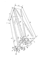
- FIG. 1 is a side view showing a state in which an indoor unit of an air conditioner is installed on the back of a ceiling in the first embodiment.
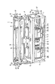
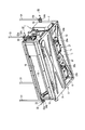
- FIG. 2 is a perspective view of the indoor unit of the air conditioner viewed from behind.
- FIG. 3 is a perspective view of the indoor unit of the air conditioner as viewed from below.
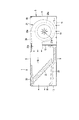
- FIG. 4 is a cross-sectional view of the indoor unit of the air conditioner.
- FIG. 5 is a perspective view of the state in which the indoor unit is suspended by four suspension bolts as viewed from above.
- FIG. 6 is a perspective view of the state in which the indoor unit is suspended by four suspension bolts as viewed from below.
- FIG. 7 is a perspective view showing a state in which a hanging metal fitting is fixed to four corners of the top plate.
- FIG. 8 is a perspective view of a hanging metal fitting.
- FIG. 9 is a perspective view showing the shape of a recess provided in the top plate.
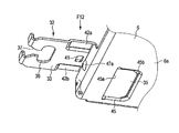
- FIG. 10 is an enlarged perspective view showing a portion F10 in FIG.
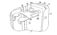
- FIG. 11 is a perspective view showing a state in which the hanging bracket is fixed to the top plate.
- FIG. 12 is a perspective view seen from the direction of arrow F12 in FIG.
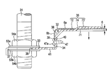
- FIG. 13 is a cross-sectional view showing the positional relationship between the top plate and the hanging bracket.
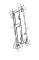
- FIG. 14 is a perspective view showing the positional relationship between the hanging bracket fixed to the top plate and the first side plate.
- FIG. 15 is an enlarged perspective view showing a portion F15 in FIG.
- FIG. 16 is a side view showing a state in which the indoor unit of the air conditioner is installed on the back of the ceiling in the second embodiment.
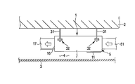
- FIG. 17 is a cross-sectional view showing the positional relationship between the top plate and the hanging bracket in the third embodiment.
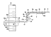
- FIG. 1 is a side view schematically showing a state where an indoor unit of an air conditioner is installed in a space behind a ceiling
- FIG. 2 is a perspective view of the indoor unit.
- the indoor unit 1 is installed, for example, behind the ceiling of a building.
- the back of the ceiling refers to the ceiling space 4 defined between the beam 2 and the ceiling board 3 of the building.
- the indoor unit 1 is a square flat box having a width dimension W, a depth dimension D, and a thickness dimension H.
- the width dimension W of the indoor unit 1 is formed larger than the depth dimension D, and the thickness dimension H is formed sufficiently smaller than the width dimension W and the depth dimension D.
- the indoor unit 1 includes a metal unit body 5.
- the unit main body 5 is an element constituting the outline of the indoor unit 1, and includes a top plate 6, a first side plate 7, a second side plate 8, a bottom plate 9, a front frame 10, a back plate 11, and a partition plate 12. ing.
- the top plate 6 is an example of an upper structure constituting the upper part of the unit body 5. As shown in FIG. 7, the top plate 6 has an upper plate portion 6a extending in the horizontal direction, and a side plate portion 6b continuous to the periphery of the upper plate portion 6a. The side plate portion 6b is bent at a substantially right angle downward from the periphery of the upper plate portion 6a. The side plate portion 6b can be rephrased as a flange portion.
- the first side plate 7 is located at one end along the width direction of the top plate 6.
- the upper end of the first side plate 7 is fixed to the outer surface of the side plate 6 b of the top plate 6 with a plurality of screws, and extends downward from one end of the top plate 6.
- the second side plate 8 is located at the other end along the width direction of the top plate 6.
- the upper side of the second side plate 8 is fixed to the outer surface of the side plate 6 b of the top plate 6 with a plurality of screws, and extends downward from the other end of the top plate 6. For this reason, the first side plate 7 and the second side plate 8 face each other with a gap in the width direction of the top plate 6.
- the bottom plate 9 is fixed to the front frame 10 and the partition plate 12 so as to straddle between the lower end portion of the first side plate 7 and the lower end portion of the second side plate 8 and constitutes the bottom of the unit body 5. .
- the bottom plate 9 has a size that is approximately half the length of the unit body 5 along the depth direction. Therefore, a region of the bottom of the unit body 5 that is out of the bottom plate 9 constitutes an elongated suction port 14.
- the suction port 14 faces a suction grill 15 provided on the ceiling plate 3.
- the front frame 10 is fixed to the front edge of the top plate 6, the front edge of the first side plate 7, and the front edge of the second side plate 8 with a plurality of screws.
- the front frame 10 constitutes an elongated outlet 16 at the front end of the unit body 5.
- an air outlet duct 17 is connected to the air outlet 16.
- the blowout duct 17 is disposed in the ceiling space 4 and is connected to a blowout grill (not shown) provided on the ceiling plate 3.
- the back plate 11 is detachably fixed to the rear edge of the top plate 6, the rear edge of the first side plate 7, and the rear edge of the second side plate 8 with a plurality of screws.
- the back plate 11 has a size corresponding to the suction port 14. Therefore, after the back plate 11 is removed from the rear edge of the top plate 6, the rear edge of the first side plate 7, and the rear edge of the second side plate 8, a plurality of back plates 11 are formed on the bottom of the unit body 5 so as to cover the suction port 14. It can be fixed with screws.
- a region surrounded by the rear edge of the top plate 6, the rear edge of the first side plate 7, and the rear edge of the second side plate 8 functions as a suction port. .
- the partition plate 12 is erected along one side edge of the suction port 14.
- the peripheral edge of the partition plate 12 is abutted against the lower surface of the top plate 6, the inner surface of the first side plate 7, and the inner surface of the second side plate 8. For this reason, the partition plate 12 divides the inside of the unit main body 5 into two chambers, a blower chamber 18 and a heat exchange chamber 19.
- the blower chamber 18 has the suction port 14, and a blower 21 is accommodated in the blower chamber 18.
- the heat exchange chamber 19 has the outlet 16, and an indoor heat exchanger 22 and a drain pan 23 are disposed in the heat exchange chamber 19.
- the blower 21 includes a fan motor 25 and a pair of fans 26a and 26b.
- the fan motor 25 has two rotating shafts 27a and 27b that are coaxially projected from both side surfaces thereof, and the fans 26a and 26b are attached to the rotating shafts 27a and 27b.
- the fans 26a and 26b are surrounded by fan cases 28a and 28b, respectively.
- the fan cases 28a and 28b integrally have nozzle portions 29a and 29b.
- the nozzle portions 29 a and 29 b pass through the partition plate 12 and are opened in the heat exchange chamber 19.
- the indoor heat exchanger 22 is housed in the heat exchange chamber 19 in a strongly forward tilted posture because the thickness dimension of the indoor unit 1 is limited.
- the indoor heat exchanger 22 extends in the width direction of the unit main body 5, and both end portions thereof are supported by the unit main body 5 via side heat insulating materials (not shown). Further, the upper end portion of the indoor heat exchanger 22 is supported by the upper heat insulating material 30.
- the upper heat insulating material 30 is interposed between the upper end portion of the indoor heat exchanger 22 and the top plate 6. The side heat insulating material and the upper heat insulating material 30 suppress the heat generated by the refrigeration cycle action of the indoor heat exchanger 22 from being transmitted to the unit body 5.
- the drain pan 23 is disposed below the indoor heat exchanger 22.
- the drain pan 23 is made of a heat insulating material such as polystyrene foam.
- the drain pan 23 supports the indoor heat exchanger 22 from below and receives drain water dripped from the indoor heat exchanger 22.
- the fans 26a and 26b When the fans 26a and 26b are rotated by the fan motor 25, the fans 26a and 26b suck in air from the axial direction, and discharge the sucked air from the outer peripheral surfaces of the fans 26a and 26b to the inside of the fan cases 28a and 28b. Therefore, as indicated by arrows in FIGS. 1 and 4, the air in the building interior is sucked into the blower chamber 18 from the suction grill 15 of the ceiling plate 3 through the suction port 14 of the unit body 5. The air sucked into the blower chamber 18 is blown out toward the indoor heat exchanger 22 from the nozzle portions 29a and 29b of the fan cases 28a and 28b.
- the indoor heat exchanger 22 changes the air into cold or warm heat exchange air by heat exchange with the air blown out from the nozzle portions 29a and 29b.
- the heat exchange air is sent into the room through the blowout duct 17 from the blowout opening 16. Thereby, indoor cooling or heating is performed.
- the unit main body 5 that houses the blower 21 and the indoor heat exchanger 22 has a beam of a building via, for example, four suspension bolts 31 so as to be positioned in the ceiling space 4. It is suspended from 2.
- four hanging brackets 32 are fixed to the top plate 6 of the unit body 5.
- the hanging bracket 32 is an element to which the suspension bolt 31 which is an example of a hanging tool is connected, and has a common configuration.
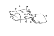
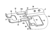
- the hanging metal fitting 32 is an integrated structure that has been subjected to sheet metal pressing, and includes a connecting portion 33, a first fixing portion 34, and a second fixing portion 35.
- the connecting portion 33 has, for example, a rectangular plate shape, and projects horizontally from the corner portion of the top plate 6 toward the outside along the width direction of the unit body 5.
- a through hole 36 through which the suspension bolt 31 passes and a slit-shaped guide passage 37 that connects the front end edge of the connecting part 33 and the through hole 36 are formed at the front end of the connecting part 33.
- the through hole 36 has an elongated hole shape along the width direction of the connecting portion 33.
- the guide passage 37 is an element for guiding the lower end portion of the suspension bolt 31 to the through hole 36, and has a shape that gradually expands from the through hole 36 toward the tip edge of the connecting portion 33.
- the first fixed portion 34 is bent at a substantially right angle from the end opposite to the tip of the connecting portion 33. In other words, the connecting portion 33 and the first fixing portion 34 are maintained in a positional relationship that is substantially orthogonal.
- the first fixing portion 34 is overlapped with the inner surface of the side plate portion 6 b at the corner portion of the top plate 6. According to the present embodiment, one through hole 39 is formed in the region of the side plate portion 6b where the first fixing portion 34 is overlapped. Furthermore, one screw hole 40 that matches the through hole 39 is formed in the first fixing portion 34.
- the second fixing portion 35 has, for example, a square plate shape, and is integrally extended from the tip of the first fixing portion 34 along the lower surface of the upper plate portion 6a of the top plate 6. For this reason, the second fixing portion 35 extends horizontally toward the opposite side of the connecting portion 33 with respect to the first fixing portion 34.
- the hanging metal fitting 32 of the present embodiment has a through hole 41 and a pair of reinforcing portions 42a and 42b.
- the through hole 41 is formed at the end of the connecting portion 33 adjacent to the first fixing portion 34 and is adjacent to the screw hole 40 formed in the first fixing portion 34.
- the through hole 41 has, for example, a square opening shape.
- the reinforcing portions 42a and 42b are configured by drawing the both side edges along the width direction of the hanging bracket 32.
- the reinforcing portions 42 a and 42 b are continuously formed in a region from the intermediate portion of the connecting portion 33 to the intermediate portion of the second fixing portion 35 via the first fixing portion 34. Therefore, the through hole 39 and the through hole 41 are located between the reinforcing portions 42a and 42b.
- the hanging metal fitting 32 of the present embodiment has an inclined portion 38 between the first fixing portion 34 and the second fixing portion 35.
- concave portions 45 are formed at the four corners of the top plate 6, respectively.
- the concave portion 45 is configured by, for example, drawing the upper plate portion 6a of the top plate 6.
- the concave portion 45 projects downward from the upper plate portion 6 a and has a shape that matches the tip of the second fixing portion 35 of the hanging bracket 32.
- the recess 45 includes a slit-shaped opening 45a and a flat bottom surface 45b.
- the opening 45a is an element into which the second fixing portion 35 of the hanging metal fitting 32 is inserted, and is opened toward the side plate portion 6b in which the through hole 39 is opened.
- the bottom surface 45b is formed continuously with the opening 45a, and the tip of the second fixing portion 35 overlaps the bottom surface 45b.
- each hanging bracket 32 is fixed to the top plate 6 through a single fixing screw 47 in a state where the second fixing portion 35 is inserted into the opening 45 a of the recess 45.
- the fixing screw 47 is an example of a fastener.
- the tip end portion of the second fixing portion 35 advances onto the bottom surface 45 a of the recess 45.
- the outer peripheral edge of the distal end portion of the second fixing portion 35 is surrounded by the edge of the recess 45. In other words, the distal end portion of the second fixing portion 35 is fitted into the recess 45.
- the fixing screw 47 is screwed into the screw hole 40 of the hanging bracket 32 from the outside along the width direction of the top plate 6 through the through hole 39 of the side plate portion 6b.
- the first fixing portion 34 of the hanging bracket 32 is closely attached to the inner surface of the side plate portion 6 b of the top plate 6 without a gap, and the hanging bracket 32 is fixed to the four corners of the top plate 6.
- the head 47 a of the fixing screw 47 protrudes from the outer surface of the side plate portion 6 b of the top plate 6.
- the top plate 6 is turned upside down, and the top plate 6 is held horizontally with the lower surface of the upper plate portion 6a facing upward. Thereafter, the distal end portion of the second fixing portion 35 of the hanging metal fitting 32 is fitted into the concave portion 45 from the lower surface side of the upper plate portion 6a through the opening 45a. As a result, the tip of the second fixing portion 35 is surrounded by the edge of the recess 45 and overlaps the bottom surface 45 b of the recess 45.
- the hanging bracket 32 is opened so that the inclined portion 38 avoids the side plate portion 6b. It can be advanced in the direction of the part 45a. Therefore, the suspension fitting 32 is not obstructed by the side plate portion 6b, and the second fixing portion 35 of the suspension fitting 32 can be smoothly fitted into the recess 45.
- the fixing screw 47 is screwed into the screw hole 40 of the hanging bracket 32 from the outside along the width direction of the top plate 6 through the through hole 39 of the side plate portion 6b.
- the connecting portion 33 of the hanging bracket 32 projects horizontally toward the outside along the width direction of the top plate 6 through the side plate portion 6 b.
- the through hole 39 opened in the side plate portion 6 b is hidden under the connecting portion 33.
- the through hole 41 is formed at the end of the connecting portion 33 adjacent to the first fixing portion 34, the operator visually observes the position of the through hole 39 through the through hole 41. Can do.
- the fixing screw 47 can be screwed into the screw hole 40 from the through hole 41 while confirming the positional relationship between the fixing screw 47 and the through hole 39 with the naked eye.
- the fixing screw 47 is tightened, the first fixing portion 34 of the hanging bracket 32 comes into close contact with the inner surface of the side plate portion 6b of the top plate 6, and the position of the hanging bracket 32 with respect to the top plate 6 is fixedly determined.
- the hanging bracket 32 fixed to one end of the top plate 6 passes through a pair of slits 50 a and 50 b whose connecting portion 33 is formed in the upper portion of the first side plate 7.
- the first side plate 7 protrudes outward.
- the hanging metal fitting 32 fixed to the other end of the top plate 6 has a connecting portion 33 through a pair of slits (not shown) formed in the upper part of the second side plate 8. It protrudes outward.
- a pair of bulging portions 51 a and 51 b are formed on the first side plate 7.
- the bulging portions 51 a and 51 b are adjacent to the slits 50 a and 50 b and project outside the first side plate 7 so as to cover the head 47 a of the fixing screw 47.
- the bulging portions 51a and 51b prevent the fixing screw 47 from loosening or falling off by approaching or contacting the head 47a of the fixing screw 47, for example.
- the bulging portions 51a and 51b are formed on the second side plate 8 in the same manner, but are not shown in the present embodiment.
- the lower ends of the four suspension bolts 31 suspended from the beam 2 are guided to the through hole 36 through the guide passage 37 of the suspension fitting 32.
- a pair of nuts 54a and 54b are screwed into the lower end of each suspension bolt 31 via a pair of washers 53a and 53b.
- the nuts 54a and 54b sandwich the connecting portion 33 of the hanging bracket 32 in cooperation with the washers 53a and 53b.
- FIG. 13 discloses the relative positional relationship between the top plate 6 and the hanging bracket 32 when the indoor unit 1 is suspended from the ceiling space 4. As indicated by an arrow in FIG. 13, in the state where the indoor unit 1 is suspended from the ceiling space 4, a downward load is applied to the suspension fitting 32.
- the second fixing portion 32 of the hanging bracket 32 is located below the upper plate portion 6a of the top plate 6, but the tip end portion of the second fixing portion 32 is formed on the upper plate portion 6a. It overlaps on the bottom surface 45 b of the recessed portion 45. For this reason, the downward load applied to the hanging bracket 32 can be positively received by the strong top plate 6 constituting the unit body 5.
- the indoor unit 1 can be held in the ceiling space 4 in a stable posture, and an air conditioner having high reliability in terms of strength can be obtained.
- the second fixing portion 35 of the hanging bracket 32 fits into the recess 45 of the top plate 6, the relative position between the top plate 6 and the hanging bracket 32 is easily determined. In other words, alignment between the screw hole 40 of the hanging bracket 32 and the through hole 39 of the top plate 6 can be easily performed.
- the operator can tighten the fixing screw 47 while confirming the position of the through hole 40 and the fixing screw 47 with the naked eye through the through hole 41. it can.
- the hanging bracket 32 is fixed to a fixed position of the top plate 6 with a single fixing screw 47 so as not to move. can do. That is, the presence of the recess 45 can prevent the hanging bracket 32 from rotating about the fixing screw 47 as a fulcrum. As a result, the number of parts of the unit body 5 can be reduced, and there is an advantage that the unit body 5 can be reduced in weight and cost.
- the hanging metal fittings 32 are fixed to the four corners of the top plate 6. However, for example, two hanging metal fittings 32 are added to the middle portion along the width direction of the top plate 6, so You may make it suspend from the ceiling space 4 at several places.
- the upper structure to which the hanging bracket is fixed is not limited to the top plate.
- the cross member may be used as an upper structure, and a hanging bracket may be fixed to the cross member. Good.
- FIG. 16 discloses a second embodiment.
- the second embodiment is different from the first embodiment in the position of the inlet of the unit body.
- the other configuration of the unit body is the same as that of the first embodiment. Therefore, in the second embodiment, the same components as those in the first embodiment are denoted by the same reference numerals, and the description thereof is omitted.
- a region surrounded by the rear edge, the rear edge of the first side plate 7 and the rear edge of the second side plate 8 functions as a suction port.
- the suction duct 61 is connected to the region of the unit body 5.
- the suction duct 61 is led behind the unit body 5 through the ceiling space 4 and communicated with an air intake (not shown) provided in the building.
- FIG. 17 discloses a third embodiment.
- the third embodiment is different from the first embodiment in the configuration for receiving the load applied to the hanging bracket by the upper plate portion of the top plate.
- the configuration of the other indoor units is the same as that of the first embodiment. Therefore, in the third embodiment, the same components as those in the first embodiment are denoted by the same reference numerals, and the description thereof is omitted.
- the upper plate portion 6a of the top plate 6 has openings 71 at the corners thereof.
- the opening portion 71 has a slit-like opening shape extending in the depth direction of the upper plate portion 6a.
- the second fixing portion 35 of the hanging bracket 32 includes a first portion 72 that overlaps the lower surface of the upper plate portion 6a, a second portion 73 that overlaps the upper surface of the upper plate portion 6a, and a first portion 72. And a third portion 74 positioned between the second portion 73 and the second portion 73.
- the first portion 72 and the second portion 73 are shifted from each other in the thickness direction of the second fixing portion 35.
- a step b along the thickness direction of the second fixing portion 35 is formed between the first portion 72 and the second portion 73.
- the third portion 74 is raised obliquely from the first portion 72 toward the second portion 73.
- the tip of the second portion 73 of the second fixing portion 35 is moved from the lower surface side of the upper plate portion 6a to the upper plate portion 6a. Is inserted into the opening 71. As a result, the second fixing portion 73 is exposed on the upper plate portion 6 a and the third portion 74 is guided to the opening 71. As a result, the first portion 72 contacts the lower surface of the upper plate portion 6a, and the second portion 73 overlaps the upper surface of the upper plate portion 6a.
- one fixing screw 47 is screwed into the screw hole 40 of the hanging bracket 32 from the outside along the width direction of the top plate 6 through the through hole 39 of the side plate portion 6b.
- the fixing screw 47 is tightened, the first fixing portion 34 of the hanging bracket 32 comes into close contact with the inner surface of the side plate portion 6b of the top plate 6, and the position of the hanging bracket 32 with respect to the top plate 6 is fixedly determined.
- the second fixing portion 32 of the hanging bracket 32 has the second portion 73 that overlaps the upper surface of the upper plate portion 6a of the top plate 6. For this reason, when the indoor unit 1 is suspended in the ceiling space 4, the downward load applied to the hanging bracket 32 can be positively received by the strong top plate 6 of the unit body 5.
- the indoor unit 1 can be suspended in a stable posture, and an air conditioner having high reliability in terms of strength can be obtained.
- SYMBOLS 4 Ceiling space, 5 ... Unit main body, 6 ... Upper structure (top plate), 21 ... Blower, 22 ... Indoor heat exchanger, 31 ... Suspension tool (hanging bolt), 32 ... Suspension metal fitting, 33 ... Connection part, 34 ... 1st fixing
Landscapes
- Engineering & Computer Science (AREA)
- Chemical & Material Sciences (AREA)
- Combustion & Propulsion (AREA)
- Mechanical Engineering (AREA)
- General Engineering & Computer Science (AREA)
- Air Filters, Heat-Exchange Apparatuses, And Housings Of Air-Conditioning Units (AREA)
- Supports For Pipes And Cables (AREA)
- Duct Arrangements (AREA)
Abstract
空気調和機は、建屋の天井空間(4)に複数の吊り具(31)を介して吊り下げられ、室内熱交換器(22)および送風機(21)を収容したユニット本体(5)と、前記ユニット本体(5)の上部を構成する上部構造体(6)に設けられ、前記吊り具(31)の下端部が連結された複数の吊金具(32)と、を備えている。前記上部構造体(6)は、水平方向に延びた上板部(6a)を含んでいる。前記吊金具(32)は、前記吊り具(31)が連結された連結部(33)と、前記上部構造体(6)に重ねた状態で当該上部構造体(6)に締結具(47)を介して固定された第1の固定部(34)と、前記第1の固定部(34)から一体に延出され、前記上板部(6a)に対し上方から重なり合うように構成された第2の固定部(35)と、を備えている。
Description
本発明の実施形態は、例えば天井吊り下げ形の室内ユニットを備えた空気調和機に関する。
送風機および室内熱交換器を収容した室内ユニットが天井裏に配置された空気調和機では、室内ユニットが例えば複数の吊りボルトを介して天井裏の梁等から吊り下げられている。この種の空気調和機によると、室内ユニットの外郭を構成するユニット本体の側面に複数の吊金具がねじで固定されている。吊金具は、ユニット本体の側面から四方に水平に突出されており、当該吊金具の先端部に吊りボルトの下端部が連結されている。
吊金具がユニット本体の側面にねじで固定された従来の空気調和機では、吊金具に加わる荷重をユニット本体で積極的に受け止めることができない。この結果、室内ユニットの重量の多くが吊金具およびユニット本体の側面に集中して加わり、強度的な面で改善の余地が残されている。
本実施形態の空気調和機は、建屋の天井空間に複数の吊り具を介して吊り下げられ、室内熱交換器および当該熱交換器に空気を送る送風機を収容したユニット本体と、前記ユニット本体の上部を構成する上部構造体に設けられ、前記吊り具の下端部が連結された複数の吊金具と、を備えている。前記上部構造体は、水平方向に延びた上板部を含んでいる。前記吊金具は、前記吊り具が連結された連結部と、前記上部構造体に重ねた状態で当該上部構造体に締結具を介して固定された第1の固定部と、前記第1の固定部から一体に延出され、前記上板部に対し上方から重なり合うように構成された第2の固定部と、を備えている。
[第1の実施形態]
以下、第1の実施形態について図1ないし図15を参照して説明する。
以下、第1の実施形態について図1ないし図15を参照して説明する。
図1は、空気調和機の室内ユニットを天井裏の空間に据え付けた状態を模式的に示す側面図、図2は、室内ユニットの斜視図である。
図1に示すように、室内ユニット1は、例えば建屋の天井裏に据え付けられている。本実施形態では、天井裏とは建屋の梁2と天井板3との間に規定された天井空間4のことを指している。
図2ないし図6に示すように、室内ユニット1は、幅寸法W、奥行寸法Dおよび厚さ寸法Hを有する四角い偏平な箱形である。室内ユニット1の幅寸法Wは、奥行寸法Dよりも大きく形成されているとともに、厚さ寸法Hが幅寸法Wおよび奥行寸法Dよりも十分に小さく形成されている。
室内ユニット1は、金属製のユニット本体5を備えている。ユニット本体5は、室内ユニット1の外郭を構成する要素であって、天板6、第1の側板7、第2の側板8、底板9、フロント枠10、背板11および仕切り板12を備えている。
天板6は、ユニット本体5の上部を構成する上部構造体の一例である。図7に示すように、天板6は、水平方向に延びた上板部6aと、上板部6aの周縁に連なる側板部6bと、を有している。側板部6bは、上板部6aの周縁から下向きに略直角に折り曲げられている。側板部6bは、フランジ部と言い換えることができる。
第1の側板7は、天板6の幅方向に沿う一端部に位置されている。第1の側板7は、その上端部が天板6の側板部6bの外面に複数のねじで固定されているとともに、天板6の一端部から下向きに延びている。第2の側板8は、天板6の幅方向に沿う他端部に位置されている。第2の側板8は、その上端部が天板6の側板部6bの外面に複数のねじで固定されているとともに、天板6の他端部から下向きに延びている。このため、第1の側板7および第2の側板8は、天板6の幅方向に互いに間隔を存して向かい合っている。
底板9は、第1の側板7の下端部と第2の側板8の下端部との間に跨るようにフロント枠10および仕切り板12に固定されて、ユニット本体5の底を構成している。底板9は、ユニット本体5の奥行き方向に沿う長さの略半分程度の大きさを有している。したがって、ユニット本体5の底のうち底板9から外れた領域は、細長い吸込口14を構成している。吸込口14は、天井板3に設けた吸込みグリル15と向かい合っている。
フロント枠10は、天板6の前縁、第1の側板7の前縁および第2の側板8の前縁に複数のねじで固定されている。フロント枠10は、ユニット本体5の前端に細長い吹出し口16を構成している。図1に示すように、吹出しダクト17が吹出し口16に接続されている。吹出しダクト17は、天井空間4に配置されているとともに、天井板3に設けた吹出しグリル(図示せず)に接続されている。
背板11は、天板6の後縁、第1の側板7の後縁および第2の側板8の後縁に複数のねじで取り外し可能に固定されている。背板11は、前記吸込口14に対応する大きさを有している。そのため、背板11は、天板6の後縁、第1の側板7の後縁および第2の側板8の後縁から取り外した後に、吸込口14を覆うようにユニット本体5の底に複数のねじで固定することができる。背板11をユニット本体5の底に固定した状態では、天板6の後縁、第1の側板7の後縁および第2の側板8の後縁で囲まれた領域が吸込口として機能する。
図3および図4に示すように、仕切り板12は、吸込口14の一側縁に沿って起立されている。仕切り板12の周縁部は、天板6の下面、第1の側板7の内面および第2の側板8の内面に突き合わされている。このため、仕切り板12は、ユニット本体5の内部を送風室18と熱交換室19との二室に区画している。
送風室18は、前記吸込口14を有するとともに、当該送風室18に送風機21が収容されている。熱交換室19は、前記吹出し口16を有するとともに、当該熱交換室19に室内熱交換器22およびドレンパン23が配置されている。
図3に示すように、送風機21は、ファンモータ25および一対のファン26a,26bを備えている。ファンモータ25は、その両側面から同軸状に突出された二本の回転軸27a,27bを有し、各回転軸27a,27bにファン26a,26bが取り付けられている。ファン26a,26bは、夫々ファンケース28a,28bで取り囲まれている。ファンケース28a,28bは、ノズル部29a,29bを一体に有している。ノズル部29a,29bは、仕切り板12を貫通して熱交換室19に開口されている。
図4に示すように、室内熱交換器22は、室内ユニット1の厚さ寸法が制限されているため、強く前傾された姿勢で熱交換室19に収容されている。室内熱交換器22は、ユニット本体5の幅方向に延びているとともに、その両端部が夫々側部断熱材(図示せず)を介してユニット本体5に支持されている。さらに、室内熱交換器22の上端部は、上部断熱材30によって支持されている。上部断熱材30は、室内熱交換器22の上端部と天板6との間に介在されている。側部断熱材および上部断熱材30は、室内熱交換器22の冷凍サイクル作用に伴う発熱がユニット本体5に伝わるのを抑制する。
ドレンパン23は、室内熱交換器22の下方に配置されている。ドレンパン23は、例えば発泡スチロールのような断熱材で構成されている。ドレンパン23は、室内熱交換器22を下方から支えているとともに、室内熱交換器22から滴下するドレン水を受け止める。
ファンモータ25によりファン26a,26bが回転されると、ファン26a,26bは、軸方向から空気を吸い込むとともに、吸い込んだ空気をファン26a,26bの外周面からファンケース28a,28bの内側に吐き出す。このため、図1および図4に矢印で示すように、建屋の室内の空気が天井板3の吸込みグリル15からユニット本体5の吸込口14を通じて送風室18に吸い込まれる。送風室18に吸い込まれた空気は、ファンケース28a,28bのノズル部29a,29bから室内熱交換器22に向けて吹き出す。
室内熱交換器22は、ノズル部29a,29bから吹き出す空気との熱交換により、当該空気を冷気もしくは暖気の熱交換空気に変える。熱交換空気は、吹出し口16から吹出しダクト17を通じて室内に送出される。これにより、室内の冷房又は暖房が実行される。
図1、図5および図6に示すように、送風機21および室内熱交換器22を収容したユニット本体5は、天井空間4に位置するように例えば四本の吊りボルト31を介して建屋の梁2から吊り下げられている。具体的には、ユニット本体5の天板6に四つの吊金具32が固定されている。吊金具32は、吊り具の一例である前記吊りボルト31が連結される要素であって、互いに共通の構成を有している。
図8および図13に示すように、吊金具32は、板金プレス加工された一体構造物であり、連結部33、第1の固定部34および第2の固定部35を有している。連結部33は、例えば長方形の板状であり、天板6の角部からユニット本体5の幅方向に沿う外側に向けて水平に張り出している。
連結部33の先端部には、吊りボルト31が通る貫通孔36と、連結部33の先端縁と貫通孔36との間を結ぶスリット状のガイド通路37と、が形成されている。貫通孔36は、連結部33の幅方向に沿う長孔状の開口形状を有している。ガイド通路37は、吊りボルト31の下端部を貫通孔36に導くための要素であって、貫通孔36から連結部33の先端縁に向けて次第に拡開するような形状を有している。
第1の固定部34は、連結部33の先端部とは反対側の端部から略直角に折り曲げられている。言い換えると、連結部33と第1の固定部34とは、略直交するような位置関係に保たれている。第1の固定部34は、天板6の角部において側板部6bの内面に重ね合わされている。本実施形態によると、側板部6bのうち第1の固定部34が重ね合わされる領域に一つの通孔39が形成されている。さらに、第1の固定部34には、通孔39に合致する一つのねじ孔40が形成されている。
第2の固定部35は、例えば四角い板状であり、天板6の上板部6aの下面に沿うように第1の固定部34の先端から一体に延出されている。このため、第2の固定部35は、第1の固定部34に対し連結部33の反対側に向けて水平に張り出している。
加えて、本実施形態の吊金具32は、貫通孔41および一対の補強部42a,42bを有している。貫通孔41は、第1の固定部34に隣接した連結部33の端部に形成されているとともに、第1の固定部34に形成したねじ孔40と隣り合っている。貫通孔41は、例えば四角い開口形状を有している。
補強部42a,42bは、吊金具32の幅方向に沿う両側縁部に絞り加工を施すことで構成されている。補強部42a,42bは、連結部33の中間部から第1の固定部34を経由して第2の固定部35の中間部に至る領域に連続して形成されている。そのため、通孔39および貫通孔41は、補強部42a,42bの間に位置されている。
さらに、本実施形態の吊金具32は、第1の固定部34と第2の固定部35との間に傾斜部38を有している。
一方、図7に示すように、天板6の四つの角部には、夫々凹部45が形成されている。凹部45は、天板6の上板部6aに例えば絞り加工を施すことで構成されている。図9ないし図11に示すように、凹部45は、上板部6aから下向きに張り出すとともに、吊金具32の第2の固定部35の先端部に合致した形状を有している。
凹部45は、スリット状の開口部45aと、平坦な底面45bと、を備えている。開口部45aは、吊金具32の第2の固定部35が挿入される要素であって、通孔39が開口された側板部6bに向けて開口されている。底面45bは、開口部45aに連続して形成されており、当該底面45bの上に第2の固定部35の先端部が重なり合うようになっている。
図11ないし図13に示すように、各吊金具32は、第2の固定部35を凹部45の開口部45aに挿入した状態で、一本の固定ねじ47を介して天板6に固定されている。固定ねじ47は、締結具の一例である。第2の固定部35を開口部45aに挿入すると、第2の固定部35の先端部が凹部45の底面45aの上に進出する。さらに、第2の固定部35の先端部の外周縁が凹部45の縁によって取り囲まれる。言い換えると、第2の固定部35の先端部が凹部45に嵌り込む。
固定ねじ47は、天板6の幅方向に沿う外側から側板部6bの通孔39を通じて吊金具32のねじ孔40にねじ込まれている。このねじ込みにより、吊金具32の第1の固定部34が天板6の側板部6bの内面に隙間なく密着し、吊金具32が天板6の四つの角部に固定される。吊金具32が天板6に固定された状態では、固定ねじ47の頭部47aが天板6の側板部6bの外面から突出されている。
次に、吊金具32を天板6に固定する手順について説明する。
最初に、図7に示すように天板6を上下に反転させ、その上板部6aの下面が上を向いた姿勢に天板6を水平に保持する。この後、吊金具32の第2の固定部35の先端部を上板部6aの下面の側から開口部45aを通じて凹部45に嵌め込む。この結果、第2の固定部35の先端部が凹部45の縁で囲まれるとともに、凹部45の底面45bと重なり合う。
この際、吊金具32の第1の固定部34と第2の固定部35との間に傾斜部38を設けたことにより、傾斜部38が側板部6bを避けるようにして吊金具32を開口部45aの方向に進ませることができる。そのため、吊金具32が側板部6bに邪魔されることはなく、当該吊金具32の第2の固定部35を滑らかに凹部45に嵌め込むことができる。
引き続いて、固定ねじ47を天板6の幅方向に沿う外側から側板部6bの通孔39を通じて吊金具32のねじ孔40にねじ込む。この際、図10ないし図12に最もよく示されるように、吊金具32の連結部33が側板部6bの上方を通って天板6の幅方向に沿う外側に向けて水平に張り出しているので、側板部6bに開口された通孔39が連結部33の下に隠れてしまう。
しかるに、本実施形態では、第1の固定部34に隣接した連結部33の端部に貫通孔41が形成されているので、作業者は、貫通孔41を通じて通孔39の位置を目視することができる。この結果、貫通孔41から固定ねじ47と通孔39との位置関係を肉眼で確認しながら固定ねじ47をねじ孔40にねじ込むことができる。固定ねじ47を締め付けると、吊金具32の第1の固定部34が天板6の側板部6bの内面に密着し、天板6に対する吊金具32の位置が固定的に定まる。
図14および図15に示すように、天板6の一方の端部に固定された吊金具32は、その連結部33が第1の側板7の上部に形成された一対のスリット50a,50bを通して第1の側板7の外側方に突出されている。同様に、天板6の他方の端部に固定された吊金具32は、その連結部33が第2の側板8の上部に形成された一対のスリット(図示せず)を通して第2の側板8の外側方に突出されている。
さらに、第1の側板7に一対の膨出部51a,51bが形成されている。膨出部51a,51bは、スリット50a,50bに隣接するとともに、固定ねじ47の頭部47aを覆うように第1の側板7の外側に張り出している。膨出部51a,51bは、例えば固定ねじ47の頭部47aに近接もしくは接触することで、固定ねじ47が緩んだり脱落するのを防いでいる。膨出部51a,51bは、第2の側板8にも同様に形成されているが、本実施形態では図示を省略する。
梁2から垂下された四本の吊りボルト31の下端部は、吊金具32のガイド通路37を通じて貫通孔36に導かれている。図13に示すように、各吊りボルト31の下端部には、一対のワッシャ53a,53bを介して一対のナット54a,54bがねじ込まれている。ナット54a,54bは、ワッシャ53a,53bと協働して吊金具32の連結部33を挟み込んでいる。これにより、吊りボルト31の下端部が吊金具32に連結され、ユニット本体5が水平な姿勢で天井空間4に吊り下げられている。
図13は、室内ユニット1が天井空間4に吊り下げられた時の天板6と吊金具32との相対的な位置関係を開示している。図13に矢印で示すように、室内ユニット1が天井空間4に吊り下げられた状態では、吊金具32に下向きの荷重が加わる。
この際、吊金具32の第2の固定部32は、天板6の上板部6aの下側に位置されてはいるものの、第2の固定部32の先端部が上板部6aに形成した凹部45の底面45bの上に重なり合っている。このため、吊金具32に加わる下向きの荷重を、ユニット本体5を構成する丈夫な天板6で積極的に受け止めることができる。
この結果、吊金具32および固定ねじ47が荷担すべき荷重が軽減され、室内ユニット1を吊り下げる吊金具32の回りの強度を十分に確保することができる。よって、室内ユニット1を安定した姿勢で天井空間4に保持することができ、強度的な面で信頼性の高い空気調和機を得ることができる。
さらに、吊金具32の第2の固定部35が天板6の凹部45に嵌り込むので、天板6と吊金具32との相対的な位置が簡単に定まる。言い換えると、吊金具32のねじ孔40と天板6の通孔39との間の位置合わせを容易に行うことができる。
加えて、吊金具32の連結部33に貫通孔41を設けたことで、作業者は、貫通孔41を通じて通孔40と固定ねじ47の位置を肉眼で確認しながら固定ねじ47を締め付けることができる。
したがって、吊金具32を固定ねじ47で天板6に固定する際の作業性が向上し、製造性に優れた空気調和機を提供することができる。
それとともに、天板6に吊金具32の第2の固定部35が嵌り込む凹部45を設けたことで、一本の固定ねじ47で吊金具32を天板6の定位置に移動不能に固定することができる。すなわち、凹部45の存在により、吊金具32が固定ねじ47を支点として回動しようとするのを防止できる。この結果、ユニット本体5の部品点数を削減することができ、ユニット本体5の軽量化やコストの低減に寄与するといった利点がある。
第1の実施形態では、天板6の四つの角部に吊金具32を固定したが、例えば天板6の幅方向に沿う中間部に二つの吊金具32を増設し、ユニット本体5を六ヶ所で天井空間4に吊り下げるようにしてもよい。
さらに、吊金具が固定される上部構造体は天板に限らない。例えばユニット本体の幅方向に沿う両端部に天板を下から支えるクロスメンバが存在するようなユニット本体では、前記クロスメンバを上部構造体として、当該クロスメンバに吊金具を固定するようにしてもよい。
[第2の実施形態]
図16は、第2の実施形態を開示している。第2の実施形態は、ユニット本体の吸込口の位置が第1の実施形態と相違している。それ以外のユニット本体の構成は、第1の実施形態と同様である。そのため、第2の実施形態において、第1の実施形態と同一の構成部分には同一の参照符号を付して、その説明を省略する。
図16は、第2の実施形態を開示している。第2の実施形態は、ユニット本体の吸込口の位置が第1の実施形態と相違している。それ以外のユニット本体の構成は、第1の実施形態と同様である。そのため、第2の実施形態において、第1の実施形態と同一の構成部分には同一の参照符号を付して、その説明を省略する。
図4に二点鎖線で示すように、ユニット本体5の底に開口された吸込口14を背板11で覆った室内ユニット1では、第1の実施形態で述べたように、天板6の後縁、第1の側板7の後縁および第2の側板8の後縁で囲まれた領域が吸込口として機能する。
したがって、この種の室内ユニット1にあっては、ユニット本体5の前記領域に吸込みダクト61が接続されている。吸込みダクト61は、天井空間4を通してユニット本体5の背後に導かれているとともに、建屋に設けた図示しない空気取り入れ口に連通されている。
[第3の実施形態]
図17は、第3の実施形態を開示している。第3の実施形態は、吊金具に加わる荷重を天板の上板部で受け止めるための構成が第1の実施形態と相違している。それ以外の室内ユニットの構成は第1の実施形態と同様である。そのため、第3の実施形態において、第1の実施形態と同一の構成部分には同一の参照符号を付して、その説明を省略する。
図17は、第3の実施形態を開示している。第3の実施形態は、吊金具に加わる荷重を天板の上板部で受け止めるための構成が第1の実施形態と相違している。それ以外の室内ユニットの構成は第1の実施形態と同様である。そのため、第3の実施形態において、第1の実施形態と同一の構成部分には同一の参照符号を付して、その説明を省略する。
図17に示すように、天板6の上板部6aは、その角部に開口部71を有している。開口部71は、上板部6aの奥行き方向に延びるスリット状の開口形状を有している。一方、吊金具32の第2の固定部35は、上板部6aの下面に重なり合う第1の部分72と、上板部6aの上面に重なり合う第2の部分73と、第1の部分72と第2の部分73との間に位置された第3の部分74と、を有している。
第1の部分72と第2の部分73とは、第2の固定部35の厚さ方向に互いにずれている。言い換えると、第1の部分72と第2の部分73との間に第2の固定部35の厚さ方向に沿う段差bが形成されている。第3の部分74は、第1の部分72から第2の部分73に向けて斜めに立ち上げられている。
第3の実施形態において、吊金具32を天板6に固定するには、最初に第2の固定部35の第2の部分73の先端を上板部6aの下面の側から上板部6aの開口部71に差し込む。これにより、第2の固定部73を上板部6aの上に露出させるとともに、第3の部分74を開口部71に導く。この結果、第1の部分72が上板部6aの下面に接触し、第2の部分73が上板部6aの上面に重なり合う。
引き続いて、一本の固定ねじ47を天板6の幅方向に沿う外側から側板部6bの通孔39を通じて吊金具32のねじ孔40にねじ込む。固定ねじ47を締め付けると、吊金具32の第1の固定部34が天板6の側板部6bの内面に密着し、天板6に対する吊金具32の位置が固定的に定まる。
第3の実施形態によると、吊金具32の第2の固定部32は、天板6の上板部6aの上面に重なり合う第2の部分73を有している。このため、室内ユニット1を天井空間4に吊り下げた時に、吊金具32に加わる下向きの荷重をユニット本体5の丈夫な天板6で積極的に受け止めることができる。
したがって、吊金具32および固定ねじ47が荷担すべき荷重が軽減され、室内ユニット1を吊り下げる吊金具32の回りの強度を十分に確保することができる。よって、第1の実施形態と同様に、室内ユニット1を安定した姿勢で吊り下げることができ、強度的な面で信頼性の高い空気調和機を得ることができる。
4…天井空間、5…ユニット本体、6…上部構造体(天板)、21…送風機、22…室内熱交換器、31…吊り具(吊りボルト)、32…吊金具、33…連結部、34…第1の固定部、35…第2の固定部、47…締結具(固定ねじ)。
Claims (9)
- 建屋の天井空間に複数の吊り具を介して吊り下げられ、室内熱交換器および当該熱交換器に空気を送る送風機を収容したユニット本体と、
前記ユニット本体の上部を構成する上部構造体に設けられ、前記吊り具の下端部が連結された複数の吊金具と、を具備した空気調和機であって、
前記上部構造体は、水平方向に延びた上板部を含み、
前記吊金具は、前記吊り具が連結された連結部と、前記上部構造体に重ねた状態で当該上部構造体に締結具を介して固定された第1の固定部と、前記第1の固定部から一体に延出され、前記上板部に対し上方から重なり合うように構成された第2の固定部と、を備えた空気調和機。 - 前記上部構造体は、前記上板部の周縁に連なる側板部を含み、前記第1の固定部が前記側板部に固定された請求項1に記載の空気調和機。
- 前記吊金具の前記連結部と前記第1の固定部とは、互いに交差するような位置関係を有するとともに、前記連結部に前記側板部の前記通孔と隣り合う貫通孔が形成された請求項2に記載の空気調和機。
- 前記締結具はねじであり、前記上部構造体は、前記ねじが通る通孔を有し、前記吊金具の前記第1の固定部は、前記通孔が合致するとともに前記ねじがねじ込まれるねじ孔を有する請求項1ないし請求項3のいずれか一項に記載の空気調和機。
- 前記上部構造体の前記上板部は、下向きに張り出す凹部を含み、当該凹部の一端に前記吊金具の前記第2の固定部が挿入される開口部が形成されているとともに、前記第2の固定部が前記凹部の底の上に重ねられた請求項1ないし請求項4のいずれか一項に記載の空気調和機。
- 前記凹部は、前記第2の固定部が嵌り込む形状を有する請求項1ないし請求項5のいずれか一項に記載の空気調和機。
- 前記上部構造体の前記上板部は、前記凹部の前記開口部に連続する下面を有し、前記第2の固定部が前記凹部の前記下面に重ねられた請求項1ないし請求項6のいずれか一項に記載の空気調和機。
- 前記上部構造体の前記上板部は、前記第2の固定部が挿入される開口部を有し、前記第2の固定部は、前記上板部の下面に重なり合う第1の部分と、前記上板部の上面に重なり合う第2の部分と、前記第1の部分と前記第2の部分との間を結ぶように前記開口部を通過する第3の部分と、を有する請求項1ないし請求項4のいずれか一項に記載の空気調和機。
- 前記第1の部分と前記第2の部分との間に、前記第2の固定部の厚さ方向に沿う段差が形成された請求項8に記載の空気調和機。
Priority Applications (4)
| Application Number | Priority Date | Filing Date | Title |
|---|---|---|---|
| EP13899418.1A EP3091304B1 (en) | 2013-12-20 | 2013-12-20 | Air conditioner |
| PCT/JP2013/084273 WO2015092919A1 (ja) | 2013-12-20 | 2013-12-20 | 空気調和機 |
| CN201380080726.4A CN105705880B (zh) | 2013-12-20 | 2013-12-20 | 空调 |
| PL13899418T PL3091304T3 (pl) | 2013-12-20 | 2013-12-20 | Klimatyzator |
Applications Claiming Priority (1)
| Application Number | Priority Date | Filing Date | Title |
|---|---|---|---|
| PCT/JP2013/084273 WO2015092919A1 (ja) | 2013-12-20 | 2013-12-20 | 空気調和機 |
Publications (1)
| Publication Number | Publication Date |
|---|---|
| WO2015092919A1 true WO2015092919A1 (ja) | 2015-06-25 |
Family
ID=53402311
Family Applications (1)
| Application Number | Title | Priority Date | Filing Date |
|---|---|---|---|
| PCT/JP2013/084273 Ceased WO2015092919A1 (ja) | 2013-12-20 | 2013-12-20 | 空気調和機 |
Country Status (4)
| Country | Link |
|---|---|
| EP (1) | EP3091304B1 (ja) |
| CN (1) | CN105705880B (ja) |
| PL (1) | PL3091304T3 (ja) |
| WO (1) | WO2015092919A1 (ja) |
Families Citing this family (4)
| Publication number | Priority date | Publication date | Assignee | Title |
|---|---|---|---|---|
| CN111219783B (zh) * | 2018-11-27 | 2021-06-04 | 宁波奥克斯电气股份有限公司 | 一种壳体连接装置及空调器 |
| CN110057066A (zh) * | 2019-04-08 | 2019-07-26 | 北京安通伟业工程设备有限公司 | 一种用于中央空调水循环系统的气压增压器 |
| CN111609545A (zh) * | 2020-06-01 | 2020-09-01 | 广东美的暖通设备有限公司 | 吊耳、底盘组件和空调器 |
| CN111606192B (zh) * | 2020-06-01 | 2021-12-14 | 广东美的暖通设备有限公司 | 吊耳、底盘组件和空调器 |
Citations (4)
| Publication number | Priority date | Publication date | Assignee | Title |
|---|---|---|---|---|
| JPH0443738U (ja) * | 1990-08-08 | 1992-04-14 | ||
| JPH09222260A (ja) * | 1996-02-15 | 1997-08-26 | Daikin Ind Ltd | 空気調和機のケーシング |
| JP2001133034A (ja) * | 1999-11-10 | 2001-05-18 | Mitsubishi Electric Corp | 空気調和機の係合装置 |
| JP2006343043A (ja) | 2005-06-09 | 2006-12-21 | Toshiba Kyaria Kk | 空気調和装置 |
Family Cites Families (9)
| Publication number | Priority date | Publication date | Assignee | Title |
|---|---|---|---|---|
| JP3080086B2 (ja) * | 1998-12-01 | 2000-08-21 | ダイキン工業株式会社 | 空気調和機の据付具及び据付構造 |
| JP2006250419A (ja) * | 2005-03-10 | 2006-09-21 | Mitsubishi Electric Corp | 天井埋込形空気調和機 |
| JP2006349310A (ja) * | 2005-06-20 | 2006-12-28 | Sanyo Electric Co Ltd | 空気調和機 |
| JP4945357B2 (ja) * | 2007-07-25 | 2012-06-06 | 三洋電機株式会社 | 天井埋込型空気調和装置の室内機 |
| JP2009030829A (ja) * | 2007-07-25 | 2009-02-12 | Sanyo Electric Co Ltd | 空気調和装置 |
| EP2023049B1 (en) * | 2007-07-25 | 2013-10-30 | Sanyo Electric Co., Ltd. | In-ceiling mount type air conditioner and indoor unit thereof |
| JP2009063265A (ja) * | 2007-09-07 | 2009-03-26 | Toshiba Carrier Corp | 天井吊り下げ形空気調和機 |
| JP2009079826A (ja) * | 2007-09-26 | 2009-04-16 | Fujitsu General Ltd | 天井埋込形空気調和機 |
| JP2013117363A (ja) * | 2011-11-01 | 2013-06-13 | Tokkyokiki Corp | 空調機器の脱落防止金具 |
-
2013
- 2013-12-20 EP EP13899418.1A patent/EP3091304B1/en active Active
- 2013-12-20 CN CN201380080726.4A patent/CN105705880B/zh active Active
- 2013-12-20 WO PCT/JP2013/084273 patent/WO2015092919A1/ja not_active Ceased
- 2013-12-20 PL PL13899418T patent/PL3091304T3/pl unknown
Patent Citations (4)
| Publication number | Priority date | Publication date | Assignee | Title |
|---|---|---|---|---|
| JPH0443738U (ja) * | 1990-08-08 | 1992-04-14 | ||
| JPH09222260A (ja) * | 1996-02-15 | 1997-08-26 | Daikin Ind Ltd | 空気調和機のケーシング |
| JP2001133034A (ja) * | 1999-11-10 | 2001-05-18 | Mitsubishi Electric Corp | 空気調和機の係合装置 |
| JP2006343043A (ja) | 2005-06-09 | 2006-12-21 | Toshiba Kyaria Kk | 空気調和装置 |
Also Published As
| Publication number | Publication date |
|---|---|
| CN105705880B (zh) | 2019-03-08 |
| CN105705880A (zh) | 2016-06-22 |
| EP3091304A1 (en) | 2016-11-09 |
| PL3091304T3 (pl) | 2021-04-06 |
| EP3091304B1 (en) | 2020-09-23 |
| EP3091304A4 (en) | 2017-08-30 |
Similar Documents
| Publication | Publication Date | Title |
|---|---|---|
| JP6134855B2 (ja) | 空気調和機 | |
| JP6572382B2 (ja) | 空気調和機および送風装置 | |
| WO2015092919A1 (ja) | 空気調和機 | |
| JP5708237B2 (ja) | 冷凍装置の室外ユニット | |
| CN202630252U (zh) | 天花板嵌入式空调机 | |
| JP6398550B2 (ja) | 天井埋込型空気調和機 | |
| CN104019494B (zh) | 空调机室内机 | |
| JP2013204840A (ja) | 空気調和機の室外機 | |
| JP6123599B2 (ja) | 空気調和機の室外機 | |
| JP2010159909A (ja) | 空気調和装置 | |
| JP6384244B2 (ja) | 天井埋込型空気調和機 | |
| JP6331935B2 (ja) | 天井埋込型空気調和機 | |
| JP6375837B2 (ja) | 天井埋込型空気調和機 | |
| JP7789301B2 (ja) | 空気調和機の室内機 | |
| JP7179173B2 (ja) | 空気調和機の室内機、及び室内機の付加装置 | |
| JP6019217B2 (ja) | 空気調和機 | |
| WO2014156541A1 (ja) | 空気調和機 | |
| JP2016223637A (ja) | ダクト型空気調和機 | |
| JP7381999B2 (ja) | 空気調和機用の風向板 | |
| JP7310512B2 (ja) | 天吊型空気調和機用のテンプレート | |
| WO2017164044A1 (ja) | 空気調和機および吊金具 | |
| JP4215551B2 (ja) | 天井埋込型空気調和機 | |
| JP2004239530A (ja) | 空気調和機 | |
| JP2024142862A (ja) | 空気調和機 | |
| JPWO2019123638A1 (ja) | 空気調和機の室内機 |
Legal Events
| Date | Code | Title | Description |
|---|---|---|---|
| 121 | Ep: the epo has been informed by wipo that ep was designated in this application |
Ref document number: 13899418 Country of ref document: EP Kind code of ref document: A1 |
|
| NENP | Non-entry into the national phase |
Ref country code: DE |
|
| REEP | Request for entry into the european phase |
Ref document number: 2013899418 Country of ref document: EP |
|
| WWE | Wipo information: entry into national phase |
Ref document number: 2013899418 Country of ref document: EP |
|
| NENP | Non-entry into the national phase |
Ref country code: JP |