WO2015093033A1 - 椅子 - Google Patents
椅子 Download PDFInfo
- Publication number
- WO2015093033A1 WO2015093033A1 PCT/JP2014/006231 JP2014006231W WO2015093033A1 WO 2015093033 A1 WO2015093033 A1 WO 2015093033A1 JP 2014006231 W JP2014006231 W JP 2014006231W WO 2015093033 A1 WO2015093033 A1 WO 2015093033A1
- Authority
- WO
- WIPO (PCT)
- Prior art keywords
- pad
- pelvis
- chair
- sitting
- pad member
- Prior art date
- Legal status (The legal status is an assumption and is not a legal conclusion. Google has not performed a legal analysis and makes no representation as to the accuracy of the status listed.)
- Ceased
Links
Images


Classifications
-
- A—HUMAN NECESSITIES
- A47—FURNITURE; DOMESTIC ARTICLES OR APPLIANCES; COFFEE MILLS; SPICE MILLS; SUCTION CLEANERS IN GENERAL
- A47C—CHAIRS; SOFAS; BEDS
- A47C7/00—Parts, details, or accessories of chairs or stools
- A47C7/02—Seat parts
- A47C7/029—Seat parts of non-adjustable shape adapted to a user contour or ergonomic seating positions
-
- A—HUMAN NECESSITIES
- A47—FURNITURE; DOMESTIC ARTICLES OR APPLIANCES; COFFEE MILLS; SPICE MILLS; SUCTION CLEANERS IN GENERAL
- A47C—CHAIRS; SOFAS; BEDS
- A47C7/00—Parts, details, or accessories of chairs or stools
- A47C7/02—Seat parts
- A47C7/14—Seat parts of adjustable shape; elastically mounted ; adaptable to a user contour or ergonomic seating positions
-
- A—HUMAN NECESSITIES
- A47—FURNITURE; DOMESTIC ARTICLES OR APPLIANCES; COFFEE MILLS; SPICE MILLS; SUCTION CLEANERS IN GENERAL
- A47C—CHAIRS; SOFAS; BEDS
- A47C7/00—Parts, details, or accessories of chairs or stools
- A47C7/02—Seat parts
- A47C7/024—Seat parts with double seats
-
- A—HUMAN NECESSITIES
- A47—FURNITURE; DOMESTIC ARTICLES OR APPLIANCES; COFFEE MILLS; SPICE MILLS; SUCTION CLEANERS IN GENERAL
- A47C—CHAIRS; SOFAS; BEDS
- A47C7/00—Parts, details, or accessories of chairs or stools
- A47C7/36—Supports for the head or the back
- A47C7/40—Supports for the head or the back for the back
- A47C7/405—Supports for the head or the back for the back with double backrests
-
- A—HUMAN NECESSITIES
- A61—MEDICAL OR VETERINARY SCIENCE; HYGIENE
- A61F—FILTERS IMPLANTABLE INTO BLOOD VESSELS; PROSTHESES; DEVICES PROVIDING PATENCY TO, OR PREVENTING COLLAPSING OF, TUBULAR STRUCTURES OF THE BODY, e.g. STENTS; ORTHOPAEDIC, NURSING OR CONTRACEPTIVE DEVICES; FOMENTATION; TREATMENT OR PROTECTION OF EYES OR EARS; BANDAGES, DRESSINGS OR ABSORBENT PADS; FIRST-AID KITS
- A61F5/00—Orthopaedic methods or devices for non-surgical treatment of bones or joints; Nursing devices ; Anti-rape devices
- A61F5/01—Orthopaedic devices, e.g. long-term immobilising or pressure directing devices for treating broken or deformed bones such as splints, casts or braces
- A61F5/0193—Apparatus specially adapted for treating hip dislocation; Abduction splints
Definitions
- the present invention relates to a chair, and more particularly to a chair effective for correcting the pelvis and preventing and reducing back pain.
- Cushions that can be inflated by fluid are provided on both the left and right sides of the seat board as chairs effective for pelvic correction and back pain prevention and reduction, and the cushion is inflated by injecting fluid into the cushion to inflate the cushion.
- a chair that is closely attached to the body for example, Patent Document 1.
- the seat plate that handles the buttock is divided into two left and right and each is movable in the left and right directions, and the left and right seat plates are separated from each other by the seating load
- a chair that disperses the pressure acting on the pelvis when seated by moving is known (for example, Patent Documents 2 and 3).
- Conventionally known chairs have a seat plate that handles the buttocks, and supports the upper limb load of a person who is seated with the seat bones supported from below by the seat plate. It acts on the pelvis as a force in the direction of expanding the pelvis to the left and right. For this reason, when sitting on a chair, especially when sitting for a long time, the pelvis spreads, and sitting on the chair causes the right and left unbalance (distortion) and back pain.
- the chair that closes the cushion to the pelvis by inflating the cushion reduces the upper limb load acting on the pelvis as a force in the direction of expanding the pelvis to the left and right when seated, but supports the seat bone from below by the seat plate Since there is no change, it is inevitable that the upper limb load acts on the pelvis as a force in the direction of expanding the pelvis to the left and right when sitting.
- the chair in which the left and right seat plates move away from each other due to the seating load can disperse the pressure acting on the pelvis when seated, but the seat plate supports the seat bones from below, so the upper limb load when sitting is still Cannot be applied to the pelvis as a force in the direction of expanding the pelvis from side to side.
- a pelvic belt is known as an orthosis to prevent the pelvis from expanding by tightening the pelvis.
- the problem to be solved by the present invention is to prevent the force in the direction of expanding the pelvis from side to side from acting on the pelvis when sitting in a chair, and if sitting, the pelvis is sandwiched from both the left and right sides to tighten the pelvis. Is to be able to.
- the chair (10, 30, 80, 110) includes a leg (16, 36, 82, 112) and a pad member (20 attached to the upper part of the leg (16, 36, 82, 112). , 54, 84, 116), and the pad members (20, 54, 84, 116) are inclined to face each other as they go from the upper side to the lower side, and face each other and sit down.
- the pad member includes left and right pad surfaces (26, 60, 90, 122) that come into contact with portions corresponding to the left and right sides of the pelvis, and the upper limb load of the person sitting without supporting the sitting bone of the sitting person from below (20, 54, 84, 116).
- the lower side of the left and right pad members (20, 54, 84, 116) is preferably opened.
- the chair (30) according to the present invention is preferably further inclined so that the left and right pad surfaces (26, 60, 90, 122) are separated from each other toward the front side from the rear side.
- the space between the left and right pad surfaces (26, 60, 90, 122) in the left-right direction becomes wider toward the front side, so that the hip joint portion is prevented from being cramped when sitting.
- the pad member (54) is constituted by left and right individual pad members (54), and the position of the pad member (54) is set in a direction to increase or decrease the distance between the left and right pad surfaces (60). It is attached to the leg (30) by a position adjustment mechanism (62, 68, 70) that can be changed.
- the distance between the left and right pad surfaces (60) can be adjusted by the position adjusting mechanism (62, 68, 70), and a wide variety of people can be accommodated.
- the pad member (54) is attached to the leg (30) by a connecting mechanism (64) that can be fixed in an arbitrary inclined posture.
- the pad surface (60) can take an arbitrary inclined posture by the coupling mechanism (64), and can be widely applied to people of various physiques.
- the chair (30) according to the present invention preferably further rises above the rear ends of the left and right pad members (84), and inclines in a direction away from each other from the inner side to the outer side in the left and right direction, and cooperates with each other.
- the left and right back half halves (92) form one back.
- the back of the person leaning against the backrest half (92) can be stably held without giving a feeling of pressure to the spine, and the sitting comfort is improved.
- the force in the direction of expanding the pelvis to the left and right does not act on the pelvis when sitting on the chair, and the pelvis is sandwiched from both the left and right simply by sitting. The effect of tightening is obtained.
- FIG. 3 is a plan view of the chair according to the first embodiment.
- FIG. 4 The front view which shows Embodiment 4 of the chair by this invention.
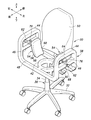
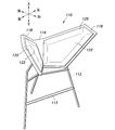
- Embodiment 1 of the chair according to the present invention will be described with reference to FIGS. 1 and 2.
- the chair 10 is of a stand chair specification, and is made of metal by a disc-shaped base 12 placed on the floor and a single pole 14 erected vertically from the center of the base 12.
- a leg (leg) 16 is provided.
- An upper support portion 18 made of a metal pipe is fixed to the upper portion of the leg portion 16.
- the upper support portion 18 extends substantially on the left and right sides of the pole 14 and has a substantially U shape when viewed from the front.
- the left and right pad members 20 are fixed to the left and right ends of the upper support 18 respectively.
- Each of the left and right pad members 20 includes a rectangular substrate 22 made of metal or synthetic resin, and a cushion portion 24 attached over the entire surface of one surface of the substrate 22, and extends along the side surface of the human buttocks. Thus, it has a shape curved in an inwardly concave arc shape in plan view.
- the left and right cushion portions 24 are each made of a repulsive material such as foamed urethane resin and have a sheet shape with a uniform thickness.
- the left and right pad members 20 are fixed to the end portion of the upper support portion 18 with the cushion portions 24 facing each other and arranged in a vertically inverted shape when viewed from the front.
- the surface on the side where the cushion portions 24 face each other is the pad surface 26.
- the left and right pad surfaces 26 are opposed to each other by being inclined in a direction approaching each other from the upper side to the lower side. Thereby, the separation distance in the left-right direction of the left and right pad surfaces 26 is gradually shortened from the upper side to the lower side.
- the inclination angle of the pad surface 26 with respect to the horizontal plane may be about 60 degrees.
- the left and right pad surfaces 26 are spaced apart from each other in the left-right direction by a distance greater than the left and right widths of a standard adult buttock (pelvis) on the upper end side, and smaller than the left and right widths of a standard adult buttock A (pelvis B) .
- the left and right pad surfaces 26 are at least partially on the left and right sides of the hipbone C of the pelvis B of a person sitting with the buttocks between the left and right pad surfaces 26 from the upper side to the lower side. Part, especially the part corresponding to the left and right sides of the iliac bone (upper anterior iliac spine D to lower anterior iliac spine E).
- the lower end and the lower part of the left and right pad members 20 are open, and there is no seat plate or a member corresponding to it to support the seat bone F from below. Thereby, the scapula F of the person sitting on the chair 10 is not supported from below.
- the left and right pad surfaces 26 correspond to the left and right sides of the hipbone C, respectively. Abut against the part. Thereby, the pad member 20 supports the upper limb load of an adult in a sitting posture without supporting the isch bone F from below by sandwiching a portion corresponding to the hipbone C from the left and right. At this time, the cushion part 24 is elastically deformed following the shape of the side part of the collar part, and holds the side part of the collar part stably.
- the upper limb load does not act on the pelvis B as a force in a direction to expand the pelvis B to the left and right, and when sitting, the pelvis B is sandwiched from the left and right sides by the left and right pad surfaces 26.
- the action is naturally obtained, and the pelvis B is tightened inward in the left and right directions by the horizontal component of the upper limb load acting on the left and right pad surfaces 26.
- the chair 10 has the lower side of the left and right pad members 20 open, and there is no seat plate that supports the seat bone F from below. People with such diseases can easily take a sitting posture without feeling pain. This also allows the pregnant woman to sit comfortably.
- the pelvis B is naturally sandwiched between the left and right pad surfaces 26 just by sitting on the chair 10, and the pelvis B is sandwiched by the left and right pad surfaces 26 simply by standing up from the chair 10. Therefore, the ease of sitting and standing is not hindered and the usability as a chair is not deteriorated.
- the seating referred to in the description of the embodiment is not to place the seat bone F on the seat plate or a member corresponding thereto, but to take a posture of sitting on a chair.
- the left and right pad members 20 are open in front in plan view as shown by phantom lines in FIG.
- it can be arranged in a C shape in which the distance between the left and right pad surfaces 26 in the left-right direction increases as it goes forward.
- the left and right pad surfaces 26 may be inclined so as to move away from each other as they go from the rear side to the front side.
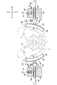
- the chair 30 according to the second embodiment is an office chair specification, and includes a leg 32 having a five-leg caster base 32 placed on the floor and a pole 34 erected vertically from the center of the base 32. It has a part (leg) 36. An upper support portion 38 is fixed to the upper portion of the leg portion 36. Since the pole 34 includes a gas-filled damper (not shown), the height of the upper support 38 on the floor can be adjusted by the adjustment lever 40 of the gas-filled damper.
- the upper support portion 38 includes a round collar 42 fixed to the upper end of the pole 34, left and right elbow rests 44 attached to the round collar 42, and a horizontal front and back below the elbow rest 44. And a frame-like portion 48 having left and right side beams 46 extending in the horizontal direction. A backrest member 50 is attached to the back side of the frame-like portion 48.
- Left and right pad members 54 are attached to the left and right side beams 46 by pad support mechanisms 52, respectively.
- Each of the left and right pad members 54 includes a rectangular substrate 56 made of metal or synthetic resin, and a cushion portion 58 attached over the entire surface of one surface of the substrate 56, and extends along the side surface of the human buttocks. Thus, it has a shape curved in an inwardly concave arc shape in both a plan view and a front view.
- the left and right cushion portions 58 are each made of a repulsive material such as foamed urethane resin to form a sheet having a uniform thickness, and the surfaces facing each other are the pad surfaces 60.
- the pad support mechanism 52 includes left and right horizontal rods 62 attached to the side beams 46 so as to be displaceable in the left-right direction, and spherical joints 64 attached to the inner ends of the left and right horizontal rods 62.
- the substrate 56 of the pad member 54 on the side corresponding to the spherical joint 64 is attached.
- the spherical joint 64 is a coupling mechanism with a lock that can be fixed in any changeable inclination posture, and a spherical surface with a lock that fixes the pad member 54 to the end of the horizontal rod 62 in any inclination posture by a lock screw 66. It is a joint. Thereby, the pad member 54 is fixed to the end portion of the horizontal rod 62 so that the inclination angle in the vertical direction and the inclination angle in the front-rear direction, in other words, the inclination angle in all directions can be changed.
- the horizontal rod 62 is formed with a series of ratchet teeth 68 in the axial direction (left-right direction).
- a ratchet claw 70 that is detachably engaged with one ratchet tooth 68
- a stem 72 having a ratchet claw 70 attached to one end thereof, and the ratchet claw 70 in the meshing direction with the ratchet tooth 68.
- a compression coil spring 74 to be urged and a ratchet release knob 76 attached to the other end of the stem 72 are provided for the operation of releasing the ratchet pawl 70 from engagement with the ratchet teeth 68.
- a rod operation knob 78 for manually moving the horizontal rod 62 in the axial direction is attached to the outer end portion of the horizontal rod 62.
- the ratchet mechanism including the ratchet teeth 68 and the ratchet pawl 70 prevents the horizontal rod 62 from moving outward in the axial direction (moving in the direction in which the left and right pad surfaces 60 are separated from each other in the left-right direction). Is a one-way locking mechanism that freely allows movement inward in the axial direction. Therefore, when the user grips the rod operation knob 78 and moves the horizontal rod 62 inward in the axial direction by manual operation, or in a state where the ratchet is released by the ratchet release knob 76, the horizontal rod 62 is moved out of the axial direction.
- the pad member 54 can be positioned at an arbitrary position in the left-right direction by moving in the direction. In this way, the position adjustment mechanism is configured, and the left and right separation distances of the left and right pad surfaces 60 can be variably set.
- the lower portions of the left and right pad members 54 are open, and there is no seat plate or a corresponding member for supporting the seat bone F from below.
- the left and right pad surface 60 has a lateral separation distance larger than the lateral width of the buttocks (pelvis B) on the upper end side and the hips A (pelvis B) on the lower end side.
- the left and right pad surfaces 60 are adjusted by adjusting the distance between the left and right pad surfaces 60 in the left-right direction and the vertical and forward tilt angles of the pad member 54 so as to be smaller than the left and right widths.
- the adjusted vertical inclinations of the left and right pad surfaces 60 are inclinations that approach each other as they go from the upper side to the lower side, and the inclinations in the front-rear direction are inclinations that move away from each other as they go from the rear side to the front side.
- the left and right pad surfaces 60 are set in a C-shaped arrangement that is upside down when viewed from the front, and a C-shaped arrangement with the front side opened in a plan view.
- the left and right pad surfaces 60 respectively correspond to the left and right side portions of the hipbone C. Abut.
- the pad member 54 supports the upper limb load of an adult in a sitting posture without supporting the seat bone F from below by sandwiching portions corresponding to the left and right sides of the hipbone C from the left and right.
- the cushion part 58 is elastically deformed following the shape of the side part of the collar part, and holds the side part of the collar part stably.
- the upper limb load does not act on the pelvis B as a force in the direction of expanding the pelvis B to the left and right, and if it sits, the pelvis B is sandwiched from the left and right sides by the left and right pad surfaces 60.
- the action is naturally obtained, and the pelvis B is tightened to the left and right inner sides by the horizontal component of the upper limb load acting on the left and right pad surfaces 60.
- This action effectively corrects the distortion of the pelvis B as opposed to inducing the left / right imbalance of the pelvis B just by sitting on the chair 30, and at the same time, lower back pain and sciatica
- the effect of preventing and reducing can be obtained.
- the lower portions of the left and right pad members 54 are open, and there is no seat plate that supports the seat bone F from below, so that there is no pressure on the patient who has undergone acupuncture surgery or the affected area of the hemorrhoid. People with these diseases can easily take a sitting posture without feeling pain. This also allows the pregnant woman to sit comfortably.
- the pelvis B is naturally sandwiched between the left and right pad surfaces 60 from both the left and right sides, and the pelvis B is sandwiched between the left and right pad surfaces 60 just by standing up.
- the ease of standing is not hindered and the usability as a chair is not deteriorated.
- the distance between the left and right pad surfaces 60 can be increased or decreased, and the pad member 54 can take any posture, so that it can be widely used for people of various physiques.
- left and right pad surfaces 60 are arranged in a C shape with the front side opened in plan view, and are inclined in a direction away from each other toward the front side from the rear side.
- the hip joint of the pelvis B does not become cramped, and the feeling of pressure at the time of sitting is reduced.
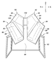
- the chair 80 of the third embodiment is of a reception chair specification, and left and right pad members 84 are fixed to the upper part of a frame-like leg (leg) 82 placed on the floor.
- the left and right pad members 84 each have a substrate 86 made of a metal or a synthetic resin and made of a rectangular flat plate that is long in the front-rear direction, and a cushion portion 88 that is attached to the entire surface of one surface of the substrate 86.
- Each of the left and right cushion portions 88 is made of a repulsive material such as urethane foam resin and has a uniform thickness except for the edges.
- Each of the left and right pad members 84 has a C-shaped arrangement that is vertically inverted in front view and a C-shaped arrangement in which the front side is opened in plan view, with the cushion portions 88 facing each other. It is fixed.
- the surface on the side where the cushion portion 88 faces each other is the pad surface 90
- the left and right pad surfaces 90 are inclined so as to approach each other from the upper side to the lower side, and from the front side to the rear side. As they go to the side, they incline in directions away from each other. That is, the left and right pad surfaces 90 are gradually shortened from the upper side toward the lower side and gradually decreased from the front side toward the rear side.
- the lower portions of the left and right pad members 84 are open, and there is no seat plate or a member corresponding to the seat plate that supports the seat bone F from below.
- the left and right pad surfaces 90 are separated from each other in the left-right direction by a distance larger than the left and right widths of a standard adult buttocks (pelvis) on the upper end side, and the standard adult buttocks A (pelvis B) on the lower end side. Smaller than With this setting, the left and right pad surfaces 90 are at least partially in the vertical direction on the left and right sides of the hipbone C of the pelvis B of a person sitting with a buttocks between the left and right pad surfaces 90 from above to below. Part, especially the part corresponding to the left and right sides of the iliac bone (upper anterior iliac spine D to lower anterior iliac spine E).
- the left and right backrest halves 92 are attached to the legs 82.
- the backrest halves 92 are a pair of left and right, and form a single backrest in cooperation with each other.
- Each of the backrest halves 92 covers a substrate 94 made of a metal or synthetic resin rectangular flat plate and one surface portion of the substrate 94.
- a cushion portion 96 attached thereto.
- the left and right cushion portions 96 are each made of a repulsive material such as urethane foam resin, and have a uniform thickness except for the edges.
- the lower end of the backrest half 92 is inclined upward and extends so as to be bent upward from the rear end of the pad member 84 on the corresponding side.
- the left and right back half halves 92 are arranged in the shape of a letter C that is inclined away from each other toward the outside in the left and right direction and opened frontward in plan view. This is a slit-like opening 100 that is continuous with an opening 98 between the lower ends of the pad member 84 (a C-shaped open portion whose front side is open).
- the upper ends of the left and right backrest halves 92 are connected to each other by a strip-like connecting member 102.
- the substrate 94 of the backrest half 92 and the substrate 86 of the pad member 84 may be integrated.
- the left and right pad surfaces 90 are respectively left and right of the hipbone C (see FIG. 1). It abuts on the part corresponding to the part.
- the pad member 54 supports the upper limb load of an adult in a sitting posture without supporting the seat bone F (see FIG. 1) from below by sandwiching portions corresponding to the left and right sides of the hipbone C from the left and right.
- the cushion part 88 is elastically deformed following the shape of the side part of the collar part, and holds the side part of the collar part stably.
- the upper limb load does not act on the pelvis B as a force in the direction of expanding the pelvis B (see FIG. 1) to the left and right. Is naturally obtained from both the left and right sides, and the pelvis B is tightened to the left and right inward by the horizontal component of the upper limb load acting on the left and right pad surfaces 90.
- a person sitting on the chair 80 can effectively correct the distortion of the pelvis B as opposed to inducing the left / right imbalance of the pelvis B. The effect of preventing and reducing can be obtained.
- the lower part of the left and right pad members 84 is opened by the opening 98, and there is no seat plate for supporting the sciaticus from below.
- people with these diseases can easily take a sitting posture without feeling pain. This also allows the pregnant woman to sit comfortably.
- the pelvis B is naturally sandwiched by the left and right pad surfaces 90 from both the left and right sides, and it is released that the pelvis is sandwiched by the left and right pad surfaces 90 just by standing up.
- the ease of use is not hindered and the usability as a chair does not deteriorate.
- the left and right pad surfaces 90 are arranged in a C shape with the front side opened in plan view, and are inclined in a direction away from each other toward the front side from the rear side.
- the hip joint part of the pelvis B sandwiched between the surfaces 90 is not cramped, and the feeling of pressure at the time of sitting is reduced.
- the left and right pad surfaces 60 are inclined away from each other toward the front side from the rear side and the length of the pad surface 90 in the front-rear direction is long as in the embodiment shown in FIGS. Can adjust the degree to which the left and right pad surfaces 60 pinch the pelvis B from both the left and right sides depending on the position of the person sitting on the chair 80 in the front-rear direction, that is, sitting deeply or shallowly. If it is desired to increase the degree to which the left and right pad surfaces 60 pinch the pelvis B from both the left and right sides, it may be sitting deep, and if it is desired to be weak, it should be sitting shallow.
- the left and right backrest halves 92 lean against the backrest halves 92 because they are inclined in a direction away from each other from the inner side to the outer side in the left and right direction and open in the front view in plan view.
- the person's back can be held stably without giving a feeling of pressure to the spine. This improves sitting comfort.
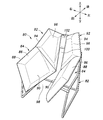
- the chair 110 is of a stand chair specification and includes a tripod-like leg (leg) 112 placed on the floor.
- a footrest bar 113 is attached to the front portion of the leg body 112.
- a substrate 116 of the pad member 114 is fixed to the upper portion of the leg (leg) 112.
- the substrate 116 is made of metal or synthetic resin, has a vertically inverted C shape when viewed from the front, and is bent into a C shape whose front side is open when viewed from above, with a pentagonal pad attached. It has the plane part 118 symmetrically.
- a pentagonal cushion member 120 is mounted on each of the left and right pad mounting flat portions 118.
- the surface on the side where the cushion members 120 face each other is a pad surface 122, and the left and right pad surfaces 122 each have two directions: a direction approaching from the upper side to the lower side and a direction away from each other from the rear side to the front side. Inclined in the direction and facing each other. That is, the left and right pad surfaces 122 are gradually separated from the upper side toward the lower side, and gradually separated from the rear side toward the front side. In other words, the left and right pad surfaces 122 are arranged in a C shape that is upside down when viewed from the front, and in a C shape that is open at the front side in plan view.
- the chair 110 can obtain the same operations and effects as those of the chair 80 of the third embodiment except for the backrest.
- the chair 110 can be stably seated by placing the foot on the footrest bar 113.
- connection mechanism for fixing the pad member 54 in any changeable inclination posture is not limited to the spherical joint 64, and the pad member 54 can be rotated when the inclination posture may be adjusted in one direction. It may be a shaft member that is supported on the shaft member and a lock screw that fixes the pad member 54 to the shaft member at an arbitrary rotational position.
Landscapes
- Health & Medical Sciences (AREA)
- Vascular Medicine (AREA)
- Animal Behavior & Ethology (AREA)
- Engineering & Computer Science (AREA)
- Biomedical Technology (AREA)
- Heart & Thoracic Surgery (AREA)
- Nursing (AREA)
- Life Sciences & Earth Sciences (AREA)
- Orthopedic Medicine & Surgery (AREA)
- General Health & Medical Sciences (AREA)
- Public Health (AREA)
- Veterinary Medicine (AREA)
- Orthopedics, Nursing, And Contraception (AREA)
- Mattresses And Other Support Structures For Chairs And Beds (AREA)
- Accommodation For Nursing Or Treatment Tables (AREA)
Abstract
Description
12 基部
14 ポール
16 脚部
18 上部支持部
20 パッド部材
22 基板
24 クッション部
26 パッド面
30 椅子
32 基部
34 ポール
36 脚部
38 上部支持部
40 調節レバー
42 丸形籠状部
44 肘載せ部
46 側部梁
48 枠状部
50 背もたれ部材
52 パッド支持機構
54 パッド部材
56 基板
58 クッション部
60 パッド面
62 水平ロッド
64 球面継手
68 ラチェット歯
70 ラチェット爪
72 ステム
74 圧縮コイルばね
76 ラチェット解除摘み
78 ロッド操作摘み
80 椅子
82 脚体
84 パッド部材
86 基板
88 クッション部
90 パッド面
92 背もたれ半体
94 基板
96 クッション部
98 開口
100 開口
102 連結部材
108 クッション部材
110 椅子
112 脚体
114 パッド部材
116 基板
118 パッド装着平面部
120 クッション部材
122 パッド面
A 臀部
B 骨盤
C 寛骨
F 座骨
Claims (6)
- 脚部と、
前記脚部の上部に取り付けられたパッド部材とを有し、
前記パッド部材は、上側から下側に向かうほど互いに近付く方向に傾斜して相対向し且つ座った姿勢の人の骨盤の左右側部に対応する部分に当接する左右のパッド面を含み、
座った人の座骨を下方から支持することなく座った人の上肢荷重を前記パッド部材によって支持するように構成されている椅子。 - 前記左右のパッド部材の下方が開放されている請求項1に記載の椅子。
- 前記左右のパッド面は、後側から前側に向かうほど互いに離れる方向に傾斜している請求項1または2に記載の椅子。
- 前記パッド部材は、左右個別のパッド部材によって構成され、左右のパッド面の離間距離を増減する方向に配置位置を変更可能な位置調整機構によって前記脚部に取り付けられている請求項1から3の何れか一項に記載の椅子。
- 前記パッド部材は、任意の傾斜姿勢で固定可能な連結機構によって前記脚部に取り付けられている請求項1から4の何れか一項に記載の椅子。
- 前記左右のパッド部材の後端部より上方に立ち上がり、左右方向の内側から外側に向かうほど互いに離れる方向に傾斜し、互いに協働して一つの背もたれをなす左右の背もたれ半体を有する請求項1から5の何れか一項に記載の椅子。
Priority Applications (5)
| Application Number | Priority Date | Filing Date | Title |
|---|---|---|---|
| KR1020167019314A KR20160130744A (ko) | 2013-12-17 | 2014-12-15 | 의자 |
| EP14871622.8A EP3085342A4 (en) | 2013-12-17 | 2014-12-15 | Chair |
| JP2015553374A JP6028108B2 (ja) | 2013-12-17 | 2014-12-15 | 椅子 |
| US15/104,899 US20160296024A1 (en) | 2013-12-17 | 2014-12-15 | Chair |
| CN201480068603.3A CN105828751A (zh) | 2013-12-17 | 2014-12-15 | 椅子 |
Applications Claiming Priority (2)
| Application Number | Priority Date | Filing Date | Title |
|---|---|---|---|
| JP2013260207 | 2013-12-17 | ||
| JP2013-260207 | 2013-12-17 |
Publications (1)
| Publication Number | Publication Date |
|---|---|
| WO2015093033A1 true WO2015093033A1 (ja) | 2015-06-25 |
Family
ID=53402403
Family Applications (1)
| Application Number | Title | Priority Date | Filing Date |
|---|---|---|---|
| PCT/JP2014/006231 Ceased WO2015093033A1 (ja) | 2013-12-17 | 2014-12-15 | 椅子 |
Country Status (7)
| Country | Link |
|---|---|
| US (1) | US20160296024A1 (ja) |
| EP (1) | EP3085342A4 (ja) |
| JP (1) | JP6028108B2 (ja) |
| KR (1) | KR20160130744A (ja) |
| CN (1) | CN105828751A (ja) |
| TW (1) | TW201531267A (ja) |
| WO (1) | WO2015093033A1 (ja) |
Cited By (1)
| Publication number | Priority date | Publication date | Assignee | Title |
|---|---|---|---|---|
| CN105853039A (zh) * | 2016-04-12 | 2016-08-17 | 杨晓波 | 一种妇产科用骨盆矫正器 |
Families Citing this family (8)
| Publication number | Priority date | Publication date | Assignee | Title |
|---|---|---|---|---|
| IT201600083098A1 (it) * | 2016-08-05 | 2018-02-05 | Leonardo Osti | Dispositivo posturale dinamico |
| CN108553261B (zh) * | 2018-05-15 | 2023-11-10 | 常州市第二人民医院 | 一种分娩球 |
| KR102173497B1 (ko) * | 2018-07-25 | 2020-11-03 | 주식회사 불스원 | 골반 시트 |
| CN110772065A (zh) * | 2019-11-27 | 2020-02-11 | 董叶锋 | 一种基于全身肌肉激活的身体平衡训练椅 |
| CN112841965B (zh) * | 2021-02-03 | 2022-09-02 | 深圳腾盛云科技有限公司 | 一种智能调节教学椅 |
| EP4282386A4 (en) * | 2021-03-01 | 2025-01-01 | Hideo Nakata | DEVICE FOR THE TREATMENT OF BACK PAIN |
| US11744375B2 (en) | 2021-07-14 | 2023-09-05 | Anthro Form, Llc | Seat configuration |
| CN115517497A (zh) * | 2022-09-09 | 2022-12-27 | 厦门南洋职业学院 | 一种辅助钢琴教学的多功能校正装置 |
Citations (6)
| Publication number | Priority date | Publication date | Assignee | Title |
|---|---|---|---|---|
| JP2002360376A (ja) | 2001-06-06 | 2002-12-17 | Keitaro Igawa | 骨盤サポート椅子 |
| WO2003034870A1 (en) | 2001-10-24 | 2003-05-01 | Sun Whan Kim | Chair having separate seat |
| JP2005516709A (ja) * | 2002-02-14 | 2005-06-09 | アレクセイ アレクシーヴィッチ バイコフ | 腰掛装置 |
| WO2006073019A1 (ja) * | 2005-01-07 | 2006-07-13 | Train Corporation | 椅子 |
| JP2006527062A (ja) * | 2003-06-12 | 2006-11-30 | キム、スン・ワン | 間隔調節が可能なシート装置 |
| JP2008073276A (ja) * | 2006-09-22 | 2008-04-03 | Kaito Tei | 骨盤クッション |
Family Cites Families (3)
| Publication number | Priority date | Publication date | Assignee | Title |
|---|---|---|---|---|
| CN200980473Y (zh) * | 2006-10-19 | 2007-11-28 | 大康控股集团有限公司 | 一种带有柔性靠背的椅子 |
| GB201110748D0 (en) * | 2011-06-24 | 2011-08-10 | Freedman Simon A | A seat |
| US8602493B1 (en) * | 2012-07-02 | 2013-12-10 | Yung-Kun Chen | Chair with a hip-shaping seat |
-
2014
- 2014-12-15 EP EP14871622.8A patent/EP3085342A4/en not_active Withdrawn
- 2014-12-15 WO PCT/JP2014/006231 patent/WO2015093033A1/ja not_active Ceased
- 2014-12-15 US US15/104,899 patent/US20160296024A1/en not_active Abandoned
- 2014-12-15 KR KR1020167019314A patent/KR20160130744A/ko not_active Withdrawn
- 2014-12-15 JP JP2015553374A patent/JP6028108B2/ja active Active
- 2014-12-15 CN CN201480068603.3A patent/CN105828751A/zh active Pending
- 2014-12-16 TW TW103143839A patent/TW201531267A/zh unknown
Patent Citations (7)
| Publication number | Priority date | Publication date | Assignee | Title |
|---|---|---|---|---|
| JP2002360376A (ja) | 2001-06-06 | 2002-12-17 | Keitaro Igawa | 骨盤サポート椅子 |
| WO2003034870A1 (en) | 2001-10-24 | 2003-05-01 | Sun Whan Kim | Chair having separate seat |
| JP2005516709A (ja) * | 2002-02-14 | 2005-06-09 | アレクセイ アレクシーヴィッチ バイコフ | 腰掛装置 |
| JP2006527062A (ja) * | 2003-06-12 | 2006-11-30 | キム、スン・ワン | 間隔調節が可能なシート装置 |
| JP4546957B2 (ja) | 2003-06-12 | 2010-09-22 | キム、スン・ワン | 間隔調節が可能なシート装置 |
| WO2006073019A1 (ja) * | 2005-01-07 | 2006-07-13 | Train Corporation | 椅子 |
| JP2008073276A (ja) * | 2006-09-22 | 2008-04-03 | Kaito Tei | 骨盤クッション |
Non-Patent Citations (1)
| Title |
|---|
| See also references of EP3085342A4 |
Cited By (1)
| Publication number | Priority date | Publication date | Assignee | Title |
|---|---|---|---|---|
| CN105853039A (zh) * | 2016-04-12 | 2016-08-17 | 杨晓波 | 一种妇产科用骨盆矫正器 |
Also Published As
| Publication number | Publication date |
|---|---|
| EP3085342A4 (en) | 2017-08-23 |
| CN105828751A (zh) | 2016-08-03 |
| JPWO2015093033A1 (ja) | 2017-03-16 |
| KR20160130744A (ko) | 2016-11-14 |
| EP3085342A1 (en) | 2016-10-26 |
| US20160296024A1 (en) | 2016-10-13 |
| TW201531267A (zh) | 2015-08-16 |
| JP6028108B2 (ja) | 2016-11-16 |
Similar Documents
| Publication | Publication Date | Title |
|---|---|---|
| JP6028108B2 (ja) | 椅子 | |
| EP2559358B1 (en) | Lumbar support seat | |
| KR20140046443A (ko) | 좌석 | |
| KR20140077888A (ko) | 사용자의 두개골을 지지하기 위한 방법, 몸 지지 구조체, 및 2레벨 머리받침대 | |
| US20010040402A1 (en) | Adjustable split seat | |
| KR101091283B1 (ko) | 자세교정용 의자 | |
| KR20190014681A (ko) | 자세교정의자 | |
| KR101502128B1 (ko) | 요가 의자 | |
| CN216854219U (zh) | 一种腰椎健康仿生束腰靠垫及座椅 | |
| EP1272071B1 (en) | A chair | |
| KR101815183B1 (ko) | 디스크 방지용 방석 | |
| JP6112768B2 (ja) | 着座器具 | |
| JP3249163U (ja) | 椅子 | |
| JP2006334025A (ja) | 着座用家具 | |
| JP2010004967A (ja) | 骨盤クッション | |
| JP3249162U (ja) | 椅子 | |
| JP2018149039A (ja) | 矯正補助具 | |
| CN216854230U (zh) | 一种腰椎健康仿生折叠式靠垫 | |
| CN216854218U (zh) | 一种腰椎健康仿生气囊靠垫及座椅 | |
| KR102487012B1 (ko) | 다리의 벌어짐을 고정하는 자세교정용 보조 의자 | |
| CN202160983U (zh) | 具有稳定就座装置的座椅 | |
| RU2737814C1 (ru) | Ортопедическое сиденье | |
| JP3100529U (ja) | 自然体療法脊椎矯正椅子 | |
| KR20250145308A (ko) | 요추받이용 좌판 및 이를 구비하는 의자 | |
| JP2008073276A (ja) | 骨盤クッション |
Legal Events
| Date | Code | Title | Description |
|---|---|---|---|
| 121 | Ep: the epo has been informed by wipo that ep was designated in this application |
Ref document number: 14871622 Country of ref document: EP Kind code of ref document: A1 |
|
| ENP | Entry into the national phase |
Ref document number: 2015553374 Country of ref document: JP Kind code of ref document: A |
|
| WWE | Wipo information: entry into national phase |
Ref document number: 15104899 Country of ref document: US |
|
| NENP | Non-entry into the national phase |
Ref country code: DE |
|
| REEP | Request for entry into the european phase |
Ref document number: 2014871622 Country of ref document: EP |
|
| WWE | Wipo information: entry into national phase |
Ref document number: 2014871622 Country of ref document: EP |
|
| ENP | Entry into the national phase |
Ref document number: 20167019314 Country of ref document: KR Kind code of ref document: A |