WO2015093073A1 - シミュレーション装置 - Google Patents
シミュレーション装置 Download PDFInfo
- Publication number
- WO2015093073A1 WO2015093073A1 PCT/JP2014/061689 JP2014061689W WO2015093073A1 WO 2015093073 A1 WO2015093073 A1 WO 2015093073A1 JP 2014061689 W JP2014061689 W JP 2014061689W WO 2015093073 A1 WO2015093073 A1 WO 2015093073A1
- Authority
- WO
- WIPO (PCT)
- Prior art keywords
- node
- position information
- binary tree
- unit
- complete binary
- Prior art date
- Legal status (The legal status is an assumption and is not a legal conclusion. Google has not performed a legal analysis and makes no representation as to the accuracy of the status listed.)
- Ceased
Links
Images






Classifications
-
- G—PHYSICS
- G06—COMPUTING OR CALCULATING; COUNTING
- G06F—ELECTRIC DIGITAL DATA PROCESSING
- G06F30/00—Computer-aided design [CAD]
- G06F30/20—Design optimisation, verification or simulation
-
- A—HUMAN NECESSITIES
- A63—SPORTS; GAMES; AMUSEMENTS
- A63F—CARD, BOARD, OR ROULETTE GAMES; INDOOR GAMES USING SMALL MOVING PLAYING BODIES; VIDEO GAMES; GAMES NOT OTHERWISE PROVIDED FOR
- A63F13/00—Video games, i.e. games using an electronically generated display having two or more dimensions
- A63F13/40—Processing input control signals of video game devices, e.g. signals generated by the player or derived from the environment
- A63F13/44—Processing input control signals of video game devices, e.g. signals generated by the player or derived from the environment involving timing of operations, e.g. performing an action within a time slot
-
- A—HUMAN NECESSITIES
- A63—SPORTS; GAMES; AMUSEMENTS
- A63F—CARD, BOARD, OR ROULETTE GAMES; INDOOR GAMES USING SMALL MOVING PLAYING BODIES; VIDEO GAMES; GAMES NOT OTHERWISE PROVIDED FOR
- A63F13/00—Video games, i.e. games using an electronically generated display having two or more dimensions
- A63F13/55—Controlling game characters or game objects based on the game progress
- A63F13/57—Simulating properties, behaviour or motion of objects in the game world, e.g. computing tyre load in a car race game
- A63F13/577—Simulating properties, behaviour or motion of objects in the game world, e.g. computing tyre load in a car race game using determination of contact between game characters or objects, e.g. to avoid collision between virtual racing cars
-
- G—PHYSICS
- G06—COMPUTING OR CALCULATING; COUNTING
- G06T—IMAGE DATA PROCESSING OR GENERATION, IN GENERAL
- G06T17/00—Three-dimensional [3D] modelling for computer graphics
- G06T17/005—Tree description, e.g. octree, quadtree
-
- G—PHYSICS
- G06—COMPUTING OR CALCULATING; COUNTING
- G06T—IMAGE DATA PROCESSING OR GENERATION, IN GENERAL
- G06T2210/00—Indexing scheme for image generation or computer graphics
- G06T2210/21—Collision detection, intersection
-
- G—PHYSICS
- G06—COMPUTING OR CALCULATING; COUNTING
- G06T—IMAGE DATA PROCESSING OR GENERATION, IN GENERAL
- G06T2210/00—Indexing scheme for image generation or computer graphics
- G06T2210/52—Parallel processing
Definitions
- the present invention relates to a simulation apparatus that executes a simulation on a plurality of objects that move in a virtual space with time, a control method therefor, a program, and an information storage medium.
- collision determination is performed based on the positions of the two objects in the virtual space.
- it is inefficient to perform collision determination with a brute force for a plurality of objects because the amount of calculation increases as the number of objects increases. Therefore, conventionally, as one method for reducing the number of collision determinations, collision determination using a binary tree that reflects the positional relationship between a plurality of objects in a virtual space is performed. By using a binary tree reflecting the positional relationship between objects, it is possible to skip collision determination between objects whose positions in the virtual space are separated.
- an area including all objects is a root
- each divided area obtained by dividing the area into two is a child node
- each divided area is further divided into two grandchild nodes.
- the conventional binary tree construction method may not be able to perform parallel processing efficiently because the number of objects included in the divided areas of each layer is different.
- One of the objects of the present invention is to provide a method for constructing a binary tree that reflects the position of an object in a virtual space for performing object collision determination, which is suitable for parallel processing.
- the simulation apparatus is a simulation apparatus that determines a collision between objects at each of a plurality of calculation points for a plurality of objects that move in a virtual space with time, and at each of the plurality of calculation points,
- a complete binary tree creating unit for creating a complete binary tree in which position information indicating the position of the object in the virtual space at the time of the calculation is associated with a leaf, and position information reflecting the position information of the child node is associated with an internal node; , in each layer from one layer above the lowermost layer in the complete binary tree in this order, 2 n (n ⁇ 1) for each number of nodes, associated with a 2 ⁇ 2 n pieces of child nodes respectively belonging to the 2 n pieces of node was based on the positional information, and the node replacement section replacing the 2 ⁇ 2 n pieces of child nodes,
- the collision determination between objects is performed using the complete binary tree replaced by the node swapping unit has been performed.
- position information indicating a position of the object is an area that is inscribed the object corresponding the node interchanging unit, 2 ⁇ 2 n pieces of child nodes belonging to the 2 n pieces of node May be replaced with a combination in which the area of the parent node becomes smaller.
- the node replacement unit randomly sets the size of the region of the parent node in each combination candidate for each of a plurality of combination candidates obtained by replacing the 2 ⁇ 2 n child nodes. is changed to, as regions of varying the size becomes smaller combination candidate, it is also possible to replace the 2 ⁇ 2 n pieces of child nodes belonging to the 2 n pieces of node.
- the simulation apparatus described above determines whether or not there is an overlap in the area of each node for each two nodes in each layer in order from the top layer. It is good also as including further the judgment part which judges.
- the determination unit may include the combination of all four child nodes belonging to the two nodes determined to be overlapped by the determination unit in the previous layer in the region of each node. It may be further determined whether or not there is an overlap.
- the complete binary tree creation unit creates a complete binary tree used for collision determination at the previous calculation time when creating a complete binary tree used for collision determination at the second or later calculation time. It is also possible to create a complete binary tree using the correspondence between leaves and objects.
- the program according to the present invention provides a simulation apparatus that determines a collision between objects at each of a plurality of determination points for a plurality of objects that move in the virtual space with time.
- a complete binary tree creating means for creating a complete binary tree in which position information indicating the position of a node is associated with a leaf and the position information reflecting the position information of a child node is associated with an internal node; and from the lowest layer in the complete binary tree Based on the position information associated with each of 2 ⁇ 2 n child nodes belonging to the 2 n nodes, for each 2 n (n ⁇ 1) nodes in each layer in order from the upper layer, 2.2 Program for functioning as node replacement means for replacing n child nodes.
- This program may be stored in a computer-readable information storage medium.
- the control method of the simulation apparatus is a control method for controlling a simulation apparatus that determines a collision between objects at each of a plurality of determination points for a plurality of objects that move in a virtual space with time.
- 2 n (n ⁇ 1) for each number of nodes, associated with a 2 ⁇ 2 n pieces of child nodes respectively belonging to the 2 n pieces of node was based on the positional information, the nodes interchange stearyl replacing the 2 ⁇ 2 n pieces of child nodes Characterized in that it comprises a flop, a.
- FIG. 11A It is a figure which shows an example of the complete binary tree after the node replacement process about a 3rd layer is completed. It is a figure which shows an example of the acquisition object pair and the object check table which manages allocation of an acquisition object pair. An example of a judgment object pair and a comparison object pair is shown. It is a flowchart which shows an example of the flow of the physical quantity calculation process of the object using the common object pair which concerns on this embodiment. It is a figure which shows an example of the connection procedure of an object. It is a figure which shows typically an example of the connection object connected by the object connection part. It is a figure which shows typically an example of the connection object after updating the pointer value of each object about the connection object shown to FIG. 11A. It is a figure which shows typically an example of the connection object after updating the pointer value of each object about the connection object shown to FIG. 11B. It is a figure which shows transition of the pointer value of each object shown to FIG. 11A.
- FIG. 1 is a diagram illustrating an example of a configuration of a simulation apparatus 1 according to the present embodiment.
- the simulation apparatus 1 according to the present embodiment is, for example, a home game machine or a personal computer, and as illustrated in FIG. 1, a control unit 11, a storage unit 12, a communication unit 13, an operation unit 14, and a display unit. 15 is comprised.
- the control unit 11 includes a CPU 5, a GPU 6, and the like, and executes various types of information processing according to programs stored in the storage unit 12. In the present embodiment, a specific example of processing executed by the control unit 11 will be described later.
- the storage unit 12 includes a memory element such as a RAM or a ROM, a hard disk drive, and the like, and stores programs executed by the control unit 11 and various data.
- the storage unit 12 also operates as a work memory for the control unit 11.
- the communication unit 13 is a communication interface, receives data coming from the outside via a communication network, and outputs it to the control unit 11. Moreover, according to the instruction
- the operation unit 14 is a keyboard, a mouse, a controller of a consumer game machine, or the like, and receives a user operation input and outputs a signal indicating the content to the control unit 11.
- the display unit 15 is a display device such as a liquid crystal display, and displays various images in accordance with instructions from the control unit 11.
- the simulation apparatus 1 may include an optical disk drive, a USB (Universal Serial Bus) port, and the like for reading an optical disk such as a DVD-ROM and a Blu-ray (registered trademark) disk.
- an optical disk drive such as a DVD-ROM and a Blu-ray (registered trademark) disk.
- the simulation apparatus 1 for a plurality of objects that move in the virtual space, the positions of the objects that change with time are calculated by a simulation process such as a physical simulation.
- a simulation process is performed in consideration of the influence on the position of each object due to the collision between the objects.
- This simulation process is mainly executed by the GPU 6 of the control unit 11, but may be executed by the CPU 5 and other devices.
- the GPU 6 Since the GPU 6 has a larger number of cores than the CPU 5 and the number of processing units (threads) that can be executed simultaneously, it is suitable for parallel processing. On the other hand, threads that are executed simultaneously are required to have the same processing. Therefore, in order to efficiently execute the simulation process using the GPU 6, it is necessary to perform the process with an algorithm different from the conventional one.
- each object is associated with ID information (identifier) that is uniquely set to identify the object.
- ID information identifier
- attribute information may be associated with each object.
- the attribute information may be, for example, information indicating the type of object, information defining the outer shape, and other various attribute information according to the type of object.
- a physical quantity (speed, acceleration, etc.) is given to at least some of the plurality of objects arranged in the virtual space (S1).
- positioned in virtual space changes with time.
- constraint conditions for the two objects determined to collide with each other in the process S1 are created (S3).
- a constraint condition for constraining the movement of such an object is created.
- a physical quantity given to each object to satisfy the constraint condition is calculated (S4). The process S4 will be described in detail later.
- the physical quantity given to each object is reflected in the position in the virtual space (S6). That is, the position of each object at the timing of drawing the state of the virtual space is calculated from the physical quantity given to each object. Then, the simulation apparatus 1 draws an image indicating the state of the virtual space in which the object is arranged at the calculated position, and outputs the image to the display unit 15. As a result, each time the unit time d elapses, an image of the virtual space in which each object is arranged at the current position calculated by the simulation apparatus 1 is displayed on the screen of the display unit 15.
- the object collision determination process in the process S2 the object physical quantity calculation process in the process S4, and the object sleep management process in the process S5 will be described in detail below.
- FIG. 3 is a functional block diagram illustrating an example of main functions executed by the simulation apparatus 1 according to the present embodiment.
- the control unit 11 of the simulation apparatus 1 functionally includes, for example, a complete binary tree creation unit 21, a node replacement unit 22, a collision determination unit 23, and an object pair information acquisition unit. 31, a rearrangement unit 32, an identification unit 33, an allocation unit 34, a calculation unit 35, a value addition unit 41, a pointer value overwrite unit 43, a route value overwrite unit 43, and a pointer value update unit 45.
- These functions are realized by the control unit 11 executing a program stored in the storage unit 12.
- This program is supplied to the simulation apparatus 1 via a computer-readable information storage medium such as an optical disk, a magnetic disk, a magnetic tape, a magneto-optical disk, or a flash memory, or via communication means such as the Internet.
- the object collision determination process is realized by the complete binary tree creation unit 21, the node replacement unit 22, and the collision determination unit 23 illustrated in FIG.
- the complete binary tree creation unit 21 associates position information indicating the position of each of a plurality of objects arranged in the virtual space with the leaf, and associates position information reflecting the position information of the child node with the internal node. Create a complete binary tree.
- the position information indicating the position of the object in the virtual space is the position of each object in the virtual space based on the attribute information associated with the object (for example, information defining the outer shape) and the coordinate information of the virtual space. It may indicate a relationship.
- a so-called boundary volume (Boundary Volume) that includes an object is used as position information.
- This boundary volume is a simplified representation of the position and size of the area inscribed in the virtual space. Since the boundary volume is a simplified shape of the object, the collision determination for the boundary volume can be performed faster than the collision determination for the detailed model of the object.
- a sphere for example, a sphere (SPHERE), an axis parallel bounding box (Axis-Aligned Bounding Box; AABB), which is a rectangular parallelepiped having sides parallel to each axis (x, y, z axis), or the like is used.
- AABB axis parallel bounding box
- the bounding volume is an axis parallel bounding box
- the coordinate values of the minimum point where the coordinate value of each axis is the minimum and the maximum point where the coordinate value of each axis is the maximum among the vertices of the axis parallel bounding box is This is position information.
- the center coordinates of the axis parallel bounding box and the distances from the center to each of three planes orthogonal to each other may be used as position information. That is, the position information only needs to indicate the shape of the boundary volume of the object and the position in the virtual space.
- the complete binary tree creation unit 21 associates information (such as the coordinate value of the minimum point and the coordinate value of the maximum point) of each of the plurality of objects arranged in the virtual space with the leaf as position information. At this time, the complete binary tree creation unit 21 may associate the position information of each object with the leaf in the order of the identifiers associated with each object, or may associate the position information of each object with the leaf at random.
- the complete binary tree creating unit 21 creates a new inscribed in the boundary volume indicated by each of the two pieces of positional information associated with the two child nodes, with the parent node having two leaves as child nodes.
- the boundary volume information is associated as position information. Specifically, information on a new axis parallel bounding box including the axis parallel bounding box indicated by the two position information associated with the two leaves that are child nodes of the parent node is used as the position of the parent node. Associate as information.
- the complete binary tree creation unit 21 performs this process for every two leaves, and associates position information with each parent node.
- the complete binary tree creation unit 21 includes the axis parallel bounding box indicated by the two pieces of position information associated with the two nodes in the parent node having two nodes associated with the position information as child nodes.
- the information on the new axis parallel bounding box to be related is related as position information.
- the complete binary tree creation unit 21 performs this process for every two nodes, and associates position information with each parent node. In this way, the complete binary tree creation unit 21 creates a complete binary tree in which position information is associated with all nodes by executing the process of associating position information with the parent node for every two nodes up to the root. To do.
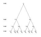
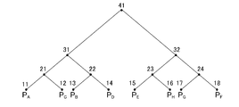
- the complete binary tree creating unit 21 includes the second layer, the third layer, and the fourth layer in order, with the leaf as the first layer, and the fourth layer as a root.
- the leaves of the first layer are the leaves 11 to 18 from the left
- the nodes of the second layer are the nodes 21 to 24 from the left
- the nodes of the third layer are the nodes 31 and 32 from the left.
- the complete binary tree creation unit 21 associates the position information P A to P H of each object with the leaves 11 to 18 in the first layer in the order of identifiers.
- the complete binary tree creation unit 21, containing a shaft parallel bounding volumes indicated by the positional information P A associated with a leaf 11, a shaft parallel bounding volumes indicated by the position information P B associated with a leaf 12, the the new axis parallel bounding volume to as P AB, associated with node 21.
- complete binary tree creation unit 21 a shaft parallel bounding volumes indicated by the positional information P C associated with a leaf 13, a shaft parallel bounding volume P D indicated by the positional information associated with the leaves 14, the new axis parallel bounding volume enclosing as P CD, associated with node 22.
- the complete binary tree creation unit 21 associates a new axis parallel boundary volume containing the axis parallel boundary volume indicated by the position information associated with the two child nodes with the parent node, the node 23 P EF , node 24 is associated with P GH , and node 32 is associated with P EFGH .
- the position information associated with the root is an axis parallel boundary volume that includes all of the objects A to H arranged in the virtual space.
- the node exchanging unit 22 converts 2 n (n ⁇ 1) nodes to 2 n nodes from one layer above the lowest layer (leaf layer) of the complete binary tree created by the complete binary tree creating unit 21. based on 2 ⁇ 2 n pieces of child node position information associated with each belonging, replacing the 2 ⁇ 2 n pieces of child nodes.
- the node replacing unit 22 replaces the position information of each object associated with the leaf of the complete binary tree created by the complete binary tree creating unit 21 into a form reflecting the positional relationship in the virtual space.
- the process executed by the node replacement unit 22 will be described in detail using the complete binary tree illustrated in FIG.
- the node replacement unit 22 has two nodes (node 21 and node 22, node 23 and node 24) in the second layer of the complete binary tree created by the complete binary tree creation unit 21.
- the child nodes are switched based on the four pieces of positional information (P A to P D , P E to P H ) associated with the child nodes (leaf 11 to leaf 14, leaf 15 to leaf 18).
- P A to P D , P E to P H the processing for the node 21 and the node 22
- the processing for the node 23 and the node 24 is also executed at the same time.
- the node replacement section 22 selects position information P B, P C, and P D is out of the axis parallel bounding box respectively, those relatively close relationship with the axis parallel bounding box indicating the position information P A To do.
- node replacement section 22 position information P A and the position information P B, position information P A and the position information P C, position information P A and the position information P D, the axis parallel bounding box indicating two position information for each of The volume of the new axis parallel bounding box that includes ## EQU1 ## is calculated as V AB , V AC , and V AD , respectively. And it is judged that the position of the axis parallel boundary box which two position information shows is so near that this volume is small.
- the node replacement unit 22 replaces the position information P A to P D so that the combination with the smallest volume belongs to the node 21. For example, if the volume V AC is determined to smallest, nodes interchanging unit 22, position information P A and the position information P C belongs to node 21, the position information P B and the position information P D belongs to the node 22 as replaces the position information P C and the position information P B.
- the position information P A and the position information P C is a new axis parallel bounding box enclosing the axis parallel bounding box respectively associated with node 21 as the position information P AC, position information P B and the position information P D, respectively new axis parallel bounding box enclosing the axis parallel bounding box that is associated with node 22 as the position information P BD.
- the node replacement unit 22 is a child of each of the two nodes (node 31 and node 32) in the third layer of the complete binary tree in which the nodes are replaced for the second layer.
- the same processing as the processing in the second layer described above is executed for the node.
- the complete binary tree illustrated in FIG. 4 is up to the fourth layer. However, in a complete binary tree having a deeper hierarchy, such processing is executed in each layer until the uppermost layer (root).
- the node replacement unit 22 obtains the sum of the volumes of the axis parallel bounding boxes indicated by the position information associated with the nodes 21 and 22 in each combination candidate (V AB + V CD , V AC + V BD , V respectively AD + V BC ). Then, the combination having the smallest value among V AB + V CD , V AC + V BD , and V AD + V BC is selected as the optimal combination. Then, the node replacement unit 22 replaces each node so that the selected optimum combination is obtained.
- the node replacement unit 22 determines a combination of two axis parallel boundary boxes that are relatively close to each other from the axis parallel boundary boxes associated with each of the plurality of child nodes to be replaced. In order to do this, the volume of the axis parallel bounding box that contains the two axis parallel bounding boxes that are the combination candidates is actually calculated, and the volume is associated with the two axis parallel bounding boxes that are included in the axis parallel bounding box whose volume is small. The child nodes are switched so that the two child nodes belong to the same parent node.
- the node replacement unit 22 is not limited to such a method, and may determine a combination of two axis parallel bounding boxes that are relatively close to each other by various methods.
- the node replacement unit 22 uses the numerical values such as the sum of the lengths of the three sides of the axis parallel bounding box including the two axis parallel bounding boxes as the combination candidates and the lengths of the diagonal lines as the determination criteria, and the positional relationship A combination of two axis parallel bounding boxes that are relatively close may be determined. Even in this case, it can be determined that the smaller the numerical value used as a criterion, the smaller the size of the axis parallel boundary box itself that contains the two axis parallel boundary boxes, and the positions of the two axis parallel boundary boxes are relatively close. I can judge.
- FIG. 5 shows a simplified model of a plurality of objects arranged in the virtual space.
- the simple model shown in FIG. 5 is an object in which objects of equal size (one grid indicates an object) are arranged in a grid-like two-dimensional space (xy coordinates).
- eight objects A to H identifiers A to H
- the axis parallel bounding box as the position information is also represented by a grid.
- the position information PA of the object A includes the coordinate value (0, 2) of the minimum point at which the coordinate value of each axis is minimum, and
- the axis parallel bounding box is represented by the coordinate value (1, 3) of the maximum point at which the coordinate value of each axis is maximum.
- An object is to create a complete binary tree reflecting the positional relationship between the objects A to H in the two-dimensional space.
- complete binary tree creation unit 21 associated with a leaf 11 to the leaf 18 the position information of the respective objects A ⁇ object H P A ⁇ P H to the identifier order to create a complete binary tree shown in FIG. 6A.
- the node replacement unit 22 has the position information P A and the position information P B , the position information P A and the position information P C , the position information P A and the position information P D for the node 21 and the node 22 in the second layer. For each, the volume of a new axis parallel bounding box that includes the axis parallel bounding box indicated by the two pieces of position information (corresponding to an area in the simple model) is obtained.
- the area V (xl ⁇ xs) (yl ⁇ ys).
- the axis parallel boundary indicated by the position information P A minimum point (0, 2), maximum point (1, 3)) and position information P B (minimum point (5, 4), maximum point (6, 5)).
- the new axis parallel bounding box P AB that contains the box is represented by a minimum point (0, 2) and a maximum point (6, 5).
- the axis indicated by the position information P A (minimum point (0, 2), maximum point (0, 3)) and position information P C (minimum point (2, 2), maximum point (3, 3)).
- the axis parallel bounding box indicated by the position information P A (minimum point (0, 2), maximum point (0, 3)) and position information P D (minimum point (2, 4), maximum point (3, 5))
- position belongs as position information P B in the information interchanged and P C.
- the position information P E and position information P F , the position information P E and position information P G , the position information P E and the position information P H are also included for each of the nodes 23 and 24 in the second layer.
- the node replacement unit 22 performs a node replacement process for the third layer using the complete binary tree of FIG. 6B.
- the position information P AC and the position information P BD the position information P AC and the position information P EH , the position information P AC and the position information P GF , the axes indicated by the two position information
- node replacement section 22 replaces the positional information P BD to position information P AC and the position information P EH belongs to the node 31 and the position information P EH, processing by the node replacement section 22 Exit. From the above, the complete binary tree after the node replacement process for the third layer is completed is shown in FIG. 6C. As a result, a complete binary tree reflecting the positional relationship of the objects in the virtual space shown in FIG. 6C is obtained.
- the complete binary tree creation unit 21 associates the position information P A , P C , P E , P H , P B , P D , P G , and P F from the left of the leaf.
- the node replacement process based on the positional information associated with the child nodes of 2 n nodes performed by the node replacement unit 22 can be executed with the same algorithm regardless of which 2 n nodes are selected. Become. Therefore, the node replacement unit 22 can execute the node replacement process for each of the 2 n nodes in each layer in parallel.
- the complete binary tree completed by the node replacement process by the node replacement unit 22 described above may not be an optimal complete binary tree reflecting the positional relationship of objects in the virtual space. This is because, when the node replacement unit 22 divides the object in the virtual space into combinations for each two objects, the local solution is obtained when performing an optimization process for obtaining a combination that minimizes the positional relationship between the two objects. Due to falling into. Therefore, processing for reducing the possibility of falling into a local solution executed by the node replacement unit 22 will be described. As described above, the node replacement unit 22 determines a combination of two pieces of positional information that are relatively close to each other from the positional information associated with each of the plurality of child nodes to be replaced.
- the node replacement unit 22 obtains a numerical value that quantitatively indicates the positional relationship between the two child nodes in the combination candidate, and either increases or decreases the numerical value. Change randomly (ie, add noise to the number). Then, a combination candidate having a smaller numerical value after the change is adopted, and node replacement processing is executed so as to become the combination candidate.
- the node replacement unit 22 is a numerical value that quantitatively indicates the positional relationship between two child nodes, and the size of an area that includes the area indicated by each of the two pieces of positional information associated with the two child nodes ( For example, the volume of the axis parallel bounding box is used.
- the node replacement unit 22 selects a combination that minimizes the sum of the volumes of the axis parallel bounding boxes indicated by the position information associated with each of the node 21 and the node 22 from each combination candidate.
- the node replacement unit 22 calculates the sum of the volumes of the axis parallel bounding boxes indicated by the position information associated with each of the nodes 21 and 22, the volume of the axis parallel bounding box indicated by the position information associated with each node.
- Noise is added to (V AB , V CD , V AC, V BD , V AD , V BC ).
- the sum of the volumes of the axis parallel bounding boxes indicated by the position information associated with each of the node 21 and the node 22 is (1 + ⁇ 1 ) V AB + (1 + ⁇ 2 ) V CD , (1 + ⁇ 3 ) V AC + (1 + ⁇ 4 ) V BD , (1 + ⁇ 5 ) V AD + (1 + ⁇ 6 ) V BC .
- ⁇ m is determined in advance as three types of values, and may be randomly assigned to each combination candidate.
- the node replacement unit 22 selects a combination that minimizes the sum of the volumes of the axis parallel bounding boxes indicated by the two pieces of position information to which these noises are added, from each combination candidate, and replaces the nodes.
- the node replacement unit 22 replaces its child node every two nodes, the possibility of falling into a local solution is reduced, and finally the positional relationship of objects in the virtual space is reflected. An optimal complete binary tree is completed.
- the node replacement unit 22 uses the size of the area inscribed in the two areas indicated by the two position information as a value that quantitatively indicates the positional relationship between the two child nodes in each combination candidate.
- the volume of the axis parallel bounding box that includes the axis parallel bounding box indicated by the two pieces of position information is used, but the present invention is not limited to this example.
- the node exchanging unit 22 quantitatively determines the positional relationship between the two pieces of position information by using a numerical value such as the sum of the lengths of the three sides of the axis parallel bounding box indicated by the two pieces of position information as combination candidates and the length of the diagonal line. It may be used as the value shown.
- the node replacement unit 22 randomly changes a numerical value used as a value that quantitatively indicates the positional relationship between the two child nodes, and executes a node replacement process based on the changed numerical value.
- the collision determination unit 23 executes a simulation process for performing a collision determination between objects using the complete binary tree that has been replaced by the node replacement unit 22.
- the collision determination is performed on the child nodes of each node of the complete binary tree based on the associated positional information.
- a collision determination method for example, based on position information using a boundary volume of a sphere, it is determined that the boundary volumes of the sphere collide when the distance of the center coordinate is smaller than the sum of two radii. There is a way.
- the axis parallel boxes collide with each other.
- the distance of the center coordinates in each axis is two radii (the distance from the center to the surface). )
- the axis parallel bounding boxes collide with each other when it is determined that the sum is smaller than all three axes.
- the collision determination by the collision determination unit 23 is performed using the complete binary tree in which the nodes are replaced by the node replacement unit 22.
- the collision determination unit 23 performs collision determination on the two nodes in each layer in order from the root to the leaf of the complete binary tree based on the positional information associated with each node.
- the collision determination unit 23 determines the four child nodes of the two nodes. Perform collision detection for all combinations.
- the collision determination unit 23 performs a collision determination between the child nodes of the two nodes.
- the process is executed based on the idea that the child nodes can be determined not to collide with each other. Since the position information associated with the node includes the position information of all lower nodes belonging to the node, if it is determined that there is no collision in the position information associated with the upper node, the position information associated with the lower node It can be said that there is no collision. Thereby, the collision determination unit 23 can skip the collision determination between objects that do not collide.
- the collision determination unit 23 performs the collision determination in each layer in order from the third layer to the first layer of the complete binary tree illustrated in FIG. 6C that has been replaced by the node replacement unit 22.
- the collision determination unit 23 the node between the third layer (node 31 and node 32), and position information P aceh associated with the node 31, and position information P BDGF associated with the node 32, the Based on the above-described collision determination method, collision determination between objects is performed.
- the position information PACEH is It is determined that the axis parallel bounding box indicated and the axis parallel bounding box indicated by the position information PBDGFH collide with each other.
- the collision determination unit 23 Since it is determined that the node 31 and the node 32 have collided, the collision determination unit 23 also performs the collision determination for all the combinations of the child nodes at the time of the collision determination in the second layer. That is, the collision determination unit 23 performs collision determination on the node 21 and the node 22, the node 21 and the node 23, the node 21 and the node 24, the node 22 and the node 23, the node 22 and the node 24, and the node 23 and the node 24, respectively. If it determines using the collision determination method mentioned above, it will determine with the node 21 and the node 22, the node 23, and the node 24 having collided. When the collision determination unit 23 performs the collision determination in the first layer, the collision determination is performed for all combinations of the child nodes, and two objects that collide with each other are identified as a result of the collision determination in the first layer. .
- the collision determination process in each layer by the collision determination unit 23 determines the collision based on the position information associated with each of the two nodes, it can be associated with the node regardless of which node is selected.
- the same algorithm processing is performed in which a collision is determined based on the obtained position information. Therefore, it is possible to process each combination of two nodes that perform collision determination in each layer in parallel.
- the physical quantity calculation process of the object is realized by an object pair information acquisition unit 31, a rearrangement unit 32, a specification unit 33, an allocation unit 34, and a calculation unit 35 illustrated in FIG.
- the physical quantity to be given to each object in order to satisfy the constraint condition is calculated by solving the constraint condition of the two objects in contact with each other.
- object pair 1 object A, object B
- object pair 2 object A, object C
- both object pairs include the object A in common
- the calculations for the respective object pairs depend on each other and are difficult to process in parallel. Therefore, a plurality of object pairs that are in contact with each other are grouped into a plurality of stages in which processing is executed at different timings. Each stage has a plurality of threads that can be processed in parallel, and an object pair is assigned to each thread, whereby each object pair can be processed in parallel. Then, at the timing at which each stage is processed, calculations for object pairs assigned to the stage are executed in parallel. Details will be described below.
- the object pair information acquisition unit 31 sequentially acquires information on object pairs having two objects in contact with each other as constituent elements.
- the object pair information acquisition unit 31 acquires two objects that the collision determination unit 23 determines to collide as two objects that are in contact with each other.
- an object pair composed of two objects in contact with each other from which the object pair information acquisition unit 31 acquires information is referred to as an acquisition object pair.
- the object pair information may be an identifier or attribute information of each object.
- the allocating unit 34 assigns each of the plurality of acquired object pairs acquired by the object pair information acquiring unit 31 to a plurality of stages so that two or more acquired object pairs including common objects do not belong to the same stage. Assign to one.
- FIG. 7 is a diagram illustrating an example of an acquired object pair and an object check table that manages allocation of acquired object pairs.
- the object check table is held in the storage unit 12.
- the object check table illustrated in FIG. 10 is obtained by associating, for each stage, an identifier for identifying each object and a flag indicating that the object identified by the identifier is subjected to calculation processing. . That is, when the flag is 1 at stage s (s ⁇ 0), this indicates that the object identified by the identifier is to be subjected to calculation processing at stage s, and when the flag is 0, the stage s indicates that the calculation process is not executed. In this object check table, all flags are 0 in the initial state.
- the assigning unit 34 assigns these acquired object pairs in order from stage 0 of the object check table.
- the allocation unit 34 acquires the first acquired object pair (object A, object B), it sets the flags of identifier A and identifier B corresponding to stage 0 to 1.
- the flag of the identifier C corresponding to stage 0 is 0, but the flag of the identifier A is 1, so the acquisition object pair (object A) , Object C) cannot be calculated in thread 0.
- the assigning unit 34 assigns the object pair (object A, object C) to stage 1. That is, the flags of identifier A and identifier C corresponding to stage 1 are set to 1. Since the assigning unit 34 can assign the next acquired object pair (object D, object E) to stage 0, the flags of identifier D and identifier E corresponding to stage 0 are set to 1. In this way, the flag is set for the acquired object pair. From this object check table, the timing for executing the processing of each acquired object pair can be known.
- the calculation unit 35 calculates the influence on the position of each object due to the contact of two objects that are in contact with each other.
- the calculation unit 35 calculates a physical quantity given to each object in order to satisfy the constraint condition by solving the constraint condition of the two objects in contact with each other.
- the calculation unit 35 calculates the physical quantity given to each object by solving the constraint conditions of the acquired object pair in the order of the stage numbers assigned to the object check table created by the assigning unit 34 for the acquired object pair.
- the calculation part 35 shall perform a calculation process in an order from the stage 0, as long as each stage is not calculated in parallel, an order will not be ask
- the process for specifying the common object pair will be specifically described below. The process of specifying the common object is realized by the sorting unit 32 and the specifying unit 33.
- the specifying unit 33 specifies one of two objects included in the acquired object pair as a reference object and the other as an accompanying object according to a predetermined reference. For example, based on the size of the identifiers of two objects included in the acquired object pair, an object with a small identifier is set as a reference object. Specifically, for the object pair (object A, object B), since the magnitude of the identifier is A ⁇ B, the object A is specified as the reference object and the object B is specified as the accompanying object. An object having a large identifier may be used as the reference object.
- FIG. 8 shows an example of a determination target pair and a comparison target pair.
- the determination target pair (A, B) and the comparison target pair (A, B) and (A, D) are connected by a line to correspond as the determination target pair and the comparison target pair. Indicates to do.
- the comparison target pair is associated with the determination target pair.
- the specifying unit 33 determines whether or not the accompanying objects are common between the determination target pair (A, B) and the comparison target pairs (A, B) and (A, D).
- the determination target pair (A, B) is specified as a common object pair.
- specification part 33 determines whether an accompanying object is common in each determination object pair (A, C) and comparison object pairs (A, B) and (A, D), all will be determination object. Since the accompanying objects differ between the pair and the comparison target pair, the determination target pair (A, C) is specified as a new object pair.
- the specifying unit 33 specifies the reference object and the accompanying object among the acquired object pairs, and compares the determination target pair and the comparison target pair with which the reference object is common, thereby determining each of the determination target pairs.
- the number of comparison target pairs to be compared can be narrowed down.
- the process of determining whether or not the accompanying object is common between the determination target pair and the comparison target pair performed by the specifying unit 33 is to extract a comparison target pair having the same reference object regardless of which determination target pair is selected. It can be executed by a similar algorithm of comparing the accompanying objects. Therefore, the specifying unit 33 can execute in parallel the process of determining whether or not the accompanying object is common to the comparison target pair of each determination target pair.
- the number of appearances is calculated for each identifier, it becomes A: 2, B: 1, C: 0, D: 1, E: 0, F: 1.
- the object pair with the reference object identifier A is first to second (from the number of A), and the object pair with the reference object identifier B is third (A and
- the object pair whose reference object identifier is F can be identified as fifth (from the sum of the numbers A to F and the number of F).
- the determination target pair (A, B) is specified as a common object pair.
- the determination target pair (A, D) is specified as a deleted object.
- the rearrangement unit 32 rearranges the determination target pair and the comparison target pair in the order of the identifier, thereby facilitating the extraction process of the comparison target pair having the common determination target pair and the reference object. 33 can speed up the process of specifying the common object pair.
- the assigning unit 34 assigns a new object pair to the object check table to which the common object pair has been assigned in the process S104 (S105).
- the calculation unit 35 synthesizes the common object pair identified in step S102 and the new object pair to form a processing object pair. Then, the calculation unit 35 calculates the physical quantity to be given to each object by solving the constraint condition of the object pair in the order of the stage numbers assigned in the object check table created in process S105 for the process object pair (S106). ).
- the object sleep management process is realized by an object pair information acquisition unit 31, a value assignment unit 41, a pointer overwrite unit 42, a route value overwrite unit 43, an object connection unit 44, and a pointer value update unit 45 shown in FIG. .
- the simulation apparatus 1 assigns the same management ID to all objects included in a connected object configured by connecting a plurality of objects that are in contact with each other, so that the plurality of objects that are in contact with each other Are managed as one group.
- the process of creating a connected object is mainly realized by the object pair information acquisition unit 31, the value assignment unit 41, the route value overwrite unit 42, and the pointer value overwrite unit 43.
- the object connection unit 44 connects the acquired object pairs acquired by the object pair information acquisition unit 31 described above.
- the object connecting unit 44 connects any of the three or more objects that are in contact with each other by giving a pointer value indicating the contact destination object to each object as a terminal object. Then, three or more objects connected by the object connecting unit 44 are connected objects.
- the pointer value is the identifier of the contact object, and the pointer value of the terminal object is always its own identifier. That is, the pointer value of the end object does not indicate another object, and the connected objects are connected in one direction so that each object is directed to the end object.
- FIG. 10 showing an example of a procedure for linking objects.
- object A object A
- object B object B
- object C object C
- each object is connected so that an object with a small identifier is a terminal object.
- the value assigning unit 41 assigns a root value and a pointer value to each object.
- the root value is a value for determining the direction indicated by the pointer value so that the object having a small identifier is the terminal object.
- the pointer value is basically set to indicate an object having a small root value from an object having a large root value. Note that an object having a large identifier may be a terminal object. In this case, the pointer value is basically set so as to indicate an object having a large root value from an object having a small root value.
- the initial state (step 0) is a state in which no object is connected.
- the value assigning unit 41 assigns the root value and the initial value of the pointer value to each object. To do.
- the initial value of the root value and pointer value assigned to each object is the identifier of each object.
- the root value overwrite unit 43 When the acquired object pair (B, C) is acquired in step 1, the root value overwrite unit 43 has an object with a large root value (hereinafter referred to as a large root object) among the objects included in the acquired object pair. Is updated to the root value assigned to an object having a small root value (hereinafter, “root small object”). Then, the pointer value overwrite unit 42 updates the pointer value assigned to the large root object with the identifier of the small root object. That is, the root value and the pointer value given to the object C are B, and a pointer from the object C to the object B is indicated.
- a large root object hereinafter referred to as a large root object
- the pointer value overwrite unit 42 updates the pointer value assigned to the large root object with the identifier of the small root object. That is, the root value and the pointer value given to the object C are B, and a pointer from the object C to the object B is indicated.
- the root value overwrite unit 43 assigns the root value assigned to the large root object (object C) to the small root object (object A). Update to the route value that has been set.
- the pointer value overwriting unit 42 then updates the pointer value assigned to the large root object with the identifier of the small root object, as in step 1. That is, the route value and pointer value given to the object C are A.
- the route value overwrite unit 43 assigns the route value assigned to the large root object (object B) to the small root object (object C). Update to the route value that has been set. Then, the pointer value overwrite unit 42 updates the pointer value assigned to the large root object with the identifier of the small root object. That is, the root value of object B is A, the pointer value is C, and a pointer from object B to object C is indicated.
- step 5 when the acquired object pair (A, C) is acquired, the route values of the object A and the object C are compared.
- the route value given to the object A is equal to the route value given to the object C.
- the pointer value overwrite unit 42 updates the pointer value given to the object (object C) having a large identifier with the identifier of the object (object A) having a small identifier. . That is, the pointer value given to the object C is A, and a pointer from the object C to the object A is indicated.
- step 5 is completed, the objects C and B are connected with the object A as the end.
- the processing of each step may be executed in parallel.
- the root value of object B is A
- the pointer value is C, which is the same state as when step 5 ends.
- each time the route value overwrite unit 43 updates the route value the updated route value is held, so that a linked object that ends with the object with the smallest identifier can be created. .
- FIG. 11A is a diagram schematically illustrating an example of a connected object connected by the object connecting unit 44.
- a connected object is composed of objects A to E, and object A is a terminal object.
- the arrow points to the contact object indicated by the pointer value given to each object. That is, the pointer value of the object A in FIG. 11A is A, the pointer value of the object B is A, the pointer value of the object C is B, the pointer value of the object D is C, and the pointer value of the object E is D.
- the pointer value update unit 45 updates the pointer value assigned to each object to the pointer value of the contact destination object indicated by the pointer value of each object.
- the pointer value update unit 45 updates the pointer value of each object once
- the pointer value of the object C is updated to the pointer value of the object B, and thus becomes A.
- the pointer value of the object D is B, which is the pointer value of the object C
- the pointer value of the object E is C, which is the pointer value of the object D.
- FIG. 11B shows a diagram in which the pointer value of each object is updated for the connected object shown in FIG. 11A. As shown in FIG.
- FIG. 11B shows a diagram in which the pointer value of each object is updated for the connected object shown in FIG. 11B.
- the pointer value of the object D is A that is the pointer value of the object B
- the pointer value of the object E is A that is the pointer value of the object C.
- FIG. 12 is a diagram illustrating the transition of the pointer value of each object when the pointer value update unit 45 updates the pointer value of each object for the linked object illustrated in FIG. 11A.
- the pointer values of all objects indicate the end object (object A) in the second update.
- the pointer values of all objects can be made to indicate the end objects by the same processing.
- the update processing by the pointer value update unit 45 can update the pointer values of all objects by log 2 R processing if the number of objects is R, from each object to the terminal object one by one. Processing is faster than tracing.
- the pointer value update unit 45 can execute the process of updating the pointer value in parallel for each object constituting the connected object.
Landscapes
- Engineering & Computer Science (AREA)
- Multimedia (AREA)
- Physics & Mathematics (AREA)
- Theoretical Computer Science (AREA)
- General Physics & Mathematics (AREA)
- Geometry (AREA)
- Human Computer Interaction (AREA)
- Computer Graphics (AREA)
- Software Systems (AREA)
- General Engineering & Computer Science (AREA)
- Evolutionary Computation (AREA)
- Computer Hardware Design (AREA)
- Processing Or Creating Images (AREA)
- Information Retrieval, Db Structures And Fs Structures Therefor (AREA)
- Management, Administration, Business Operations System, And Electronic Commerce (AREA)
Abstract
Description
Claims (9)
- 時間とともに仮想空間内を運動する複数のオブジェクトについて、複数の計算時点のそれぞれにおけるオブジェクト同士の衝突を判定するシミュレーション装置であって、
前記複数の計算時点のそれぞれにおいて、当該計算時点における前記仮想空間内のオブジェクトの位置を示す位置情報をリーフに関連づけ、子ノードの前記位置情報を反映した位置情報を内部ノードに関連づけた完全二分木を作成する完全二分木作成部と、
前記完全二分木における最下層より1つ上層から順に各層において、2n(n≧1)個のノード毎に、当該2n個のノードに属する2・2n個の子ノードそれぞれに関連付けられた前記位置情報に基づいて、当該2・2n個の子ノードを入れ替えるノード入れ替え部と、を含み、
前記ノード入れ替え部により入れ替えが行われた完全二分木を用いてオブジェクト同士の衝突判定が行われる
ことを特徴とするシミュレーション装置。 - 前記オブジェクトの位置を示す位置情報は対応する前記オブジェクトを内接する領域であり、
前記ノード入れ替え部は、前記2n個のノードに属する2・2n個の子ノードを、親ノードの前記領域が小さくなる組み合わせに入れ替える、
ことを特徴とする請求項1に記載のシミュレーション装置。 - [規則91に基づく訂正 16.10.2014]
前記ノード入れ替え部は、前記2・2n個の子ノードを入れ替えて得られる複数の組み合わせ候補のそれぞれについて、当該組み合わせ候補における親ノードの前記領域の大きさをランダムに変化させ、当該大きさを変化させた領域が小さな組み合わせ候補になるように、前記2n個のノードに属する2・2n個の子ノードを入れ替える
ことを特徴とする請求項2に記載のシミュレーション装置。 - 前記ノード入れ替え部により入れ替えが行われた前記完全二分木において、
最上層から順に各層において、2個のノード毎に各ノードの前記領域に重なりが有るか否かを判断する判断部、をさらに含む、
ことを特徴とする請求項2または3に記載のシミュレーション装置。 - [規則91に基づく訂正 16.10.2014]
前記判断部は、
前の層において前記判断部により重なりが有ると判断された2個のノードに属する4個の子ノードすべての組み合わせにおいて、各ノードの前記領域に重なりが有るか否かをさらに判断する、
ことを特徴とする請求項4に記載のシミュレーション装置。 - 前記完全二分木作成部は、二回目以降の計算時点における衝突判定に用いる完全二分木を作成する場合に、前回の計算時点における衝突判定に用いた完全二分木におけるリーフとオブジェクトとの対応関係を用いて完全二分木を作成する、
ことを特徴とする請求項1に記載のシミュレーション装置。 - 時間とともに仮想空間内を運動する複数のオブジェクトについて、複数の判定時点のそれぞれにおけるオブジェクト同士の衝突を判定するシミュレーション装置を制御する制御方法であって、
ある判定時点における前記仮想空間内のオブジェクトの位置を示す位置情報をリーフに関連づけ、子ノードの前記位置情報を反映した位置情報を内部ノードに関連づけた完全二分木を作成する完全二分木作成ステップと、
前記完全二分木における最下層より1つ上層から順に各層において、2n(n≧1)個のノード毎に、当該2n個のノードに属する2・2n個の子ノードそれぞれに関連付けられた前記位置情報に基づいて、当該2・2n個の子ノードを入れ替えるノード入れ替えステップと、
を含むことを特徴とする制御方法。 - 時間とともに仮想空間内を運動する複数のオブジェクトについて、複数の判定時点のそれぞれにおけるオブジェクト同士の衝突を判定するシミュレーション装置を、
ある判定時点における前記仮想空間内のオブジェクトの位置を示す位置情報をリーフに関連づけ、子ノードの前記位置情報を反映した位置情報を内部ノードに関連づけた完全二分木を作成する完全二分木作成手段、及び、
前記完全二分木における最下層より1つ上層から順に各層において、2n(n≧1)個のノード毎に、当該2n個のノードに属する2・2n個の子ノードそれぞれに関連付けられた前記位置情報に基づいて、当該2・2n個の子ノードを入れ替えるノード入れ替え手段、
として機能させるためのプログラム。 - [規則91に基づく訂正 16.10.2014]
請求項8に記載されたプログラムを格納したコンピュータ読み取り可能な情報記憶媒体。
Priority Applications (4)
| Application Number | Priority Date | Filing Date | Title |
|---|---|---|---|
| CN201480067196.4A CN105874511B (zh) | 2013-12-18 | 2014-04-25 | 模拟设备 |
| JP2015553386A JP5967786B2 (ja) | 2013-12-18 | 2014-04-25 | シミュレーション装置 |
| US15/101,490 US10824775B2 (en) | 2013-12-18 | 2014-04-25 | Simulation method and device for determining collision between objects |
| EP14871365.4A EP3086293B1 (en) | 2013-12-18 | 2014-04-25 | Simulation device |
Applications Claiming Priority (2)
| Application Number | Priority Date | Filing Date | Title |
|---|---|---|---|
| JP2013261857 | 2013-12-18 | ||
| JP2013-261857 | 2013-12-18 |
Publications (1)
| Publication Number | Publication Date |
|---|---|
| WO2015093073A1 true WO2015093073A1 (ja) | 2015-06-25 |
Family
ID=53402434
Family Applications (1)
| Application Number | Title | Priority Date | Filing Date |
|---|---|---|---|
| PCT/JP2014/061689 Ceased WO2015093073A1 (ja) | 2013-12-18 | 2014-04-25 | シミュレーション装置 |
Country Status (5)
| Country | Link |
|---|---|
| US (1) | US10824775B2 (ja) |
| EP (1) | EP3086293B1 (ja) |
| JP (1) | JP5967786B2 (ja) |
| CN (1) | CN105874511B (ja) |
| WO (1) | WO2015093073A1 (ja) |
Cited By (3)
| Publication number | Priority date | Publication date | Assignee | Title |
|---|---|---|---|---|
| JP2021149943A (ja) * | 2020-03-15 | 2021-09-27 | インテル コーポレイション | レイトラバーサルハードウェアにおいてボックスクエリを実行するための装置及び方法 |
| CN113713381A (zh) * | 2021-09-09 | 2021-11-30 | 腾讯科技(深圳)有限公司 | 对象管理方法、装置、设备、存储介质及系统 |
| JP2023172497A (ja) * | 2022-05-24 | 2023-12-06 | 株式会社トヨタプロダクションエンジニアリング | 情報処理装置、情報処理方法及び情報処理プログラム |
Families Citing this family (4)
| Publication number | Priority date | Publication date | Assignee | Title |
|---|---|---|---|---|
| WO2015093073A1 (ja) * | 2013-12-18 | 2015-06-25 | 株式会社ソニー・コンピュータエンタテインメント | シミュレーション装置 |
| PL3247138T3 (pl) * | 2016-05-19 | 2019-07-31 | Bunq B.V. | Sposób i system inicjowania protokołu komunikacji |
| US11210816B1 (en) * | 2018-08-28 | 2021-12-28 | Apple Inc. | Transitional effects in real-time rendering applications |
| CN112995283B (zh) * | 2021-02-03 | 2023-03-14 | 杭州海康威视系统技术有限公司 | 一种对象关联方法、装置及电子设备 |
Citations (2)
| Publication number | Priority date | Publication date | Assignee | Title |
|---|---|---|---|---|
| JPH0927046A (ja) * | 1995-07-11 | 1997-01-28 | Fujitsu Ltd | 干渉チェック方法 |
| JP2002269588A (ja) * | 2001-03-12 | 2002-09-20 | Sony Corp | 3次元表示プログラム、3次元表示方法、3次元表示プログラム格納媒体および3次元表示装置 |
Family Cites Families (16)
| Publication number | Priority date | Publication date | Assignee | Title |
|---|---|---|---|---|
| US5263124A (en) * | 1991-02-27 | 1993-11-16 | Neural Systems Corporation | Method for producing a binary tree, pattern recognition and binary vector classification method using binary trees, and system for classifying binary vectors |
| US5613049A (en) | 1994-10-26 | 1997-03-18 | The Boeing Company | Method for creating spatially balanced bounding volume hierarchies for use in a computer generated display of a complex structure |
| US8188997B2 (en) * | 2000-06-19 | 2012-05-29 | Mental Images Gmbh | Accelerated ray tracing using shallow bounding volume hierarchies |
| US7499053B2 (en) * | 2000-06-19 | 2009-03-03 | Mental Images Gmbh | Real-time precision ray tracing |
| US8497875B2 (en) | 2009-01-21 | 2013-07-30 | Siemens Product Lifecycle Management Software Inc. | System, method, and computer program product for determining a translation vector |
| WO2010096490A1 (en) * | 2009-02-17 | 2010-08-26 | Disney Enterprises, Inc. | Methods, systems and media for simulating contact scenarios |
| CN101593366A (zh) * | 2009-06-24 | 2009-12-02 | 北京航空航天大学 | 一种基于平衡二叉树的大规模虚拟场景碰撞检测方法 |
| JP2011053778A (ja) * | 2009-08-31 | 2011-03-17 | Namco Bandai Games Inc | プログラム、データ生成システム、データ生成方法、情報記憶媒体およびデータ構造 |
| CN102368280A (zh) | 2011-10-21 | 2012-03-07 | 北京航空航天大学 | 一种面向虚拟装配的基于aabb-obb混合包围盒的碰撞检测方法 |
| US9396512B2 (en) * | 2012-03-09 | 2016-07-19 | Nvidia Corporation | Fully parallel construction of k-d trees, octrees, and quadtrees in a graphics processing unit |
| US20150134302A1 (en) * | 2013-11-14 | 2015-05-14 | Jatin Chhugani | 3-dimensional digital garment creation from planar garment photographs |
| WO2015093073A1 (ja) * | 2013-12-18 | 2015-06-25 | 株式会社ソニー・コンピュータエンタテインメント | シミュレーション装置 |
| JP2015118576A (ja) * | 2013-12-18 | 2015-06-25 | 株式会社ソニー・コンピュータエンタテインメント | シミュレーション装置 |
| JP2015118575A (ja) * | 2013-12-18 | 2015-06-25 | 株式会社ソニー・コンピュータエンタテインメント | シミュレーション装置 |
| US9576393B1 (en) * | 2014-06-18 | 2017-02-21 | Amazon Technologies, Inc. | Dynamic rendering of soft shadows for interface elements |
| US10062354B2 (en) * | 2014-10-10 | 2018-08-28 | DimensionalMechanics, Inc. | System and methods for creating virtual environments |
-
2014
- 2014-04-25 WO PCT/JP2014/061689 patent/WO2015093073A1/ja not_active Ceased
- 2014-04-25 CN CN201480067196.4A patent/CN105874511B/zh active Active
- 2014-04-25 EP EP14871365.4A patent/EP3086293B1/en active Active
- 2014-04-25 US US15/101,490 patent/US10824775B2/en active Active
- 2014-04-25 JP JP2015553386A patent/JP5967786B2/ja active Active
Patent Citations (2)
| Publication number | Priority date | Publication date | Assignee | Title |
|---|---|---|---|---|
| JPH0927046A (ja) * | 1995-07-11 | 1997-01-28 | Fujitsu Ltd | 干渉チェック方法 |
| JP2002269588A (ja) * | 2001-03-12 | 2002-09-20 | Sony Corp | 3次元表示プログラム、3次元表示方法、3次元表示プログラム格納媒体および3次元表示装置 |
Cited By (6)
| Publication number | Priority date | Publication date | Assignee | Title |
|---|---|---|---|---|
| JP2021149943A (ja) * | 2020-03-15 | 2021-09-27 | インテル コーポレイション | レイトラバーサルハードウェアにおいてボックスクエリを実行するための装置及び方法 |
| JP7661037B2 (ja) | 2020-03-15 | 2025-04-14 | インテル コーポレイション | レイトラバーサルハードウェアにおいてボックスクエリを実行するための装置及び方法 |
| US12450833B2 (en) | 2020-03-15 | 2025-10-21 | Intel Corporation | Apparatus and method for performing box queries in ray traversal hardware |
| CN113713381A (zh) * | 2021-09-09 | 2021-11-30 | 腾讯科技(深圳)有限公司 | 对象管理方法、装置、设备、存储介质及系统 |
| CN113713381B (zh) * | 2021-09-09 | 2023-06-20 | 腾讯科技(深圳)有限公司 | 对象管理方法、装置、设备、存储介质及系统 |
| JP2023172497A (ja) * | 2022-05-24 | 2023-12-06 | 株式会社トヨタプロダクションエンジニアリング | 情報処理装置、情報処理方法及び情報処理プログラム |
Also Published As
| Publication number | Publication date |
|---|---|
| EP3086293A4 (en) | 2017-06-07 |
| CN105874511A (zh) | 2016-08-17 |
| US10824775B2 (en) | 2020-11-03 |
| EP3086293B1 (en) | 2020-01-01 |
| EP3086293A1 (en) | 2016-10-26 |
| CN105874511B (zh) | 2019-04-05 |
| JPWO2015093073A1 (ja) | 2017-03-16 |
| JP5967786B2 (ja) | 2016-08-10 |
| US20160378892A1 (en) | 2016-12-29 |
Similar Documents
| Publication | Publication Date | Title |
|---|---|---|
| JP5967786B2 (ja) | シミュレーション装置 | |
| US10719973B2 (en) | Asynchronous and concurrent ray tracing and rasterization rendering processes | |
| CN107481311B (zh) | 三维城市模型渲染方法及装置 | |
| CN105261066B (zh) | 一种三维地理信息系统实时绘制多线程分配与控制方法 | |
| CN110990516B (zh) | 地图数据的处理方法、装置和服务器 | |
| JP5566632B2 (ja) | 情報処理装置、情報処理方法、およびプログラム | |
| CN112352234A (zh) | 用于处理并发属性图查询的系统 | |
| US20130265298A1 (en) | Graphic processing method and apparatus | |
| JP2010160591A (ja) | 空間データ管理装置、空間データ管理方法、および、空間データ管理プログラム | |
| CN113034338B (zh) | 一种用于gpu的bvh构造方法、装置及存储介质 | |
| US12260494B2 (en) | Spatial test of bounding volumes for rasterization | |
| US9582247B1 (en) | Preserving data correlation in asynchronous collaborative authoring systems | |
| US9953116B2 (en) | Methods and apparatus for simulating positions of a plurality of objects in a virtual space, controlling method, program and information storage medium | |
| JP2014219870A (ja) | トポロジー図の作成方法及び作成プログラム | |
| CN119919278B (zh) | 图形处理器、图形绘制方法、芯片及电子设备 | |
| US10089420B2 (en) | Simulation apparatus, controlling method, program and information storage medium for the simulation apparatus | |
| CN112988403B (zh) | 具有保密功能的集成电路仿真多线程管理并行方法及装置 | |
| JP5171904B2 (ja) | 分散処理システム及び分散処理方法 | |
| JP3617225B2 (ja) | 描画処理装置 | |
| JP2019040419A (ja) | 画像処理装置、及びプログラム | |
| CN121243770A (zh) | 区域定位方法、装置、电子设备、存储介质及程序产品 | |
| CN121437711A (zh) | 光照渲染方法和装置、存储介质及电子设备 | |
| CN115438600A (zh) | 一种基于gpu八叉树加速和sph算法的流体模拟方法 | |
| CN119809913A (zh) | 图形处理器、图元输出方法、芯片、服务器及电子设备 | |
| CN121074267A (zh) | 模型生成方法、装置、设备、介质及产品 |
Legal Events
| Date | Code | Title | Description |
|---|---|---|---|
| 121 | Ep: the epo has been informed by wipo that ep was designated in this application |
Ref document number: 14871365 Country of ref document: EP Kind code of ref document: A1 |
|
| ENP | Entry into the national phase |
Ref document number: 2015553386 Country of ref document: JP Kind code of ref document: A |
|
| REEP | Request for entry into the european phase |
Ref document number: 2014871365 Country of ref document: EP |
|
| WWE | Wipo information: entry into national phase |
Ref document number: 2014871365 Country of ref document: EP |
|
| WWE | Wipo information: entry into national phase |
Ref document number: 15101490 Country of ref document: US |
|
| NENP | Non-entry into the national phase |
Ref country code: DE |