WO2015093368A1 - シリンダヘッドガスケット及びその製造方法 - Google Patents
シリンダヘッドガスケット及びその製造方法 Download PDFInfo
- Publication number
- WO2015093368A1 WO2015093368A1 PCT/JP2014/082678 JP2014082678W WO2015093368A1 WO 2015093368 A1 WO2015093368 A1 WO 2015093368A1 JP 2014082678 W JP2014082678 W JP 2014082678W WO 2015093368 A1 WO2015093368 A1 WO 2015093368A1
- Authority
- WO
- WIPO (PCT)
- Prior art keywords
- surface pressure
- partition wall
- pressure generating
- cylinder head
- combustion chamber
- Prior art date
- Legal status (The legal status is an assumption and is not a legal conclusion. Google has not performed a legal analysis and makes no representation as to the accuracy of the status listed.)
- Ceased
Links
Images


Classifications
-
- F—MECHANICAL ENGINEERING; LIGHTING; HEATING; WEAPONS; BLASTING
- F02—COMBUSTION ENGINES; HOT-GAS OR COMBUSTION-PRODUCT ENGINE PLANTS
- F02F—CYLINDERS, PISTONS OR CASINGS, FOR COMBUSTION ENGINES; ARRANGEMENTS OF SEALINGS IN COMBUSTION ENGINES
- F02F11/00—Arrangements of sealings in combustion engines
- F02F11/002—Arrangements of sealings in combustion engines involving cylinder heads
-
- F—MECHANICAL ENGINEERING; LIGHTING; HEATING; WEAPONS; BLASTING
- F02—COMBUSTION ENGINES; HOT-GAS OR COMBUSTION-PRODUCT ENGINE PLANTS
- F02F—CYLINDERS, PISTONS OR CASINGS, FOR COMBUSTION ENGINES; ARRANGEMENTS OF SEALINGS IN COMBUSTION ENGINES
- F02F1/00—Cylinders; Cylinder heads
- F02F1/02—Cylinders; Cylinder heads having cooling means
- F02F1/10—Cylinders; Cylinder heads having cooling means for liquid cooling
-
- F—MECHANICAL ENGINEERING; LIGHTING; HEATING; WEAPONS; BLASTING
- F02—COMBUSTION ENGINES; HOT-GAS OR COMBUSTION-PRODUCT ENGINE PLANTS
- F02F—CYLINDERS, PISTONS OR CASINGS, FOR COMBUSTION ENGINES; ARRANGEMENTS OF SEALINGS IN COMBUSTION ENGINES
- F02F1/00—Cylinders; Cylinder heads
- F02F1/24—Cylinder heads
-
- F—MECHANICAL ENGINEERING; LIGHTING; HEATING; WEAPONS; BLASTING
- F16—ENGINEERING ELEMENTS AND UNITS; GENERAL MEASURES FOR PRODUCING AND MAINTAINING EFFECTIVE FUNCTIONING OF MACHINES OR INSTALLATIONS; THERMAL INSULATION IN GENERAL
- F16J—PISTONS; CYLINDERS; SEALINGS
- F16J15/00—Sealings
- F16J15/02—Sealings between relatively-stationary surfaces
- F16J15/06—Sealings between relatively-stationary surfaces with solid packing compressed between sealing surfaces
- F16J15/08—Sealings between relatively-stationary surfaces with solid packing compressed between sealing surfaces with exclusively metal packing
- F16J15/0818—Flat gaskets
- F16J15/0825—Flat gaskets laminated
-
- F—MECHANICAL ENGINEERING; LIGHTING; HEATING; WEAPONS; BLASTING
- F02—COMBUSTION ENGINES; HOT-GAS OR COMBUSTION-PRODUCT ENGINE PLANTS
- F02F—CYLINDERS, PISTONS OR CASINGS, FOR COMBUSTION ENGINES; ARRANGEMENTS OF SEALINGS IN COMBUSTION ENGINES
- F02F2200/00—Manufacturing
Definitions
- the present invention relates to a cylinder head gasket that is sandwiched and mounted between a cylinder block and a cylinder head of an internal combustion engine, and a method for manufacturing the same.
- a flat metal cylinder head gasket 51 schematically shown in FIG. 6 is known.
- a required number of flat circular bore holes 52 are provided in accordance with the number of cylinders in a portion of the cylinder block that overlaps the combustion chamber, and between the combustion chamber and the water jacket portion in the cylinder block.
- a surface pressure generating portion 55 made of a three-dimensional shape such as a bead or a step surrounding the bore hole 52 is provided in a portion (partition wall overlapping portion) 53 that overlaps the partition wall.
- a portion (W / J overlap portion) 54 to be overlapped with the water jacket portion in the cylinder block is drawn with a dotted line.
- a partition overlap portion 53 is provided between the W / J overlap portion 54 and the bore hole 52, and a surface pressure generating portion 55 indicated by a one-dot chain line in the drawing is provided in the partition overlap portion 53.
- a surface pressure generating portion 56 is also provided outside the W / J overlapping portion 54.
- the surface pressure generating portion 55 provided in the partition wall overlapping portion 53 is provided as a bore seal that seals the high pressure gas in the combustion chamber from leaking, and seals the cooling water in the water jacket portion from leaking to the bore side. It is provided as a water seal.
- the three-dimensional shape of the surface pressure generating portion 55 includes a bead (bead type) and a shim welded (or folded) stopper that forms a step due to a thickness difference (stopper type).
- the surface pressure generating portion 55 is provided as a bore seal and a water seal as described above, it is often formed as a double seal line.
- the inner one-dot chain line indicates the first surface pressure generating portion 55 ⁇ / b> A as the former bore seal
- the outer one-dot chain line indicates the second surface pressure generating portion 55 ⁇ / b> B as the latter water seal.
- the first surface pressure generating portion 55A is formed so as to individually surround the plurality of bore holes 52, and is concentrically formed with respect to the planar circular bore hole 52.
- the second surface pressure generating portion 55B is formed so as to collectively surround the plurality of bore holes 52, but the portions other than the intermediate region between the adjacent bore holes 52 are flat like the first surface pressure generating portion 55A.
- a circular bore hole 52 is formed concentrically.
- the partition overlapping portion 53 provided with the first and second surface pressure generating portions 55A and 55B is also formed concentrically with respect to the planar circular bore hole 52, and has a constant width (radial width) w. It is formed as an annular region.
- first and second surface pressure generating portions 55A and 55B are arranged at a fixed position in the width direction of the partition overlapping portion 53, and the partition overlapping portion 53 is a portion overlapping the partition.
- the intermediate positions of the two-surface pressure generating portions 55A and 55B are arranged at a fixed position in the thickness direction of the partition wall.
- the present invention has an object to provide a cylinder head gasket capable of reducing bore deformation without depending on a bead spring constant or a reduction in a step amount in a surface pressure generating portion, and a manufacturing method thereof. To do.
- a cylinder head gasket according to claim 1 of the present invention is a cylinder head gasket that is sandwiched and mounted between a cylinder block and a cylinder head of an internal combustion engine, and is overlaid on a combustion chamber in the cylinder block.
- a cylinder head gasket having a planar circular bore hole in a portion and a surface pressure generating portion having a three-dimensional shape surrounding the bore hole in a portion overlapping a partition between a combustion chamber and a water jacket portion in the cylinder block
- the surface pressure generating portion is disposed at a fixed position in the thickness direction of the partition wall, and is disposed at a part of the circumference around the bore hole on the combustion chamber side or the water jacket portion side from the fixed position in the thickness direction of the partition wall. It is characterized by being.
- the cylinder head gasket according to claim 2 of the present invention is the cylinder head gasket according to claim 1, wherein the surface pressure generating portion is a first surface pressure generating portion serving as a bore seal and a water seal.
- a combination with a second surface pressure generating portion, and an intermediate position between the first and second surface pressure generating portions is disposed at a fixed position in the thickness direction of the partition wall and a part of the circumference around the bore hole It is characterized by being arranged on the combustion chamber side or water jacket side from the fixed position in the thickness direction of the partition wall.
- a method of manufacturing a cylinder head gasket according to the first aspect of the present invention wherein the bore deformation generated in the cylinder block to which the cylinder head gasket is mounted is measured. Or the step of predicting by simulation, and as a result of the actual measurement or prediction, the surface pressure generating portion is in the thickness direction of the partition wall at the portion where the partition wall between the combustion chamber and the water jacket portion in the cylinder block falls and deforms toward the water jacket portion side.
- the surface pressure generating part is designed to be located on the water jacket part side from the certain position in the thickness direction of the partition wall at the part where the partition wall falls to the combustion chamber side and deforms.
- Process and cylinder head gasket based on the design Characterized in that it successively performed and the step of work.
- a cylinder head gasket manufacturing method is a method for manufacturing the cylinder head gasket according to the second aspect described above, wherein the bore deformation generated in the cylinder block on which the cylinder head gasket is mounted is provided.
- the first and second surface pressure generating portions in the step of actually measuring or predicting by simulation, and in the portion where the partition between the combustion chamber and the water jacket portion in the cylinder block falls to the water jacket portion side as a result of the actual measurement or prediction
- the intermediate position of the first and second surface pressure generating portions is designed to be located closer to the combustion chamber side than the fixed position in the thickness direction of the partition wall and the partition wall falls to the combustion chamber side and deforms. Designed to be located closer to the water jacket than the fixed position in the thickness direction And extent, characterized in that it successively performed and the step of fabricating a cylinder head gasket in accordance with the design.
- the partition between the combustion chamber and the water jacket part in the cylinder block is deformed so as to fall down to the water jacket part side.
- the degree of collapse of the partition increases, and conversely, when the surface pressure generating part is moved from the fixed position in the thickness direction of the partition to the combustion chamber side, the degree of collapse of the partition is reduced. Therefore, in the present invention, the latter is selected in this case, and the surface pressure generating portion is arranged on the combustion chamber side from the fixed position in the thickness direction of the partition wall.
- the partition between the combustion chamber and the water jacket portion in the cylinder block is deformed so as to fall on the combustion chamber side.
- the surface pressure generating portion is conventionally arranged at a constant position in the thickness direction of the partition wall, and the partition wall falls over the combustion chamber side over a certain amount and is deformed. If the partition wall is further moved to the combustion chamber side, the degree of collapse of the partition wall is increased.
- the surface pressure generating part is moved from the fixed position in the thickness direction of the partition wall to the water jacket part side, the degree of partition wall collapse is reduced. Accordingly, in the present invention, the latter is selected in this case, and the surface pressure generating portion is disposed on the water jacket portion side from the fixed position in the width direction of the partition wall.
- the movement (radial movement) of the surface pressure generating portion as described above is performed in the circumference around the bore hole. This is done only in the upper part. If the surface pressure generating portion is moved to a portion where no bore deformation has occurred, it may cause a new bore deformation, and this should be avoided.
- the surface pressure generating portion is formed only in the vicinity of the 12 o'clock position.
- the surface pressure generating part is arranged at a fixed position in the thickness direction of the partition wall for the remaining part, and the surface pressure generating part near the 12 o'clock position and the surface pressure generating part of the remaining part are arranged. Connect with a gentle curve.
- the surface pressure generating portion is placed on the combustion chamber side or the water only near the 12 o'clock position and 6 o'clock position.
- the surface pressure generating part is moved to the jacket part side, and the surface pressure generating part is arranged at a fixed position in the thickness direction of the partition wall for the remaining part, the surface pressure generating part near the 12 o'clock position and 6 o'clock position and the surface pressure generating part of the remaining part Are connected with a gentle curve. Therefore, in the present invention, even if the bore hole is a flat circular shape, the surface pressure generating portion is not a concentric circular shape but has a relatively irregular shape such as an elliptical shape.
- the surface pressure generating portion is a first surface pressure generating portion serving as a bore seal that seals high-pressure gas in the combustion chamber and a second surface serving as a water seal that seals cooling water in the water jacket portion.
- first and second surface pressure generators move while keeping the distance between them constant.
- the state of occurrence of bore deformation in which the partition wall collapses and deforms differs depending on the engine specifications.
- the engine to which the cylinder head gasket is assembled is specified (selected).
- a cylinder head gasket in which a conventional surface pressure generating portion is disposed between the specified cylinder block and cylinder head of the engine at a fixed position in the thickness direction of the partition wall is tightened with an assembly bolt to measure the occurrence of bore deformation.
- a predicted value may be taken by a simulation such as FEM analysis.
- the arrangement of the surface pressure generating portion is determined over the entire circumference around the bore hole in light of the actually measured value or the predicted value.
- the surface pressure generating portion is disposed closer to the combustion chamber side (inner side) than the fixed position in the thickness direction of the partition wall, and the partition wall is on the combustion chamber side.
- the surface pressure generating part is arranged closer to the water jacket part (outside) than the fixed position in the thickness direction of the partition wall.
- the present invention has the following effects.
- the bore deformation is determined by the bending moment input applied to the bore (partition wall) and the bore rigidity that can withstand the input.
- the bending moment input is determined by the load generated in the bore, the action point (load point) and the action length determined by the bolt position, and the cylinder head gasket is related to the load and the action point (load point) position.
- the present invention realizes a reduction in bore deformation by changing the action point (load point) for each cylinder while maintaining the load (seal surface pressure). That is, the present invention is an invention of a cylinder head gasket having a shape in which a surface pressure generation point (load generation point) is variable.
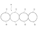
- FIG. 1 shows a schematic plane of a cylinder head gasket 11 according to an embodiment of the present invention.
- the cylinder head gasket 11 according to this embodiment is a flat metal cylinder head gasket that is sandwiched and mounted between a cylinder block and a cylinder head of an internal combustion engine, and is configured as follows.
- a required number of planar circular bore holes 12 are provided on the plane of the cylinder head gasket 11 and overlapped with the combustion chamber in the cylinder block according to the number of cylinders of the internal combustion engine.
- a portion (partition overlapping portion) 13 that overlaps the partition wall between the combustion chamber and the water jacket portion in the cylinder block
- a portion (W / J overlap portion) 14 that overlaps the water jacket portion in the cylinder block
- a portion (outer peripheral overlapping portion) 15 that is overlapped with the outer peripheral portion of the block in the cylinder block is sequentially provided in a planar manner.
- the partition overlapping portion 13 is formed in a concentric shape with respect to the planar circular bore hole 12 corresponding to the cylindrical partition wall in the cylinder block, and has a constant width (radial width) w. It is formed as a region.
- a surface pressure generating portion 16 having a three-dimensional shape is provided on the partition overlapping portion 13 so as to surround the bore hole 12.
- the surface pressure generator 16 includes an inner first surface pressure generator 16A as a bore seal that seals high-pressure gas in the combustion chamber, and an outer second surface as a water seal that seals cooling water in the water jacket portion. It is a combination with the pressure generating part 16B and forms a double seal line.
- the outer circumferential overlapping portion 15 is provided with a third surface pressure generating portion 17 having a three-dimensional shape so as to surround the W / J overlapping portion 14. Further, a bolt hole 18, a water / oil hole (not shown), a surface pressure generating portion (not shown) surrounding these, and the like are separately provided.
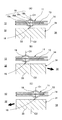
- the inner first surface pressure generating portion 16A among the surface pressure generating portions 16 provided in the partition overlapping portion 13 is formed so as to individually surround the plurality of bore holes 12, and is shown in the cross-sectional view of FIG. Thus, it is formed as a full bead 19 made of a combination of a pair of slopes 19a, 19b.
- the outer second surface pressure generating portion 16B is formed so as to collectively surround the plurality of bore holes 12, and as a half bead 20 comprising a combination of the inclined surface 20a and the flat surface 20b as shown in the sectional view of FIG. Is formed.
- the first and second surface pressure generating portions 16A and 16B are arranged at an intermediate position C2 where the intermediate position C1 is a fixed position in the thickness direction of the partition wall 33 in the cylinder block 31. ing.
- the intermediate position C 1 is disposed closer to the combustion chamber 32 than the intermediate position C 2 in the thickness direction of the partition wall 33, or on the circumference around the bore hole 12.
- the intermediate position C ⁇ b> 1 is arranged closer to the water jacket portion 34 than the intermediate position C ⁇ b> 2 in the thickness direction of the partition wall 33.
- the partition wall 33 in the cylinder block 31 may be deformed so as to fall to the combustion chamber 32 side as indicated by an arrow in FIG.
- the intermediate position C1 of the first and second surface pressure generating portions 16A and 16B closer to the water jacket portion 34 than the intermediate position C2 in the thickness direction of the partition wall 33, the degree of collapse of the partition wall 33 is reduced. Is possible.
- the partition wall 33 on the left side of the four partition walls 33 arranged in FIG. 3 the partition wall 33 is located near the water jacket portion 34 side (outside) in the vicinity of the 12 o'clock position and the 6 o'clock position.
- a bore deformation occurs that causes the partition wall 33 to fall and deform toward the combustion chamber 32 (inner side) near the 9 o'clock position. Therefore, an intermediate position C1 between the first and second surface pressure generating portions 16A and 16B is disposed closer to the combustion chamber 32 side (inner side) than the intermediate position C2 in the thickness direction of the partition wall 33 in the vicinity of the 12 o'clock position and in the vicinity of the 6 o'clock position. That is, the state shown in FIG.
- an intermediate position C1 between the first and second surface pressure generating portions 16A, 16B is disposed on the water jacket portion 34 side (outside) from the intermediate position C2 in the thickness direction of the partition wall 33. That is, the state shown in FIG.
- the intermediate position C1 between the first and second surface pressure generating portions 16A and 16B is the thickness direction of the partition wall 33. Arranged in the same way as the intermediate position C2. That is, the state shown in FIG.
- an intermediate position C1 between the first and second surface pressure generating portions 16A and 16B is disposed closer to the combustion chamber 32 side (inner side) than the intermediate position C2 in the thickness direction of the partition wall 33 in the vicinity of the 12 o'clock position and in the vicinity of the 6 o'clock position. That is, the state shown in FIG.
- an intermediate position C1 between the first and second surface pressure generating portions 16A and 16B is disposed on the combustion chamber 32 side (inside) from the intermediate position C2 in the thickness direction of the partition wall 33. That is, the state shown in FIG.
- the maximum surface pressure is generated at the top portion 19c or the bottom portion 19d between the pair of inclined surfaces 19a and 19b, so that the full bead is used with the top portion 19c or the bottom portion 19d as a reference for the position. 19 arrangements are determined. Further, in the half bead 20 constituting the second surface pressure generating portion 16B, the maximum surface pressure is generated at the corner portion 20c between the inclined surface 20a and the flat surface 20b. Therefore, the arrangement of the half beads 20 is determined using the corner portion 20c as a position reference. .
- the intermediate position C1 between the first and second surface pressure generating portions 16A and 16B refers to the intermediate position between the top 19c or bottom 19d of the full bead 19 and the corner 20c of the half bead 20 in this embodiment.
- the surface pressure generating portion is a shim welded (or folded) stopper and forms a step due to a thickness difference (stopper type)
- the arrangement is determined using the step as a position reference.
- FIG. 4 shows a case where the surface pressure generating portion 16 forms a single seal line instead of a double.
- the only three-dimensional shape that constitutes the surface pressure generating portion 16 is arranged on a part of the circumference on the combustion chamber 32 side or the water jacket portion 34 side from the middle position C2 in the thickness direction of the partition wall 33. Since the illustrated example is the full bead 19, the arrangement of the full bead 19 is determined using the top 19c or the bottom 19d between the pair of inclined surfaces 19a and 19b as a reference for the position.
- the intermediate position (constant position) C2 in the thickness direction of the partition wall 33 described above is Can also be described as the intermediate position (constant position) in the width direction of the partition wall 13. That is, even if the intermediate position C1 of the surface pressure generating portion 16 in the gasket 11 is displaced toward the combustion chamber 32 side or the water jacket portion 34 side with respect to the intermediate position C2 in the thickness direction of the partition wall 33, The intermediate position in the width direction of the partition wall overlapping portion 13 in the gasket 11 with respect to the position C2 is not displaced and is always arranged at the same position.
- the fact that the intermediate position C1 of the surface pressure generating portion 16 in the gasket 11 is displaced toward the combustion chamber 32 side or the water jacket portion 34 side with respect to the intermediate position C2 in the thickness direction of the partition wall 33 is This means that the intermediate position C1 of the surface pressure generating portion 16 in the gasket 11 is displaced toward the combustion chamber 32 side or the water jacket portion 34 side with respect to the intermediate position in the width direction.
- the surface pressure generating portion or the surface pressure generating point is a portion where the maximum surface pressure is generated when a load is applied by tightening the assembly bolt. Therefore, the surface pressure generation part or the surface pressure generation point described in the above description can be referred to as a load part or a load point.
- the state of occurrence of bore deformation in which the partition wall 33 between the combustion chamber 32 and the water jacket portion 34 in the cylinder block 31 falls down and deforms differs depending on the engine specifications.
- the engine for assembling the head gasket 11 is specified (selected).
- a conventional surface pressure generating portion 55 is arranged at the middle position in the thickness direction of the partition wall 33 between the cylinder block 31 and the cylinder head of the specified engine.
- the cylinder head gasket 51 is assembled and tightened with bolts to measure the occurrence of bore deformation.
- the incometer 41 is used, and the gauge 42 is brought into contact with the inner surface of the partition wall (bore side wall) 33 to make one round, and the unevenness is measured every 5 deg (can be arbitrarily set). To do.
- the gauge 42 is lowered by 5 mm (can be set arbitrarily), the gauge 42 is similarly applied to the inner surface of the partition wall 33 to make one turn, and the unevenness is measured every 5 deg.
- the degree of falling of the partition wall 33 is obtained as an actual measurement value.
- the intermediate position C1 between the first and second surface pressure generating portions 16A and 16B is the middle in the thickness direction of the partition wall 33 at the portion where the partition wall 33 is tilted and deformed toward the water jacket portion 34. It is designed to be positioned closer to the combustion chamber 32 than the position C2.
- the intermediate position C1 of the first and second surface pressure generators 16A, 16B is more water than the intermediate position C2 in the thickness direction of the partition wall 33 at the part where the partition wall 33 falls and deforms toward the combustion chamber 32. It is designed to be located on the jacket part 34 side.
- the other parts are also designed, and a design drawing of the entire gasket is created.
- the cylinder head gasket 11 is manufactured based on the created design drawing.
- the cylinder head gasket 11 that is optimal for reducing bore deformation for each engine specification, and according to tests conducted by the present inventors, the bore deformation is about 20-30%. It can be reduced at a rate.
- Cylinder head gasket 12 Bore hole 13 Bulkhead overlapping portion 14 W / J overlapping portion 15 Outer peripheral overlapping portion 16, 16A, 16B, 17 Surface pressure generating portion 18
- Cylinder block 32 Combustion chamber 33 Partition wall 34 Water jacket portion C1 Intermediate position between the first and second surface pressure generating portions C2 Intermediate position in the thickness direction of the partition wall
Landscapes
- Engineering & Computer Science (AREA)
- General Engineering & Computer Science (AREA)
- Mechanical Engineering (AREA)
- Chemical & Material Sciences (AREA)
- Combustion & Propulsion (AREA)
- Gasket Seals (AREA)
Abstract
面圧発生部におけるビードバネ定数の低減や段差量の低減に依存することなくボア変形を低減させるシリンダヘッドガスケットを提供する。この目的を達成するため、内燃機関のシリンダブロックおよびシリンダヘッド間に挟み込まれて装着されるシリンダヘッドガスケットであって、シリンダブロックにおける燃焼室に重ねられる部位に平面円形のボア穴を有するとともにシリンダブロックにおける燃焼室およびウォータージャケット部間の隔壁に重ねられる部位にボア穴の周りを囲む立体形状よりなる面圧発生部を有するシリンダヘッドガスケットにおいて、面圧発生部は、隔壁の厚み方向一定位置に配置されるとともにボア穴周りの円周上一部で隔壁の厚み方向一定位置より燃焼室側またはウォータージャケット部側に配置されている。
Description
本発明は、内燃機関のシリンダブロックおよびシリンダヘッド間に挟み込まれて装着されるシリンダヘッドガスケットとその製造方法に関する。
従来から図6に概略を示す平板状の金属製シリンダヘッドガスケット51が知られている。このシリンダヘッドガスケット51の平面上には、シリンダブロックにおける燃焼室に重ねられる部位に平面円形のボア穴52が気筒数に応じて所要数設けられ、またシリンダブロックにおける燃焼室およびウォータージャケット部間の隔壁に重ねられる部位(隔壁重ね部)53にボア穴52の周りを囲むビードまたは段差等の立体形状よりなる面圧発生部55が設けられている。
図6ではシリンダブロックにおけるウォータージャケット部に重ねられる部位(W/J重ね部)54を点線で描いている。このW/J重ね部54とボア穴52との間に隔壁重ね部53が設けられ、この隔壁重ね部53に図上一点鎖線で示す面圧発生部55が設けられている。また、ウォータージャケット部の冷却水がシリンダブロック外部へ洩れるのを防止するため、W/J重ね部54の外側にも面圧発生部56が設けられている。
隔壁重ね部53に設けられる面圧発生部55は、燃焼室の高圧ガスが洩れないようにシールするボア用シールとして設けられ、またウォータージャケット部の冷却水がボア側へ洩れないようにシールする水用シールとして設けられている。面圧発生部55の立体形状としてはビードよりなるもの(ビードタイプ)や、シム溶接(または折り返し)ストッパよりなり厚み差による段差を形成するもの(ストッパタイプ)などがある。
また、面圧発生部55はこのようにボア用シールおよび水用シールとして設けられるので二重のシールラインとして形成されることが多い。図6では内側の一点鎖線が前者のボア用シールとしての第1面圧発生部55Aを示し、外側の一点鎖線が後者の水用シールとしての第2面圧発生部55Bを示している。
第1面圧発生部55Aは、複数のボア穴52を個別に囲むように形成され、平面円形のボア穴52に対し同心円状に形成されている。第2面圧発生部55Bは複数のボア穴52をまとめて囲むように形成されるが、互いに隣り合うボア穴52同士の中間領域以外の部分については第1面圧発生部55Aと同様、平面円形のボア穴52に対し同心円状に形成されている。またこれらの第1および第2面圧発生部55A,55Bを設けた隔壁重ね部53はこれも平面円形のボア穴52に対し同心円状に形成され、一定の幅(径方向幅)wを備える環状の領域として形成されている。また、第1および第2面圧発生部55A,55Bはその中間位置が隔壁重ね部53の幅方向一定位置に配置され、隔壁重ね部53は隔壁に重ねられる部位であるので、第1および第2面圧発生部55A,55Bはその中間位置が隔壁の厚み方向一定位置に配置されるものとされている。
ところで、一般的にシリンダブロックおよびシリンダヘッド間にシリンダヘッドガスケット51を組み付けてボルトで締め付けると、ボルト締付け軸力入力に伴って発生する面圧発生部55の反力によりシリンダブロックが変形するいわゆるボア変形が発生する。これに対し、昨今における燃費向上の要求によりエンジンのフリクションを低減することすなわちボア変形を低減することが大きな課題となっている。
上記ボア変形を低減させるためには、上記ビードタイプではそのバネ定数を低くすること、ストッパタイプではその段差量を小さくすることが考えられる。
しかしながら燃費向上の要求はますます厳しくなってきており、更なるボア変形の低減のために更なるビードバネ定数の低減や段差量の低減を実施すると、シール面圧が益々低下し、シール性に支障を来たすことが懸念される。
本発明は以上の点に鑑みて、面圧発生部におけるビードバネ定数や段差量の低減などに依存することなくボア変形を低減させることができるシリンダヘッドガスケットとその製造方法を提供することを目的とする。
上記目的を達成するため、本発明の請求項1によるシリンダヘッドガスケットは、内燃機関のシリンダブロックおよびシリンダヘッド間に挟み込まれて装着されるシリンダヘッドガスケットであって、前記シリンダブロックにおける燃焼室に重ねられる部位に平面円形のボア穴を有するとともに前記シリンダブロックにおける燃焼室およびウォータージャケット部間の隔壁に重ねられる部位に前記ボア穴の周りを囲む立体形状よりなる面圧発生部を有するシリンダヘッドガスケットにおいて、前記面圧発生部は、前記隔壁の厚み方向一定位置に配置されるとともにボア穴周りの円周上一部で前記隔壁の厚み方向一定位置より燃焼室側またはウォータージャケット部側に配置されていることを特徴とする。
また、本発明の請求項2によるシリンダヘッドガスケットは、上記した請求項1記載のシリンダヘッドガスケットにおいて、前記面圧発生部は、ボア用シールとしての第1面圧発生部と水用シールとしての第2面圧発生部との組み合わせを有し、前記第1および第2面圧発生部の中間位置が前記隔壁の厚み方向一定位置に配置されるとともにボア穴周りの円周上一部で前記隔壁の厚み方向一定位置より燃焼室側またはウォータージャケット部側に配置されていることを特徴とする。
また、本発明の請求項3によるシリンダヘッドガスケットの製造方法は、上記した請求項1記載のシリンダヘッドガスケットを製造する方法であって、シリンダヘッドガスケットを装着するシリンダブロックに発生するボア変形を実測しまたはシミュレーションで予測する工程と、前記実測または予測の結果として前記シリンダブロックにおける燃焼室およびウォータージャケット部間の隔壁がウォータージャケット部側に倒れ変形する部位では面圧発生部が前記隔壁の厚み方向一定位置より燃焼室側に位置するように設計するとともに前記隔壁が燃焼室側に倒れ変形する部位では面圧発生部が前記隔壁の厚み方向一定位置よりウォータージャケット部側に位置するように設計する工程と、前記設計に基づいてシリンダヘッドガスケットを製作する工程とを順次実施することを特徴とする。
更にまた、本発明の請求項4によるシリンダヘッドガスケットの製造方法は、上記した請求項2記載のシリンダヘッドガスケットを製造する方法であって、シリンダヘッドガスケットを装着するシリンダブロックに発生するボア変形を実測しまたはシミュレーションで予測する工程と、前記実測または予測の結果として前記シリンダブロックにおける燃焼室およびウォータージャケット部間の隔壁がウォータージャケット部側に倒れ変形する部位では第1および第2面圧発生部の中間位置が前記隔壁の厚み方向一定位置より燃焼室側に位置するように設計するとともに前記隔壁が燃焼室側に倒れ変形する部位では第1および第2面圧発生部の中間位置が前記隔壁の厚み方向一定位置よりウォータージャケット部側に位置するように設計する工程と、前記設計に基づいてシリンダヘッドガスケットを製作する工程とを順次実施することを特徴とする。
上記したようにシリンダブロックおよびシリンダヘッド間にシリンダヘッドガスケットを組み付けてボルトで締め付けると、ボルト締付け軸力入力に伴って発生する面圧発生部の反力によりシリンダブロックが変形するいわゆるボア変形が発生することがあり、これに対し本発明はこのようなボア変形を低減することを課題とする。
ボア変形の態様としては、シリンダブロックにおける燃焼室およびウォータージャケット部間の隔壁がウォータージャケット部側に倒れるように変形することがある。この場合は、ガスケットにおける面圧発生部を隔壁の厚み方向一定位置より燃焼室側に配置することにより隔壁の倒れ度合いを縮小することが可能とされる。すなわち従来は面圧発生部を隔壁の厚み方向一定位置に配置していたため隔壁が或る量に亙ってウォータージャケット部側に倒れ変形していたところ、面圧発生部を隔壁の厚み方向一定位置よりウォータージャケット部側に移動させると隔壁の倒れ度合いが増大し、反対に面圧発生部を隔壁の厚み方向一定位置より燃焼室側に移動させると隔壁の倒れ度合いが縮小する。したがって本発明ではこの場合、後者を選択し、面圧発生部を隔壁の厚み方向一定位置より燃焼室側に配置する。
また、ボア変形の異なる態様としては、シリンダブロックにおける燃焼室およびウォータージャケット部間の隔壁が反対に燃焼室側に倒れるように変形することがある。この場合は、面圧発生部を隔壁の厚み方向一定位置よりウォータージャケット部側に配置することにより隔壁の倒れ度合いを縮小することが可能とされる。すなわち従来は面圧発生部を隔壁の厚み方向一定位置に配置していたため隔壁が或る量に亙って燃焼室側に倒れ変形していたところ、面圧発生部を隔壁の厚み方向一定位置より燃焼室側に移動させると隔壁の倒れ度合いが増大し、反対に面圧発生部を隔壁の厚み方向一定位置よりウォータージャケット部側に移動させると隔壁の倒れ度合いが縮小する。したがって本発明ではこの場合、後者を選択し、面圧発生部を隔壁の幅方向一定位置よりウォータージャケット部側に配置する。
尚、ボア変形はボア穴の周りの円周上一部で発生するので、これに合わせて本発明では上記したような面圧発生部の移動(径方向移動)をボア穴の周りの円周上一部のみにて行なうものである。ボア変形が発生していない部位まで面圧発生部を移動させると新たなボア変形が発生する要因ともなりかねず、このようなことは避けなければならない。
例えば平面円形のボア穴を時計の文字盤に見立てて、その12時位置近傍で隔壁が倒れ変形するボア変形が発生する場合には、この12時位置近傍のみにて面圧発生部を燃焼室側またはウォータージャケット部側に移動させ、残りの部分については面圧発生部を隔壁の厚み方向一定位置に配置し、12時位置近傍の面圧発生部と残りの部分の面圧発生部とをなだらかな曲線にて連結する。また、12時位置近傍および6時位置近傍でそれぞれ隔壁が倒れ変形するボア変形が発生する場合には、この12時位置近傍および6時位置近傍のみにて面圧発生部を燃焼室側またはウォータージャケット部側に移動させ、残りの部分については面圧発生部を隔壁の厚み方向一定位置に配置し、12時位置近傍および6時位置近傍の面圧発生部と残りの部分の面圧発生部とをなだらかな曲線にて連結する。したがって本発明では、ボア穴は平面円形であっても面圧発生部は同心状の円形とはならずに楕円形などの比較的いびつな形状となる。
また、面圧発生部としては上記したように、燃焼室の高圧ガスをシールするボア用シールとしての第1面圧発生部とウォータージャケット部の冷却水をシールする水用シールとしての第2面圧発生部があるビード形状の場合には、第1および第2面圧発生部の中間位置を隔壁の厚み方向一定位置に対し燃焼室側またはウォータージャケット部側に移動させる。したがって第1および第2面圧発生部は互いの間隔を一定に保ったままで移動することになる。
更にまた、隔壁が倒れ変形するボア変形の発生状況はエンジンの仕様ごとに異なるので、シリンダヘッドガスケットを製造するに際して先ずは、シリンダヘッドガスケットを組み付けるエンジンを特定(選択)する。次いで、特定したエンジンのシリンダブロックおよびシリンダヘッド間に従来タイプの面圧発生部を隔壁の厚み方向一定位置に配置したシリンダヘッドガスケットを組み付けボルトで締め付けてボア変形の発生状況を実測する。この実測はこれに代えてFEM解析などによるシミュレーションで予測値を採るようにしても良い。次いで、上記実測値または予測値に照らして面圧発生部の配置をボア穴の周りで全周に亙って決めていく。具体的には、隔壁がW/J側に倒れるように変形している場合には面圧発生部を隔壁の厚み方向一定位置よりも燃焼室側(内側)へ配置し、隔壁が燃焼室側に倒れるように変形している場合には面圧発生部を隔壁の厚み方向一定位置よりもウォータージャケット部側(外側)へ配置する。これをボア穴の周りで全周に亙って複数のポイントを決めて繰り返し、ポイントごとの面圧発生部の配置点を決定し、この面圧発生部の配置点をなだらかな曲線で結ぶと、真円形ではない楕円形のような全周に亙る面圧発生部の配置が決定される。次いで、決定した全周に亙る面圧発生部の配置に基づいてシリンダヘッドガスケットを製作する。したがって本発明によれば、エンジンの仕様ごとに最適なシリンダヘッドガスケットを製造することが可能とされる。
本発明は、以下の効果を奏する。
本発明においては、面圧発生部におけるビードバネ定数や段差量の低減などに依存することなくボア変形を低減させることができる。
本発明には、以下の実施形態が含まれる。
(1)従来のビードタイプまたはシム溶接(または折り返し)ストッパタイプのシリンダヘッドガスケットにおいてボア変形を低減させるためにビードタイプではバネ定数を低く、シム溶接(または折り返し)ストッパタイプでは段差量を小さくすることで対応している。しかしながら昨今における燃費向上要求はますます厳しくなってきており、更なるボア変形低減(=フリクション低減)のためのビードバネ定数低減、段差量低減が求められるが、何れもシール面圧低下の跳ね返り(副作用)があり、ボア変形低減にも限界がある。したがってシール面圧低下の跳ね返り(副作用)の無い対応技術が求められている。
(2)本発明では、シール面圧低下(=ビードバネ定数低減、段差量低減)の跳ね返り(副作用)が無くボア低減が可能な因子として面圧発生点(=荷重発生点)に着目し、バネ定数、段差量はそのままにその面圧発生点を場所により内側(ボア側)~外側(ウォータージャケット側)にボア変形が最小となるよう設定(可変化)する手法とした。
(3)ボア変形は、ボルト締付け軸力入力によりシリンダヘッドガスケットにおけるビード等の面圧発生部に反力が発生することでボア部(隔壁)に曲げモーメントが発生する現象である。またボア変形は、ボア(隔壁)にかかる曲げモーメント入力とその入力に耐えるボア剛性によって決定される。曲げモーメント入力は、ボアに発生するその荷重とその作用点(荷重点)とボルト位置で決まる作用長さにより決定され、シリンダヘッドガスケットは、その荷重と作用点(荷重点)位置に関わっている。本発明は、その荷重(シール面圧)はそのままに作用点(荷重点)を各気筒毎に変化させてボア変形低減を実現する。すなわち本発明は、面圧発生点(荷重発生点)が可変となる形状を備えるシリンダヘッドガスケットの発明である。
つぎに本発明の実施例を図面にしたがって説明する。
図1は、本発明の実施例に係るシリンダヘッドガスケット11の概略的な平面を示している。当該実施例に係るシリンダヘッドガスケット11は、内燃機関のシリンダブロックおよびシリンダヘッド間に挟み込まれて装着される平板状の金属製シリンダヘッドガスケットであって、以下のように構成されている。
すなわちシリンダヘッドガスケット11の平面上であってシリンダブロックにおける燃焼室に重ねられる部位に平面円形のボア穴12が内燃機関の気筒数に応じて所要数設けられている。このボア穴12の周りに、シリンダブロックにおける燃焼室およびウォータージャケット部間の隔壁に重ねられる部位(隔壁重ね部)13、シリンダブロックにおけるウォータージャケット部に重ねられる部位(W/J重ね部)14ならびにシリンダブロックにおけるブロック外周部に重ねられる部位(外周重ね部)15が順次平面的に設けられている。
このうち隔壁重ね部13は、シリンダブロックにおける隔壁が円筒状であるのに対応して平面円形のボア穴12に対し同心円状に形成され、かつ一定の幅(径方向幅)wを備える環状の領域として形成されている。この隔壁重ね部13にボア穴12の周りを囲むようにして立体形状よりなる面圧発生部16が設けられている。
面圧発生部16は、燃焼室の高圧ガスをシールするボア用シールとしての内側の第1面圧発生部16Aと、ウォータージャケット部の冷却水をシールする水用シールとしての外側の第2面圧発生部16Bとの組み合わせとされ、2重のシールラインを形成している。
外周重ね部15には、W/J重ね部14の周りを囲むようにして立体形状よりなる第3面圧発生部17が設けられている。また、ボルト穴18や水・油穴(図示せず)、これらを囲む面圧発生部(図示せず)などが別途設けられている。
隔壁重ね部13に設けられた面圧発生部16のうち内側の第1面圧発生部16Aは、複数のボア穴12を個別に囲むように形成され、図2(A)の断面図に示すように一対の斜面19a,19bの組み合わせよりなるフルビード19として形成されている。一方、外側の第2面圧発生部16Bは複数のボア穴12をまとめて囲むように形成され、図2(A)の断面図に示すように斜面20aおよび平面20bの組み合わせよりなるハーフビード20として形成されている。
また、この第1および第2面圧発生部16A,16Bは、図2(A)に示すようにその中間位置C1がシリンダブロック31における隔壁33の厚み方向一定位置としての中間位置C2に配置されている。ボア穴12周りの円周上一部では図2(B)に示すように中間位置C1が隔壁33の厚み方向中間位置C2より燃焼室32側に配置され、またはボア穴12周りの円周上一部では図2(C)に示すように中間位置C1が隔壁33の厚み方向中間位置C2よりウォータージャケット部34側に配置されている。これによりシリンダブロック31に発生するボア変形を低減することが可能とされている。
すなわち上記したようにシリンダブロックおよびシリンダヘッド間にシリンダヘッドガスケットを組み付けてボルトで締め付けると、ボルト締付け軸力入力に伴って発生する面圧発生部の反力によりシリンダブロックが変形するいわゆるボア変形が発生することがある。
ボア変形としては、図2(B)に矢印で示すようにシリンダブロック31における隔壁33がウォータージャケット部34側に倒れるように変形することがある。この場合には、ガスケット11における第1および第2面圧発生部16A,16Bの中間位置C1を隔壁33の厚み方向中間位置C2より燃焼室32側に配置することにより隔壁33の倒れ度合いを縮小することが可能とされる。
また、ボア変形としては、図2(C)に矢印で示すようにシリンダブロック31における隔壁33が燃焼室32側に倒れるように変形することがある。この場合には、第1および第2面圧発生部16A,16Bの中間位置C1を隔壁33の厚み方向中間位置C2よりウォータージャケット部34側に配置することにより隔壁33の倒れ度合いを縮小することが可能とされる。
例えば図3で4つ並んだ隔壁33のうち左側の隔壁33では、これを時計の文字盤に見立てて、その12時位置近傍および6時位置近傍で隔壁33がウォータージャケット部34側(外側)に倒れ変形するボア変形が発生するとともに、その9時位置近傍で隔壁33が燃焼室32側(内側)に倒れ変形するボア変形が発生する。したがって12時位置近傍および6時位置近傍で第1および第2面圧発生部16A,16Bの中間位置C1が、隔壁33の厚み方向中間位置C2より燃焼室32側(内側)に配置される。すなわち、図2(B)の状態になる。そして、9時位置近傍で第1および第2面圧発生部16A,16Bの中間位置C1が、隔壁33の厚み方向中間位置C2よりウォータージャケット部34側(外側)に配置される。すなわち、図2(C)の状態になる。
図3で4つ並んだ隔壁33のうち左から2番目の隔壁33では特にボア変形が発生しないので、第1および第2面圧発生部16A,16Bの中間位置C1は、隔壁33の厚み方向中間位置C2と同じに配置される。すなわち、図2(A)の状態になる。
図3で4つ並んだ隔壁33のうち左から3番目の隔壁33では、その12時位置近傍および6時位置近傍で隔壁33がウォータージャケット部34側(外側)に倒れ変形するボア変形が発生する。したがって12時位置近傍および6時位置近傍で第1および第2面圧発生部16A,16Bの中間位置C1が、隔壁33の厚み方向中間位置C2より燃焼室32側(内側)に配置される。すなわち、図2(B)の状態になる。
また、図3で4つ並んだ隔壁33のうち右側の隔壁33では、その12時位置近傍および6時位置近傍で隔壁33が燃焼室32側(内側)に倒れ変形するボア変形が発生するとともに、その3時位置近傍で隔壁33がウォータージャケット部34側(外側)に倒れ変形するボア変形が発生する。したがって12時位置近傍および6時位置近傍で第1および第2面圧発生部16A,16Bの中間位置C1が隔壁33の厚み方向中間位置C2よりウォータージャケット部34側(外側)に配置される。すなわち、図2(C)の状態になる。そして、3時位置近傍で第1および第2面圧発生部16A,16Bの中間位置C1が、隔壁33の厚み方向中間位置C2より燃焼室32側(内側)に配置される。すなわち、図2(B)の状態になる。
したがってこれらにより4つ並んだ隔壁33のそれぞれでその倒れ度合いを縮小することが可能とされる。
尚、第1面圧発生部16Aを構成するフルビード19では、一対の斜面19a,19b間の頂部19cまたは底部19dで最大面圧が発生するので、この頂部19cまたは底部19dを位置の基準としてフルビード19の配置を決定する。また第2面圧発生部16Bを構成するハーフビード20では、斜面20aおよび平面20b間の角部20cで最大面圧が発生するので、この角部20cを位置の基準としてハーフビード20の配置を決定する。したがって第1および第2面圧発生部16A,16Bの中間位置C1は当該実施例の場合、フルビード19の頂部19cまたは底部19dとハーフビード20の角部20cとの中間位置のことを云う。また図示はしないが、面圧発生部がシム溶接(または折り返し)ストッパよりなり厚み差による段差を形成するもの(ストッパタイプ)である場合には、段差を位置の基準として配置を決定する。
次に、本発明の他の実施例を図面にしたがって説明する。
面圧発生部16が2重ではなく1重のシールラインを形成する場合を図4に示す。ボア変形の方向により、この面圧発生部16を構成する唯一の立体形状を円周上一部で隔壁33の厚み方向中間位置C2より燃焼室32側またはウォータージャケット部34側に配置する。図示する例はフルビード19であるので、その一対の斜面19a,19b間の頂部19cまたは底部19dを位置の基準としてフルビード19の配置を決定することになる。
面圧発生部16が2重ではなく1重のシールラインを形成する場合を図4に示す。ボア変形の方向により、この面圧発生部16を構成する唯一の立体形状を円周上一部で隔壁33の厚み方向中間位置C2より燃焼室32側またはウォータージャケット部34側に配置する。図示する例はフルビード19であるので、その一対の斜面19a,19b間の頂部19cまたは底部19dを位置の基準としてフルビード19の配置を決定することになる。
また、隔壁33の厚み方向中間位置C2と隔壁重ね部13の幅方向中間位置はその位置が常に一致するので、これまでの説明で記載した隔壁33の厚み方向中間位置(一定位置)C2はこれを隔壁重ね部13の幅方向中間位置(一定位置)として説明することもできる。
すなわち、隔壁33の厚み方向中間位置C2に対しガスケット11における面圧発生部16の中間位置C1が燃焼室32側またはウォータージャケット部34側へ変位して配置されても、隔壁33の厚み方向中間位置C2に対しガスケット11における隔壁重ね部13の幅方向中間位置は変位せず常に同じ位置に配置される。したがって、隔壁33の厚み方向中間位置C2に対しガスケット11における面圧発生部16の中間位置C1を燃焼室32側またはウォータージャケット部34側へ変位して配置すると云うことは、隔壁重ね部13の幅方向中間位置に対しガスケット11における面圧発生部16の中間位置C1を燃焼室32側またはウォータージャケット部34側へ変位して配置すると云うことと同義である。
すなわち、隔壁33の厚み方向中間位置C2に対しガスケット11における面圧発生部16の中間位置C1が燃焼室32側またはウォータージャケット部34側へ変位して配置されても、隔壁33の厚み方向中間位置C2に対しガスケット11における隔壁重ね部13の幅方向中間位置は変位せず常に同じ位置に配置される。したがって、隔壁33の厚み方向中間位置C2に対しガスケット11における面圧発生部16の中間位置C1を燃焼室32側またはウォータージャケット部34側へ変位して配置すると云うことは、隔壁重ね部13の幅方向中間位置に対しガスケット11における面圧発生部16の中間位置C1を燃焼室32側またはウォータージャケット部34側へ変位して配置すると云うことと同義である。
また、面圧発生部ないし面圧発生点は、組付けボルトの締め付けにより荷重が作用することによって最大面圧が発生する部位である。したがって、これまでの説明で記載した面圧発生部ないし面圧発生点はこれを荷重部ないし荷重点と換言することができる。
つぎに上記構成のシリンダヘッドガスケット11の製造方法を説明する。
上記したようにシリンダブロック31における燃焼室32およびウォータージャケット部34間の隔壁33が倒れ変形するボア変形の発生状況はエンジンの仕様ごとに異なるので、シリンダヘッドガスケット11を製造するに際しては先ず、シリンダヘッドガスケット11を組み付けるエンジンを特定(選択)する。
次いで、特定したエンジンにどのようなボア変形が発生するかを測定し、すなわち特定したエンジンのシリンダブロック31およびシリンダヘッド間に従来タイプの面圧発生部55を隔壁33の厚み方向中間位置に配置したシリンダヘッドガスケット51を組み付け、ボルトで締め付けて、ボア変形の発生状況を実測する。
実測法としては例えば図5に示すようにインコメータ41を用いて行ない、ゲージ42を隔壁(ボア側壁)33の内面に当てて1周させ、5deg毎(任意に設定可)にその凹凸を測定する。次にゲージ42を5mm下げた(任意に設定可)ところで同様にゲージ42を隔壁33の内面に当てて1周させ、5deg毎にその凹凸を測定し、これを隔壁33の下部まで繰り返し実施することにより隔壁33の倒れ度合いを実測値として知得する。
次いで、上記実測値に照らして、面圧発生部16の配置を決定する設計を行なう。すなわち、図2(B)に示すように隔壁33がウォータージャケット部34側に倒れ変形している部位では第1および第2面圧発生部16A,16Bの中間位置C1が隔壁33の厚み方向中間位置C2より燃焼室32側に位置するように設計する。図2(C)に示すように隔壁33が燃焼室32側に倒れ変形する部位では、第1および第2面圧発生部16A,16Bの中間位置C1が隔壁33の厚み方向中間位置C2よりウォータージャケット部34側に位置するように設計する。その他の部位についても併せ設計し、ガスケット全体の設計図を作成する。
次いで、作成した設計図に基づいてシリンダヘッドガスケット11を製作する。
したがってこの製造方法によれば、エンジンの仕様ごとにボア変形の低減について最適なシリンダヘッドガスケット11を製造することができ、本願発明者らが行なった試験によるとボア変形を約20~30%の割合で低減することができる。
11 シリンダヘッドガスケット
12 ボア穴
13 隔壁重ね部
14 W/J重ね部
15 外周重ね部
16,16A,16B,17 面圧発生部
18 ボルト穴
19 フルビード
19a,19b,20a 斜面
19c 頂部
19d 底部
20 ハーフビード
20b 平面
20c 角部
31 シリンダブロック
32 燃焼室
33 隔壁
34ウォータージャケット部
C1 第1および第2面圧発生部の中間位置
C2 隔壁の厚み方向中間位置
12 ボア穴
13 隔壁重ね部
14 W/J重ね部
15 外周重ね部
16,16A,16B,17 面圧発生部
18 ボルト穴
19 フルビード
19a,19b,20a 斜面
19c 頂部
19d 底部
20 ハーフビード
20b 平面
20c 角部
31 シリンダブロック
32 燃焼室
33 隔壁
34ウォータージャケット部
C1 第1および第2面圧発生部の中間位置
C2 隔壁の厚み方向中間位置
Claims (4)
- 内燃機関のシリンダブロックおよびシリンダヘッド間に挟み込まれて装着されるシリンダヘッドガスケットであって、前記シリンダブロックにおける燃焼室に重ねられる部位に平面円形のボア穴を有するとともに前記シリンダブロックにおける燃焼室およびウォータージャケット部間の隔壁に重ねられる部位に前記ボア穴の周りを囲む立体形状よりなる面圧発生部を有するシリンダヘッドガスケットにおいて、
前記面圧発生部は、前記隔壁の厚み方向一定位置に配置されるとともにボア穴周りの円周上一部で前記隔壁の厚み方向一定位置より燃焼室側またはウォータージャケット部側に配置されていることを特徴とするシリンダヘッドガスケット。 - 請求項1記載のシリンダヘッドガスケットにおいて、
前記面圧発生部は、ボア用シールとしての第1面圧発生部と水用シールとしての第2面圧発生部との組み合わせを有し、
前記第1および第2面圧発生部の中間位置が前記隔壁の厚み方向一定位置に配置されるとともにボア穴周りの円周上一部で前記隔壁の厚み方向一定位置より燃焼室側またはウォータージャケット部側に配置されていることを特徴とするシリンダヘッドガスケット。 - 請求項1記載のシリンダヘッドガスケットを製造する方法であって、
シリンダヘッドガスケットを装着するシリンダブロックに発生するボア変形を実測しまたはシミュレーションで予測する工程と、
前記実測または予測の結果として前記シリンダブロックにおける燃焼室およびウォータージャケット部間の隔壁がウォータージャケット部側に倒れ変形する部位では面圧発生部が前記隔壁の厚み方向一定位置より燃焼室側に位置するように設計するとともに前記隔壁が燃焼室側に倒れ変形する部位では面圧発生部が前記隔壁の厚み方向一定位置よりウォータージャケット部側に位置するように設計する工程と、
前記設計に基づいてシリンダヘッドガスケットを製作する工程とを順次実施することを特徴とするシリンダヘッドガスケットの製造方法。 - 請求項2記載のシリンダヘッドガスケットを製造する方法であって、
シリンダヘッドガスケットを装着するシリンダブロックに発生するボア変形を実測しまたはシミュレーションで予測する工程と、
前記実測または予測の結果として前記シリンダブロックにおける燃焼室およびウォータージャケット部間の隔壁がウォータージャケット部側に倒れ変形する部位では第1および第2面圧発生部の中間位置が前記隔壁の厚み方向一定位置より燃焼室側に位置するように設計するとともに前記隔壁が燃焼室側に倒れ変形する部位では第1および第2面圧発生部の中間位置が前記隔壁の厚み方向一定位置よりウォータージャケット部側に位置するように設計する工程と、
前記設計に基づいてシリンダヘッドガスケットを製作する工程とを順次実施することを特徴とするシリンダヘッドガスケットの製造方法。
Priority Applications (3)
| Application Number | Priority Date | Filing Date | Title |
|---|---|---|---|
| US15/100,537 US10184424B2 (en) | 2013-12-18 | 2014-12-10 | Cylinder head gasket and method of manufacturing the same |
| CN201480068572.1A CN105829781B (zh) | 2013-12-18 | 2014-12-10 | 气缸盖衬垫及其制造方法 |
| EP14872304.2A EP3086004B1 (en) | 2013-12-18 | 2014-12-10 | Cylinder head gasket and method for manufacturing same |
Applications Claiming Priority (2)
| Application Number | Priority Date | Filing Date | Title |
|---|---|---|---|
| JP2013261021A JP6259276B2 (ja) | 2013-12-18 | 2013-12-18 | シリンダヘッドガスケット及びその製造方法 |
| JP2013-261021 | 2013-12-18 |
Publications (1)
| Publication Number | Publication Date |
|---|---|
| WO2015093368A1 true WO2015093368A1 (ja) | 2015-06-25 |
Family
ID=53402717
Family Applications (1)
| Application Number | Title | Priority Date | Filing Date |
|---|---|---|---|
| PCT/JP2014/082678 Ceased WO2015093368A1 (ja) | 2013-12-18 | 2014-12-10 | シリンダヘッドガスケット及びその製造方法 |
Country Status (5)
| Country | Link |
|---|---|
| US (1) | US10184424B2 (ja) |
| EP (1) | EP3086004B1 (ja) |
| JP (1) | JP6259276B2 (ja) |
| CN (1) | CN105829781B (ja) |
| WO (1) | WO2015093368A1 (ja) |
Families Citing this family (6)
| Publication number | Priority date | Publication date | Assignee | Title |
|---|---|---|---|---|
| JP2018071730A (ja) | 2016-11-02 | 2018-05-10 | Nok株式会社 | ガスケット |
| US11774187B2 (en) * | 2018-04-19 | 2023-10-03 | Kyungdong Navien Co., Ltd. | Heat transfer fin of fin-tube type heat exchanger |
| KR20200068989A (ko) * | 2018-12-06 | 2020-06-16 | 현대자동차주식회사 | 실린더블록용 워터재킷의 내장 구조물 |
| KR20210037051A (ko) * | 2019-09-26 | 2021-04-06 | 현대자동차주식회사 | 실린더라이너 및 그 실린더라이너가 결합된 실린더블록 |
| US11635143B2 (en) * | 2019-10-14 | 2023-04-25 | Dana Automotive Systems Group, Llc | Multi-layer gasket with improved fatigue resistance |
| CN115555811B (zh) * | 2022-10-27 | 2025-05-06 | 山西柴油机工业有限责任公司 | 一种单缸发动机气缸盖的加工方法 |
Citations (4)
| Publication number | Priority date | Publication date | Assignee | Title |
|---|---|---|---|---|
| JPH0573361U (ja) * | 1991-02-25 | 1993-10-08 | 石川ガスケット株式会社 | 金属積層形シリンダヘッドガスケット |
| JPH1193763A (ja) * | 1997-09-19 | 1999-04-06 | Suzuki Motor Corp | エンジンのシール構造 |
| JP2006161915A (ja) * | 2004-12-06 | 2006-06-22 | Ishikawa Gasket Co Ltd | メタルガスケット |
| JP2006342749A (ja) | 2005-06-09 | 2006-12-21 | Nippon Gasket Co Ltd | 金属ガスケット |
Family Cites Families (14)
| Publication number | Priority date | Publication date | Assignee | Title |
|---|---|---|---|---|
| EP0369033B1 (en) | 1988-05-27 | 1995-11-15 | TERAI, Toshimitsu | Metal gasket |
| JP3197395B2 (ja) | 1993-01-14 | 2001-08-13 | 日本メタルガスケット株式会社 | 金属ガスケット |
| JP3230966B2 (ja) | 1995-10-09 | 2001-11-19 | 日本ガスケット株式会社 | 金属製ガスケット |
| US5853175A (en) * | 1996-09-30 | 1998-12-29 | Ishikawa Gasket Co., Ltd. | Cylinder head gasket with fluid flow path |
| US6139025A (en) * | 1997-07-17 | 2000-10-31 | Ishikawa Gasket Co., Ltd. | Metal laminate gasket with wide and narrow flange portions |
| JP3098734B2 (ja) | 1997-10-13 | 2000-10-16 | 石川ガスケット株式会社 | 金属積層形ガスケット |
| JP2000074219A (ja) | 1998-08-27 | 2000-03-14 | Nippon Gasket Co Ltd | 金属製ガスケット |
| EP1457718B1 (en) * | 2003-03-14 | 2011-10-05 | Renault S.A.S. | Cylinder head gasket arrangements for engine assemblies |
| US7234705B2 (en) * | 2003-08-28 | 2007-06-26 | Freudenberg-Nok General Partnership | Sealing gasket with flexible stopper |
| JP3946218B2 (ja) * | 2004-11-10 | 2007-07-18 | 石川ガスケット株式会社 | 金属ガスケット |
| EP1677034A1 (de) * | 2004-12-14 | 2006-07-05 | Carl Freudenberg KG | Dichtung mit Begrenzungsbereich |
| JP4845833B2 (ja) * | 2007-08-10 | 2011-12-28 | エルリングクリンガー・マルサン株式会社 | メタルガスケット |
| US8632077B2 (en) * | 2008-02-13 | 2014-01-21 | Federal-Mogul Corporation | Multilayer static gasket with bead compression limiter |
| CN105612372B (zh) * | 2013-09-10 | 2018-08-07 | 费德罗-莫格尔公司 | 无涂层汽缸头垫片 |
-
2013
- 2013-12-18 JP JP2013261021A patent/JP6259276B2/ja active Active
-
2014
- 2014-12-10 EP EP14872304.2A patent/EP3086004B1/en active Active
- 2014-12-10 US US15/100,537 patent/US10184424B2/en active Active
- 2014-12-10 WO PCT/JP2014/082678 patent/WO2015093368A1/ja not_active Ceased
- 2014-12-10 CN CN201480068572.1A patent/CN105829781B/zh active Active
Patent Citations (4)
| Publication number | Priority date | Publication date | Assignee | Title |
|---|---|---|---|---|
| JPH0573361U (ja) * | 1991-02-25 | 1993-10-08 | 石川ガスケット株式会社 | 金属積層形シリンダヘッドガスケット |
| JPH1193763A (ja) * | 1997-09-19 | 1999-04-06 | Suzuki Motor Corp | エンジンのシール構造 |
| JP2006161915A (ja) * | 2004-12-06 | 2006-06-22 | Ishikawa Gasket Co Ltd | メタルガスケット |
| JP2006342749A (ja) | 2005-06-09 | 2006-12-21 | Nippon Gasket Co Ltd | 金属ガスケット |
Also Published As
| Publication number | Publication date |
|---|---|
| US20160298573A1 (en) | 2016-10-13 |
| JP6259276B2 (ja) | 2018-01-10 |
| EP3086004A4 (en) | 2016-11-23 |
| EP3086004B1 (en) | 2018-02-14 |
| JP2015117757A (ja) | 2015-06-25 |
| US10184424B2 (en) | 2019-01-22 |
| CN105829781B (zh) | 2019-02-12 |
| CN105829781A (zh) | 2016-08-03 |
| EP3086004A1 (en) | 2016-10-26 |
Similar Documents
| Publication | Publication Date | Title |
|---|---|---|
| JP6259276B2 (ja) | シリンダヘッドガスケット及びその製造方法 | |
| CN105190129B (zh) | 主燃烧密封凸起内的小弹性密封特征 | |
| US9284913B2 (en) | Metal gasket | |
| JP5136808B2 (ja) | シリンダヘッドガスケットとその製造方法 | |
| US7137631B2 (en) | Cylinder head gasket | |
| US9574516B2 (en) | Engine having cylinder block | |
| JP3989491B2 (ja) | シリンダヘッドガスケット | |
| JP6002022B2 (ja) | 金属ガスケット | |
| JP6450910B2 (ja) | 溶接ハイブリッドリングを備えるシリンダヘッドガスケット | |
| JP6408659B1 (ja) | ガスケット | |
| KR101992936B1 (ko) | 다층 스토퍼 구조를 가지는 실린더 헤드 가스켓 | |
| JP2011017434A (ja) | 金属ガスケット | |
| JP2005155713A (ja) | 金属ガスケット | |
| US20180266559A1 (en) | Flat gasket and sealing assembly containing a flat gasket | |
| JP7644175B2 (ja) | 内燃機関 | |
| JP7218685B2 (ja) | 内燃機関構造 | |
| JPH0526350A (ja) | 金属製ガスケツト | |
| JP2010038299A (ja) | 金属ガスケット | |
| EP1561975B1 (en) | Cylinder head gasket | |
| JP2009257107A (ja) | シリンダブロック冷却構造 | |
| JP5023102B2 (ja) | 金属製ガスケット及びその製造方法 | |
| JP2008064025A (ja) | オープンデッキ型のシリンダブロック | |
| JP4787343B2 (ja) | 金属製ガスケット及びその製造方法 | |
| CN112012845A (zh) | 具有多层止动结构的气缸盖垫片 | |
| KR20210043157A (ko) | 국부적인 코팅부에 의한 심스토퍼 구조물을 갖는 헤드가스켓 |
Legal Events
| Date | Code | Title | Description |
|---|---|---|---|
| 121 | Ep: the epo has been informed by wipo that ep was designated in this application |
Ref document number: 14872304 Country of ref document: EP Kind code of ref document: A1 |
|
| WWE | Wipo information: entry into national phase |
Ref document number: 15100537 Country of ref document: US |
|
| REEP | Request for entry into the european phase |
Ref document number: 2014872304 Country of ref document: EP |
|
| WWE | Wipo information: entry into national phase |
Ref document number: 2014872304 Country of ref document: EP |
|
| NENP | Non-entry into the national phase |
Ref country code: DE |