WO2015093494A1 - 電力制御装置、機器制御装置、及び方法 - Google Patents
電力制御装置、機器制御装置、及び方法 Download PDFInfo
- Publication number
- WO2015093494A1 WO2015093494A1 PCT/JP2014/083311 JP2014083311W WO2015093494A1 WO 2015093494 A1 WO2015093494 A1 WO 2015093494A1 JP 2014083311 W JP2014083311 W JP 2014083311W WO 2015093494 A1 WO2015093494 A1 WO 2015093494A1
- Authority
- WO
- WIPO (PCT)
- Prior art keywords
- power
- control device
- class
- power supply
- communication unit
- Prior art date
- Legal status (The legal status is an assumption and is not a legal conclusion. Google has not performed a legal analysis and makes no representation as to the accuracy of the status listed.)
- Ceased
Links
Images





Classifications
-
- H—ELECTRICITY
- H02—GENERATION; CONVERSION OR DISTRIBUTION OF ELECTRIC POWER
- H02J—ELECTRIC POWER NETWORKS; CIRCUIT ARRANGEMENTS OR SYSTEMS FOR SUPPLYING OR DISTRIBUTING ELECTRIC POWER; SYSTEMS FOR STORING ELECTRIC ENERGY
- H02J3/00—Circuit arrangements for AC mains or AC distribution networks
- H02J3/38—Arrangements for feeding a single network from two or more generators or sources in parallel; Arrangements for feeding already energised networks from additional generators or sources in parallel
- H02J3/381—Dispersed generators
-
- H—ELECTRICITY
- H02—GENERATION; CONVERSION OR DISTRIBUTION OF ELECTRIC POWER
- H02J—ELECTRIC POWER NETWORKS; CIRCUIT ARRANGEMENTS OR SYSTEMS FOR SUPPLYING OR DISTRIBUTING ELECTRIC POWER; SYSTEMS FOR STORING ELECTRIC ENERGY
- H02J13/00—Circuit arrangements for providing remote monitoring or remote control of equipment in a power distribution network
- H02J13/12—Monitoring network conditions, e.g. electrical magnitudes or operational status
-
- H—ELECTRICITY
- H02—GENERATION; CONVERSION OR DISTRIBUTION OF ELECTRIC POWER
- H02J—ELECTRIC POWER NETWORKS; CIRCUIT ARRANGEMENTS OR SYSTEMS FOR SUPPLYING OR DISTRIBUTING ELECTRIC POWER; SYSTEMS FOR STORING ELECTRIC ENERGY
- H02J13/00—Circuit arrangements for providing remote monitoring or remote control of equipment in a power distribution network
- H02J13/13—Circuit arrangements for providing remote monitoring or remote control of equipment in a power distribution network characterised by the transmission of data to equipment in the power network
-
- H—ELECTRICITY
- H02—GENERATION; CONVERSION OR DISTRIBUTION OF ELECTRIC POWER
- H02J—ELECTRIC POWER NETWORKS; CIRCUIT ARRANGEMENTS OR SYSTEMS FOR SUPPLYING OR DISTRIBUTING ELECTRIC POWER; SYSTEMS FOR STORING ELECTRIC ENERGY
- H02J7/00—Circuit arrangements for charging or discharging batteries or for supplying loads from batteries
- H02J7/34—Parallel operation in networks using both storage and other DC sources, e.g. providing buffering
- H02J7/35—Parallel operation in networks using both storage and other DC sources, e.g. providing buffering with light sensitive cells
-
- H—ELECTRICITY
- H02—GENERATION; CONVERSION OR DISTRIBUTION OF ELECTRIC POWER
- H02J—ELECTRIC POWER NETWORKS; CIRCUIT ARRANGEMENTS OR SYSTEMS FOR SUPPLYING OR DISTRIBUTING ELECTRIC POWER; SYSTEMS FOR STORING ELECTRIC ENERGY
- H02J2101/00—Supply or distribution of decentralised, dispersed or local electric power generation
- H02J2101/20—Dispersed power generation using renewable energy sources
- H02J2101/22—Solar energy
- H02J2101/24—Photovoltaics
-
- H—ELECTRICITY
- H02—GENERATION; CONVERSION OR DISTRIBUTION OF ELECTRIC POWER
- H02J—ELECTRIC POWER NETWORKS; CIRCUIT ARRANGEMENTS OR SYSTEMS FOR SUPPLYING OR DISTRIBUTING ELECTRIC POWER; SYSTEMS FOR STORING ELECTRIC ENERGY
- H02J7/00—Circuit arrangements for charging or discharging batteries or for supplying loads from batteries
- H02J7/40—Circuit arrangements for charging or discharging batteries or for supplying loads from batteries characterised by the exchange of charge or discharge related data
- H02J7/42—Circuit arrangements for charging or discharging batteries or for supplying loads from batteries characterised by the exchange of charge or discharge related data with electronic devices having internal batteries, e.g. mobile phones
-
- Y—GENERAL TAGGING OF NEW TECHNOLOGICAL DEVELOPMENTS; GENERAL TAGGING OF CROSS-SECTIONAL TECHNOLOGIES SPANNING OVER SEVERAL SECTIONS OF THE IPC; TECHNICAL SUBJECTS COVERED BY FORMER USPC CROSS-REFERENCE ART COLLECTIONS [XRACs] AND DIGESTS
- Y02—TECHNOLOGIES OR APPLICATIONS FOR MITIGATION OR ADAPTATION AGAINST CLIMATE CHANGE
- Y02E—REDUCTION OF GREENHOUSE GAS [GHG] EMISSIONS, RELATED TO ENERGY GENERATION, TRANSMISSION OR DISTRIBUTION
- Y02E10/00—Energy generation through renewable energy sources
- Y02E10/50—Photovoltaic [PV] energy
- Y02E10/56—Power conversion systems, e.g. maximum power point trackers
-
- Y—GENERAL TAGGING OF NEW TECHNOLOGICAL DEVELOPMENTS; GENERAL TAGGING OF CROSS-SECTIONAL TECHNOLOGIES SPANNING OVER SEVERAL SECTIONS OF THE IPC; TECHNICAL SUBJECTS COVERED BY FORMER USPC CROSS-REFERENCE ART COLLECTIONS [XRACs] AND DIGESTS
- Y02—TECHNOLOGIES OR APPLICATIONS FOR MITIGATION OR ADAPTATION AGAINST CLIMATE CHANGE
- Y02E—REDUCTION OF GREENHOUSE GAS [GHG] EMISSIONS, RELATED TO ENERGY GENERATION, TRANSMISSION OR DISTRIBUTION
- Y02E40/00—Technologies for an efficient electrical power generation, transmission or distribution
- Y02E40/70—Smart grids as climate change mitigation technology in the energy generation sector
-
- Y—GENERAL TAGGING OF NEW TECHNOLOGICAL DEVELOPMENTS; GENERAL TAGGING OF CROSS-SECTIONAL TECHNOLOGIES SPANNING OVER SEVERAL SECTIONS OF THE IPC; TECHNICAL SUBJECTS COVERED BY FORMER USPC CROSS-REFERENCE ART COLLECTIONS [XRACs] AND DIGESTS
- Y02—TECHNOLOGIES OR APPLICATIONS FOR MITIGATION OR ADAPTATION AGAINST CLIMATE CHANGE
- Y02E—REDUCTION OF GREENHOUSE GAS [GHG] EMISSIONS, RELATED TO ENERGY GENERATION, TRANSMISSION OR DISTRIBUTION
- Y02E60/00—Enabling technologies; Technologies with a potential or indirect contribution to GHG emissions mitigation
-
- Y—GENERAL TAGGING OF NEW TECHNOLOGICAL DEVELOPMENTS; GENERAL TAGGING OF CROSS-SECTIONAL TECHNOLOGIES SPANNING OVER SEVERAL SECTIONS OF THE IPC; TECHNICAL SUBJECTS COVERED BY FORMER USPC CROSS-REFERENCE ART COLLECTIONS [XRACs] AND DIGESTS
- Y02—TECHNOLOGIES OR APPLICATIONS FOR MITIGATION OR ADAPTATION AGAINST CLIMATE CHANGE
- Y02P—CLIMATE CHANGE MITIGATION TECHNOLOGIES IN THE PRODUCTION OR PROCESSING OF GOODS
- Y02P90/00—Enabling technologies with a potential contribution to greenhouse gas [GHG] emissions mitigation
- Y02P90/50—Energy storage in industry with an added climate change mitigation effect
-
- Y—GENERAL TAGGING OF NEW TECHNOLOGICAL DEVELOPMENTS; GENERAL TAGGING OF CROSS-SECTIONAL TECHNOLOGIES SPANNING OVER SEVERAL SECTIONS OF THE IPC; TECHNICAL SUBJECTS COVERED BY FORMER USPC CROSS-REFERENCE ART COLLECTIONS [XRACs] AND DIGESTS
- Y04—INFORMATION OR COMMUNICATION TECHNOLOGIES HAVING AN IMPACT ON OTHER TECHNOLOGY AREAS
- Y04S—SYSTEMS INTEGRATING TECHNOLOGIES RELATED TO POWER NETWORK OPERATION, COMMUNICATION OR INFORMATION TECHNOLOGIES FOR IMPROVING THE ELECTRICAL POWER GENERATION, TRANSMISSION, DISTRIBUTION, MANAGEMENT OR USAGE, i.e. SMART GRIDS
- Y04S10/00—Systems supporting electrical power generation, transmission or distribution
- Y04S10/12—Monitoring or controlling equipment for energy generation units, e.g. distributed energy generation [DER] or load-side generation
- Y04S10/123—Monitoring or controlling equipment for energy generation units, e.g. distributed energy generation [DER] or load-side generation the energy generation units being or involving renewable energy sources
-
- Y—GENERAL TAGGING OF NEW TECHNOLOGICAL DEVELOPMENTS; GENERAL TAGGING OF CROSS-SECTIONAL TECHNOLOGIES SPANNING OVER SEVERAL SECTIONS OF THE IPC; TECHNICAL SUBJECTS COVERED BY FORMER USPC CROSS-REFERENCE ART COLLECTIONS [XRACs] AND DIGESTS
- Y04—INFORMATION OR COMMUNICATION TECHNOLOGIES HAVING AN IMPACT ON OTHER TECHNOLOGY AREAS
- Y04S—SYSTEMS INTEGRATING TECHNOLOGIES RELATED TO POWER NETWORK OPERATION, COMMUNICATION OR INFORMATION TECHNOLOGIES FOR IMPROVING THE ELECTRICAL POWER GENERATION, TRANSMISSION, DISTRIBUTION, MANAGEMENT OR USAGE, i.e. SMART GRIDS
- Y04S10/00—Systems supporting electrical power generation, transmission or distribution
- Y04S10/30—State monitoring, e.g. fault, temperature monitoring, insulator monitoring, corona discharge
-
- Y—GENERAL TAGGING OF NEW TECHNOLOGICAL DEVELOPMENTS; GENERAL TAGGING OF CROSS-SECTIONAL TECHNOLOGIES SPANNING OVER SEVERAL SECTIONS OF THE IPC; TECHNICAL SUBJECTS COVERED BY FORMER USPC CROSS-REFERENCE ART COLLECTIONS [XRACs] AND DIGESTS
- Y04—INFORMATION OR COMMUNICATION TECHNOLOGIES HAVING AN IMPACT ON OTHER TECHNOLOGY AREAS
- Y04S—SYSTEMS INTEGRATING TECHNOLOGIES RELATED TO POWER NETWORK OPERATION, COMMUNICATION OR INFORMATION TECHNOLOGIES FOR IMPROVING THE ELECTRICAL POWER GENERATION, TRANSMISSION, DISTRIBUTION, MANAGEMENT OR USAGE, i.e. SMART GRIDS
- Y04S40/00—Systems for electrical power generation, transmission, distribution or end-user application management characterised by the use of communication or information technologies, or communication or information technology specific aspects supporting them
- Y04S40/12—Systems for electrical power generation, transmission, distribution or end-user application management characterised by the use of communication or information technologies, or communication or information technology specific aspects supporting them characterised by data transport means between the monitoring, controlling or managing units and monitored, controlled or operated electrical equipment
Definitions
- the present invention relates to a power control device, a device control device, and a method for performing communication according to a predetermined communication protocol.
- EMS Energy Management System
- ECHONET Lite (registered trademark), which is one of such communication protocols, specifies a device class for each type of device, and specifies for each device class the information and control target of the device as properties.
- the storage battery device belongs to a storage battery class, and the properties corresponding to the storage battery class include a storage battery capacity, a maximum and minimum charging power value, and the like (see Non-Patent Document 1).
- the plurality of power supply devices are a solar power generation device, a storage battery device, a fuel cell device, and the like.
- the power supply system described above is a new system that uses a combination of a plurality of power supply devices, and has a feature that does not exist in a conventional system that uses a power supply device alone.
- the power conversion loss can be reduced as compared with the conventional system that performs DC-AC conversion in the power supply device.
- the power control apparatus is provided in a customer facility and controls power supply from a plurality of power supply apparatuses.
- the power control device includes: a conversion unit capable of collectively converting DC power output from each of the plurality of power supply devices into AC; and a communication unit that performs communication with an external device control device according to a predetermined communication protocol. Prepare.
- the communication unit notifies the device control device of the device class of the power control device, in addition to notifying the device control device of the device class of each of the plurality of power supply devices.
- the device control apparatus controls a power control apparatus that can convert DC power output from each of the plurality of power supply apparatuses into AC.
- the device control device includes a communication unit that performs communication with the power control device according to a predetermined communication protocol, and a control unit that performs the control via the communication unit.
- the communication unit acquires a device class of the power control device from the power control device in addition to acquiring a device class of each of the plurality of power supply devices from the power control device.
- the method according to the third feature is used in a system including a plurality of power supply devices and a power control device capable of collectively converting DC power output from each of the plurality of power supply devices into AC.
- the power control device and the device control device communicate according to a predetermined communication protocol, and the device class of each of the plurality of power supply devices is transmitted from the power control device to the device control device in the communication.
- the device class of the power control apparatus is notified.
- FIG. 1 is a block diagram illustrating a configuration of a control system according to the first to sixth embodiments.
- FIG. 2 is a block diagram illustrating a configuration of the power control apparatus according to the first to sixth embodiments.
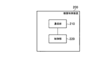
- FIG. 3 is a block diagram illustrating a configuration of the device control apparatus according to the first to sixth embodiments.
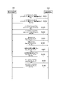
- FIG. 4 is a sequence diagram showing a node connection sequence according to the first embodiment.
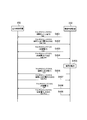
- FIG. 5 is a sequence diagram showing an operation according to the second embodiment.
- FIG. 6 is a sequence diagram showing an operation according to the third embodiment.
- FIG. 7 is a sequence diagram showing an operation according to the fourth embodiment.
- FIG. 8 is a sequence diagram showing an operation according to the fifth embodiment.
- the power control apparatus is provided in a customer facility and controls power supply from a plurality of power supply apparatuses.
- the power control device includes: a conversion unit capable of collectively converting DC power output from each of the plurality of power supply devices into AC; and a communication unit that performs communication with an external device control device according to a predetermined communication protocol. Prepare.
- the communication unit notifies the device control device of the device class of the power control device, in addition to notifying the device control device of the device class of each of the plurality of power supply devices.
- the plurality of power supply devices include a predetermined power supply device belonging to a predetermined device class defined to output AC power in the predetermined communication protocol.
- the communication unit can notify the device control device of an output parameter of the predetermined power supply device as a property corresponding to the predetermined device class.
- the communication unit notifies the device control apparatus of information indicating that the output parameter should be read as DC.
- the communication unit notifies the device control device of the rated output value of the conversion unit as a property corresponding to the device class of the power control device.
- the rated output value of the conversion unit is smaller than the total of the rated output values of the plurality of power supply devices.
- the communication unit receives a setting request transmitted from the device control apparatus in response to the notification of the rated output value.
- the setting request includes an output value for at least one of the plurality of power supply devices.
- the communication unit notifies the device control device of the instantaneous input / output value of the conversion unit as a property corresponding to the device class of the power control device.
- the instantaneous input / output value is a measured value of electric power after conversion in the conversion unit.
- the plurality of power supply devices include a solar power generation device.
- the communication unit notifies the device control device of surplus power of the solar power generation device as a property corresponding to the device class of the power control device or a property corresponding to the device class of the solar power generation device.
- the plurality of power supply devices include a storage battery device.
- the surplus power is power that is not consumed by a load and that is not charged to the storage battery device when the reverse power flow to the power system is not performed among the power that can be output by the solar power generation device.
- the plurality of power supply devices include a storage battery device.
- the communication unit notifies the device control device of a discharge mode of the storage battery device as a property corresponding to the device class of the power control device or a property corresponding to the device class of the storage battery device.
- the discharge mode includes a load following discharge mode in which discharging is performed so as to follow an increase or decrease in power consumption of the load.
- the plurality of power supply devices include a storage battery device and a solar power generation device.
- the communication unit notifies the device control device of a charging mode of the storage battery device as a property corresponding to the device class of the power control device or a property corresponding to the device class of the storage battery device.
- the charging mode includes a surplus charging mode in which only surplus power of the solar power generation device is charged.
- the apparatus control apparatus controls a power control apparatus that can convert DC power output from each of a plurality of power supply apparatuses into AC.
- the device control device includes a communication unit that performs communication with the power control device according to a predetermined communication protocol, and a control unit that performs the control via the communication unit.
- the communication unit acquires a device class of the power control device from the power control device in addition to acquiring a device class of each of the plurality of power supply devices from the power control device.
- the plurality of power supply devices include a predetermined power supply device belonging to a predetermined device class defined to output AC power in the predetermined communication protocol.
- the communication unit can acquire an output parameter of the predetermined power supply device from the power control device as a property corresponding to the predetermined device class.
- the control unit replaces the output parameter acquired by the communication unit with direct current.
- the plurality of power supply devices include a predetermined power supply device belonging to a predetermined device class defined to output AC power in the predetermined communication protocol.
- the communication unit can acquire an output parameter of the predetermined power supply device from the power control device as a property corresponding to the predetermined device class.
- the control unit reads the output parameter acquired by the communication unit as DC.
- the said communication part is provided in the said power control apparatus as a property corresponding to the apparatus class of the said power control apparatus, and the conversion part which converts the direct-current power from the said several power supply device into alternating current collectively Is obtained from the power control device.
- the plurality of power supply devices include a predetermined power supply device in which an output value is set.
- the control unit determines an output value of the predetermined power supply device so as not to exceed a rated output value of the conversion unit.
- the communication unit transmits a setting request for setting the determined output value to the predetermined power supply device to the power control device.
- the said communication part is provided in the said power control apparatus as a property corresponding to the apparatus class of the said power control apparatus, and the conversion part which converts the direct-current power from the said several power supply device into alternating current collectively Are obtained from the power control device.
- the instantaneous input / output value is a measured value of electric power after conversion in the conversion unit.
- the plurality of power supply devices include a solar power generation device.
- the communication unit obtains surplus power of the solar power generation device from the power control device as a property corresponding to the device class of the power control device or a property corresponding to the device class of the solar power generation device.
- the control unit controls a load so as to consume the surplus power.
- the plurality of power supply devices include a storage battery device.
- the surplus power is power that is not consumed by the load and is not charged to the storage battery device when reverse power flow to the power system is not performed among the output power of the solar power generation device.
- the plurality of power supply devices include a storage battery device.
- the communication unit acquires a discharge mode of the storage battery device from the power control device as a property corresponding to the device class of the power control device or a property corresponding to the device class of the storage battery device.
- the discharge mode includes a load following discharge mode in which discharging is performed so as to follow an increase or decrease in power consumption of the load.
- the plurality of power supply devices include a storage battery device and a solar power generation device.
- the communication unit acquires a charging mode of the storage battery device from the power control device as a property corresponding to the device class of the power control device or a property corresponding to the device class of the storage battery device.
- the charging mode includes a surplus charging mode in which only surplus power of the solar power generation device is charged.
- the method according to the first to sixth embodiments is used in a system including a plurality of power supply devices and a power control device capable of collectively converting DC power output from each of the plurality of power supply devices into AC. It is done.
- the power control device and the device control device communicate according to a predetermined communication protocol, and the device class of each of the plurality of power supply devices is transmitted from the power control device to the device control device in the communication.
- the device class of the power control apparatus is notified.
- FIG. 1 is a block diagram illustrating a configuration of a control system 10 according to the first embodiment.
- a broken line indicates a signal line
- a solid line indicates a power line.
- the signal line may be wireless or wired.
- FIG. 2 is a block diagram showing a configuration of the power control apparatus 150 according to the first embodiment.
- FIG. 3 is a block diagram illustrating a configuration of the device control apparatus 200 according to the first embodiment.
- the control system 10 is provided in a customer facility that receives power supply from a distribution line 31 (power system).
- the control system 10 includes a meter device 110, a load 120, a plurality of power supply devices (solar power generation device 130 and storage battery device 140), a power control device 150, and a device control device 200.
- the plurality of power supply devices include the solar power generation device 130 and the storage battery device 140.
- another power generation device for example, a fuel cell device or a gas turbine power generation device may be used.
- the meter device 110 is a device that measures system power (purchased power) supplied from the distribution line 31 via the power line.
- the meter device 110 may measure the power (power sold) supplied from the power control device 150 via the power line.
- the meter device 110 notifies the measurement value to the device control device 200 via the signal line.
- the meter device 110 communicates with the device control device 200 via a signal line.
- the meter device 110 acquires various types of information via an external network such as a public network. Various types of information include a power purchase unit price and a power sale unit price for each time period. Such a meter device 110 is referred to as a smart meter.
- the meter device 110 notifies the device control device 200 of various information acquired via the external network via a signal line.
- the load 120 is a device that consumes power supplied from at least one of the distribution line 30 and the power control device 150 via the power line.
- the load 120 is a refrigerator, lighting, an air conditioner, a television, or the like.
- the load 120 may be a single device or may include a plurality of devices.
- the load 120 communicates with the device control apparatus 200 via a signal line.
- the solar power generation device 130 is a device that generates power, and includes a PV (photovoltaics) 131 and a direct current-direct current (DC-DC) conversion unit 132.
- the PV 131 generates power in response to received sunlight and outputs the generated DC power.
- the DC-DC converter 132 steps up or steps down the DC power output from the PV 131 and outputs DC power (generated power) via the power line.
- the DC-DC converter 132 communicates with the power control device 150 via a signal line.
- the storage battery device 140 is a device that stores electric power.
- the storage battery device 140 is charged by at least one of the grid power supplied from the distribution line 31 via the power control device 150 and the generated power supplied from the solar power generation device 130.
- the storage battery device 140 includes a storage battery 141 and a DC-DC converter 142.
- the storage battery 141 accumulates (charges) power and supplies (discharges) power.
- the DC-DC converter 142 boosts or lowers the DC power supplied via the power line when the storage battery 141 is charged, and outputs the DC power to the storage battery 141.
- the DC-DC converter 142 boosts or steps down the DC power output from the storage battery 141 when the storage battery 141 is discharged, and outputs DC power (discharge power) through the power line.
- the DC-DC converter 142 communicates with the power control device 150 via a signal line.
- the power line extending from the solar power generation device 130 is electrically connected to the power line extending from the storage battery device 140, and the connected power line is connected to the power control device 150.
- the power line transmits DC power.
- the power control device 150 is a device that controls power supply from the solar power generation device 130 and the storage battery device 140. As illustrated in FIG. 2, the power control device 150 includes a communication unit 151, a control unit 152, and a direct current-alternating current (DC-AC) conversion unit 153.
- the communication unit 151 communicates with the solar power generation device 130, the storage battery device 140, and the device control device 200 via a signal line.
- the control part 152 controls the solar power generation device 130 and the storage battery device 140 by the communication. Further, the control unit 152 controls the DC-AC conversion unit 153.
- the DC-AC conversion unit 153 collectively converts DC power output from each of the solar power generation device 130 and the storage battery device 140 into AC.
- the DC-AC conversion unit 153 can also convert AC power (system power) supplied from the distribution line 31 into DC.
- the power control device 150 constitutes a power supply system that collectively converts DC power output from each of the plurality of power supply devices into AC and supplies the AC power to the load 120.
- a power feeding system is referred to as a “multi-DC link system”.
- the multi-DC link system is a new system in which a plurality of power supply devices are used in combination, and has a feature not found in a conventional system that uses a power supply device alone. For example, it is possible to prevent DC-AC conversion loss by charging the storage battery device 140 with DC power output from the solar power generation device 130 as DC.
- the device control apparatus 200 controls a plurality of devices provided in the customer facility.
- the device control apparatus 200 is, for example, a HEMS (Home Energy Management System) that controls a plurality of devices provided in a house.
- the device control apparatus 200 includes a communication unit 210 and a control unit 220.
- the communication unit 210 communicates with the meter device 110, the load 120, and the power control device 150 via a signal line.
- the control unit 220 controls the load 120 and the power control device 150 based on information acquired from the meter device 110 by the communication unit 210, for example.
- the communication unit 151 of the power control device 150 and the communication unit 210 of the device control device 200 communicate according to a predetermined communication protocol.
- the predetermined communication protocol is ECHONET Lite (registered trademark).
- the protocol stack of a device (also referred to as a “node”) compliant with ECHONET Lite (registered trademark) is divided into three layers: a lower communication layer, communication middleware, and application software.
- the lower communication layer corresponds to the first layer to the fourth layer
- the communication middleware corresponds to the fifth layer to the sixth layer
- the application software corresponds to the seventh layer.
- ECHONET Lite (registered trademark) defines the specifications of the communication middleware, and does not specify the specifications of the lower communication layer.
- each of the communication unit 151 of the power control device 150 and the communication unit 210 of the device control device 200 executes functions of a lower communication layer and communication middleware.
- Each of the control unit 152 of the power control device 150 and the control unit 220 of the device control device 200 executes a function of application software.
- ECHONET Lite defines a device class (also referred to as “device object”) for each device type, and defines parameters related to the device for each device class as properties.
- the solar power generation device 130 belongs to the “residential solar power generation class”
- the storage battery device 140 belongs to the “storage battery class”.
- the properties corresponding to the storage battery class include storage battery capacity, maximum and minimum charge power values, and the like.
- a “multi-DC link class” is newly defined as a device class of the power control apparatus 150.
- the communication unit 151 of the power control device 150 relates to each property relating to the solar power generation device 130 (residential solar power generation class), each property relating to the storage battery device 140 (storage battery class), and to the power control device 150 (multi-DC link class). Manage each property. Information managed for each device class in this way is referred to as an “instance”. In addition, the communication unit 151 of the power control apparatus 150 manages the attribute information (for example, manufacturer code, product code, serial number) of the power control apparatus 150 as a “node profile (profile object)”.
- Messages transmitted and received by the communication middleware include, for example, “transmission source object identification code”, “transmission destination object identification code”, “service identification code”, “property identification code”, “property value”, and the like.
- the transmission source object identification code is information for identifying the transmission source object.
- the transmission destination object identification code is information (device class identification code) for identifying the transmission destination object.
- the service identification code is information for identifying the operation content for the property value.
- the service identification code is, for example, “Set” which is a property value setting request or “Get” which is a property value read request.
- the property identification code is information for identifying a property.
- FIG. 4 is a sequence diagram showing a sequence at node connection according to the first embodiment.
- the node connection sequence is started, for example, when the device control apparatus 200 is activated.
- Each message shown in FIG. 4 is transmitted and received by the communication unit 151 of the power control device 150 and the communication unit 210 of the device control device 200.
- step S101 the device control apparatus 200 generates a read request (hereinafter referred to as “Get message”) for requesting reading of a main node profile (manufacturer code, product code, serial number, etc.) as power. It transmits to the control apparatus 150.
- a read request hereinafter referred to as “Get message”
- step S102 the power control apparatus 150 transmits a read response (hereinafter referred to as “Get Res message”) to notify the main node profile to the device control apparatus 200 in response to the reception of the Get message.
- Get Res message a read response
- the device control apparatus 200 acquires a main node profile and detects a node using the Get Res message, but at this time, the instance managed by the node is unknown.
- step S103 the device control apparatus 200 transmits, to the detected node (power control apparatus 150), a Get message requesting reading of an instance list that is a list of instances managed by the node.
- step S104 the power control apparatus 150 transmits a Get Res message notifying the instance list of the own node to the device control apparatus 200 in response to the reception of the Get message.
- the instance list includes an instance of a residential photovoltaic class, an instance of a storage battery class, and an instance of a multi-DC link class.
- the power control device 150 notifies the device control device 200 of the device class of the power control device 150 in addition to notifying the device control device 200 of the device classes of the solar power generation device 130 and the storage battery device 140. To do.
- the device control apparatus 200 acquires an instance list by the Get Res message. In other words, the device control apparatus 200 acquires the device class of the power control device 150 from the power control device 150 in addition to acquiring the device classes of the solar power generation device 130 and the storage battery device 140 from the power control device 150. To do. As a result, the device control apparatus 200 manages the instances of the residential solar power generation class and the storage battery class and the instances of the multi-DC link class while the detected node (power control apparatus 150) manages each instance. Know that you are.
- step S105 the device control apparatus 200 transmits a Get message requesting reading of the property map of the storage battery class instance to the power control apparatus 150.
- the property map is a list of properties included in the instance.
- step S106 the power control apparatus 150 transmits a Get Res message that notifies the property map of the instance of the storage battery class to the device control apparatus 200 in response to the reception of the Get message.
- the device control apparatus 200 acquires the property map of the instance of the storage battery class by the Get Res message.
- properties included in an instance of the storage battery class include an operation state, an operation mode setting, an instantaneous charge / discharge power measurement value, a remaining power storage amount, and a storage battery type.
- step S107 the device control apparatus 200 transmits to the power control apparatus 150 a Get message requesting reading of the property map of the instance of the residential solar power generation class.
- step S108 the power control apparatus 150 transmits a Get Res message for notifying the property map of the residential solar power generation class instance to the device control apparatus 200 in response to the reception of the Get message.
- the device control apparatus 200 acquires the property map of the instance of the residential solar power generation class using the Get Res message.
- the properties included in the instance of the residential solar power generation class include an operating state, an instantaneous generated power measurement value, an integrated generated power measurement value, and the like.
- step S109 the device control apparatus 200 transmits a Get message requesting reading of the property map of the instance of the multi-DC link class to the power control apparatus 150.
- step S110 in response to receiving the Get message, the power control apparatus 150 transmits a Get Res message that notifies the property map of the instance of the multi-DC link class to the device control apparatus 200.
- the device control apparatus 200 acquires the property map of the instance of the multi-DC link class using the Get Res message. Specific examples of properties included in an instance of the multi DC link class will be described later.
- the device control apparatus 200 grasps the properties included in each instance managed by the power control apparatus 150, and the device control apparatus 200 performs power control. The device 150 becomes controllable.
- the communication unit 151 of the power control device 150 can notify the device control device 200 of the output parameter of the solar power generation device 130 as a property corresponding to the residential solar power generation class.
- the output parameter of the storage battery device 140 can be notified to the device control device 200 as a property corresponding to the storage battery class.
- the output parameter handled in the residential solar power generation class and storage battery class is defined as AC. .
- the output parameter is a current value, a voltage value, or a power value.
- the photovoltaic power generation device 130 and the storage battery device 140 according to the first embodiment handle DC instead of AC, in order for the device control device 200 to accurately grasp the output parameter, the output parameter is set to DC. It is necessary to replace with.
- the communication unit 151 of the power control apparatus 150 notifies the device control apparatus 200 of information indicating that the output parameter should be replaced with DC (hereinafter referred to as “DC replacement flag”). .
- the DC replacement flag is included in the property corresponding to the multi DC link class.
- the communication unit 210 of the device control apparatus 200 acquires a DC replacement flag from the power control apparatus 150.
- the control unit 220 of the device control device 200 replaces the output parameter acquired by the communication unit 210 from the power control device 150 with DC in response to the acquisition of the DC replacement flag.
- the communication unit 151 of the power control device 150 notifies the device control device 200 of the respective device classes of the solar power generation device 130 and the storage battery device 140, and controls the power control.
- the device class of the device 150 is notified to the device control apparatus 200.
- the communication unit 210 of the device control device 200 acquires the device classes of the solar power generation device 130 and the storage battery device 140 from the power control device 150, and in addition, acquires the device class of the power control device 150 as a power control device. 150.
- the communication unit 210 of the device control apparatus 200 acquires a DC replacement flag from the power control apparatus 150 as a property corresponding to the multi-DC link class.
- the control unit 220 of the device control device 200 replaces each output parameter of the solar power generation device 130 and the storage battery device 140 with DC in response to the acquisition of the DC replacement flag.
- control unit 220 of the device control apparatus 200 can accurately grasp the output parameter, more efficient control can be realized.
- the device control apparatus 200 may perform AC-DC replacement according to the notification of the multi-DC link class.
- the communication unit 210 of the device control apparatus 200 acquires the multi-DC link class from the power control apparatus 150.
- the control unit 220 of the device control device 200 reads the output parameters of the solar power generation device 130 and the storage battery device 140 as DC in response to the communication unit 210 acquiring the multi-DC link class.
- the notification of the DC replacement flag can be made unnecessary.
- the rated output value of the DC-AC conversion unit 153 of the power control apparatus 150 is set to be small due to, for example, the electricity bill system.
- the rated output value of the DC-AC conversion unit 153 is smaller than the sum of the rated output values of the solar power generation device 130 and the storage battery device 140.
- the rated output value of the DC-AC converter 153 is smaller than the rated output value of the storage battery device 140.
- the communication unit 151 of the power control apparatus 150 notifies the device control apparatus 200 of the rated output value of the DC-AC conversion unit 153 as a property corresponding to the multi-DC link class.
- the communication unit 210 of the device control device 200 acquires the rated output value of the DC-AC conversion unit 153 from the power control device 150.
- the control unit 220 of the device control device 200 determines the discharge value of the storage battery device 140 so as not to exceed the rated output value of the DC-AC conversion unit 153.
- the communication unit 210 of the device control apparatus 200 transmits a setting request (Set message) for setting the determined discharge value to the power control apparatus 150.
- the communication unit 151 of the power control device 150 receives the Set message transmitted from the device control device 200 in response to the notification of the rated output value of the DC-AC conversion unit 153.
- the Set message includes a discharge value for the storage battery device 140.
- the control unit 220 of the power control device 150 controls the storage battery device 140 so as to discharge at the discharge value.
- FIG. 5 is a sequence diagram showing an operation according to the second embodiment.
- step S ⁇ b> 201 the device control apparatus 200 transmits a Get message requesting reading of the rated output value of the DC-AC conversion unit 153 to the power control apparatus 150.
- the rated output value of the DC-AC converter 153 is a property corresponding to the multi-DC link class.
- step S202 the power control apparatus 150 transmits a Get Res message that notifies the rated output value of the DC-AC conversion unit 153 to the device control apparatus 200 in response to the reception of the Get message.
- the rated output value of the DC-AC converter 153 is 3.0 kW.
- step S203 the device control device 200 transmits a Get message requesting reading of the maximum and minimum discharge values of the storage battery device 140 to the power control device 150.
- the maximum / minimum discharge value of the storage battery device 140 is a property corresponding to the storage battery class, and indicates each of the maximum value and the minimum value of the discharge power of the storage battery device 140.
- step S204 the power control apparatus 150 transmits a Get Res message for notifying the maximum and minimum discharge values of the storage battery apparatus 140 to the device control apparatus 200 in response to the reception of the Get message.
- the maximum value of the discharge power of the storage battery device 140 is 5.0 kW.
- the power control device 150 Since the maximum value of the discharge power of the storage battery device 140 is larger than the rated output value of the DC-AC conversion unit 153, the power control device 150 does not exceed the rated output value of the DC-AC conversion unit 153. Determine the discharge value. Here, it is assumed that the discharge value of storage battery device 140 is determined to be 3.0 kW.
- step S205 the device control apparatus 200 transmits a SetC message requesting the setting of the operation mode setting “discharge” and the discharge setting value “3.0 kW” to the power control apparatus 150.
- the SetC message indicates a Set message that requires a response.
- the power control device 150 sets the operation mode setting “discharge” and the discharge setting value “3.0 kW”, and controls the storage battery device 140 to discharge at 3.0 kW.
- step S206 the power control apparatus 150 transmits a Set Res message notifying the operation mode setting “discharge” and the discharge setting value “3.0 kW” to the device control apparatus 200.
- the communication unit 151 of the power control apparatus 150 notifies the device control apparatus 200 of the rated output value of the DC-AC conversion unit 153 as a property corresponding to the multi-DC link class.
- the communication unit 210 of the device control device 200 acquires the rated output value of the DC-AC conversion unit 153 from the power control device 150.
- the storage battery device so as not to exceed the rated output value of the DC-AC conversion unit 153. Since 140 discharge values can be controlled, efficient control can be realized.
- a DC-AC conversion loss occurs when the outputs of the solar power generation device 130 and the storage battery device 140 are collectively converted to AC.
- the device control apparatus 200 acquires the output values of the solar power generation apparatus 130 and the storage battery apparatus 140 and uses the total of these output values as the output value of the power control apparatus 150 for control, DC ⁇ It is difficult to perform efficient control due to an error of AC conversion loss.
- the control unit 152 of the power control device 150 measures the instantaneous power value after DC-AC conversion in the DC-AC conversion unit 153 as an instantaneous input / output value.
- the communication unit 151 of the power control device 150 notifies the device control device 200 of the instantaneous input / output value of the DC-AC conversion unit 153 as a property corresponding to the multi-DC link class.
- the communication unit 210 of the device control device 200 acquires the instantaneous input / output value of the DC-AC conversion unit 153 from the power control device 150.
- the instantaneous input / output value is a measured value of the electric power after conversion in the DC-AC converter 153.
- the control unit 220 of the device control device 200 controls the instantaneous input / output value of the DC-AC conversion unit 153 as the output value of the power control device 150, not the sum of the output values of the solar power generation device 130 and the storage battery device 140. To use.
- FIG. 6 is a sequence diagram showing an operation according to the third embodiment.
- step S ⁇ b> 301 the device control apparatus 200 transmits a Get message requesting reading of the instantaneous power generation measurement value of the solar power generation apparatus 130 to the power control apparatus 150.
- the instantaneous generated power measurement value is a property corresponding to the residential solar power generation class.
- step S ⁇ b> 302 the power control apparatus 150 transmits a Get Res message that notifies the instantaneous power generation measurement value of the solar power generation apparatus 130 to the device control apparatus 200 in response to the reception of the Get message.
- the instantaneous generated power measurement value is 2.0 kW.
- step S ⁇ b> 303 the device control apparatus 200 transmits a Get message requesting reading of the instantaneous charge / discharge power measurement value of the storage battery apparatus 140 to the power control apparatus 150.
- the measured instantaneous charge / discharge power is a property corresponding to the residential solar power generation class.
- the operation mode setting of the storage battery device 140 is discharging.
- step S ⁇ b> 304 the power control device 150 transmits a Get Res message that notifies the instantaneous charge / discharge power measurement value of the storage battery device 140 to the device control device 200 in response to the reception of the Get message.
- the instantaneous charge / discharge power measurement value is 3.0 kW.
- step S305 the device control apparatus 200 transmits a Get message requesting reading of the instantaneous input / output value of the DC-AC conversion unit 153 to the power control apparatus 150.
- the instantaneous input / output value of the DC-AC converter 153 is a property corresponding to the multi-DC link class.
- step S306 the power control apparatus 150 transmits a Get Res message that notifies the instantaneous input / output value of the DC-AC conversion unit 153 to the device control apparatus 200 in response to the reception of the Get message.
- the instantaneous input / output value of the DC-AC converter 153 is 4.9 kW.
- the total of the instantaneous power generation measurement value (2.0 kW) of the solar power generation device 130 and the instantaneous charge / discharge power measurement value (3.0 kW) of the storage battery device 140 is 5.0 kW.
- the instantaneous input / output value of the unit 153 is 4.9 kW. That is, it can be seen that a DC-AC conversion loss of 0.1 kW occurs.
- the communication unit 151 of the power control apparatus 150 notifies the device control apparatus 200 of the instantaneous input / output value of the DC-AC conversion unit 153 as the property corresponding to the multi-DC link class. .
- the communication unit 210 of the device control apparatus 200 acquires the instantaneous input / output value of the DC-AC conversion unit 153 from the power control apparatus 150.
- the device control apparatus 200 can accurately grasp the output value of the power control apparatus 150, efficient control can be realized.
- the output of the power control device 150 is not reversely flowed to the distribution line 31 (power system).
- the instantaneous power generation of the solar power generation device 130 is larger than the power consumption of the load 120 and the storage battery device 140 is fully charged, surplus power is generated in the solar power generation device 130.
- the control unit 152 of the power control device 150 detects surplus power of the solar power generation device 130.
- the surplus power is power that is not consumed by the load 120 and is not charged to the storage battery device 140 when the reverse power flow to the power system is not performed among the generated power of the solar power generation device 130.
- the solar power generation device 130 normally operates to secure the maximum power generation by MPPT control, but has a function of stopping the MPPT control and reducing the output power when the maximum power generation power is not required. ing.
- the difference between the power value that can be generated originally and the power that has been intentionally reduced is a so-called suppressed power, and is also a surplus power (surplus power) if MPPT control is performed.
- surplus power can be calculated from the output difference between when the photovoltaic power generation apparatus 130 performs MPPT control and when it does not.
- the communication unit 151 of the power control device 150 notifies the device control device 200 of surplus power of the solar power generation device 130 as a property corresponding to the multi-DC link class.
- the communication unit 210 of the device control apparatus 200 acquires surplus power of the solar power generation apparatus 130 from the power control apparatus 150.
- the control unit 220 of the device control apparatus 200 controls the load 120 so that the surplus power of the solar power generation apparatus 130 is consumed. Specifically, efficient control without waste is possible by intentionally increasing the power consumption of the load 120 such as by operating a load 120 (for example, an air conditioner, a heat storage device, etc.).
- a load 120 for example, an air conditioner, a heat storage device, etc.
- FIG. 7 is a sequence diagram showing an operation according to the fourth embodiment.
- step S401 the device control apparatus 200 transmits a Get message requesting reading of the instantaneous input / output value of the DC-AC conversion unit 153 to the power control apparatus 150.
- the instantaneous input / output value of the DC-AC converter 153 is a property corresponding to the multi-DC link class.
- step S402 the power control apparatus 150 transmits a Get Res message that notifies the instantaneous input / output value of the DC-AC conversion unit 153 to the device control apparatus 200 in response to the reception of the Get message.
- the instantaneous input / output value of the DC-AC converter 153 is 2.0 kW.
- step S ⁇ b> 403 the device control apparatus 200 transmits a Get message requesting reading of surplus power of the solar power generation apparatus 130 to the power control apparatus 150.
- the surplus power of the solar power generation device 130 is a property corresponding to the multi-DC link class.
- step S404 the power control apparatus 150 transmits a Get Res message for notifying the surplus power of the solar power generation apparatus 130 to the device control apparatus 200 in response to the reception of the Get message.
- the surplus power of the solar power generation device 130 is 2.0 kW.
- step S405 the device control apparatus 200 controls the load 120 so that the surplus power of the solar power generation apparatus 130 is consumed.
- step S406 the device control apparatus 200 transmits a Get message requesting reading of the instantaneous input / output value of the DC-AC conversion unit 153 to the power control apparatus 150.
- step S407 the power control apparatus 150 transmits a Get Res message that notifies the instantaneous input / output value of the DC-AC conversion unit 153 to the device control apparatus 200 in response to the reception of the Get message.
- the instantaneous input / output value of the DC-AC converter 153 has increased to 4.0 kW as a result of controlling the load 120.
- step S ⁇ b> 408 the device control apparatus 200 transmits a Get message requesting reading of surplus power of the solar power generation apparatus 130 to the power control apparatus 150.
- step S409 the power control apparatus 150 transmits a Get Res message notifying the surplus power of the solar power generation apparatus 130 to the device control apparatus 200 in response to reception of the Get message.
- the surplus power of the solar power generation device 130 has decreased to 0.0 kW, that is, the surplus power has disappeared.
- the communication unit 151 of the power control device 150 notifies the device control device 200 of the surplus power of the solar power generation device 130 as a property corresponding to the multi-DC link class.
- the communication unit 210 of the device control device 200 acquires the surplus power of the solar power generation device 130 from the power control device 150.
- the control unit 220 of the device control apparatus 200 controls the load 120 so that the surplus power of the solar power generation apparatus 130 is consumed.
- the power control device 150 can set a load following discharge mode in which discharging is performed so as to follow an increase or decrease in power consumption of the load 120 as an operation mode (discharge mode) of the storage battery device 140.
- the device control apparatus 200 does not grasp the discharge mode of the storage battery device 140, when the instantaneous charge / discharge power value of the storage battery device 140 changes, the device control device 200 causes the change to the load following discharge mode. It cannot be determined whether or not it is caused. Therefore, there is a risk of erroneously determining that a problem such as a failure has occurred in the storage battery device 140.
- the communication unit 151 of the power control device 150 notifies the device control device 200 of the discharge mode of the storage battery device 140 as a property corresponding to the multi-DC link class.
- the discharge mode includes a load following discharge mode in which discharge is performed so as to follow an increase or decrease in power consumption of the load 120.
- the communication unit 210 of the device control device 200 acquires the discharge mode of the storage battery device 140 from the power control device 150.
- FIG. 8 is a sequence diagram showing an operation according to the fifth embodiment.
- step S ⁇ b> 501 the device control apparatus 200 transmits a Get message requesting reading of the instantaneous charge / discharge power value of the storage battery apparatus 140 to the power control apparatus 150.
- the instantaneous charge / discharge power value is a property corresponding to the storage battery class.
- step S ⁇ b> 502 the power control device 150 transmits a Get Res message that notifies the instantaneous charge / discharge power value of the storage battery device 140 to the device control device 200 in response to the reception of the Get message.
- the instantaneous charge / discharge power value is 3.0 kW.
- step S503 the device control apparatus 200 transmits to the power control apparatus 150 a Get message requesting reading of the instantaneous charge / discharge power value of the storage battery apparatus 140.
- step S504 the power control device 150 transmits a Get Res message that notifies the instantaneous charge / discharge power value of the storage battery device 140 to the device control device 200 in response to the reception of the Get message.
- the instantaneous charge / discharge power value has decreased to 2.0 kW.
- step S505 the device control apparatus 200 transmits a Get message requesting reading of the operation mode (discharge mode) of the storage battery apparatus 140 to the power control apparatus 150.
- the operation mode (discharge mode) of the storage battery device 140 is a property corresponding to the multi-DC link class.
- step S506 the power control apparatus 150 transmits a Get Res message that notifies the operation mode (discharge mode) of the storage battery apparatus 140 to the device control apparatus 200 in response to the reception of the Get message.
- the operation mode (discharge mode) of the storage battery device 140 is the load following discharge mode. Therefore, the device control apparatus 200 determines that the decrease in the instantaneous charge / discharge power value of the storage battery device 140 is not due to a problem such as a failure but due to the load following discharge mode.
- the communication unit 151 of the power control device 150 notifies the device control device 200 of the discharge mode of the storage battery device 140 as a property corresponding to the multi-DC link class.
- the discharge mode includes a load following discharge mode in which discharge is performed so as to follow an increase or decrease in power consumption of the load 120.
- the communication unit 210 of the device control device 200 acquires the discharge mode of the storage battery device 140 from the power control device 150.
- the device control device 200 can grasp whether the variation is caused by the load following discharge mode.
- the power control device 150 is used as the operation mode (charging mode) of the storage battery device 140 without charging the grid power.
- a surplus charging mode for charging surplus power of the photovoltaic power generation apparatus 130 can be set.
- the device control device 200 does not grasp the charging mode of the storage battery device 140, there is a possibility that unintended charging may be performed even if it is preferable to consume the surplus power in the load 120. .
- the communication unit 151 of the power control device 150 notifies the device control device 200 of the charging mode of the storage battery device 140 as a property corresponding to the multi-DC link class.
- the charging mode includes a surplus charging mode in which only surplus power of the solar power generation device 130 is charged.
- the communication unit 210 of the device control device 200 acquires the charging mode of the storage battery device 140 from the power control device 150.
- the control unit 220 of the device control device 200 for example, outputs the power control device 150. Decide to increase the value. Then, the communication unit 210 of the device control apparatus 200 transmits a Set message for increasing the output value of the power control apparatus 150 to the power control apparatus 150.
- the communication unit 151 of the power control device 150 notifies the device control device 200 of the charging mode of the storage battery device 140 as a property corresponding to the multi-DC link class.
- the charging mode includes a surplus charging mode in which only surplus power of the solar power generation device 130 is charged.
- the communication unit 210 of the device control device 200 acquires the charging mode of the storage battery device 140 from the power control device 150.
- the device control apparatus 200 grasp the surplus charging mode and perform control to increase the output value of the power control apparatus 150, so that surplus power can be consumed by the load 120.
- the surplus electric power of the solar power generation device 130 was a property corresponding to a multi-DC link class was illustrated.
- the surplus power of the solar power generation device 130 may be a property corresponding to the residential solar power generation class.
- the discharge mode of the storage battery device 140 is a property corresponding to the multi-DC link class is exemplified.
- the discharge mode of the storage battery device 140 may be a property corresponding to the storage battery class.
- the charging mode of the storage battery device 140 is a property corresponding to the multi-DC link class is exemplified.
- the charging mode of the storage battery device 140 may be a property corresponding to the storage battery class.
- the device control apparatus 200 is HEMS.
- the device control apparatus 200 may be CEMS (Cluster / Community Energy Management System), BEMS (Building Energy Management System), FEMS (Factor Energy Management System, or Management System Management System).
- a system conforming to ECHONET Lite (registered trademark) is exemplified.
- the present invention is not limited to a system conforming to ECHONET Lite (registered trademark), and the present invention may be applied to a system conforming to another communication protocol such as ZigBee (registered trademark) or KNX.
- a power control device a device control device, and a method capable of realizing efficient control when a plurality of power supply devices are used in combination.
Landscapes
- Engineering & Computer Science (AREA)
- Power Engineering (AREA)
- Supply And Distribution Of Alternating Current (AREA)
- Charge And Discharge Circuits For Batteries Or The Like (AREA)
- Remote Monitoring And Control Of Power-Distribution Networks (AREA)
Abstract
Description
第1実施形態乃至第6実施形態に係る電力制御装置は、需要家施設に設けられ、複数の電源装置からの電力供給を制御する。前記電力制御装置は、前記複数の電源装置のそれぞれが出力する直流電力をまとめて交流に変換可能な変換部と、所定の通信プロトコルに従って外部の機器制御装置との通信を行う通信部と、を備える。前記通信部は、前記複数の電源装置のそれぞれの機器クラスを前記機器制御装置に通知することに加えて、前記電力制御装置の機器クラスを前記機器制御装置に通知する。
以下において、第1実施形態について説明する。
図1は、第1実施形態に係る制御システム10の構成を示すブロック図である。図1において破線は信号線を示し、実線は電力線を示す。信号線は、無線であってもよく、有線であってもよい。図2は、第1実施形態に係る電力制御装置150の構成を示すブロック図である。図3は、第1実施形態に係る機器制御装置200の構成を示すブロック図である。
第1実施形態では、所定の通信プロトコルは、ECHONET Lite(登録商標)である。
次に、第1実施形態に係る動作について説明する。
図4は、第1実施形態に係るノード接続時シーケンスを示すシーケンス図である。ノード接続時シーケンスは、例えば機器制御装置200が起動した際に開始される。図4に示す各メッセージは、電力制御装置150の通信部151及び機器制御装置200の通信部210が送受信するものである。
上述したノード接続時シーケンスが完了すると、機器制御装置200は、電力制御装置150が管理している各インスタンスに含まれるプロパティを把握し、機器制御装置200が電力制御装置150を制御可能な状態になる。
上述したように、第1実施形態では、電力制御装置150の通信部151は、太陽光発電装置130及び蓄電池装置140のそれぞれの機器クラスを機器制御装置200に通知することに加えて、電力制御装置150の機器クラスを機器制御装置200に通知する。
DC読み替えフラグを明示的に通知することに代えて、マルチDCリンククラスの通知に応じて機器制御装置200がAC-DC読み替えを行ってもよい。
以下において、第2実施形態について、第1実施形態との相違点を説明する。第2実施形態は、システム構成については第1実施形態と同様である。
第2実施形態では、電力制御装置150の通信部151は、マルチDCリンククラスに対応するプロパティとして、DC-AC変換部153の定格出力値を機器制御装置200に通知する。
上述したように、第2実施形態では、電力制御装置150の通信部151は、マルチDCリンククラスに対応するプロパティとして、DC-AC変換部153の定格出力値を機器制御装置200に通知する。機器制御装置200の通信部210は、DC-AC変換部153の定格出力値を電力制御装置150から取得する。
以下において、第3実施形態について、第1実施形態との相違点を説明する。第3実施形態は、システム構成については第1実施形態と同様である。
第3実施形態では、電力制御装置150の制御部152は、DC-AC変換部153におけるDC-AC変換後の瞬時電力値を瞬時入出力値として計測する。電力制御装置150の通信部151は、マルチDCリンククラスに対応するプロパティとして、DC-AC変換部153の瞬時入出力値を機器制御装置200に通知する。
上述したように、第3実施形態では、電力制御装置150の通信部151は、マルチDCリンククラスに対応するプロパティとして、DC-AC変換部153の瞬時入出力値を機器制御装置200に通知する。機器制御装置200の通信部210は、DC-AC変換部153の瞬時入出力値を電力制御装置150から取得する。
以下において、第4実施形態について、第1実施形態との相違点を説明する。第4実施形態は、システム構成については第1実施形態と同様である。
第4実施形態では、電力制御装置150の制御部152は、太陽光発電装置130の余剰電力を検出する。余剰電力は、太陽光発電装置130の発電電力のうち、電力系統への逆潮流を行わない場合における、負荷120により消費されず、かつ蓄電池装置140に充電されない電力である。例えば、太陽光発電装置130は、通常はMPPT制御により最大発電力を確保するよう動作するが、最大発電電力が必要とされない場合にはMPPT制御を停止して出力電力を低下させる機能を有している。ここで、本来発電可能な電力値と、意図的に低下させた電力との差は、いわば抑制した電力であり、MPPT制御を行っていたならば余剰となる電力(余剰電力)でもある。よって、太陽光発電装置130がMPPT制御を行っているときと行っていないときとの出力差により、余剰電力を算出することができる。電力制御装置150の通信部151は、マルチDCリンククラスに対応するプロパティとして、太陽光発電装置130の余剰電力を機器制御装置200に通知する。
上述したように、第4実施形態では、電力制御装置150の通信部151は、マルチDCリンククラスに対応するプロパティとして、太陽光発電装置130の余剰電力を機器制御装置200に通知する。機器制御装置200の通信部210は、太陽光発電装置130の余剰電力を電力制御装置150から取得する。機器制御装置200の制御部220は、太陽光発電装置130の余剰電力を消費するように負荷120を制御する。
以下において、第5実施形態について、第1実施形態との相違点を説明する。第5実施形態は、システム構成については第1実施形態と同様である。
第5実施形態では、電力制御装置150の通信部151は、マルチDCリンククラスに対応するプロパティとして、蓄電池装置140の放電モードを機器制御装置200に通知する。放電モードは、負荷120の消費電力の増減に追従するように放電を行う負荷追従放電モードを含む。機器制御装置200の通信部210は、蓄電池装置140の放電モードを電力制御装置150から取得する。
上述したように、第5実施形態では、電力制御装置150の通信部151は、マルチDCリンククラスに対応するプロパティとして、蓄電池装置140の放電モードを機器制御装置200に通知する。放電モードは、負荷120の消費電力の増減に追従するように放電を行う負荷追従放電モードを含む。機器制御装置200の通信部210は、蓄電池装置140の放電モードを電力制御装置150から取得する。
以下において、第6実施形態について、第1実施形態との相違点を説明する。第6実施形態は、システム構成については第1実施形態と同様である。
第6実施形態では、電力制御装置150の通信部151は、マルチDCリンククラスに対応するプロパティとして、蓄電池装置140の充電モードを機器制御装置200に通知する。充電モードは、太陽光発電装置130の余剰電力のみを充電する余剰充電モードを含む。
上述したように、第6実施形態では、電力制御装置150の通信部151は、マルチDCリンククラスに対応するプロパティとして、蓄電池装置140の充電モードを機器制御装置200に通知する。充電モードは、太陽光発電装置130の余剰電力のみを充電する余剰充電モードを含む。機器制御装置200の通信部210は、蓄電池装置140の充電モードを電力制御装置150から取得する。
上述した第4実施形態では、太陽光発電装置130の余剰電力が、マルチDCリンククラスに対応するプロパティであるケースを例示した。しかしながら、太陽光発電装置130の余剰電力は、住宅用太陽光発電クラスに対応するプロパティであってもよい。
Claims (20)
- 需要家施設に設けられ、複数の電源装置からの電力供給を制御する電力制御装置であって、
前記複数の電源装置のそれぞれが出力する直流電力をまとめて交流に変換可能な変換部と、
所定の通信プロトコルに従って外部の機器制御装置との通信を行う通信部と、を備え、
前記通信部は、前記複数の電源装置のそれぞれの機器クラスを前記機器制御装置に通知することに加えて、前記電力制御装置の機器クラスを前記機器制御装置に通知することを特徴とする電力制御装置。 - 前記複数の電源装置には、前記所定の通信プロトコルにおいて交流電力を出力するよう規定された所定機器クラスに属する所定電源装置が含まれ、
前記通信部は、前記所定機器クラスに対応するプロパティとして、前記所定電源装置の出力パラメータを前記機器制御装置に通知可能であり、
前記通信部は、前記出力パラメータを直流に読み替えるべきであることを示す情報を前記機器制御装置に通知することを特徴とする請求項1に記載の電力制御装置。 - 前記通信部は、前記電力制御装置の機器クラスに対応するプロパティとして、前記変換部の定格出力値を前記機器制御装置に通知することを特徴とする請求項1又は2に記載の電力制御装置。
- 前記変換部の定格出力値は、前記複数の電源装置のそれぞれの定格出力値の合計よりも小さいことを特徴とする請求項3に記載の電力制御装置。
- 前記通信部は、前記定格出力値の通知に対して前記機器制御装置から送信される設定要求を受信し、
前記設定要求は、前記複数の電源装置のうち少なくとも1つについての出力値を含むことを特徴とする請求項3又は4に記載の電力制御装置。 - 前記通信部は、前記電力制御装置の機器クラスに対応するプロパティとして、前記変換部の瞬時入出力値を前記機器制御装置に通知し、
前記瞬時入出力値は、前記変換部における変換後の電力の計測値であることを特徴とする請求項1又は2に記載の電力制御装置。 - 前記複数の電源装置には、太陽光発電装置が含まれ、
前記通信部は、前記電力制御装置の機器クラスに対応するプロパティ又は前記太陽光発電装置の機器クラスに対応するプロパティとして、前記太陽光発電装置の余剰電力を前記機器制御装置に通知することを特徴とする請求項1乃至6の何れか一項に記載の電力制御装置。 - 前記複数の電源装置には、蓄電池装置が含まれ、
前記余剰電力は、前記太陽光発電装置が出力可能な電力のうち、電力系統への逆潮流を行わない場合における、負荷により消費されず、かつ前記蓄電池装置に充電されない電力であることを特徴とする請求項7に記載の電力制御装置。 - 前記複数の電源装置には、蓄電池装置が含まれ、
前記通信部は、前記電力制御装置の機器クラスに対応するプロパティ又は前記蓄電池装置の機器クラスに対応するプロパティとして、前記蓄電池装置の放電モードを前記機器制御装置に通知し、
前記放電モードは、負荷の消費電力の増減に追従するように放電を行う負荷追従放電モードを含むことを特徴とする請求項1乃至6の何れか一項に記載の電力制御装置。 - 前記複数の電源装置には、蓄電池装置及び太陽光発電装置が含まれ、
前記通信部は、前記電力制御装置の機器クラスに対応するプロパティ又は前記蓄電池装置の機器クラスに対応するプロパティとして、前記蓄電池装置の充電モードを前記機器制御装置に通知し、
前記充電モードは、前記太陽光発電装置の余剰電力のみを充電する余剰充電モードを含むことを特徴とする請求項1乃至6の何れか一項に記載の電力制御装置。 - 複数の電源装置のそれぞれが出力する直流電力をまとめて交流に変換可能な電力制御装置の制御を行う機器制御装置であって、
所定の通信プロトコルに従って前記電力制御装置との通信を行う通信部と、
前記通信部を介して前記制御を行う制御部と、を備え、
前記通信部は、前記複数の電源装置のそれぞれの機器クラスを前記電力制御装置から取得することに加えて、前記電力制御装置の機器クラスを前記電力制御装置から取得することを特徴とする機器制御装置。 - 前記複数の電源装置には、前記所定の通信プロトコルにおいて交流電力を出力するよう規定された所定機器クラスに属する所定電源装置が含まれ、
前記通信部は、前記所定機器クラスに対応するプロパティとして、前記所定電源装置の出力パラメータを前記電力制御装置から取得可能であり、
前記出力パラメータを直流に読み替えるべきであることを示す情報を前記電力制御装置から前記通信部が取得したことに応じて、前記制御部は、前記通信部が取得する前記出力パラメータを直流に読み替えることを特徴とする請求項11に記載の機器制御装置。 - 前記複数の電源装置には、前記所定の通信プロトコルにおいて交流電力を出力するよう規定された所定機器クラスに属する所定電源装置が含まれ、
前記通信部は、前記所定機器クラスに対応するプロパティとして、前記所定電源装置の出力パラメータを前記電力制御装置から取得可能であり、
前記電力制御装置の機器クラスを前記通信部が取得したことに応じて、前記制御部は、前記通信部が取得する前記出力パラメータを直流に読み替えることを特徴とする請求項11に記載の機器制御装置。 - 前記通信部は、前記電力制御装置の機器クラスに対応するプロパティとして、前記電力制御装置に設けられ、前記複数の電源装置からの直流電力をまとめて交流に変換する変換部の定格出力値を前記電力制御装置から取得し、
前記複数の電源装置には、出力値が設定される所定電源装置が含まれ、
前記制御部は、前記変換部の定格出力値を超えないように前記所定電源装置の出力値を決定し、
前記通信部は、前記決定された出力値を前記所定電源装置に設定する設定要求を前記電力制御装置に送信することを特徴とする請求項11乃至13の何れか一項に記載の機器制御装置。 - 前記通信部は、前記電力制御装置の機器クラスに対応するプロパティとして、前記電力制御装置に設けられ、前記複数の電源装置からの直流電力をまとめて交流に変換する変換部の瞬時入出力値を前記電力制御装置から取得し、
前記瞬時入出力値は、前記変換部における変換後の電力の計測値であることを特徴とする請求項11乃至14の何れか一項に記載の機器制御装置。 - 前記複数の電源装置には、太陽光発電装置が含まれ、
前記通信部は、前記電力制御装置の機器クラスに対応するプロパティ又は前記太陽光発電装置の機器クラスに対応するプロパティとして、前記太陽光発電装置の余剰電力を前記電力制御装置から取得し、
前記制御部は、前記余剰電力を消費するように負荷を制御することを特徴とする請求項11乃至15の何れか一項に記載の機器制御装置。 - 前記複数の電源装置には、蓄電池装置が含まれ、
前記余剰電力は、前記太陽光発電装置の出力電力のうち、電力系統への逆潮流を行わない場合における、前記負荷により消費されず、かつ前記蓄電池装置に充電されない電力であることを特徴とする請求項16に記載の機器制御装置。 - 前記複数の電源装置には、蓄電池装置が含まれ、
前記通信部は、前記電力制御装置の機器クラスに対応するプロパティ又は前記蓄電池装置の機器クラスに対応するプロパティとして、前記蓄電池装置の放電モードを前記電力制御装置から取得し、
前記放電モードは、負荷の消費電力の増減に追従するように放電を行う負荷追従放電モードを含むことを特徴とする請求項11乃至15の何れか一項に記載の機器制御装置。 - 前記複数の電源装置には、蓄電池装置及び太陽光発電装置が含まれ、
前記通信部は、前記電力制御装置の機器クラスに対応するプロパティ又は前記蓄電池装置の機器クラスに対応するプロパティとして、前記蓄電池装置の充電モードを前記電力制御装置から取得し、
前記充電モードは、前記太陽光発電装置の余剰電力のみを充電する余剰充電モードを含むことを特徴とする請求項11乃至15の何れか一項に記載の機器制御装置。 - 複数の電源装置と、前記複数の電源装置のそれぞれが出力する直流電力をまとめて交流に変換可能な電力制御装置と、を備えるシステムにおいて用いられる方法であって、
前記電力制御装置と機器制御装置とは所定の通信プロトコルに従った通信を行い、当該通信において前記電力制御装置から前記機器制御装置に対し、前記複数の電源装置のそれぞれの機器クラスを通知することに加えて、前記電力制御装置の機器クラスを通知することを特徴とする方法。
Priority Applications (3)
| Application Number | Priority Date | Filing Date | Title |
|---|---|---|---|
| EP14871349.8A EP3086431B1 (en) | 2013-12-16 | 2014-12-16 | Power control device, equipment control device, and method |
| JP2015553561A JP6175514B2 (ja) | 2013-12-16 | 2014-12-16 | 電力制御装置、機器制御装置、及び方法 |
| US15/104,919 US10270256B2 (en) | 2013-12-16 | 2014-12-16 | Power control apparatus, equipment control apparatus, and method |
Applications Claiming Priority (2)
| Application Number | Priority Date | Filing Date | Title |
|---|---|---|---|
| JP2013-258892 | 2013-12-16 | ||
| JP2013258892 | 2013-12-16 |
Publications (1)
| Publication Number | Publication Date |
|---|---|
| WO2015093494A1 true WO2015093494A1 (ja) | 2015-06-25 |
Family
ID=53402839
Family Applications (1)
| Application Number | Title | Priority Date | Filing Date |
|---|---|---|---|
| PCT/JP2014/083311 Ceased WO2015093494A1 (ja) | 2013-12-16 | 2014-12-16 | 電力制御装置、機器制御装置、及び方法 |
Country Status (4)
| Country | Link |
|---|---|
| US (1) | US10270256B2 (ja) |
| EP (1) | EP3086431B1 (ja) |
| JP (2) | JP6175514B2 (ja) |
| WO (1) | WO2015093494A1 (ja) |
Cited By (3)
| Publication number | Priority date | Publication date | Assignee | Title |
|---|---|---|---|---|
| JP2017175828A (ja) * | 2016-03-25 | 2017-09-28 | 株式会社ノーリツ | 通信アダプタ装置 |
| JP2019084305A (ja) * | 2017-11-10 | 2019-06-06 | パナソニックIpマネジメント株式会社 | 宅配ボックス、通信装置、プログラム |
| JP2020205746A (ja) * | 2016-09-27 | 2020-12-24 | 京セラ株式会社 | 電力変換装置及びその制御方法 |
Families Citing this family (12)
| Publication number | Priority date | Publication date | Assignee | Title |
|---|---|---|---|---|
| JP6042133B2 (ja) * | 2012-08-06 | 2016-12-14 | 京セラ株式会社 | 管理システム、管理方法、制御装置及び蓄電装置 |
| TWM523229U (zh) * | 2015-12-15 | 2016-06-01 | 國家中山科學研究院 | 叢集式儲能微電網系統 |
| US10666186B2 (en) * | 2018-06-25 | 2020-05-26 | Avertronics Inc. | Movable solar power apparatus |
| JP2020124022A (ja) * | 2019-01-29 | 2020-08-13 | 京セラ株式会社 | 電力管理装置、蓄電装置及び電力管理方法 |
| US10977877B2 (en) | 2019-04-17 | 2021-04-13 | Raytheon Technologies Corporation | Engine gateway with engine data storage |
| EP3726480B1 (en) | 2019-04-17 | 2024-09-25 | RTX Corporation | Remote updates of a gas turbine engine |
| EP3726325B1 (en) | 2019-04-17 | 2022-08-24 | Raytheon Technologies Corporation | Gas turbine engine with dynamic data recording |
| US11913643B2 (en) | 2019-04-17 | 2024-02-27 | Rtx Corporation | Engine wireless sensor system with energy harvesting |
| US11492132B2 (en) | 2019-04-17 | 2022-11-08 | Raytheon Technologies Corporation | Gas turbine engine configuration data synchronization with a ground-based system |
| EP3726324B1 (en) | 2019-04-17 | 2023-03-01 | Raytheon Technologies Corporation | Gas turbine engine communication gateway with internal sensors |
| EP3726323B1 (en) * | 2019-04-17 | 2023-03-08 | Raytheon Technologies Corporation | Gas turbine engine communication gateway with integral antennas |
| JP7375964B2 (ja) * | 2022-02-01 | 2023-11-08 | 株式会社村田製作所 | 電力制御システム |
Citations (4)
| Publication number | Priority date | Publication date | Assignee | Title |
|---|---|---|---|---|
| JP2005244615A (ja) * | 2004-02-26 | 2005-09-08 | Ntt Docomo Inc | 通信システム、通信装置、及び、管理装置 |
| JP2012205490A (ja) * | 2011-03-28 | 2012-10-22 | Toshiba Corp | 複合蓄電池エネルギー管理システム及び方法 |
| WO2012144629A1 (ja) * | 2011-04-22 | 2012-10-26 | 京セラ株式会社 | 電力制御装置、制御システム、及び制御方法 |
| JP2013031243A (ja) * | 2011-07-27 | 2013-02-07 | Hitachi Ltd | 充電用の電力管理システムおよびその電力管理装置 |
Family Cites Families (15)
| Publication number | Priority date | Publication date | Assignee | Title |
|---|---|---|---|---|
| JPS6166569A (ja) * | 1984-09-05 | 1986-04-05 | Toshiba Corp | 電力変換装置 |
| JPH11197550A (ja) * | 1998-01-14 | 1999-07-27 | Toyo Electric Mfg Co Ltd | 遠心分離機駆動用インダクションモータの出力制御装置 |
| US6111767A (en) * | 1998-06-22 | 2000-08-29 | Heliotronics, Inc. | Inverter integrated instrumentation having a current-voltage curve tracer |
| JP5567816B2 (ja) | 2009-10-27 | 2014-08-06 | 大阪瓦斯株式会社 | ヒートポンプシステム |
| JP5427006B2 (ja) * | 2009-11-25 | 2014-02-26 | 東京瓦斯株式会社 | 分散型電源システム、太陽光発電装置、燃料電池装置、及び、分散型電源システムの電圧調整方法 |
| WO2011104882A1 (ja) * | 2010-02-26 | 2011-09-01 | 東芝三菱電機産業システム株式会社 | 太陽光発電システム |
| JP5300829B2 (ja) | 2010-11-30 | 2013-09-25 | 三菱電機株式会社 | 住宅電気エネルギー管理装置、住宅電気エネルギー管理システム、住宅電気エネルギー管理方法、および、プログラム |
| US8452461B2 (en) * | 2011-05-10 | 2013-05-28 | First Solar, Inc | Control system for photovoltaic power plant |
| EP2717410B1 (en) * | 2011-05-24 | 2016-08-24 | Kyocera Corporation | Power control device and power control method |
| US8964435B2 (en) | 2011-09-26 | 2015-02-24 | General Electric Company | Methods and systems for operating a power converter |
| JP6252927B2 (ja) | 2011-10-18 | 2017-12-27 | パナソニックIpマネジメント株式会社 | 配電システムおよびそれに用いられる配線器具 |
| JP5877346B2 (ja) | 2011-10-24 | 2016-03-08 | パナソニックIpマネジメント株式会社 | 負荷制御装置、プログラム、負荷制御システム |
| JP2013165618A (ja) * | 2012-02-13 | 2013-08-22 | Sharp Corp | 電気機器 |
| JP6166512B2 (ja) | 2012-05-09 | 2017-07-19 | 京セラ株式会社 | 制御装置、電力システム、及び制御方法 |
| JP6223449B2 (ja) * | 2013-07-26 | 2017-11-01 | 京セラ株式会社 | 電力変換装置、電力管理装置、および電力管理方法 |
-
2014
- 2014-12-16 WO PCT/JP2014/083311 patent/WO2015093494A1/ja not_active Ceased
- 2014-12-16 EP EP14871349.8A patent/EP3086431B1/en not_active Not-in-force
- 2014-12-16 US US15/104,919 patent/US10270256B2/en active Active
- 2014-12-16 JP JP2015553561A patent/JP6175514B2/ja active Active
-
2017
- 2017-07-10 JP JP2017134290A patent/JP2017200436A/ja active Pending
Patent Citations (4)
| Publication number | Priority date | Publication date | Assignee | Title |
|---|---|---|---|---|
| JP2005244615A (ja) * | 2004-02-26 | 2005-09-08 | Ntt Docomo Inc | 通信システム、通信装置、及び、管理装置 |
| JP2012205490A (ja) * | 2011-03-28 | 2012-10-22 | Toshiba Corp | 複合蓄電池エネルギー管理システム及び方法 |
| WO2012144629A1 (ja) * | 2011-04-22 | 2012-10-26 | 京セラ株式会社 | 電力制御装置、制御システム、及び制御方法 |
| JP2013031243A (ja) * | 2011-07-27 | 2013-02-07 | Hitachi Ltd | 充電用の電力管理システムおよびその電力管理装置 |
Non-Patent Citations (2)
| Title |
|---|
| ECHONET SPECIFICATION APPENDIX ECHONET EQUIPMENT OBJECT DETAIL PROVISIONS RELEASE D, 31 October 2013 (2013-10-31), Retrieved from the Internet <URL:http://www. echonet. gr.jp/spec/pdf_spec_app_d/SpecAppendixD .pdf> |
| SHOSAI KITEI: "APPENDIX ECHONET", KIKI OBJECT, 31 October 2013 (2013-10-31), pages 182 - 184 , 199 TO 208 * |
Cited By (5)
| Publication number | Priority date | Publication date | Assignee | Title |
|---|---|---|---|---|
| JP2017175828A (ja) * | 2016-03-25 | 2017-09-28 | 株式会社ノーリツ | 通信アダプタ装置 |
| JP2020205746A (ja) * | 2016-09-27 | 2020-12-24 | 京セラ株式会社 | 電力変換装置及びその制御方法 |
| US11165280B2 (en) | 2016-09-27 | 2021-11-02 | Kyocera Corporation | Power management method, power management apparatus, power conversion apparatus, and power management system |
| JP7014870B2 (ja) | 2016-09-27 | 2022-02-01 | 京セラ株式会社 | 電力変換装置及びその制御方法 |
| JP2019084305A (ja) * | 2017-11-10 | 2019-06-06 | パナソニックIpマネジメント株式会社 | 宅配ボックス、通信装置、プログラム |
Also Published As
| Publication number | Publication date |
|---|---|
| US20160322826A1 (en) | 2016-11-03 |
| EP3086431B1 (en) | 2019-07-24 |
| JP2017200436A (ja) | 2017-11-02 |
| EP3086431A1 (en) | 2016-10-26 |
| EP3086431A4 (en) | 2017-10-11 |
| JP6175514B2 (ja) | 2017-08-02 |
| JPWO2015093494A1 (ja) | 2017-03-16 |
| US10270256B2 (en) | 2019-04-23 |
Similar Documents
| Publication | Publication Date | Title |
|---|---|---|
| JP6175514B2 (ja) | 電力制御装置、機器制御装置、及び方法 | |
| JP6396531B2 (ja) | 電力制御装置、機器制御装置、及び方法 | |
| JP6126499B2 (ja) | 電力変換装置、協調制御方法およびプログラム | |
| JP5563008B2 (ja) | 充放電制御装置、充放電監視装置、充放電制御システム及び充放電制御プログラム | |
| JP5890513B2 (ja) | 制御装置、制御システム及び蓄電池制御方法 | |
| CN106415972B (zh) | 供电装置和供电方法 | |
| JP7361827B2 (ja) | 管理サーバ、管理システム、及び管理方法 | |
| US9557798B2 (en) | Power control device and power consuming device | |
| US20150057823A1 (en) | Control apparatus, control system, and control method | |
| US20160322846A1 (en) | Storage battery apparatus, equipment control apparatus, and control method | |
| US20220094164A1 (en) | Energy management apparatus, energy storage apparatus, and energy management method | |
| US11677246B2 (en) | Power management method and power management apparatus | |
| JP2019062639A (ja) | 制御装置、制御方法および制御プログラム | |
| JP6728212B2 (ja) | 機器制御装置、機器制御システムおよび機器制御方法 | |
| JP6626940B2 (ja) | 電力制御装置、機器制御装置、及び方法 | |
| JP6174478B2 (ja) | 電力制御装置、機器制御装置、及び方法 | |
| AU2016293631A1 (en) | Storage battery control system, storage battery control method, and program | |
| WO2016185759A1 (ja) | 機器制御システムおよび制御方法 |
Legal Events
| Date | Code | Title | Description |
|---|---|---|---|
| 121 | Ep: the epo has been informed by wipo that ep was designated in this application |
Ref document number: 14871349 Country of ref document: EP Kind code of ref document: A1 |
|
| ENP | Entry into the national phase |
Ref document number: 2015553561 Country of ref document: JP Kind code of ref document: A |
|
| WWE | Wipo information: entry into national phase |
Ref document number: 15104919 Country of ref document: US |
|
| NENP | Non-entry into the national phase |
Ref country code: DE |
|
| REEP | Request for entry into the european phase |
Ref document number: 2014871349 Country of ref document: EP |
|
| WWE | Wipo information: entry into national phase |
Ref document number: 2014871349 Country of ref document: EP |